Quanta Computer QD8 Portable Router User Manual BF 01C
Quanta Computer Inc Portable Router BF 01C
UserManual.wiki
>
Quanta Computer
>
QD8 User Manual
>
user manual
Contents
1.
manual
2.
user manua
3.
user manual
user manual
Navigation menu
Upload a User Manual
Namespaces
Wiki Guide
HTML
PDF
Info
Views
User Manual
Discussion / Help
Navigation
![123 Wireless Connection to the BF-01D3Wireless Connection to a Personal ComputerThis section describes the procedures for connecting this product wirelessly to a personal computer running Windows, using AOSS/WPS (push-button type) as an example. Setting methods vary according to the version of Windows that is running. For Windows 7/VistaFollow the procedure below to connect to this device using AOSS/WPS (push-button type) on a personal computer running Windows 7 or Vista.Note In setting AOSS/WPS (push-button type), the personal computer and this device establish a 1-to-1 relationship. For that reason, you cannot connect another device with AOSS/WPS (push-button type) while it is being set. To connect multiple devices to one BF-01D unit, connect another device after completing the AOSS/WPS (push-button type) connection.1 Select [Start] - [(All) Programs] - [BUFFALO] - [AirStation Utility] - [Client Manager V].](https://usermanual.wiki/Quanta-Computer/QD8.user-manual/User-Guide-1625939-Page-13.png)
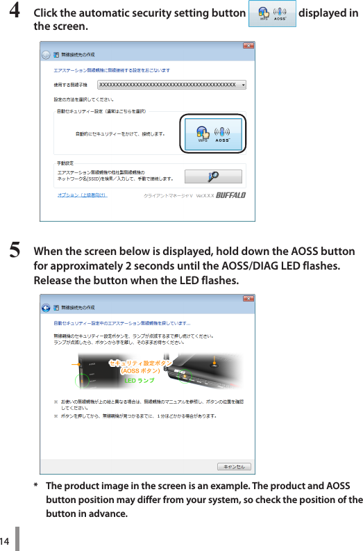
![132 When the screen below is displayed, click [Create connection destination].3 When the ”User Account Control” screen is displayed, click [Yes] or [Continue].](https://usermanual.wiki/Quanta-Computer/QD8.user-manual/User-Guide-1625939-Page-14.png)
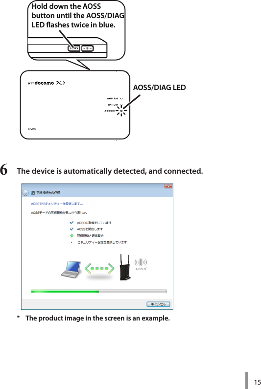
![167 Wait for the connection to complete.8 When ”Connection with AOSS completed” or ”Connection with WPS push-button type completed” is displayed, check the name of the connection destination, and click [Save and close].* The product image in the screen is an example. Note The connection destination name can be freely set.](https://usermanual.wiki/Quanta-Computer/QD8.user-manual/User-Guide-1625939-Page-17.png)
![179 When ”Wireless connection destination creation completed” is displayed, click [Close].10 If a screen ”Set Network Location” is displayed, click the location that matches the environment where the devices will be used. (In the example here, click ”Home Network”.)](https://usermanual.wiki/Quanta-Computer/QD8.user-manual/User-Guide-1625939-Page-18.png)
![1811 If the ”User Account Control” screen is displayed, click [Yes] or [Continue].12 If the screen below is displayed, click [Close].This completes connecting to this product. Note If connecting to this device fails, the AOSS/DIAG LED will continuously flash in blue for approximately 30 minutes, and a screen like the one below is displayed. In such case, click ”Start creating wireless connection from the beginning” and implement the procedures again from step 4 (PageP14).* Sample screen.](https://usermanual.wiki/Quanta-Computer/QD8.user-manual/User-Guide-1625939-Page-19.png)