Quanta Computer QD8 Portable Router User Manual BF 01C
Quanta Computer Inc Portable Router BF 01C
Contents
- 1. manual
- 2. user manua
- 3. user manual
user manual
BF-01D
User Manual
Introduction
Installing the BF-01D
Wireless Connection to the BF-01D
Internet Connection Settings
Use Overseas
Troubleshooting
1
2
3
4
5
6
Thank you for purchasing the BF-01D.
This manual describes product installation and its
default settings. It also provides troubleshooting
information. Please always read this manual before
using the product.
Appendix 7

1
1 Introduction
1
Main Features
This section describes the main product features.
• Supports NTT Docomo ”Xi”. (When receiving: Max. 37.5 Mbps; When sending: Max.
12.5 Mbps)
* The communication speeds are the maximum values in sending and receiving
standards. However, these do not indicate actual communication speeds. Data
transmission is provided over a best-effort network. For that reason, actual
communication speeds may vary according to the communication environ-
ment and the traffic load on the network.
* When outside of the Xi area, this can also be used in a FOMA high-speed area
(when receiving: Max. 14 Mbps; when sending: Max. 5.7 Mbps).
• The Internet connection automatically switches in public wireless LAN areas, such
as Mzone, from the Xi line or FOMA line to the public wireless LAN.
• The included cradle provides a wired port connection, and recharges the product.
• Connects up to 12 wireless LAN devices, such as personal computers and game
consoles.
• Connects to wireless LAN devices with one touch using AOSS or WPS.
Operating Environment
This section describes the product operating environment.
Supported Devices
iPad, iPod touch, game console (Nintendo 3DS™, Nintendo DS®, PSP® ”PlayStation
Portable”), and devices that support wireless LAN.

2
Supported OS (Personal Computers)
Windows 7 (32 bit/64 bit), Vista (32 bit/64 bit), XP (32 bit),
Mac OS X (10.4/10.5/10.6/10.7)
* Supports Windows 7 Starter/Home Premium/Professional/Ultimate.
* Supports Windows Vista Home Basic/Home Premium/Business/Ultimate.
* Windows XP must have Service Pack 3 or later installed.
Supported Browsers
Internet Explorer 7/8/9
Firefox 3.5.x/3.6.x/4/5
Nintendo DS Browser, Nintendo DSi Browser, Nintendo 3DS Internet Browser
PSP® Internet Browser
Safari 3.x/4.x/5.x (Mac OS/iPad/iPod touch)
* To change the product's settings, or to check the setting contents, use Internet
Explorer 7/8/9, or Firefox 3.5.x/3.6.x/4/5 (Windows 7/Vista/XP). Browsers provided in
game console or cell phones cannot implement all product settings.
3
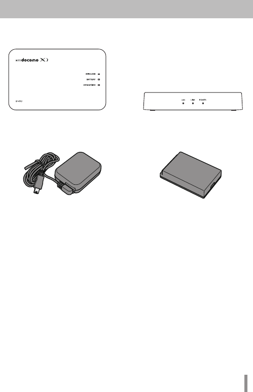
Mobile Wi-Fi Router (BF-01D) Unit
(Rear Cover BF02, Includes Warranty)
Desktop Cradle BF02 (Includes
Warranty)
AC Adapter BF01 (Includes Warranty) Battery Pack BF01
Main Unit Accessories
Before using this product, check that all of the accessories are included.
4
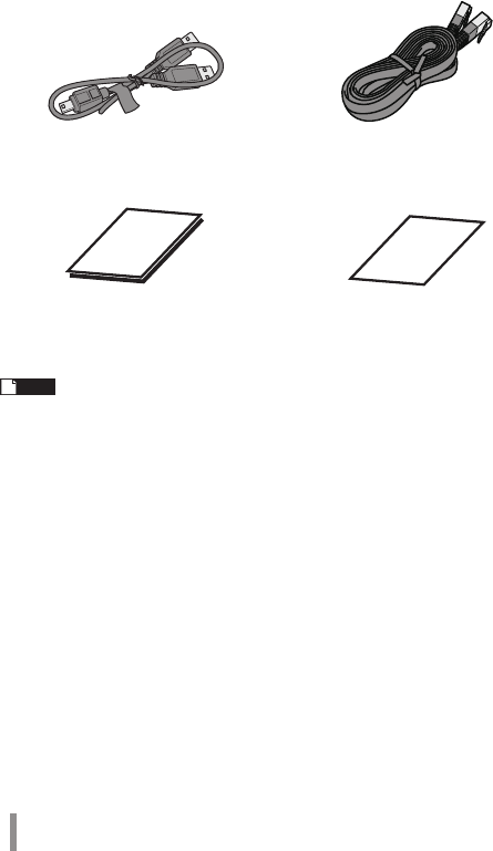
Note If separate, additional information is included, refer to that.
USB Cable BF01 LAN Cable (Free Sample)
User Manual (This Manual) Mobile Device Connection Guide
5
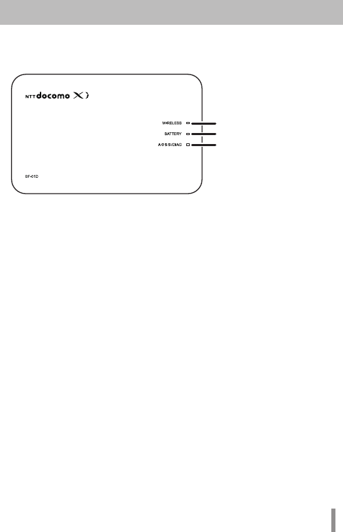
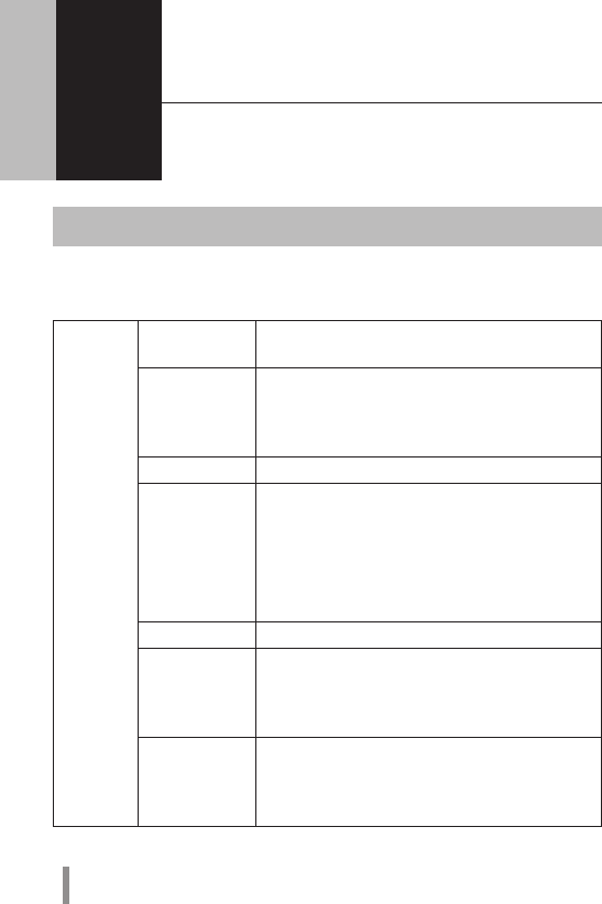
Part Names and Functions
Front Panel
1. WIRELESS LED
Glowing (blue) : When in Xi area
Glowing (purple) : During packet communication (with no sent or received
data)
Glowing (light blue) : When in FOMA area
Glowing (green) : When in wireless LAN area
Glowing (red) : When outside of Xi area, FOMA line and wireless LAN area, and
when not connected to wired Internet
Glowing (yellow) : When in power saving mode
Flashing (blue) : When communicating on Xi line
Flashing (light blue) : When communicating on FOMA line
Flashing (green) : When communicating on wireless LAN
Off : When connected to wired Internet
2. BATTERY LED
Glowing (blue) : Battery capacity is 50% or higher
Recharging is completed and the power is turned on
Glowing (green) : Battery capacity is 50 - 25%
Glowing (red) : Battery capacity is 25 - 10%
Flashing (red) : Battery capacity is 10% or lower
Flashing (purple) : Updating the firmware
Glowing (light blue) : Recharging
Glowing (purple) : Stop recharging because of the temperature error
Off : Recharging is completed and the power is turned off
* Battery capacity is a general indicator.
1
2
3

6
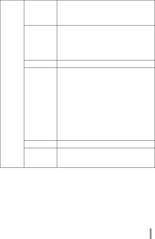
3. AOSS/DIAG LED
Glowing (yellow) : Security key exchange succeeds (AOSS/
WPS succeeds)/Wireless LAN security setting
completed
Flashing Two Times (blue) : This product can exchange security keys.
(LAN Side: AOSS/WPS Idling)
(Internet Side: AOSS Idling) *1
Continuous Flashing (blue) : Failed to exchange security keys (AOSS/WPS failed)
Flashing (red) : The number of flashes indicates the status of the
product.
Off : Wireless LAN security is not set.
Flashing (red)
status Content Status
Continuous
Flashing *2
• Booting up system
• Saving settings
• Initializing
• Accessing internal storage region
Flashing Three
Times *3
Wired LAN Error Wired LAN controller is
malfunctioning.
Flashing Four
Times *3
Wireless LAN error Wireless LAN controller is
malfunctioning.
Flashing Five
Times
IP Address Setting Error Communication is not possible
because the network addresses are
the same on the Internet side and
the LAN side. Change the product's
LAN-side IP address setting.
Flashing Six
Times
Temperature Error The internal product temperature
is high. Turn the power to the
product off and allow it to cool for
a while before using it.
7
*1 Devices idling with AOSS switch to flashing two times (yellow) when
detected by the Internet side of the product.
*2 Do not turn off the power when the device is continuously flashing. Doing
so can damage it.
*3 When the AC adapter is disconnected from the device, turn off the power
to it, and remove the battery pack. Return the battery pack to its original
position after waiting for a while.
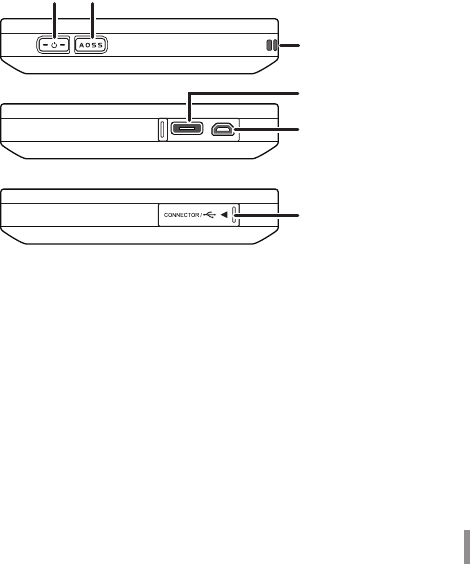
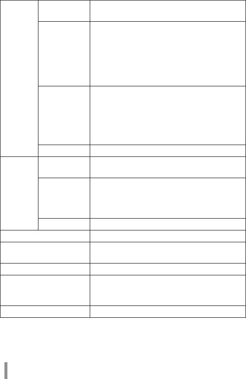
Side
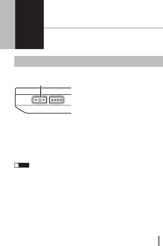
4. Power Button
When the power is off, hold down the power button for approximately three
seconds to turn the power on. When operating this device, hold down the
power button for approximately three seconds to turn the power off.
5. AOSS Button
When the power is on, hold down the button (for approximately three
seconds) until the AOSS/DIAG LED flashes in blue to enter a status (AOSS
operating status) where security keys can be exchanged.
6. Strap Hole
Attaches commercially available straps.
7. Cradle Connector
Connects the included cradle.
4 5
connector cover
6
7
8
8
8. mini USB Connector
Connects the included AC adapter or a USB cable.
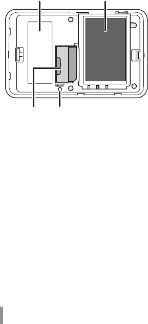
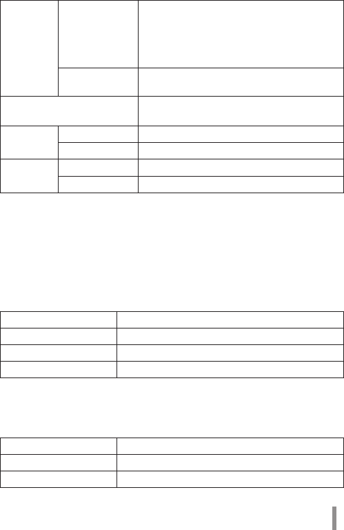
Back Side
9. Default Value Label
Lists this unit’s SSID (default value) and encryption key (default value) and the
like.
10. Battery Box
Holds the included battery pack.
11. UIM Card Slot
For inserting a Docomo UIM card.
* This device does not support the use of FOMA cards. If you have a FOMA
card, please replace it from your Docomo vendor.
12. RESET Switch
When the power to this device is on, hold down the RESET button (for
approximately three seconds) until the AOSS/DIAG LED flashes in red to
initialize the settings.
9 10
11 12
9
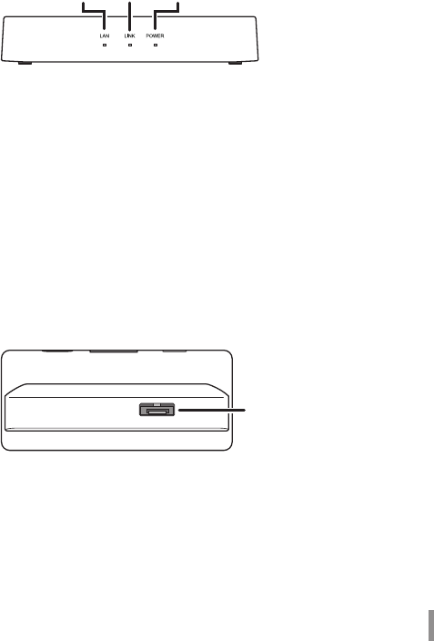
Cradle Front Side
Cradle Top
13. LAN LED
Glowing (green) : When the wired port is set as the LAN port
Off : When the wired port is set as the INTERNET port
14. LINK LED
Glowing (green) : When the wired port is linked
Flashing (green) : When the wired port is communicating
15. POWER LED
Glowing (green) : When the included AC adapter is connected
16. Cradle Connector
Connects the main unit's cradle connector.
13 14 15
16
10
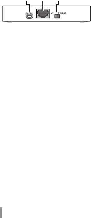
Cradle Back Side
17. POWER Connector
Connects the included AC adapter.
18. Wired Port
Switch to operate this as the LAN port or the INTERNET port by using the on-
off switch.
19. On-off Switch
Switch to use the wired port either as the LAN port or the INTERNET port.
17 18 19
11
2 Installing the BF-01D
2
Power ON/OFF
Turn the power ON/OFF using the power button.
When the power is off, hold down the power button for approximately three seconds
to turn the power on.
When operating this device, hold down the power button for approximately three
seconds to turn the power off.
Note
In the default setting, if no wireless device is connected to the product
for approximately one minute, it will automatically switch to standby
mode. Operations such as connecting to the Internet do not work while
the unit is in standby mode. But the system will recover to its normal
operating status either by pressing the power button or by connecting
a wireless device to the product. However, the system will not shift to
standby mode while power is being supplied or when it is connected to a
wired port.
Power Button

12
3
Wireless Connection to the BF-01D
3
Wireless Connection to a Personal Computer
This section describes the procedures for connecting this product wirelessly to a
personal computer running Windows, using AOSS/WPS (push-button type) as an
example. Setting methods vary according to the version of Windows that is running.
For Windows 7/Vista
Follow the procedure below to connect to this device using AOSS/WPS (push-button
type) on a personal computer running Windows 7 or Vista.
Note In setting AOSS/WPS (push-button type), the personal computer and this
device establish a 1-to-1 relationship. For that reason, you cannot
connect another device with AOSS/WPS (push-button type) while it is
being set. To connect multiple devices to one BF-01D unit, connect
another device after completing the AOSS/WPS (push-button type)
connection.
1 Select [Start] - [(All) Programs] - [BUFFALO] - [AirStation Utility] -
[Client Manager V].
13
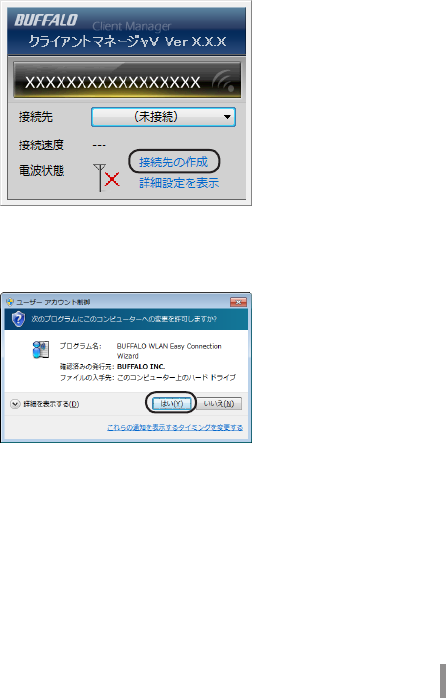
2 When the screen below is displayed, click [Create connection
destination].
3 When the ”User Account Control” screen is displayed, click [Yes] or
[Continue].
14
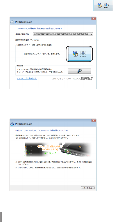
4 Click the automatic security setting button displayed in
the screen.
5 When the screen below is displayed, hold down the AOSS button
for approximately 2 seconds until the AOSS/DIAG LED flashes.
Release the button when the LED flashes.
* The product image in the screen is an example. The product and AOSS
button position may differ from your system, so check the position of the
button in advance.
15
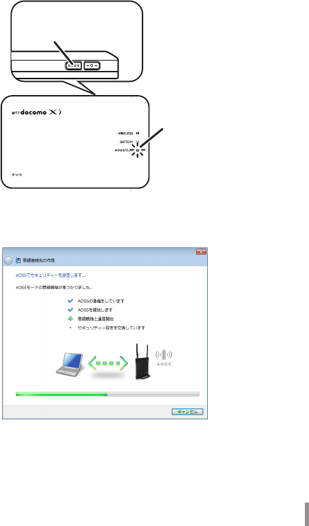
6 The device is automatically detected, and connected.
* The product image in the screen is an example.
Hold down the AOSS
button until the AOSS/DIAG
LED ashes twice in blue.
AOSS/DIAG LED
16
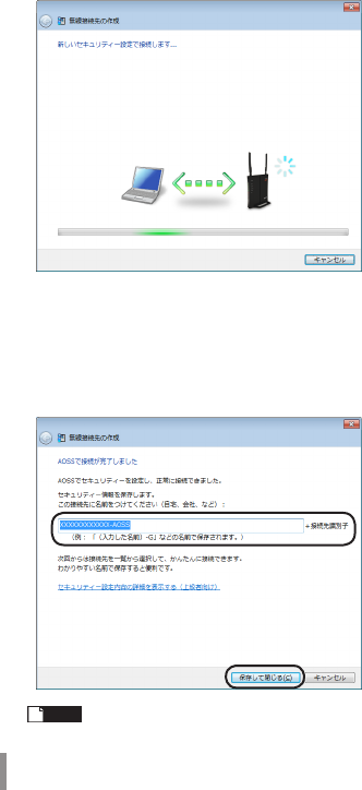
7 Wait for the connection to complete.
8 When ”Connection with AOSS completed” or ”Connection with WPS
push-button type completed” is displayed, check the name of the
connection destination, and click [Save and close].
* The product image in the screen is an example.
Note The connection destination name can be freely set.
17
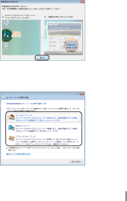
9 When ”Wireless connection destination creation completed” is
displayed, click [Close].
10
If a screen ”Set Network Location” is displayed, click the location
that matches the environment where the devices will be used.
(In the example here, click ”Home Network”.)
18
11
If the ”User Account Control” screen is displayed, click [Yes] or
[Continue].
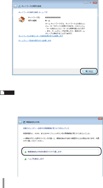
12
If the screen below is displayed, click [Close].
This completes connecting to this product.
Note
If connecting to this device fails, the AOSS/DIAG LED will continuously
flash in blue for approximately 30 minutes, and a screen like the one
below is displayed. In such case, click ”Start creating wireless connection
from the beginning” and implement the procedures again from step 4
(PageP14).
* Sample screen.
19
4 Troubleshooting
4
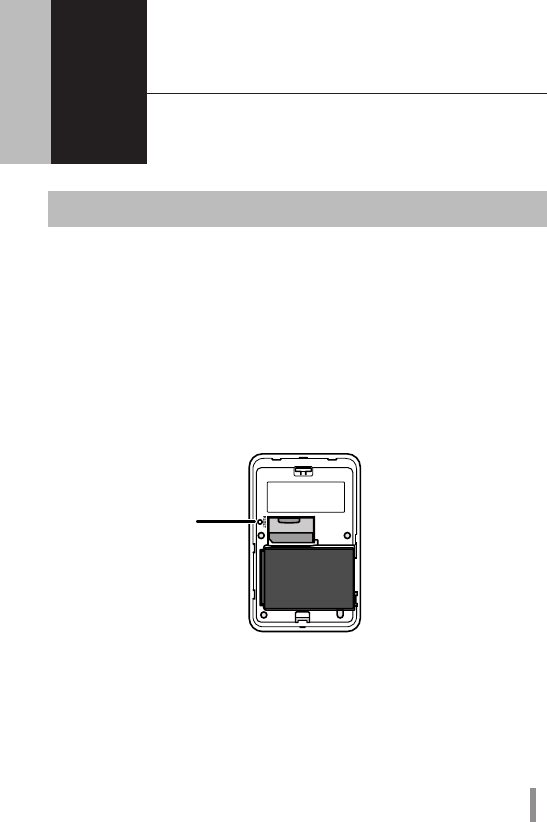
Initializing the Settings
Use the following procedures to initialize the settings (Reset).
1 Check that the power to the device is on.
2 Remove the back side cover.
3 Hold down the RESET button (for approximately three seconds)
until the AOSS/DIAG LED flashes in red.
4 After about one minute, check that the AOSS/DIAG LED is lit in yellow.
This completes initialization of this product.
RESET Button
20
5 Appendix
5
Product Specifications
Main Unit/Cradle
Wireless
Interface
(LAN Side)
Compliance
Standards
IEEE802.11b / IEEE802.11g / IEEE802.11n
ARIB STD-T66 (IEEE802.11b/g)
Maximum Data
Transfer Speed
(Theoretical
Value)
IEEE802.11b 11Mbps
IEEE802.11g 54Mbps
IEEE802.11n 150Mbps
Mode Access Point (AP) Mode
Frequency
Range
2412 - 2472 MHz 1 - 13 channels
* When being used overseas (international roaming), the
range is restricted to 2412 - 2462MHz and 1 - 11 channels.
* Basically, signals do not cross-talk (or interfere) with those
of other devices, such as cell phones, cordless telephones,
televisions, radios and the like, but if these devices are
wireless with a 2.4 GHz band, there is the possibility that
cross-talk can occur.
No. of Ports 1 Port
No. of Devices
That Can Be
Connected
Simultaneously
12 Devices
Security WPA2-PSK (TKIP/AES), WPA-PSK (TKIP/AES), WPA/
WPA2 mixed PSK (AES), WEP (64bit/128bit) privacy
separator, ANY connection rejection, MAC access
restrictions (up to 16 devices)
21
Wireless
Interface
(Internet
Side)
Compliance
Standards
IEEE802.11a / IEEE802.11b / IEEE802.11g /
IEEE802.11n
ARIB STD-T71 (IEEE802.11a)
ARIB STD-T66 (IEEE802.11b/g)
Maximum Data
Transfer Speed
(Theoretical
Value)
IEEE802.11a 54Mbps
IEEE802.11b 11Mbps
IEEE802.11g 54Mbps
IEEE802.11n 150Mbps
* IEEE802.11a cannot be used when the device is set for
international roaming.
Mode Station (STA) Mode
Frequency
Range
5 GHz Band W52 36/40/44/48 channels
(5180 - 5240MHz)
W53 52/56/60/64 channels
(5260 - 5320MHz)
2.4 GHz Band 1 - 13 channels
(2412 - 2472MHz)
* When the device is being used overseas (international
roaming), the range is restricted to 2412 - 2462MHz and 1 -
11 channels. Also, cannot be used in 5GHz band.
* Basically, signals do not cross-talk (or interfere) with those
of other devices, such as cell phones, cordless telephones,
televisions, radios and the like, but if these devices are
wireless with a 2.4 GHz band, there is the possibility that
cross-talk can occur.
No. of Ports 1 Port
Security WPA2-EAP (TKIP/AES), WPA-EAP (TKIP/AES), WPA2-
PSK (TKIP/AES), WPA-PSK (TKIP/AES), 802.1X/EAP
(WEP), WEP (64bit/128bit)
22
Mobile
Interface
Compliance
Standards
LTE (Cat.3) / W-CDMA (R99) / HSDPA (Cat.10) / HSUPA
(Cat.6)
Maximum Data
Transfer Speed
(Theoretical
Value)
LTE (Indoor) UP: 25 Mbps Down: 75 Mbps
LTE (Outdoors) UP: 12.5 Mbps Down: 37.5 Mbps
W-CDMA UP: 384 kbps Down: 384 kbps
HSDPA 14.4 Mbps
HSUPA 5.7 Mbps
* LTE cannot be used when the device is set for international
roaming.
Frequency
Range
Band I 2100 MHz UP : 1920 - 1980 MHz
Down : 2110 - 2170 MHz
Band V 850 MHz UP : 824 - 849 MHz
Down : 869 - 894MHz
Band VI 800 MHz UP : 830 - 840 MHz
Down : 875 - 885MHz
No. of Ports 1 Port
Cradle Compliance
Standards
IEEE802.3u (100BASE-TX)
IEEE802.3 (10BASE-T)
Maximum Data
Transfer Speed
(Theoretical
Value)
10/100 Mbps (Automatic Recognition)
No. of Ports 1 Port (Supports AUTO-MDIX)
Supported UIM Card Docomo UIM Card
Other Unit External
Interfaces
mini USB (Supports USB 1.1/2.0) x 1
Built-in Flash Region Approximately 16 GB
Power AC100V ±10% 50/60Hz (When using AC adapter)
BF-01D Dedicated Battery (When using battery
pack)
Consumption Current 620 mA (Max)
23
Battery Pack
Part Name Battery Pack BF01
Battery Type Lithium-ion Battery
Nominal Voltage DC 3.7 V
Nominal Capacity 1880 mAh
AC Adapter
Part Name AC Adapter BF01
Input AC100 - 240V 50/60Hz 11.2 - 14.8VA
Output DC 5 V 1 A
Continuous
Communi-
cation Time
When
Communicating
When in LTE Communication
Approximately 4 Hours
When in 3G communication
Approximately 5.5 Hours
* Operating times vary according to the environment of use.
When in Standby Approximately 30 Hours
* Operating times vary according to the environment of use.
Operating Environment Temperature: 0 - 35°C
Humidity: 10 - 85% (no condensation)
External
Dimensions
Main Unit Approximately 108 (W) x 68 (H) x 20 (D) mm
Cradle
Approximately 115 (W) x 21 (H) x 50 (D) mm
Weight Main Unit Approximately 143 g (When battery pack is installed)
Cradle
Approximately 43g
Software licensed by GNU General Public License (GPL) or GNU Lesser General Public
License (LGPL) is included with this product. For details on this software, see NTT's
homepage (http://www.nttdocomo.co.jp/).

24
Export Administration Regulations
This product and its accessories may be subject to Japan's Export Administration
Regulations (Foreign Exchange and Foreign Trade Control Law). It also may be
subject to American Re-exporting Regulations (Export Administration Regulations).
To export or re-export this product and its accessories, use the necessary procedures
at your own responsibility and cost. For details on procedures, please contact the
Ministry of Economy, Trade and Industry or the U.S. Department of Commerce.
Regulatory Information
Federal Communications
Commission (FCC) Statement
15.21
You are cautioned that changes or modications not expressly
approved by the part responsible for compliance could void the user’s
authority to operate the equipment.
15.105(b)
This equipment has been tested and found to comply with the limits
for a Class B digital device, pursuant to part 15 of the FCC rules. These
limits are designed to provide reasonable protection against harmful
interference in a residential installation. This equipment generates,
uses and can radiate radio frequency energy and, if not installed and
used in accordance with the instructions, may cause harmful
interference to radio communications. However, there is no guarantee
that interference will not occur in a particular installation. If this
equipment does cause harmful interference to radio or television
reception, which can be determined by turning the equipment o and
on, the user is encouraged to try to correct the interference by one or
more of the following measures:

25
• Reorient or relocate the receiving antenna.
• Increase the separation between the equipment and receiver.
• Connect the equipment into an outlet on a circuit dierent from
that to which the receiver is connected.
• Consult the dealer or an experienced radio/TV technician for help.
This device complies with Part 15 of the FCC Rules.
Operation is subject to the following two conditions:
1)thisdevicemaynotcauseharmfulinterferenceand
2) this device must accept any interference received, including
interference that may cause undesired operation of the device.
FCC RF Radiation Exposure Statement:
Forbodywornoperation,thisdevicehasbeentestedandmeets
FCCRFexposureguidelineswhenusedwithanaccessorythat
containsnometalandthatpositionsthedeviceaminimumof1.0
cmfromthebody.Useofotheraccessoriesmaynotensure
compliancewithFCCRFexposureguidelines.
SAR information: 0.573W/Kg(1g)

26
CE Marking
This device has been tested to and conforms to the regulatory
requirements of the European Union and has attained CE Marking. The
CE Mark is a conformity marking consisting of the letters ”CE”. The CE
Mark applies to products regulated by certain European health, safety
and environmental protection legislation. The CE Mark is obligatory for
products it applies to: the manufacturer axes the marking in order to
be allowed to sell his product in the European market.
This product conforms to the essential requirements of the R&TTE
directive 1999/5/EC in order to attain CE Marking. A notified body has
determined that this device has properly demonstrated that the
requirements of the directive have been met and has issued a
favorable certificate of expert opinion. As such the device will bear the
notified body number 0560 after the CE mark
The CE Marking is not a quality mark. Foremost, it refers to the safety
rather than to the quality of a product. Secondly, CE Marking is
mandatory for the product it applies to, whereas most quality
markings are voluntary.
Marking: The product shall bear the CE mark, the notified body
number(s) as depicted to the right. CE 0560.
SAR information: 0.637W/Kg(10g)