Quanta Computer QF3A Media AIO PC User Manual
Quanta Computer Inc Media AIO PC
User Manual

BU12 Quanta Computer Inc
QT-195W-aa2 Media AIO PC
User Manual
Date: Aug. 2017

1
Important Safety Instruction
1. DO NOT place objects on top of the device, as objects may scratch the screen.
2. DO NOT place the device on an uneven or unstable surface.
3. DO NOT insert any foreign objects into the device.
4. DO NOT expose the device to strong magnetic or electrical field.
5. Please check with your Local Authority or retailer for proper disposal of electronic
products.
6. POWER INPUT RATING: Refer to the rating label on the device and be sure that the
power adapter complies with the rating. Only use the power supply specified by the
manufacturer.
7. WARNING: To avoid risk of electric shock, this device must only be connected to a
supply mains with protective earth”
8. DO NOT use a pen or any sharp object to tap the screen.
9. Clean the device with a soft, dampened cloth. Use 75% alcohol by-weekly for
disinfection.
10. Always power off the device to install or remove external devices that do not support
hot-plug.
11. Disconnect the device from an electrical outlet and power off before cleaning the device.
12. DO NOT disassemble the device. Only a certified service technician should perform
repair.
13. PLUGGABLE EQUIPMENT: the socket-outlet shall be installed near the equipment and
shall be easily accessible.
Please read the following before continuing setup:
● Make sure to use the power transformer(AC adapter) which is supplied by the
manufacturer. Use of unauthorized parts may cause the warranty to being void.
● Do not store the unit in the environment of the temperatures exceeding 60° C.
● Operating temperature of the device is within the range of 0° C to 35° C.

2
Important Safety Instruction .................................................................................................. 1
Introduction .............................................................................................................................. 3
Intended use .............................................................................................................................. 4
Summary of Application specifications .................................................................................. 5
Unpacking your smart terminal ............................................................................................. 7
Knowing QOCA Terminal ....................................................................................................... 8
Front view ............................................................................................................................. 8
Back View .............................................................................................................................. 9
Bottom View ........................................................................................................................ 10
Specification ........................................................................................................................ 11
Setup QOCA ........................................................................................................................... 13
Attaching to Arm ................................................................................................................ 13
Connect to Power ............................................................................................................... 14
Turn On and Off the Device .............................................................................................. 15
Power On .......................................................................................................................... 16
Power Off ......................................................................................................................... 16
Connect to the other USB devices .................................................................................... 17
Elucidations of the Icons Displayed...................................................................................... 18
Troubleshooting ...................................................................................................................... 20
QOCA Contacts ...................................................................................................................... 21
Appendix ................................................................................................................................. 22

3
Introduction
QOCA smart terminal is an all-in-one PC and tablet with a 19.5” touch display. It is being
used as a bedside terminal in the hospital, to provide medical information & preventive health
care for users in hospital. Hospital should install the terminal with an arm securely mounted
around the bed, to provide easy access for users in hospital.

4
Intended use
According to the definition of production specification of QOCA, this media AIO PC will be
endued with the following intended uses:
This medical PC will be widely used in point-to-point nursing care throughout the hospital
system environment from the ward to the station. By way of internet infotainment
information, this terminal can provide the patient with great assistance of essential medical
information, which is also able to improve the workflows of nurse & doctor and streamline
the collection & storages of the patient records.
This medical All-in-One PC with the abundant technological features is designed for great
interactive connectivity interfaces with other accessory compatible devices & offers two
independent USB 2.0 ports, one USB 3.0 port & one Ethernet port to connect arbitrarily.
Besides, QOCA also provides amazingly full & complete compatibility characteristics with
Google Android system (Operation System base) & Quanta QOCA medical management
system (Application Program base).
Nevertheless, this QOCA also supports external DC 19.1V with AC/DC medical grade power
adapter. This important medical grade AC adapter can make sure that QOCA is used safely &
effectively to users in all the corners of the hospital.

5
Summary of Application specifications
Application specifications are mainly derived from design inputs in the product development
phase. In this certain stage, intended use, patient population, body contact part, intended use
profile, use scenario(environment), use frequency, and interactive mobility are definitely
identified & regulated very much as application specifications
Intended Use:
This medical PC will be widely used in point-to-point nursing care throughout the hospital
system environment from the ward to the station. This terminal can provide the patient with
great assistance of essential medical information inquiry, which is also able to improve the
workflows of nurse & doctor and streamline the collections & storages of the chart records.
User Population:
Limit in general users in hospital with consciousness.
Significant Physical Part:
The most contact part of the physical body applied to or interacted with is skin in fingers.
Intended User Profile:
Based on elucidations of the intended use, this device of QOCA can heighten working
efficiency in hospital. This device can be used & operated by the following personnel:
● Medical professionals
● Laymen without the medical backgrounds
Operating Principle:
This QOCA is mainly an All-in-One personal computer (PC), which is endued with some
essential interfaces of USB 2.0, USB3.0, OTG, and Ethernet. It can functionalize & work
well via external electric supply of DC 19.1V of the medical grade power adapter. Besides,
based on the basic function supports, it also provides users with sufficient systematic
compatibility with Android & comprehensive program applications with QOCA management
system.
Performance Characteristics:
Performances of this specific & medical media All-in-one PC is more powerful & superior
than the general ones on the market. It has a very fundamental ability of operation (browse

6
information & internet access) & process (mathematics calculation) as an identity of PC.

7
Unpacking your smart terminal
Your new smart terminal comes packed in a protective box. Carefully unpack the box and
remove the contents. If any of the following items is missing or damaged, contact your dealer
immediately:
Quanta QOCA smart terminal device (Model name: QT-195W-aa2 )
User guide (this document)
This icon stands for user guide (user manual).
Power adapter kit
Back cover
8
Knowing QOCA Terminal
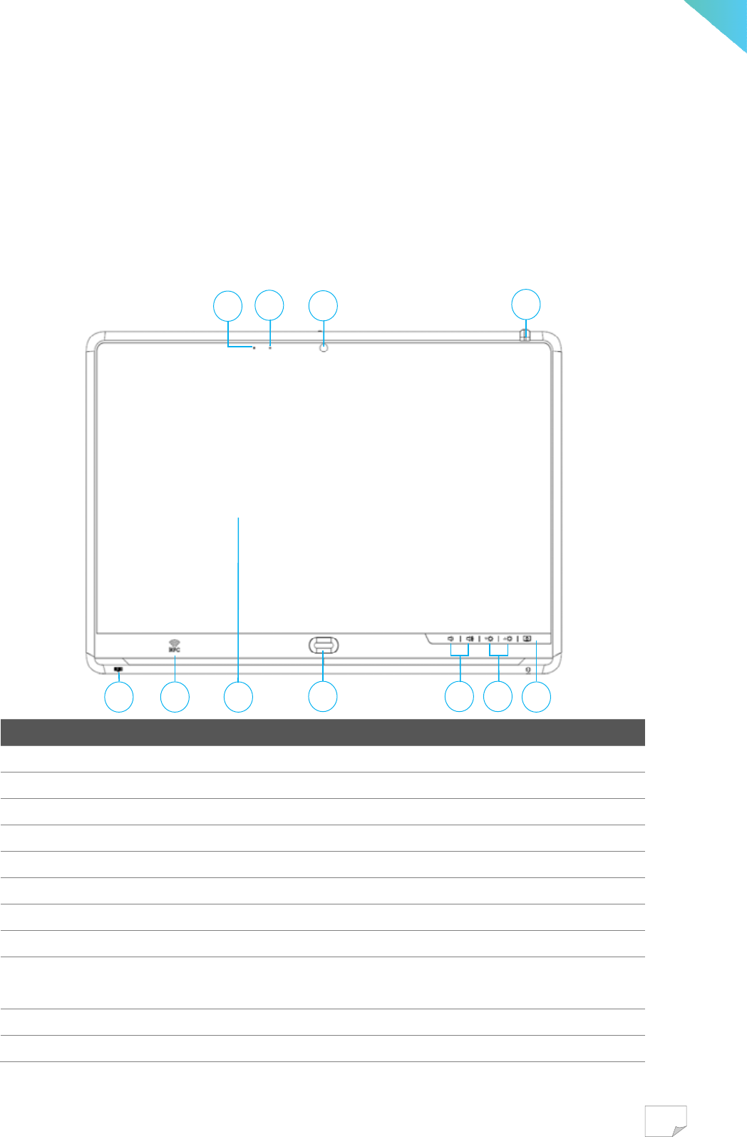
Front view
No. Item Description
1 Screen button Button to turn on/off the display.
2 Brightness control Buttons to increase/decrease screen brightness.
3 Volume control Buttons to increase/decrease audio volume.
4 NFC reader RFID (NFC) reader.
5 User-defined button Customizable button.
6 Touchscreen 19.5” display with multi-touch support.
7 Barcode scanner Support reading of 1D/2D barcode.
8 Microphone Receives audio for audio and video calls.
9 Power indicator Indicate power status. Off: power not connected; Blue:
power status is OK.
10 Front-facing camera 1080p camera.
11 LED status indicator Software-defined multi-color LED status indicator.
11
10
9
8
1
235
47 6
9
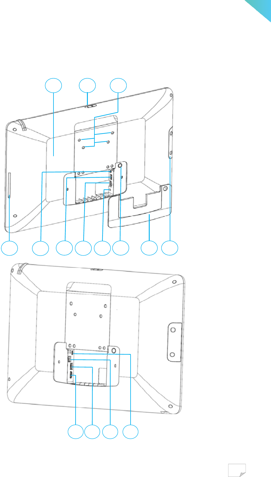
Back View
12
19 1314
1516
17
18
21 2220
232425
26
10
No. Item Description
12 Handset attachment Area to install optional handset.
13 Port cover Open this cover to find the power, network, and USB ports.
14 Power button Button to power on/off the device.
15 Power jack Connects to a DC power adaptor.
16 Ethernet port Connects to a network.
17 USB 3.0 port Connects USB devices to your device, such as an optional
handset or USB keyboard or USB mouse.
18 Audio jack Connects to a earphone.
19 Smart Card reader Slot for smartcards.
20 Wireless receiver Built-in Wi-Fi & Bluetooth for wireless communication.
21 Camera shutter Shutter to open/close front-facing camera.
22 Screw holes Holes to attach arm plate.
23 Micro USB port Connects Micro USB devices to your device
24 Call button port Connect to patient bed call button
25 USB 2.0 port Connects USB devices to your device
26 HDMI port Connects HDMI devices to your device
WARNING
End user can utilize USB connectors to extend other devices. Please kindly
confine in types of USB keyboard, USB mouse, or an optional handset.
Please do not use these USB ports to make charge.
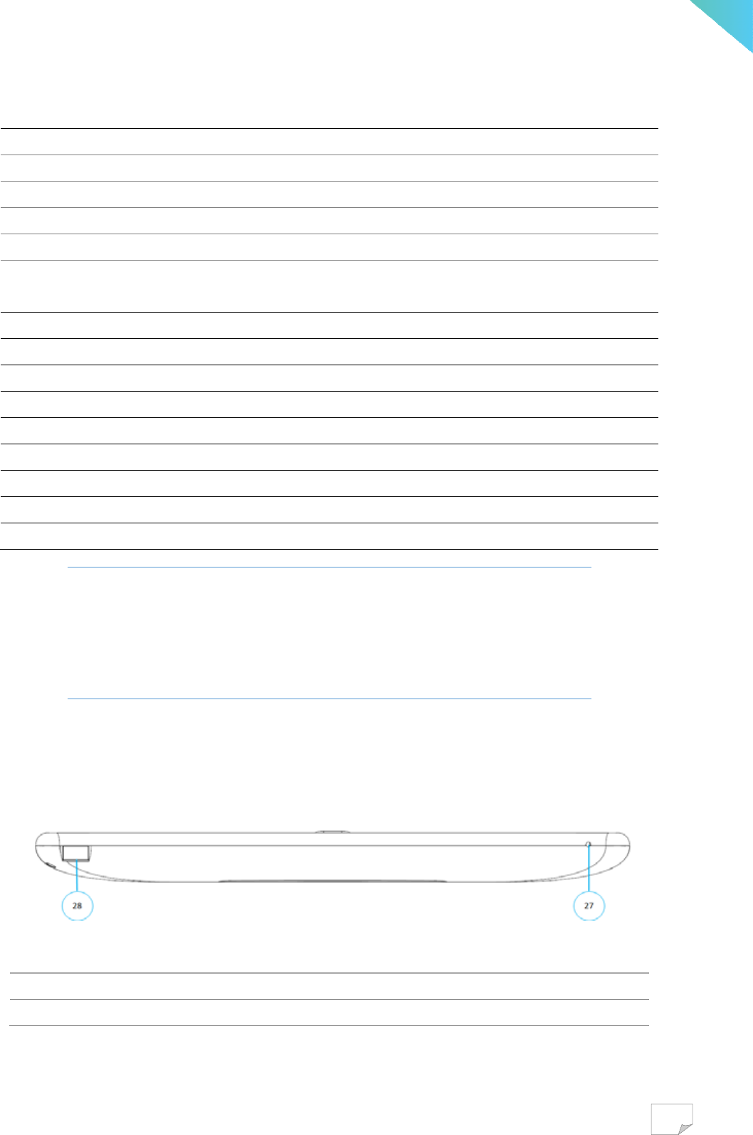
Bottom View
No. Item Description
27 MIC/audio jack Connects to a headphone.
28 Barcode scanner Support reading of 1D/2D barcode.

11
Specification
Equipment classification information
Medical class Class I device
System
CPU ROCKCHIP RK3399, Dual core A72+Quan A53 2.0 GHz, BGA
Memory 2GB RAM
Storage 32GB
Operating System Google Android™ 7.1 Nougat as default
Input & output
Display 19.5-inch LED-backlit HD (1600 x 900) display (250 cd/m
2
)
Camera 5M (Support 1080p)
Touch screen Projected Capacitive, multi-touch, antimicrobial coating glass
RFID Reader (NFC) ISO 14443 A/B, ISO 18092, MIFARE, FeliCa
Barcode scanner 1D/2D barcode reader
Smart Card reader Integrated
Wi-Fi 802.11 b/g/n
Bluetooth Bluetooth 2.1 + EDR / BT4.0 HS
Ethernet 10/100M/1000M
USB 2.0 Type A x 1, 3.0 Type A x 1
Speaker 2.0W@ 4Ω x 2 speaker with 4.0W@ 4Ω sub-woofer
MIC/audio combo jack 3.5mm, Universal audio jack
Others
Power (AC adapter) AC 100-250V~, 1.5A, 50-60Hz
Delta MDS-060AAS19 B (for IEC 60601-1)
LED status indicator Blue
Cleaning 75% Alcohol solution (Cleansing Alcohol 75%)
Weight 3.7 kg
Dimensions 498mm x 331.6mm x 41.6mm
Mount Dependent on customer VESA 75mm x 75mm, 100mm x100mm

12
Operation environment
Temperature 0
o
C ~ 35
o
C
Humidity 35% ~ 75%
Atmospheric pressure 700 to 1060 hPA
Altitude 3000 meters
Storage environment
Temperature -20
o
C ~ 60
o
C(-4
o
F ~ 140
o
F)
Humidity 10% ~ 90%
Transportation environment
Temperature -20
o
C ~ 60
o
C(-4
o
F ~ 140
o
F)
Humidity 10% ~ 90%
Measurement environment
Temperature 0
o
C ~ 35
o
C
Humidity 35% ~ 75%
13
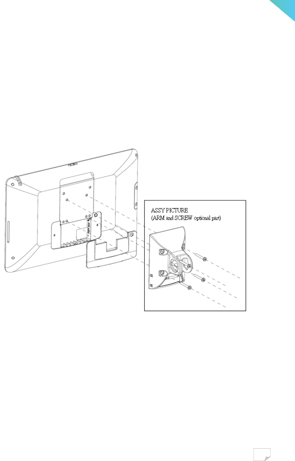
Setup QOCA
Attaching to Arm
Attach arm plate to the device using the 4 screw holes in a fashion indicated below.
Remember to install the back cover before attaching to arm.
14
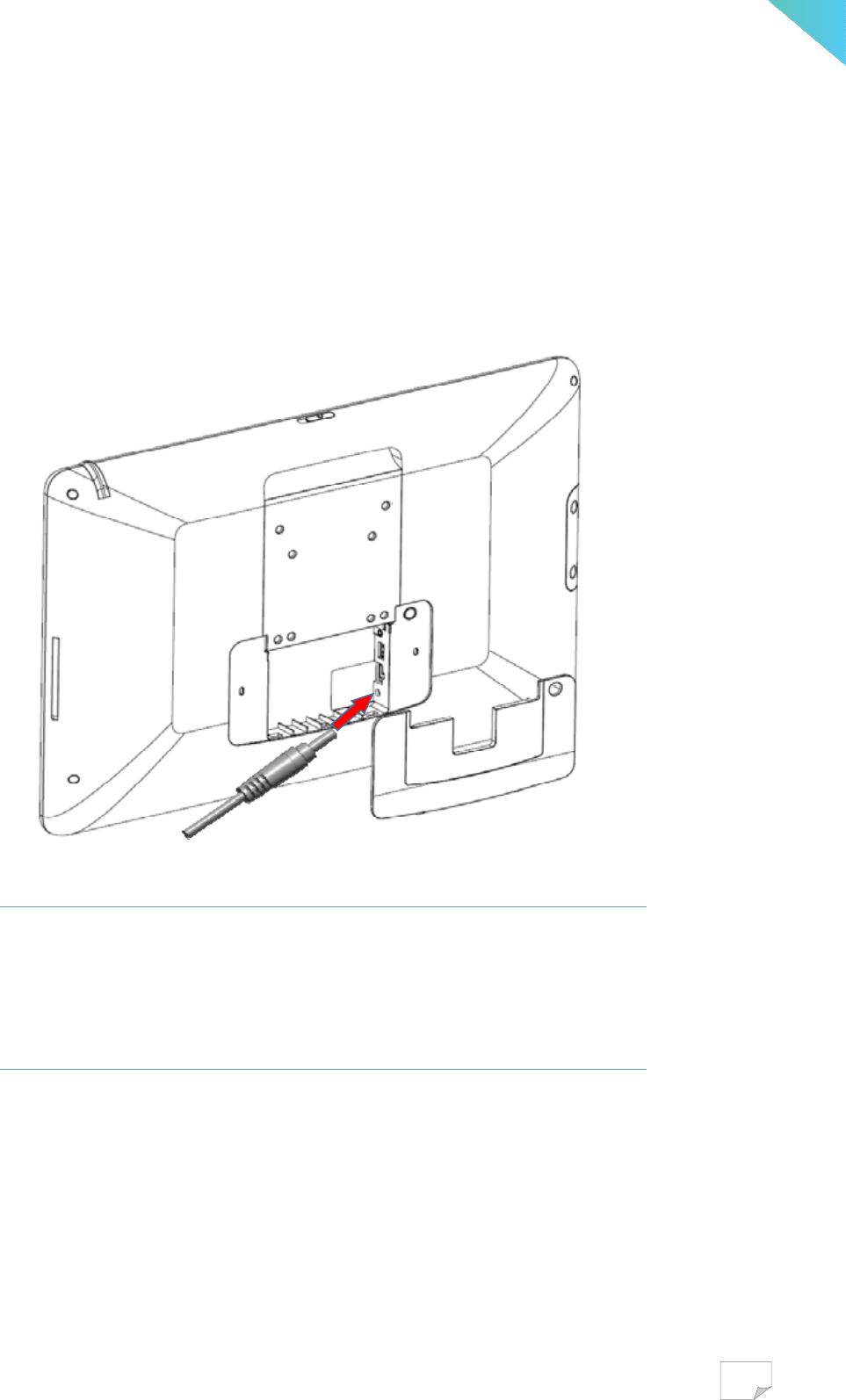
Connect to Power
1. Open the compartment cover on the back
2. Connect the included power adapter to the power jack
3. Connect the other end of power cord to suitable power outlet
WARNING
End user only use the power adapter provided by the manufacturer. Use of
unauthorized accessories may cause damage to the device and void your
warranty
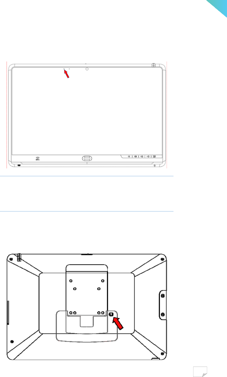
15
After power is properly connected, follow the below picture to check the blue LED and make
sure it is ON.
WARNING
In order to avoid risk of electric shock, this device must only be connected
to the supply mains with protective earth
Turn On and Off the Device
Power button is located on the back of the device

16
Power On
1. Press and hold the power button for 3 seconds.
2. Device logos and boot message will show up during the boot process
3. Android lock screen will appear, touch and slide the unlock icon to unlock
4. Android home screen is displayed, the device is ready to use
Power Off
There are two ways to power off the device. Please do turn off by the graceful way, which
allow Android to cleanly shut down the device. Only force shutdown the device when it is not
responsive.
Gracefully Power off
1. Press and hold the power button for 3 seconds until the shutdown dialog appear on screen.
2. Tap power off to shut down the device
Force Power off
1. Press and hold the power button for at least 10 seconds.
2. Screen display will shut off after 10 seconds. Now the device is powered off.
WARNING
Please do not to unplug the DC power cord or disconnect mains electricity
until the device is powered off. Unexpected power outage might cause data
loss or unrecoverable error.
Disconnect the device
1. Based on the schematics of this instrument, only the plug or the appliance inlet can
disconnect it immediately from electricity.
2. When the unexpected emergency condition happens, user can use either the plug or the
appliance inlet to disconnect the instrument from the electricity right away.
17
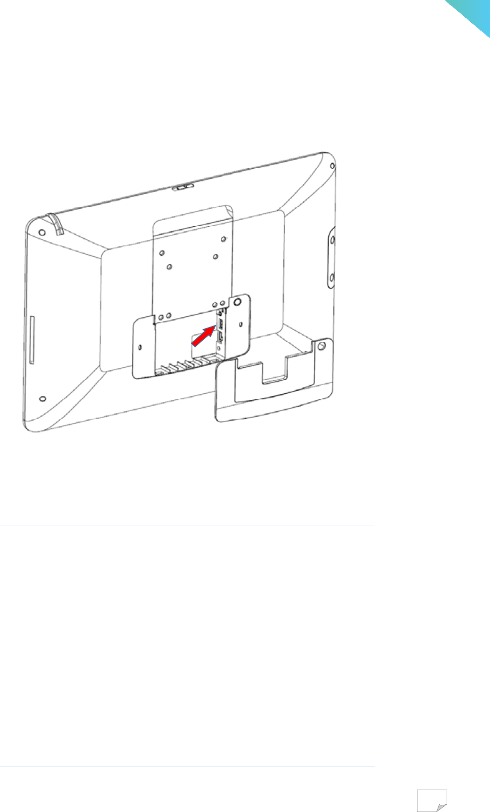
Connect to the other USB devices
1. Connects USB devices to your device, such as an optional handset.
2. Connect HID (Human Intelligent Device) to your device or such as a USB keyboard or
USB mouse.
WARNING
Accessory equipment connected to the analog and digital interfaces must be
in compliance with the respective nationally harmonized IEC standards (i.e.
IEC 60601-1 for medical equipment). Furthermore, all the mechanical &
electrical configurations shall be complied with the system standard
requirement in IEC 60601-1. Anyone who would like to connect additional
equipment parts to the signal input part or signal output part which is
configuring a medical system, and is therefore, in charge that the system
must be complied with the regulation requirements of the system standard
IEC 60601-1. The accessary unit is for exclusive interconnection with IEC
60601-1 certified equipment in the patient environment and IEC 60950
certified equipment outside of the patient environment.
18
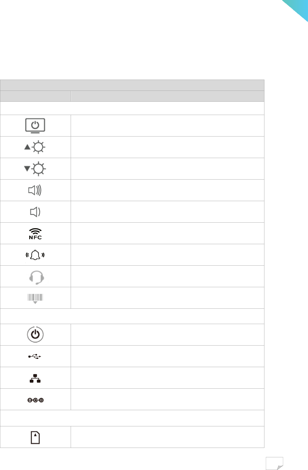
Elucidations of the Icons Displayed
Printing icons on the front bezel & the back cover
Symbol of icon Elucidation
Allocation in the front bezel
- Sleep(Suspend) touch button
- Brightness up touch button
- Brightness down touch button
- Volume up touch button
- Volume down touch button
- NFC sensing reader
- User-defined button(Customized button)
- Phone/MIC jack
- Barcode sensing reader
Allocation in the back cover
- Stand-by button [Sleep(Suspend) button (press 1 second)]
- USB port(Type A x 2)
- Ethernet jack
- DC-IN jack
Allocation in the right side of the back cover
- Slot of the smart card reader
19
The remaining icons on the rating label(the machine)
Symbol of icon Elucidation
Allocation in the rating labels of the machine and AC adapter
- BSMI(Taiwan) Safety & EMC Certification Logo
- R43039 means Quanta
- CE (European Union) EMC & RF Certification Logo
- 0120 means Notify body in the locale of EU
- User guide(user manual)
- FCC(USA) EMC & RF Certification Logo
- UL(USA) & cUL(Canada) Safety Certification Logo
- UL file number(E142692 means Quanta)
- NCC(Taiwan) RF Certification Logo
- CCAE16LP0720T1 – NCC RF certificate No.
- Green Product Recycle Mark
- IEC 60417-5032 Alternating current(AC) Mark
- IEC 60417-5031 Direct current(DC) Mark
-
20
Troubleshooting
Problem Solutions
Cannot boot - Check the power status LED, if the LED is off
Ensure that the power adaptor is plugged-in to a
suitable power socket, and make sure the power socket
is working.
Ensure that the DC connector is fully inserted into the
DC jack on the back of the device
- If there’s still no power, contact the dealer for technical
support
No display - Ensure that the device is booted up
- Toggle the LCD on/off button
No network - Check Wi-Fi setting, verify the setting with other mobile
devices
- Or use Ethernet instead
No audio - Check audio volume level
System freeze - Force shutdown the device and power on the device again.

21
QOCA Contacts
Contact way Description
Manufacturer - Quanta Computer Inc.
Telephone number - +886-3-327-2345
Fax number - +886-3-211-5037
Address (by postal
delivery)
- No. 211, Wen Hwa 2
nd
Road, Kuei Shan District, Yao Yuan
City 33377, Taiwan, Republic of China.

22
Appendix
Compatibility (EMC) Information
NCC:
According to Taiwan National Communication & Propagation Committee(NCC)’s
management methods aimed at the low-power radio frequency of the radiation electronic
device:
Article XII: The type-certified low-power radio frequency electronic device, unpermitted or
unlicensed, any company, any firm or any user shall not alter its original existential frequency,
increase the power output or change its characteristics of the original design and function.
Article XIV: The use of the low-power radio frequency electronic device shall not affect
flight safety of the aircrafts or interfere with legal communication equipment; when there is
interference happening or existing by revealing the discovery, it should be immediately
suspended or stopped using, and it needs to be immediately improved until no interfering
phenomena happening. So, it may continue to be used.
About the legal communications in the preceding paragraph elucidated, it refers to the radio
communication in accordance with the provisions of the telecommunications act of operation.
Low-power electronic radio communication device must be able to endure interference &
radiation coming from the legal or industrial or scientific or medical electric equipment.
Federal Communications Commission (FCC) Statement
This device complies with Part 15 of the FCC Rules. Operation is subject to the following
two conditions: (1) This device may not cause harmful interference and (2) this device must
accept any interference received, including interference that may cause undesired operation.
15.21
You are cautioned that changes or modifications not expressly approved by the part
responsible for compliance could void the user’s authority to operate the equipment.
15.105(b)

23
This equipment has been tested and found to comply with the limits for a Class B digital
device, pursuant to part 15 of the FCC rules. These limits are designed to provide reasonable
protection against harmful interference in a residential installation. This equipment generates,
uses and can radiate radio frequency energy and, if not installed and used in accordance with
the instructions, may cause harmful interference to radio communications. However, there is
no guarantee that interference will not occur in a particular installation. If this equipment
does cause harmful interference to radio or television reception, which can be determined by
turning the equipment off and on, the user is encouraged to try to correct the interference by
one or more of the following measures:
-Reorient or relocate the receiving antenna.
-Increase the separation between the equipment and receiver.
-Connect the equipment into an outlet on a circuit different from that to which the receiver is
connected.
-Consult the dealer or an experienced radio/TV technician for help.
FCC RF Radiation Exposure Statement:
This Transmitter must not be co-located or operating in conjunction with any other antenna or
transmitter. This device meets the government’s requirements for exposure to radio waves.
This device is designed and manufactured not to exceed the emission limits for exposure to
radio frequency (RF) energy set by the Federal Communications Commission of the U.S.
Government. The exposure standard for wireless device employs a unit of measurement
known as the Specific Absorption Rate, or SAR
Canada, Industry Canada (IC) Notices
This Class B digital apparatus complies with Canadian ICES-003 and RSS-247. This device
complies with Industry Canada license-exempt RSS standard(s). Operation is subject to the
following two conditions:
(1) this device may not cause interference, and
(2) this device must accept any interference, including interference that may cause undesired
operation of the device. Exposure of humans to RF fields (RSS-102)
The computers employ low gain integral antennas that do not emit RF field in excess of
Health Canada limits for the general population; consult Safety Code 6, obtainable from
Health Canada's Web site at http://www.hc-sc.gc.ca/
FCC RF Radiation Exposure Statement:
1. This Transmitter must not be co-located or operating in conjunction with any other
antenna or transmitter.
2. This equipment complies with FCC RF radiation exposure limits set forth for an

24
uncontrolled environment. This equipment should be installed and operated with a
minimum distance of 20 centimeters between the radiator and your body.
ISED RF Radiation Exposure Statement:
1. To comply with the Canadian RF exposure compliance requirements, this device and its
antenna must not be co-located or operating in conjunction with any other antenna or
transmitter.
2. To comply with RSS 102 RF exposure compliance requirements, a separation distance of
at least 20 cm must be maintained between the antenna of this device and all persons.
Cet appareil numérique de classe B est conforme à la norme NMB-003 et RSS-247.
Le présent appareil est conforme aux CNR d'Industrie Canada applicables auxappareils radio
exempts de licence.L'exploitationest autorisée aux deux conditions suivantes:
(1) l'appareil ne doit pas produire de brouillage, et
(2) l'utilisateur de l'appareil doitaccepter tout brouillage adioélectrique subi, même si le
brouillage est susceptible d'en compromettre le fonctionnement. Conformité des appareils de
radiocommunication aux limites d'exposition humaine aux radiofréquences (CNR-102)
L'ordinateur utilise des antennes intégrales à faible gain qui n'émettent pas un champ
électromagnétique supérieur aux normes imposées par Santé Canada pour la population.
Consultez le Code de sécurité 6sur le site Internet de Santé Canada à l'adresse suivante :
http://www.hc-sc.gc.ca/
Déclaration de l'exposition aux radiations RF:
1. Pour se conformer aux exigences de conformité RF canadienne l'exposition, cet appareil
et son antenne ne doivent pas être co-localisés ou fonctionnant en conjonction avec une
autre antenne ou transmetteur.
2. Pour se conformer aux exigences de conformité CNR 102 RF exposition, une distance de
séparation d'au moins 20 cm doit être maintenue entre l'antenne de cet appareil et toutes
les personnes
SAFETY STATEMENT CE Marking
This device has been tested to and conforms to the regulatory requirements of the European
Union and has attained CE Marking. The CE Mark is a conformity marking consisting of the
letters “CE”. The CE Mark applies to products regulated by certain European health, safety
and environmental protection legislation. The CE Mark is obligatory for products it applies to:
the manufacturer affixes the marking in order to be allowed to sell his product in the
European market.

25
Radio Equipment Directive (RED)
Firmware version:
7.46.57.5.o13.r232 FWID 01-8394305b es6.c5.n4.a3 for WIFI
001.002.009.0061.0264 for Bluetooth
8.1.26 for NFC
CE:
This product conforms to the essential requirements of the Radio Equipment Directive(RED)
directive 2014/53/EU
Frequency Band(s):
2.400GHz~2.482GHz for WIFI
2.4GHz~2.48GHz for Bluetooth
13.56MHz for NFC
Maximum radio-frequency power transmitted in the frequency band(s):
18dBm for WIFI
8dBm for Bluetooth
50dBuV/m for NFC
There is no restriction of frequency band used for this product