Quanta Microsystems ZM101 IEEE 802.15.4 transceivers Module User Manual OP ZM10X 1 R01
Quanta Microsystems, Inc. IEEE 802.15.4 transceivers Module OP ZM10X 1 R01
manual

Quanta Microsystems Inc.
ZM101 module operation manual-RF mode
Quanta Microsystems, Inc.
Subject: ZM10 operation manual-RF mode Rev: 0.2
Doc No. OP_ZM10X-1 Revised Date: 2008/03/28 Page: 2 of 10
QMI PROPERTY & CONFIDENTIAL!
2
Reason for Release:
Revision Effective Date Author Description of Changes
0.1 03/28/2008 Samuel Wang Modified from OP_ZM100-1
Quanta Microsystems, Inc.
Subject: ZM101 operation manual-RF mode Rev: 0.2
Doc No. OP_ZM10X-1 Revised Date: 2008/03/28 Page: 3 of 10
QMI PROPERTY & CONFIDENTIAL!
3
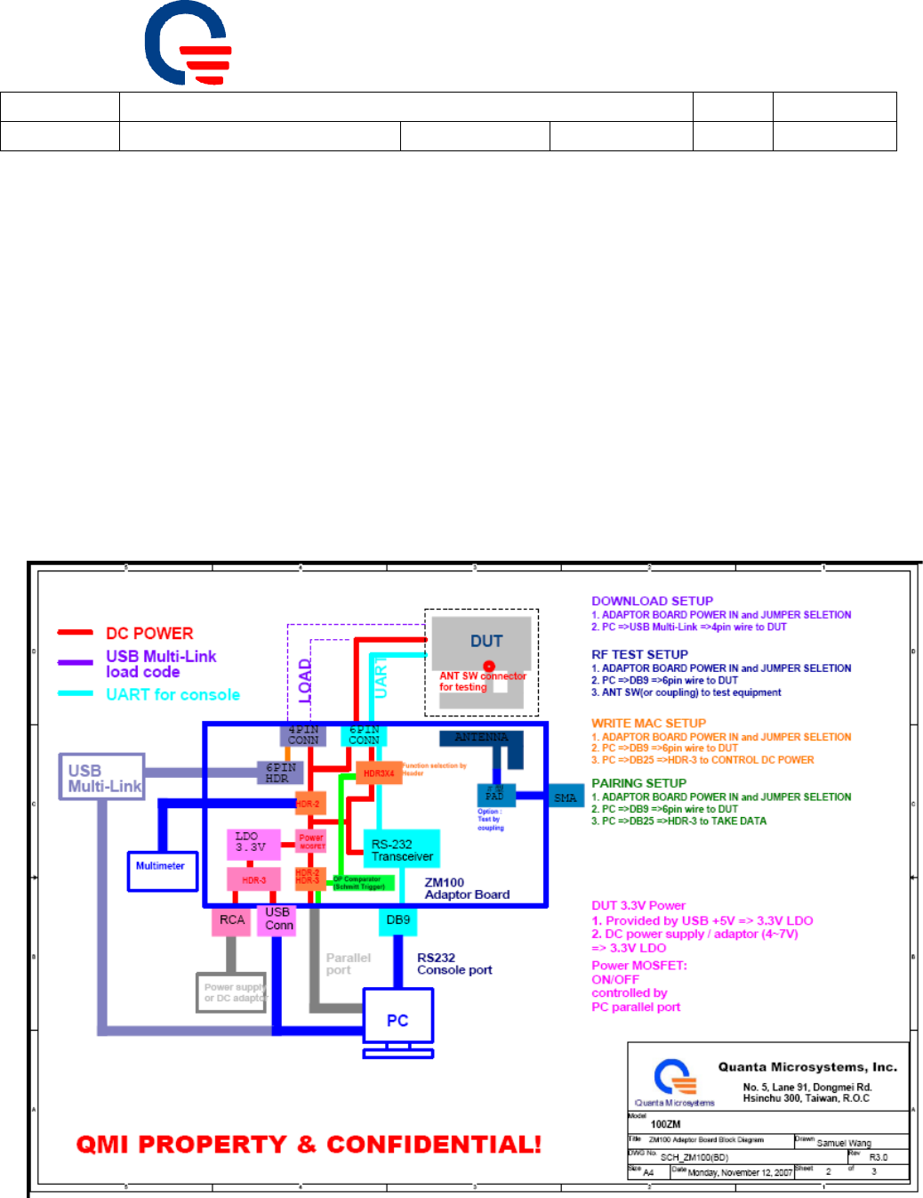
1. Adaptor board connection and setup
Power IN (+2.7~+3.3Vdc)
USB plug in:
― J_USB should be selected as USB PWR IN mode
― USB +5V Æ LDOÆPower in
RCA Jack plug in:
― J_DC should be 2-3 pin short.
― Use a +4~7V(inner) DC adaptor plug in CON_RCAÆ LDOÆPower in
Pin header plug in:
― Use other power source(such as power supply)
― Supply +2.7~+3.3V and plug in by J_3V pin headerÆPower in
Fig1.1 Adaptor board and DUT test setup
Quanta Microsystems, Inc.
Subject: ZM10 operation manual-RF mode Rev: 0.2
Doc No. OP_ZM10X-1 Revised Date: 2008/03/28 Page: 4 of 10
QMI PROPERTY & CONFIDENTIAL!
4
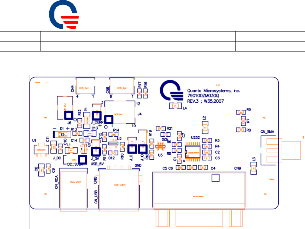
Adaptor board placement and jumper selection
J_CURRENT: For DC current measurement use; Default is short by Jumper.
J_DC: DC input selection
― 1-2 Short by Jumper : Use USB +5VÆLDOÆ3.3V
― 2-3 Short by Jumper : Use RCA Jack
― Open : Use J_3V pin header
CN USB: Insert USB A-type cable connect to USB host to provide +5Vdc.
CN_RCA : Provide +4~7Vdc by RCA Jack.
J_3V : Provide +2.7~3.3V by pin header, positive port are marked in square.
CN9 : D-SUB9 for UART console.
CON4 : insert 4-wire cable connect to DUT for FW download.
CON6 : insert 6-wire cable connect to DUT for RF testing.
Quanta Microsystems, Inc.
Subject: ZM101 operation manual-RF mode Rev: 0.2
Doc No. OP_ZM10X-1 Revised Date: 2008/03/28 Page: 5 of 10
QMI PROPERTY & CONFIDENTIAL!
5
FW download
Connect 4pin connector to adaptor and use USB multi-link or programmer
download, 2X3 pin header pin1 are marked in square.
Open OS hyper terminal as a com port used
UART connection
Use a D-SUB9 cable connects to PC com port
Open OS hyper terminal as a com port used
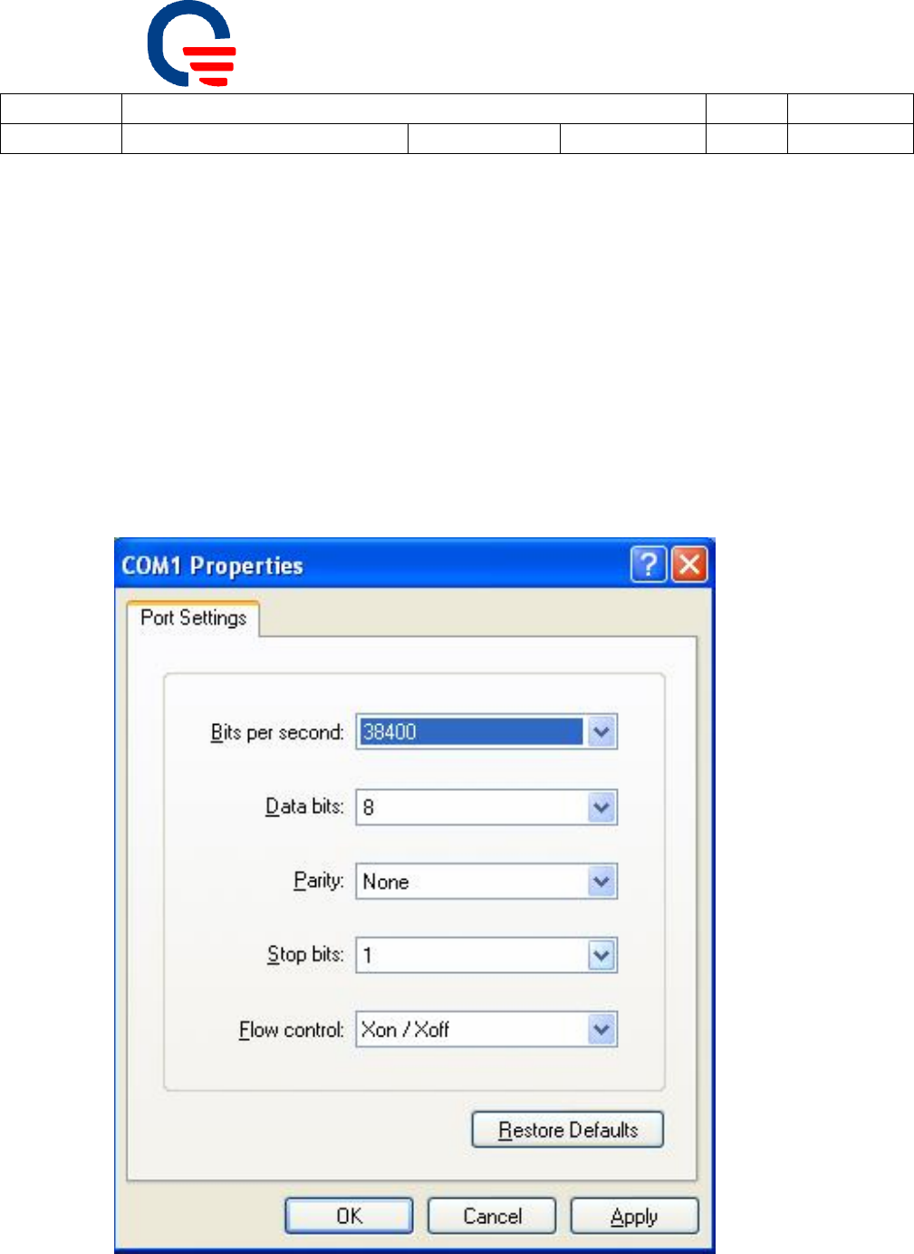
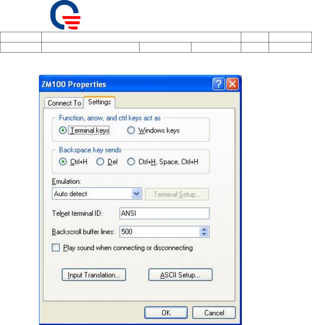
Set properties as following
Fig 1.1 Hyper terminal COM port settings
Quanta Microsystems, Inc.
Subject: ZM101 operation manual-RF mode Rev: 0.2
Doc No. OP_ZM10X-1 Revised Date: 2008/03/28 Page: 6 of 10
QMI PROPERTY & CONFIDENTIAL!
6
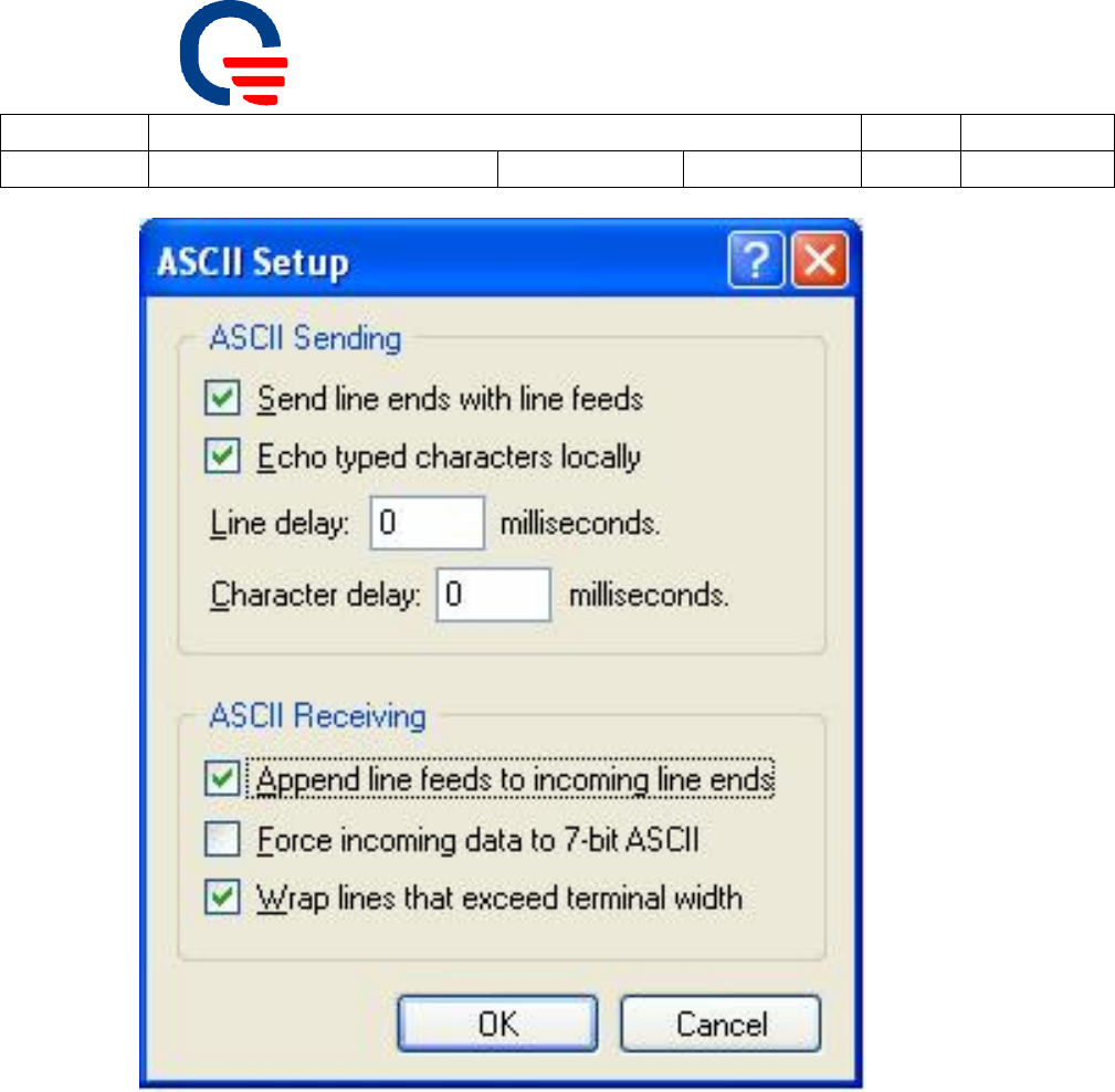
Fig 1.2 Hyper terminal Properties settings
Quanta Microsystems, Inc.
Subject: ZM101 operation manual-RF mode Rev: 0.2
Doc No. OP_ZM10X-1 Revised Date: 2008/03/28 Page: 7 of 10
QMI PROPERTY & CONFIDENTIAL!
7
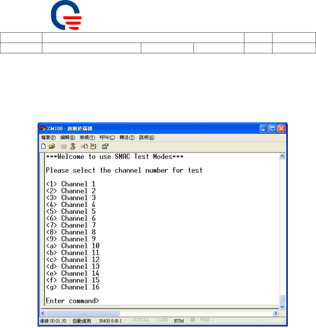
Fig 1.3 ASCII setup
After finished above item, connect DUT and adaptor board by 6pin wire connection.
Then it will be operating as RF test mode
Quanta Microsystems, Inc.
Subject: ZM101 operation manual-RF mode Rev: 0.2
Doc No. OP_ZM10X-1 Revised Date: 2008/03/28 Page: 8 of 10
QMI PROPERTY & CONFIDENTIAL!
8
2. RF test mode application
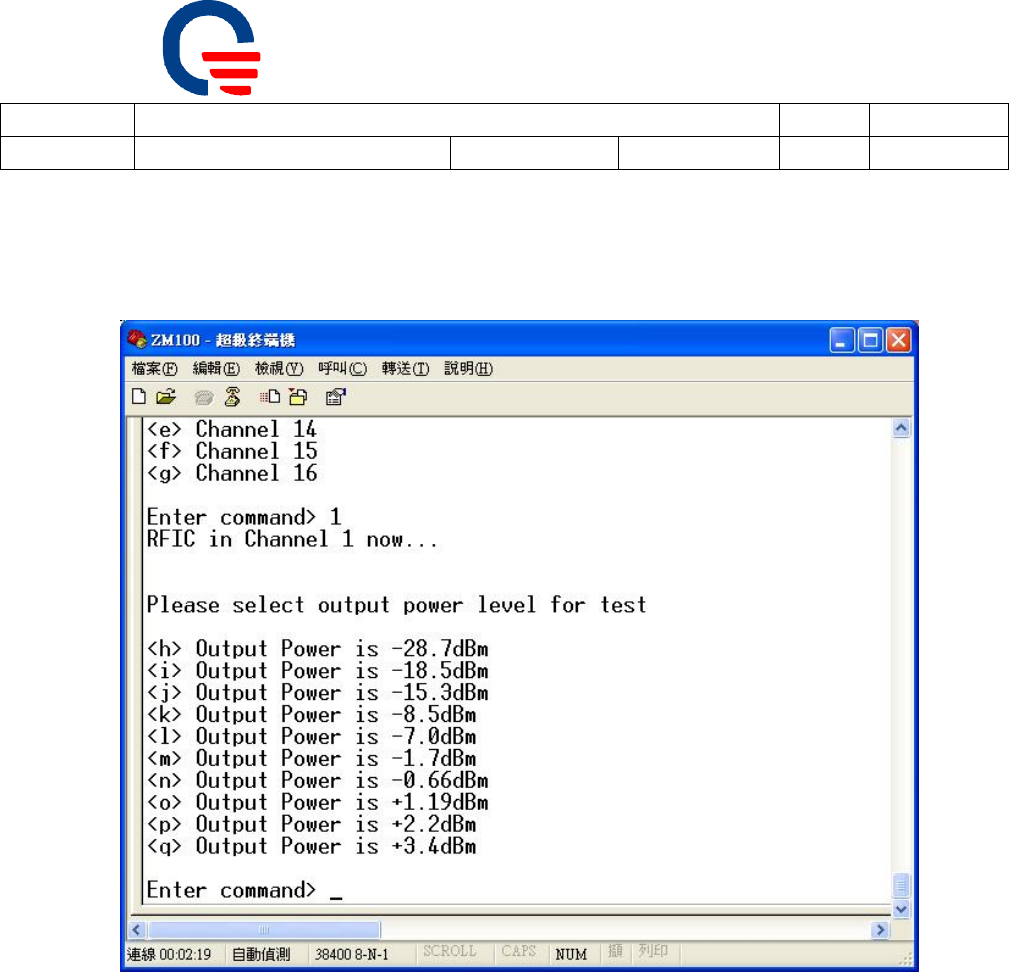
Channel selection
Set channel
― Select character “1,2,3….,f,g to set channel 1~16
Quanta Microsystems, Inc.
Subject: ZM101 operation manual-RF mode Rev: 0.2
Doc No. OP_ZM10X-1 Revised Date: 2008/03/28 Page: 9 of 10
QMI PROPERTY & CONFIDENTIAL!
9
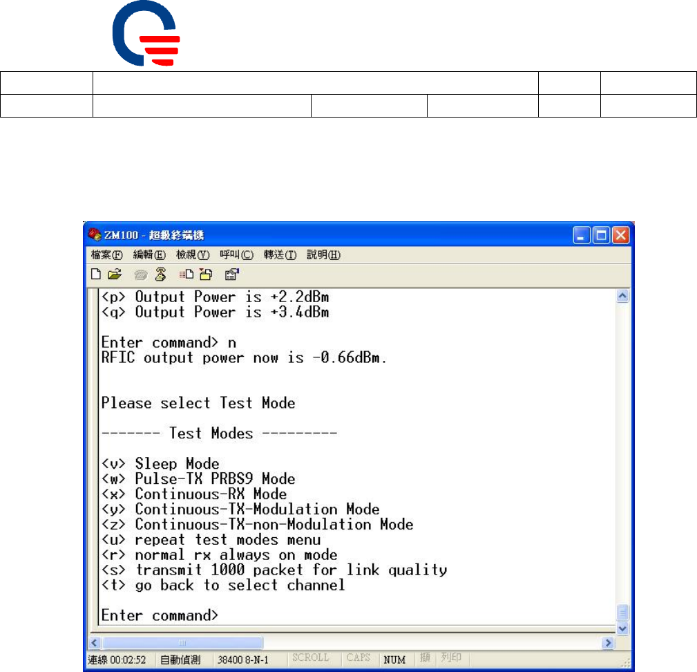
Set output power
― Default power: -0.66dBm (select character “n”)
Quanta Microsystems, Inc.
Subject: ZM101 operation manual-RF mode Rev: 0.2
Doc No. OP_ZM10X-1 Revised Date: 2008/03/28 Page: 10 of 10
QMI PROPERTY & CONFIDENTIAL!
10
Set operation mode
― Select character “v,w,x…r,s” for operation mode
After you finished testing, you can select character “t” to go back to main
manual. If you can not go back to main manual (ex. DUT on sleep mode); it shall
be power off then power on DUT to go back to main manual.

11
Federal Communication Commission Interference Statement
This equipment has been tested and found to comply with the limits for a Class B digital
device, pursuant to Part 15 of the FCC Rules. These limits are designed to provide
reasonable protection against harmful interference in a residential installation. This
equipment generates, uses and can radiate radio frequency energy and, if not installed
and used in accordance with the instructions, may cause harmful interference to radio
communications. However, there is no guarantee that interference will not occur in a
particular installation. If this equipment does cause harmful interference to radio or
television reception, which can be determined by turning the equipment off and on, the
user is encouraged to try to correct the interference by one of the following measures:
- Reorient or relocate the receiving antenna.
- Increase the separation between the equipment and receiver.
- Connect the equipment into an outlet on a circuit different from that to which the
receiver is connected.
- Consult the dealer or an experienced radio/TV technician for help.
FCC Caution: Any changes or modifications not expressly approved by the party
responsible for compliance could void the user's authority to operate this equipment.
This device complies with Part 15 of the FCC Rules. Operation is subject to the
following two conditions: (1) This device may not cause harmful interference, and (2)
this device must accept any interference received, including interference that may
cause undesired operation.
FCC Radiation Exposure Statement:
This equipment complies with FCC radiation exposure limits set forth for an
uncontrolled environment. This equipment should be installed and operated with
minimum distance 20cm between the radiator & your body. This transmitter must not
be co-located or operating in conjunction with any other antenna or transmitter.
This device is intended only for OEM integrators under the following conditions:
1. The antenna must be installed such that 20 cm is maintained between the
antenna and users, and
2. The transmitter module may not be co-located with any other transmitter or
antenna,
IMPORTANT NOTE: In the event that these conditions can not be met (for example
certain laptop configurations or co-location with another transmitter), then the FCC
authorization is no longer considered valid and the FCC ID can not be used on the final
product. In these circumstances, the OEM integrator will be responsible for
re-evaluating the end product (including the transmitter) and obtaining a separate FCC
authorization.

12
End Product Labeling
This transmitter module is authorized only for use in device where the antenna may be
installed such that 20 cm may be maintained between the antenna and users. The
final end product must be labeled in a visible area with the following: “Contains
FCC ID:T5U-ZM101”.
Manual Information To the End User
The OEM integrator has to be aware not to provide information to the end user
regarding how to install or remove this RF module in the user’s manual of the end
product which integrates this module.
The end user manual shall include all required regulatory information/warning as show
in this manual.