Quantum Data 802Bt Users Manual Ug
802BT to the manual f5df4673-df5d-48e7-8517-1bfea67e2818
2015-02-05
: Quantum-Data Quantum-Data-802Bt-Users-Manual-492762 quantum-data-802bt-users-manual-492762 quantum-data pdf
Open the PDF directly: View PDF ![]() .
.
Page Count: 744 [warning: Documents this large are best viewed by clicking the View PDF Link!]
- User Guide
- Contents
- 1 Getting Started
- 2 Testing Video Displays
- General video display testing procedure
- Testing analog computer (IT) CRTs
- Testing digital computer (IT) FPDs
- Testing analog composite video SDTV (CE) CRTs
- Testing analog component video SDTV (CE) CRTs
- Testing digital component video HDTV (CE) flat panel displays
- 3 Administrative Tasks
- 4 Working with Formats
- Overview
- Format library
- Format naming conventions
- Creating custom formats
- Editing Format knob lists
- Configuring DCS priority scheme
- Creating format aliases
- 5 Working with Images
- 6 Working with Test Sequences
- 7 Using GPIB Interface
- 8 Analyzing Digital Sources and Cables
- Getting started
- Measuring timing of video signal
- Testing cables and distribution systems
- Measuring pixel errors
- Testing InfoFrames (HDMI only)
- Testing audio (HDMI only)
- Controlling analyzer using command-line interface
- Generating pseudo-random noise from your device
- 9 Testing HDMI Sink Devices
- 10 Testing EDID
- 11 Testing HDCP
- 12 Using Special Sync Output
- A Command Reference
- Commands by name
- *CLS
- *DDT
- *ESE
- *ESR?
- *IDN?
- *OPC
- *RST
- *SRE
- *STB
- *TRG
- *TST
- *WAI
- ADDR
- ADOT
- ALIK
- ALIN
- ALIQ?
- ALLE
- ALLU
- AMAP
- ANIG
- ANIM?
- ANTI
- ARAT
- AROW
- ASBG
- ASCT
- ASGG
- ASRG
- ASSC
- ASSG
- ASSS
- AVCM
- AVCO
- AVCS
- AVPG
- AVPS
- AVSS
- AVST
- BALG
- BASE
- BLUG
- BOIT
- BOOT
- BRAT
- CACH
- CALF
- CALL
- CENT
- CROS
- CSPG
- CSPP
- CTLM
- CXAR
- DACA
- DACG
- DADG
- DALS
- DASI
- DAST
- DAXA
- DAXG
- DCBM
- DCEX
- DCPG
- DCPX?
- DCRD?
- DDCV?
- DELX
- DELY
- DIRA
- DIRB
- DIRE
- DIRK
- DIRL
- DIRN
- DIRP
- DIRQ?
- DIRS
- DMAP
- DNUM
- DPGU
- DPTG
- DPTR
- DSCT
- DSST
- DVIC
- DVPT
- DVQM
- DVSC
- DVSI
- DVSM
- DVSP
- DVSS
- DVST
- DWEL
- EDID?
- EQUA
- EQUB
- EQUF
- ERRC
- ERRQ?
- ERRY?
- EXAR
- EXCX
- FDTA
- FLSH
- FMTA
- FMTB
- FMTE
- FMTG?
- FMTJ
- FMTK
- FMTL
- FMTN
- FMTP
- FMTQ?
- FMTR
- FMTS
- FMTU
- FMTZ
- FORM
- FRAT?
- FRGB
- FSPD
- FSPG
- FSPP
- FSPW
- GAMA
- GAMC
- GCET?
- GETA?
- GETR?
- GFED?
- GLUT
- GMAP
- GNPT?
- GPEL?
- GPER?
- GPIB
- GRID
- GRIH
- GRIV
- GRNG
- GTLS
- HATI
- HATO
- HDCP?
- HDMI
- HRAT
- HRES
- HSIZ
- HSPD
- HSPG
- HSPP
- HSPW
- HSRS
- HSSC
- HTOT
- HVPD?
- HVSA
- I2CR?
- I2CW
- IDET
- IFGU
- IFTG
- IFTR
- IMGA
- IMGB
- IMGE
- IMGK
- IMGL
- IMGN
- IMGP
- IMGQ?
- IMGR
- IMGS
- IMGU
- INIT
- ISTP?
- ISUB
- IVER
- JDVI
- JLDI
- JRAT
- KEYY
- KNOB
- LCDS?
- LEDS?
- LIMI
- LINE
- LLOS
- LMAX
- LMAX
- LMIN
- LSPG
- LSPP
- LUTA
- LUTB
- LUTE
- LUTK
- LUTL
- LUTN
- LUTQ?
- LUTS
- LUTU
- MAPA
- MAPB
- MAPE
- MAPK
- MAPL
- MAPN
- MAPQ?
- MAPS
- MEMC
- MEMF?
- MEML?
- MEMT
- MMAP
- MODE
- MSIZ
- MUTE
- NAMF?
- NAMI
- NAMK
- NAMQ?
- NAMY
- NBPA
- NBPC
- NCPP
- NDAC
- NDAS
- NERR?
- NLNK
- NOGA
- NOTU
- NPPP
- NSTP?
- OERR?
- OFFX
- OFFY
- OUTG
- OVAL
- PAGE
- PCPG
- PDAU
- PDSH
- PDSW
- PDSX
- PDSY
- PELD
- PENH
- PENW
- PKUP
- PNAU
- PNGU
- PNSA
- PNSF
- PNSG
- PNSL
- PNSM
- PNSP
- PNSS
- PNST
- PREG
- PSHD
- PSPG
- PSPM
- PSPP
- PSPW
- PSVD
- PUTA
- PUTR
- PXAR?
- RATC
- RCTL
- RECT
- REDG
- RFLD
- RGBQ?
- RGBW
- RMAP
- ROWI
- ROWQ?
- ROWY
- SAMP
- SCAL
- SCAN
- SCTL
- SDIR
- SDLY
- SDMG
- SEOS
- SEQA
- SEQB
- SEQE
- SEQK
- SEQL
- SEQN
- SEQP
- SEQQ?
- SEQR
- SEQS
- SEQU
- SIZE
- SLUT
- SMAX?
- SMIN?
- SMOD
- SNUM
- SPAX
- SPAY
- SRAT
- SROP
- SSST
- STRG
- STEP
- SVSG
- SXAR
- SXCX
- SXEX
- TBOX
- TBXG
- TEXT
- TMAU
- TOBL
- TRIA
- TTLL
- UIDN
- UNPK
- USIZ
- UNPK
- UNPK
- VERF?
- VERG?
- VERH?
- VRAT?
- VRES
- VSIZ
- VSPD
- VSPG
- VSPP
- VSPW
- VTOF
- VTOT
- XACR
- XAFD
- XAUD
- XAVI
- XBBH
- XDID
- XGCP
- XGDP
- XGIF
- XLBW
- XMPG
- XRBW
- XRES
- XSPD
- XTBH
- XVSG
- YMDI
- YMDO
- YRES
- Commands by name
- B Image Reference
- Standard image descriptions
- Acer1
- Acer2
- Acer3, Acer4, Acer5 and Acer6
- Acer7 and Acer8
- Acer9
- AFDtest
- Analyzer
- AnsiLght
- Apple1
- Audio LR, AudioLRf, AudioRAT, Audio_L, Audio_Lf, Audio_R, Audio_Rf
- BarBlack
- BLU_EM, GRN_EM, RED_EM, WHT_EM, MEME1111, MEMESony, MESony_B, MESony_G, and MESony_R
- BLU_EM+, GRN_EM+, RED_EM+, WHT_EM+, MEMEPlus, MEPlus_B, MEPlus_G, and MEPlus_R
- BLU_PIC, GRAY_PIC, GRN_PIC, RED_PIC, WHT_PIC
- Bosch
- Box_50mm, Box_64mm, Box100mm, Box150mm, Box200mm, Box250mm
- BriteBox
- Burst (TV formats only)
- BurstTCE
- CardBMP
- Check511
- CheckBy3
- Check_02
- Check_11
- CirclesL
- CirclesS
- ColorBar
- ComFocus
- Cubes
- Custom
- DeltaErr
- Diamond1
- Dot1606, Dot1610, Dot1612, Dot1615, Dot1812, Dot1815, Dot2016
- Dot_10, Dot_12, Dot_24
- DV_Swing
- Dyna
- EdidData
- Elbit
- EMITest1, EMITest2, EMITest3, EMITest4, EMITest5
- FlashGry
- FlashRGB
- Flat, Flat07, Flat13, Flat20, Flat27, Flat33, Flat40, Flat47, Flat53, Flat60, Flat67, Flat73, Flat80, Flat87, Flat93, FlatGray, ...
- Flat_B, Flat_G, Flat_R
- Focus20
- FocusC14
- FocusCCx
- FocusEM
- FocusEMP
- FocusM00 - FocusM15
- Focus_@6, Focus_@7, Focus_@8, Focus_@9
- Focus_Cx
- Focus_H
- Focus_MM
- Focus_Oo
- Format
- FormatRx
- GenOps
- GenStats
- Geom_1 - Geom_5
- Gray25, Gray40
- GrayBar
- GrayL1, GrayL3
- Grays5, Grays9, Grays11, Grays16, Grays32, Grays64
- GraysAll
- Grill_11, Grill_15, Grill_22, Grill_33, Grill_44
- HalfArea
- HalfClk
- Hat1606, Hat1610, Hat1612, Hat1615
- Hat1606A, Hat1610A, Hat1612A, Hat1615A
- Hat1812, Hat1815
- Hat1812A, Hat1815A
- Hat2016
- Hat2016A
- Hatch_6, Hatch_10i, Hatch_10o, Hatch_12i, Hatch_12o, Hatch_24i, Hatch_24o, Hatch_24s, Hatch_G, Hatch_M, GRN_HTCH, and MAGENTA
- Hatch_16, Hatch_20
- Hatch20
- Hatch4x3, Hatch5x4 and Hatch8x8
- Hatch64W
- HdcpA1B1, HdcpA1B2, HdcpA2B1, HdcpA2B2, HdcpProd
- Hitachi1
- HSVnRGB
- Imex1
- InFocus1
- InFocus2
- KanjiKAN
- LGLCDTVB, LGLCDTVG, LGLCDTVR, LGLCDTVW
- LGRamp
- Linearty (Linearity)
- LinFocus
- Master
- MoireX, MoireX33, MoireY, MoireY33
- Monoscop
- MSony7, MSony8
- MulBurst
- Orion
- Outline0, Outline1, Outline2, Outline3
- P1
- P2
- P3
- P4
- P5
- P6
- P6_Sony
- P7
- P8
- P9
- P10
- PacketRx
- PacketTx
- PdsCrt1
- PdsCrt2
- Persist
- PgBar64H, PgBar64V
- PgCB, PgCG, PgCR, PgCW, PgCWrgb
- Philips1
- PixelRep
- PRN24bit
- PRN_5, PRN_9
- PulseBar
- QuartBox
- Ramp
- RampX
- Ramp_B, Ramp_G, and Ramp_R
- Raster
- Regulate
- Samsung1, Samsung2
- Samsung3
- Samsung4
- Samsung5
- Samsung6
- SamsungB
- SamsungT
- SlideBox
- SlideX
- SMPTE133
- SMPTEbar
- Sony6
- Sony6WLC
- sRGBflat
- Staircas, Stairs20
- Strokes0, Strokes1
- Text_9, Text_9T, Text_11, Text_12T, Text_16
- TintAlign
- Toshiba
- TVBar100 & TVBar_75 (TV formats only)
- Taffeta
- TVoutLin
- TVSplBar
- Standard image descriptions
- C Error Messages
- System errors
- Format errors
- Error code descriptions
- 2000-2999 Format errors
- 2030
- 2040
- 2041
- 2050
- 2060
- 2071
- 2072
- 2073
- 2074
- 2075
- 2076
- 2077
- 2078
- 2079
- 2080
- 2082
- 2083
- 2084
- 2085
- 2090
- 2091
- 2092
- 2093
- 2094
- 2096
- 2097
- 2098
- 2099
- 2130
- 2140
- 2141
- 2150
- 2151
- 2152
- 2155
- 2180
- 2181
- 2190
- 2191
- 2200
- 2201
- 2205
- 2206
- 2207
- 2208
- 2230
- 2231
- 2240
- 2250
- 2270
- 2280
- 2300
- 2310
- 2320
- 2321
- 2330
- 2350
- 2370
- 2390
- 2391
- 2392
- 2393
- 2394
- 2395
- 2396
- 2397
- 2398
- 2399
- 2400
- 2401
- 2405
- 2406
- 2407
- 2408
- 2409
- 2410
- 2425
- 2430
- 2450
- 2465
- 2466
- 2490
- 2495
- 2496
- 2550
- 2551
- 2553
- 2554
- 2555
- 2704
- 2705
- 2706
- 2714
- 2715
- 2716
- 2717
- 2719
- 2720
- 2721
- 2722
- 2741
- 2742
- 2743
- 2745
- 2747
- 2748
- 2760
- 2761
- 2762
- 2800
- 2801
- 2802
- 2803
- 2804
- 2805
- 2806
- 3000-3999 Image errors
- 4000-4999 Test sequence errors
- 5000-5999 Directory errors
- 6000-6999 Bitmap errors
- 7000-7999 LUT errors
- 8000-8999 Font errors
- 9000-9999 System errors
- 10000-10999 System errors
- 2000-2999 Format errors

802BT/802R Video Test
Generator
User Guide
802BT/802R Video Test Generator, User Guide, Revision A.5 (12/22/04)
Copyright 2004 Quantum Data. All rights reserved.
The information in this document is provided for use by our customers and may not be incorporated into other products or publications without the
expressed written consent of Quantum Data. Quantum Data reserves the right to make changes to its products to improve performance, reliability,
producibility, and (or) marketability. Information furnished by Quantum Data is believed to be accurate and reliable. However, no responsibility is assumed
by Quantum Data for its use.
Updates to this manual are available at http://www.quantumdata.com/support/downloads/.
802BT/802R Video Test Generator User Guide i
Contents
Chapter 1 Getting Started
Product overview. . . . . . . . . . . . . . . . . . . . . . . . . . . . . . . . . . . . . . . . . . . . . . . . . . . . . . . . 2
Standard features . . . . . . . . . . . . . . . . . . . . . . . . . . . . . . . . . . . . . . . . . . . . . . . . . . . . 2
Optional features . . . . . . . . . . . . . . . . . . . . . . . . . . . . . . . . . . . . . . . . . . . . . . . . . . . . 2
Physical controls. . . . . . . . . . . . . . . . . . . . . . . . . . . . . . . . . . . . . . . . . . . . . . . . . . . . . 4
Power switch . . . . . . . . . . . . . . . . . . . . . . . . . . . . . . . . . . . . . . . . . . . . . . . . . . . . 4
Format knob . . . . . . . . . . . . . . . . . . . . . . . . . . . . . . . . . . . . . . . . . . . . . . . . . . . . . 4
Image knob . . . . . . . . . . . . . . . . . . . . . . . . . . . . . . . . . . . . . . . . . . . . . . . . . . . . . 5
Image Step key . . . . . . . . . . . . . . . . . . . . . . . . . . . . . . . . . . . . . . . . . . . . . . . . . . 5
R, G, B Video Gate keys . . . . . . . . . . . . . . . . . . . . . . . . . . . . . . . . . . . . . . . . . . . 6
ACS, DCS, and DSS Sync Gate keys . . . . . . . . . . . . . . . . . . . . . . . . . . . . . . . . . 6
Outputs Key . . . . . . . . . . . . . . . . . . . . . . . . . . . . . . . . . . . . . . . . . . . . . . . . . . . . . 7
LCD . . . . . . . . . . . . . . . . . . . . . . . . . . . . . . . . . . . . . . . . . . . . . . . . . . . . . . . . . . . 7
Video interfaces . . . . . . . . . . . . . . . . . . . . . . . . . . . . . . . . . . . . . . . . . . . . . . . . . . . . . . . . 9
VGA interface. . . . . . . . . . . . . . . . . . . . . . . . . . . . . . . . . . . . . . . . . . . . . . . . . . . . 9
DVI-I interface . . . . . . . . . . . . . . . . . . . . . . . . . . . . . . . . . . . . . . . . . . . . . . . . . . . 9
LVDS interface . . . . . . . . . . . . . . . . . . . . . . . . . . . . . . . . . . . . . . . . . . . . . . . . . . 10
Special Sync (S/S) interface . . . . . . . . . . . . . . . . . . . . . . . . . . . . . . . . . . . . . . . 10
S-Video interface . . . . . . . . . . . . . . . . . . . . . . . . . . . . . . . . . . . . . . . . . . . . . . . . 10
Composite video BNC . . . . . . . . . . . . . . . . . . . . . . . . . . . . . . . . . . . . . . . . . . . . 11
Component video BNC interface . . . . . . . . . . . . . . . . . . . . . . . . . . . . . . . . . . . . 11
Computer interfaces . . . . . . . . . . . . . . . . . . . . . . . . . . . . . . . . . . . . . . . . . . . . . . . . . . . . 12
RS-232 interface . . . . . . . . . . . . . . . . . . . . . . . . . . . . . . . . . . . . . . . . . . . . . . . . 12
GPIB interface (optional) . . . . . . . . . . . . . . . . . . . . . . . . . . . . . . . . . . . . . . . . . . 12
ii Contents
USB interface . . . . . . . . . . . . . . . . . . . . . . . . . . . . . . . . . . . . . . . . . . . . . . . . . . . 12
PCMCIA interface. . . . . . . . . . . . . . . . . . . . . . . . . . . . . . . . . . . . . . . . . . . . . . . . . . . 13
Command interfaces . . . . . . . . . . . . . . . . . . . . . . . . . . . . . . . . . . . . . . . . . . . . . . . . . . . . 14
Setting up a terminal connection with the generator. . . . . . . . . . . . . . . . . . . . . . . . . 14
Changing the baud rate . . . . . . . . . . . . . . . . . . . . . . . . . . . . . . . . . . . . . . . . . . . . . . 15
Sending commands interactively . . . . . . . . . . . . . . . . . . . . . . . . . . . . . . . . . . . . . . . 15
Sending commands from text files . . . . . . . . . . . . . . . . . . . . . . . . . . . . . . . . . . . . . . 16
Special operating modes. . . . . . . . . . . . . . . . . . . . . . . . . . . . . . . . . . . . . . . . . . . . . . . . . 18
Summary of special modes . . . . . . . . . . . . . . . . . . . . . . . . . . . . . . . . . . . . . . . . . . . 19
Special key operations summary . . . . . . . . . . . . . . . . . . . . . . . . . . . . . . . . . . . . . . . 20
About Video Generator Manager . . . . . . . . . . . . . . . . . . . . . . . . . . . . . . . . . . . . . . . . . . 21
VGM features . . . . . . . . . . . . . . . . . . . . . . . . . . . . . . . . . . . . . . . . . . . . . . . . . . . . . . 21
Installing VGM . . . . . . . . . . . . . . . . . . . . . . . . . . . . . . . . . . . . . . . . . . . . . . . . . . . . . 22
Chapter 2 Testing Video Displays
General video display testing procedure. . . . . . . . . . . . . . . . . . . . . . . . . . . . . . . . . . . . . 24
Making physical connections . . . . . . . . . . . . . . . . . . . . . . . . . . . . . . . . . . . . . . . . . . 24
Setting the video output mode . . . . . . . . . . . . . . . . . . . . . . . . . . . . . . . . . . . . . . . . . 24
Selecting video formats . . . . . . . . . . . . . . . . . . . . . . . . . . . . . . . . . . . . . . . . . . . . . . 25
Selecting formats automatically . . . . . . . . . . . . . . . . . . . . . . . . . . . . . . . . . . . . . 25
Selecting formats manually . . . . . . . . . . . . . . . . . . . . . . . . . . . . . . . . . . . . . . . . 26
Understanding the format library . . . . . . . . . . . . . . . . . . . . . . . . . . . . . . . . . . . . . . . 26
Organization of format library. . . . . . . . . . . . . . . . . . . . . . . . . . . . . . . . . . . . . . . 26
Viewing format parameters . . . . . . . . . . . . . . . . . . . . . . . . . . . . . . . . . . . . . . . . 28
Selecting images . . . . . . . . . . . . . . . . . . . . . . . . . . . . . . . . . . . . . . . . . . . . . . . . . . . 28
Testing analog computer (IT) CRTs . . . . . . . . . . . . . . . . . . . . . . . . . . . . . . . . . . . . . . . . 31
Testing digital computer (IT) FPDs . . . . . . . . . . . . . . . . . . . . . . . . . . . . . . . . . . . . . . . . . 34
Testing analog composite video SDTV (CE) CRTs . . . . . . . . . . . . . . . . . . . . . . . . . . . . 36
Testing analog component video SDTV (CE) CRTs . . . . . . . . . . . . . . . . . . . . . . . . . . . . 38
Testing digital component video HDTV (CE) flat panel displays. . . . . . . . . . . . . . . . . . . 40
Chapter 3 Administrative Tasks
Displaying system information . . . . . . . . . . . . . . . . . . . . . . . . . . . . . . . . . . . . . . . . . . . . 44
Restoring factory settings . . . . . . . . . . . . . . . . . . . . . . . . . . . . . . . . . . . . . . . . . . . . . . . . 45
Setting and restoring system parameters . . . . . . . . . . . . . . . . . . . . . . . . . . . . . 45
802BT/802R Video Test Generator User Guide iii
Calibrating the generator. . . . . . . . . . . . . . . . . . . . . . . . . . . . . . . . . . . . . . . . . . . . . . . . . 47
Calibrating frequency . . . . . . . . . . . . . . . . . . . . . . . . . . . . . . . . . . . . . . . . . . . . . . . . 48
Cloning generators . . . . . . . . . . . . . . . . . . . . . . . . . . . . . . . . . . . . . . . . . . . . . . . . . . . . . 49
Installing firmware . . . . . . . . . . . . . . . . . . . . . . . . . . . . . . . . . . . . . . . . . . . . . . . . . . . . . . 50
Memory management . . . . . . . . . . . . . . . . . . . . . . . . . . . . . . . . . . . . . . . . . . . . . . . . . . . 51
Chapter 4 Working with Formats
Overview . . . . . . . . . . . . . . . . . . . . . . . . . . . . . . . . . . . . . . . . . . . . . . . . . . . . . . . . . . . . . 54
Format library . . . . . . . . . . . . . . . . . . . . . . . . . . . . . . . . . . . . . . . . . . . . . . . . . . . . . . . . . 55
Compatibility . . . . . . . . . . . . . . . . . . . . . . . . . . . . . . . . . . . . . . . . . . . . . . . . . . . . . . . 55
Format naming conventions . . . . . . . . . . . . . . . . . . . . . . . . . . . . . . . . . . . . . . . . . . . . . . 56
Composite television format names . . . . . . . . . . . . . . . . . . . . . . . . . . . . . . . . . . . . . 56
Component television format names . . . . . . . . . . . . . . . . . . . . . . . . . . . . . . . . . . . . 57
Computer display format names. . . . . . . . . . . . . . . . . . . . . . . . . . . . . . . . . . . . . . . . 58
Aperture designators . . . . . . . . . . . . . . . . . . . . . . . . . . . . . . . . . . . . . . . . . . . . . . . . 59
Using legacy format names . . . . . . . . . . . . . . . . . . . . . . . . . . . . . . . . . . . . . . . . . . . 60
Viewing the format library . . . . . . . . . . . . . . . . . . . . . . . . . . . . . . . . . . . . . . . . . . . . . 61
Viewing format details. . . . . . . . . . . . . . . . . . . . . . . . . . . . . . . . . . . . . . . . . . . . . . . . 61
Creating custom formats . . . . . . . . . . . . . . . . . . . . . . . . . . . . . . . . . . . . . . . . . . . . . . . . . 63
Determining the signal specifications of the display . . . . . . . . . . . . . . . . . . . . . . . . . 63
Creating custom formats using the command line interface. . . . . . . . . . . . . . . . . . . 63
Creating a new format . . . . . . . . . . . . . . . . . . . . . . . . . . . . . . . . . . . . . . . . . . . . 63
Creating a format based on an existing format . . . . . . . . . . . . . . . . . . . . . . . . . 64
Modifying existing formats . . . . . . . . . . . . . . . . . . . . . . . . . . . . . . . . . . . . . . . . . 65
Editing Format knob lists. . . . . . . . . . . . . . . . . . . . . . . . . . . . . . . . . . . . . . . . . . . . . . . . . 67
Editing format knob list using internal editor . . . . . . . . . . . . . . . . . . . . . . . . . . . . . . . 67
Editing format knob list using command line interface . . . . . . . . . . . . . . . . . . . . . . . 69
Configuring DCS priority scheme . . . . . . . . . . . . . . . . . . . . . . . . . . . . . . . . . . . . . . . . . . 70
Creating format aliases . . . . . . . . . . . . . . . . . . . . . . . . . . . . . . . . . . . . . . . . . . . . . . . . . . 72
Chapter 5 Working with Images
Overview . . . . . . . . . . . . . . . . . . . . . . . . . . . . . . . . . . . . . . . . . . . . . . . . . . . . . . . . . . . . . 74
Viewing the image list. . . . . . . . . . . . . . . . . . . . . . . . . . . . . . . . . . . . . . . . . . . . . . . . 74
Creating custom images . . . . . . . . . . . . . . . . . . . . . . . . . . . . . . . . . . . . . . . . . . . . . . . . . 75
Command file example . . . . . . . . . . . . . . . . . . . . . . . . . . . . . . . . . . . . . . . . . . . 76
iv Contents
Downloading bitmap images from a PCMCIA card. . . . . . . . . . . . . . . . . . . . . . . . . . . . . 78
Looping through images . . . . . . . . . . . . . . . . . . . . . . . . . . . . . . . . . . . . . . . . . . . . . . . . . 80
Editing Image knob list . . . . . . . . . . . . . . . . . . . . . . . . . . . . . . . . . . . . . . . . . . . . . . . . . . 81
Editing image knob list using internal editor . . . . . . . . . . . . . . . . . . . . . . . . . . . . . . . 81
Editing Image knob list using command line interface . . . . . . . . . . . . . . . . . . . . . . . 82
Creating image aliases . . . . . . . . . . . . . . . . . . . . . . . . . . . . . . . . . . . . . . . . . . . . . . . . . . 84
Chapter 6 Working with Test Sequences
Overview . . . . . . . . . . . . . . . . . . . . . . . . . . . . . . . . . . . . . . . . . . . . . . . . . . . . . . . . . . . . . 86
Creating a test sequence . . . . . . . . . . . . . . . . . . . . . . . . . . . . . . . . . . . . . . . . . . . . . . . . 87
Creating a test sequence using command line. . . . . . . . . . . . . . . . . . . . . . . . . . . . . 87
Creating and editing test sequences using the internal editor . . . . . . . . . . . . . . . . . 88
Viewing the test sequence list. . . . . . . . . . . . . . . . . . . . . . . . . . . . . . . . . . . . . . . . . . . . . 92
Viewing the test sequence list using the command line . . . . . . . . . . . . . . . . . . . . . . 92
Deleting a test sequence using the command line . . . . . . . . . . . . . . . . . . . . . . . . . . 92
Viewing test sequence using internal sequence editor. . . . . . . . . . . . . . . . . . . . . . . 93
Running a sequence . . . . . . . . . . . . . . . . . . . . . . . . . . . . . . . . . . . . . . . . . . . . . . . . . . . . 94
Running a test sequence using the command line. . . . . . . . . . . . . . . . . . . . . . . . . . 94
Running a test sequence using internal sequence editor. . . . . . . . . . . . . . . . . . . . . 95
Cancelling the start-up sequence mode . . . . . . . . . . . . . . . . . . . . . . . . . . . . . . . . . . 96
Chapter 7 Using GPIB Interface
Overview . . . . . . . . . . . . . . . . . . . . . . . . . . . . . . . . . . . . . . . . . . . . . . . . . . . . . . . . . . . . . 98
Setting the GPIB port address . . . . . . . . . . . . . . . . . . . . . . . . . . . . . . . . . . . . . . . . . . . . 99
Queries and commands . . . . . . . . . . . . . . . . . . . . . . . . . . . . . . . . . . . . . . . . . . . . . . . . 100
Commands . . . . . . . . . . . . . . . . . . . . . . . . . . . . . . . . . . . . . . . . . . . . . . . . . . . . . . . 100
Queries . . . . . . . . . . . . . . . . . . . . . . . . . . . . . . . . . . . . . . . . . . . . . . . . . . . . . . . . . . 101
Sending commands and queries . . . . . . . . . . . . . . . . . . . . . . . . . . . . . . . . . . . . . . 102
Sending multiple commands and queries per line . . . . . . . . . . . . . . . . . . . . . . 102
Completion handshake . . . . . . . . . . . . . . . . . . . . . . . . . . . . . . . . . . . . . . . . . . 103
Input buffer . . . . . . . . . . . . . . . . . . . . . . . . . . . . . . . . . . . . . . . . . . . . . . . . . . . . 103
Status queries and control . . . . . . . . . . . . . . . . . . . . . . . . . . . . . . . . . . . . . . . . . . . . . . 104
Status byte . . . . . . . . . . . . . . . . . . . . . . . . . . . . . . . . . . . . . . . . . . . . . . . . . . . . . . . 104
Requesting service. . . . . . . . . . . . . . . . . . . . . . . . . . . . . . . . . . . . . . . . . . . . . . 104
Bus commands . . . . . . . . . . . . . . . . . . . . . . . . . . . . . . . . . . . . . . . . . . . . . . . . . . . . 106
802BT/802R Video Test Generator User Guide v
Remote/local operation . . . . . . . . . . . . . . . . . . . . . . . . . . . . . . . . . . . . . . . . . . 106
Chapter 8 Analyzing Digital Sources and Cables
Getting started. . . . . . . . . . . . . . . . . . . . . . . . . . . . . . . . . . . . . . . . . . . . . . . . . . . . . . . . 110
HDMI analyzer connections . . . . . . . . . . . . . . . . . . . . . . . . . . . . . . . . . . . . . . . . . . 110
Monitoring HDMI analyzer signal input . . . . . . . . . . . . . . . . . . . . . . . . . . . . . . 110
DVI analyzer connections . . . . . . . . . . . . . . . . . . . . . . . . . . . . . . . . . . . . . . . . . . . . 111
Starting the Analyzer Setup Utility . . . . . . . . . . . . . . . . . . . . . . . . . . . . . . . . . . . . . 112
Enabling and disabling analyzer images . . . . . . . . . . . . . . . . . . . . . . . . . . . . . 112
Measuring timing of video signal. . . . . . . . . . . . . . . . . . . . . . . . . . . . . . . . . . . . . . . . . . 114
Setting up analyzer to measure timing . . . . . . . . . . . . . . . . . . . . . . . . . . . . . . . . . . 114
Measuring basic timing parameters . . . . . . . . . . . . . . . . . . . . . . . . . . . . . . . . . . . . 115
Measuring detailed timing parameters . . . . . . . . . . . . . . . . . . . . . . . . . . . . . . . . . . 116
Testing cables and distribution systems . . . . . . . . . . . . . . . . . . . . . . . . . . . . . . . . . . . . 118
Testing accuracy of analyzer . . . . . . . . . . . . . . . . . . . . . . . . . . . . . . . . . . . . . . . . . 120
Measuring pixel errors. . . . . . . . . . . . . . . . . . . . . . . . . . . . . . . . . . . . . . . . . . . . . . . . . . 123
Setting delta error patch parameters . . . . . . . . . . . . . . . . . . . . . . . . . . . . . . . . . . . 123
Measuring pixel errors in patch. . . . . . . . . . . . . . . . . . . . . . . . . . . . . . . . . . . . . . . . 125
Testing InfoFrames (HDMI only) . . . . . . . . . . . . . . . . . . . . . . . . . . . . . . . . . . . . . . . . . . 127
Testing HDMI transmit device InfoFrame capability . . . . . . . . . . . . . . . . . . . . . . . . 127
Testing audio (HDMI only) . . . . . . . . . . . . . . . . . . . . . . . . . . . . . . . . . . . . . . . . . . . . . . 129
Testing HDMI transmit device audio capability. . . . . . . . . . . . . . . . . . . . . . . . . . . . 129
Controlling analyzer using command-line interface . . . . . . . . . . . . . . . . . . . . . . . . . . . 130
Signal timing analysis commands. . . . . . . . . . . . . . . . . . . . . . . . . . . . . . . . . . . . . . 130
Viewing signal timing parameters (on an HDMI/DVI monitor) . . . . . . . . . . . . . 130
Viewing specific timing parameters . . . . . . . . . . . . . . . . . . . . . . . . . . . . . . . . . 130
Pseudo-random noise generation commands . . . . . . . . . . . . . . . . . . . . . . . . . . . . 132
Generating pseudo-random noise . . . . . . . . . . . . . . . . . . . . . . . . . . . . . . . . . . 132
Pseudo-random noise analysis commands . . . . . . . . . . . . . . . . . . . . . . . . . . . . . . 132
Analyzing pseudo-random noise in a cable or distribution system . . . . . . . . . 133
Analyzing pseudo-random noise from an external source . . . . . . . . . . . . . . . . 134
Testing the analyzer. . . . . . . . . . . . . . . . . . . . . . . . . . . . . . . . . . . . . . . . . . . . . 134
Analyzing pixel data (delta error patch) . . . . . . . . . . . . . . . . . . . . . . . . . . . . . . 135
Generating pseudo-random noise from your device . . . . . . . . . . . . . . . . . . . . . . . . . . . 137
vi Contents
Implementing pseudo-random noise from your device. . . . . . . . . . . . . . . . . . . . . . 137
lfsr.h . . . . . . . . . . . . . . . . . . . . . . . . . . . . . . . . . . . . . . . . . . . . . . . . . . . . . . . . . 137
lfsl.cpp . . . . . . . . . . . . . . . . . . . . . . . . . . . . . . . . . . . . . . . . . . . . . . . . . . . . . . . 138
Sending pseudo-random noise to external device . . . . . . . . . . . . . . . . . . . . . . . . . 140
Analyzing noise from an external device . . . . . . . . . . . . . . . . . . . . . . . . . . . . . . . . 141
Setting pseudo-random noise parameters . . . . . . . . . . . . . . . . . . . . . . . . . . . . . . . 142
Chapter 9 Testing HDMI Sink Devices
Overview . . . . . . . . . . . . . . . . . . . . . . . . . . . . . . . . . . . . . . . . . . . . . . . . . . . . . . . . . . . . 146
Getting started. . . . . . . . . . . . . . . . . . . . . . . . . . . . . . . . . . . . . . . . . . . . . . . . . . . . . . . . 147
HDMI connections . . . . . . . . . . . . . . . . . . . . . . . . . . . . . . . . . . . . . . . . . . . . . . . . . 147
Setting up the generator for HDMI operation . . . . . . . . . . . . . . . . . . . . . . . . . . . . . 147
Testing HDMI video. . . . . . . . . . . . . . . . . . . . . . . . . . . . . . . . . . . . . . . . . . . . . . . . . . . . 149
Testing HDMI video formats . . . . . . . . . . . . . . . . . . . . . . . . . . . . . . . . . . . . . . . . . . 150
Testing HDMI video pixel repetition . . . . . . . . . . . . . . . . . . . . . . . . . . . . . . . . . . . . 152
Testing HDMI audio . . . . . . . . . . . . . . . . . . . . . . . . . . . . . . . . . . . . . . . . . . . . . . . . . . . 155
Testing 2-channel HDMI audio output from internal SPDIF source . . . . . . . . . . . . 155
Testing 8-channel HDMI audio output from internal source . . . . . . . . . . . . . . . . . . 157
Testing HDMI audio using an external audio source . . . . . . . . . . . . . . . . . . . . . . . 158
Testing HDMI InfoFrames . . . . . . . . . . . . . . . . . . . . . . . . . . . . . . . . . . . . . . . . . . . . . . . 161
Viewing InfoFrame contents . . . . . . . . . . . . . . . . . . . . . . . . . . . . . . . . . . . . . . . . . . 161
Testing with Active Format Description (AFD) . . . . . . . . . . . . . . . . . . . . . . . . . . . . 162
Chapter 10 Testing EDID
Overview . . . . . . . . . . . . . . . . . . . . . . . . . . . . . . . . . . . . . . . . . . . . . . . . . . . . . . . . . . . . 166
EDID testing for source devices . . . . . . . . . . . . . . . . . . . . . . . . . . . . . . . . . . . . . . . . . . 167
Testing response of source to EDID. . . . . . . . . . . . . . . . . . . . . . . . . . . . . . . . . . . . 167
EDID testing for sink devices . . . . . . . . . . . . . . . . . . . . . . . . . . . . . . . . . . . . . . . . . . . . 171
Viewing EDID from a display . . . . . . . . . . . . . . . . . . . . . . . . . . . . . . . . . . . . . . . . . 171
Writing EDID data to a display . . . . . . . . . . . . . . . . . . . . . . . . . . . . . . . . . . . . . . . . 172
Testing EDID in HDMI sink device for HDMI compliance . . . . . . . . . . . . . . . . . . . . 173
Overview of HDMI compliance testing . . . . . . . . . . . . . . . . . . . . . . . . . . . . . . . 173
Testing HDMI sink devices for EDID compliance. . . . . . . . . . . . . . . . . . . . . . . 174
Visual verification of formats . . . . . . . . . . . . . . . . . . . . . . . . . . . . . . . . . . . . . . 182
802BT/802R Video Test Generator User Guide vii
Chapter 11 Testing HDCP
Testing DVI or HDMI receiver with HDCP. . . . . . . . . . . . . . . . . . . . . . . . . . . . . . . . . . . 186
Testing HDCP between HDMI transmitter and DVI receiver. . . . . . . . . . . . . . . . . . . . . 188
Testing HDCP with static images . . . . . . . . . . . . . . . . . . . . . . . . . . . . . . . . . . . . . . . . . 189
Using command-line interface to control HDCP . . . . . . . . . . . . . . . . . . . . . . . . . . . . . . 190
HDCP? command. . . . . . . . . . . . . . . . . . . . . . . . . . . . . . . . . . . . . . . . . . . . . . . . . . 190
Troubleshooting HDCP errors. . . . . . . . . . . . . . . . . . . . . . . . . . . . . . . . . . . . . . . . . . . . 191
Common problems . . . . . . . . . . . . . . . . . . . . . . . . . . . . . . . . . . . . . . . . . . . . . . . . . 191
Running HDCP test in step mode. . . . . . . . . . . . . . . . . . . . . . . . . . . . . . . . . . . . . . 191
Running an HDCP self-test. . . . . . . . . . . . . . . . . . . . . . . . . . . . . . . . . . . . . . . . . . . 191
Understanding the HDCP test . . . . . . . . . . . . . . . . . . . . . . . . . . . . . . . . . . . . . . . . 192
Chapter 12 Using Special Sync Output
Overview . . . . . . . . . . . . . . . . . . . . . . . . . . . . . . . . . . . . . . . . . . . . . . . . . . . . . . . . . . . . 196
Operating special sync for probe pulse. . . . . . . . . . . . . . . . . . . . . . . . . . . . . . . . . . . . . 197
Front panel controls and indicators. . . . . . . . . . . . . . . . . . . . . . . . . . . . . . . . . . . . . 197
Probe coordinate numbering . . . . . . . . . . . . . . . . . . . . . . . . . . . . . . . . . . . . . . 197
Configuring the probe feature. . . . . . . . . . . . . . . . . . . . . . . . . . . . . . . . . . . . . . . . . 198
Setting sensitivity of knobs. . . . . . . . . . . . . . . . . . . . . . . . . . . . . . . . . . . . . . . . 198
Controlling probe using generator controls. . . . . . . . . . . . . . . . . . . . . . . . . . . . . . . 198
Controlling probe using command line interface. . . . . . . . . . . . . . . . . . . . . . . . . . . 199
Configuring special sync for FS, LS or CS . . . . . . . . . . . . . . . . . . . . . . . . . . . . . . . . . . 201
Appendix A Command Reference
Commands by name . . . . . . . . . . . . . . . . . . . . . . . . . . . . . . . . . . . . . . . . . . . . . . . . . . . 204
Appendix B Image Reference
Standard image descriptions. . . . . . . . . . . . . . . . . . . . . . . . . . . . . . . . . . . . . . . . . . . . . 604
Appendix C Error Messages
System errors . . . . . . . . . . . . . . . . . . . . . . . . . . . . . . . . . . . . . . . . . . . . . . . . . . . . . . . . 708
Power-on self test messages . . . . . . . . . . . . . . . . . . . . . . . . . . . . . . . . . . . . . . . . . 708
Power fail message . . . . . . . . . . . . . . . . . . . . . . . . . . . . . . . . . . . . . . . . . . . . . . . . 709
Format errors . . . . . . . . . . . . . . . . . . . . . . . . . . . . . . . . . . . . . . . . . . . . . . . . . . . . . . . . 710
Invalid data error messages . . . . . . . . . . . . . . . . . . . . . . . . . . . . . . . . . . . . . . . . . . 710
Corrupt data error messages . . . . . . . . . . . . . . . . . . . . . . . . . . . . . . . . . . . . . . . . . 710
viii Contents
Error code descriptions . . . . . . . . . . . . . . . . . . . . . . . . . . . . . . . . . . . . . . . . . . . . . . . . . 711
2000-2999 Format errors . . . . . . . . . . . . . . . . . . . . . . . . . . . . . . . . . . . . . . . . . . . . 711
3000-3999 Image errors . . . . . . . . . . . . . . . . . . . . . . . . . . . . . . . . . . . . . . . . . . . . . 722
4000-4999 Test sequence errors . . . . . . . . . . . . . . . . . . . . . . . . . . . . . . . . . . . . . . 724
5000-5999 Directory errors. . . . . . . . . . . . . . . . . . . . . . . . . . . . . . . . . . . . . . . . . . . 725
6000-6999 Bitmap errors . . . . . . . . . . . . . . . . . . . . . . . . . . . . . . . . . . . . . . . . . . . . 726
7000-7999 LUT errors . . . . . . . . . . . . . . . . . . . . . . . . . . . . . . . . . . . . . . . . . . . . . . 726
8000-8999 Font errors . . . . . . . . . . . . . . . . . . . . . . . . . . . . . . . . . . . . . . . . . . . . . . 727
9000-9999 System errors . . . . . . . . . . . . . . . . . . . . . . . . . . . . . . . . . . . . . . . . . . . . 727
10000-10999 System errors . . . . . . . . . . . . . . . . . . . . . . . . . . . . . . . . . . . . . . . . . . 732
2 Chapter 1 Getting Started
Product overview
The generator enables you to test a broad range of video displays including composite or
component television video signals as well as computer video display terminals. The
generator enables you to quickly set the format appropriate for each display simply by
twisting a knob. The generator’s functions can be customized to support video display
testing in a variety of environments such as development, repair center, or production line.
Standard features
There are over 250 built-in video formats with the generator including VESA, ATSC,
EIA-770, SMPTE, NTSC, and PAL. The generator contains a library of over 250 test
images which enables comprehensive testing of color, size, linearity, convergence, focus,
persistence, and more. You can create custom formats and images, and create test
sequences to automatically progress through a list of formats and images for production
line environments. You can also configure the generator to continuously loop through the
test images.
The generator provides a hot sync feature through the VGA, DVI, or HDMI interface. This
feature simplifies format selection by filtering formats in accordance with the Extended
Display Identification Data (EDID) it receives and processes from the display.
A probe pulse feature is available on the Special Sync BNC connector. This enables you to
trigger an oscilloscope or to synchronize an inspection camera. You can position the
leading edge of the probe pulse anywhere within the video frame. This feature facilitates
troubleshooting by enabling you to focus on very specific video signal problems occurring
anywhere in the video signal. The probe BNC connector can also be configured to output
frame sync, line sync, composite sync, or a special probe pulse.
You can control the generator using the front panel knobs and keys, a command line
interface, or a Windows-based graphical application called Video Generator Manager
(VGM).
The generator supports custom data backup, automatic or on-demand calibration, and
downloadable firmware upgrades.
Optional features
Your generator may include one or more of the following options:
•Digital Visual Interface (Single Link and Dual Link). The generator can be equipped
with a single link or dual link Digital Visual Interface (DVI) transmitter. The DVI
transmitter enables testing of DVI compliant video displays. The DVI option includes
EDID parsing and a hot-plug, EDID-driven format list.
802BT/802R Video Test Generator User Guide 3
•High Bandwidth Digital Content Protection (HDCP). Generates HDCP encrypted
content for testing DDCP-compliant displays.
•DVI or HDMI Analyzer. Optional receiver, which measures pixel errors at different
frequencies, measures timing of external sources, and displays EDID from external
sources. Can also be used to test cables or distribution systems.
•High Definition Multimedia Interface (HDMI). The HDMI feature helps manufacturers
increase the likelihood that their products will not only meet compliance standards, but
also flawlessly interoperate with other HDMI devices.
•General Purpose Interface Bus (IEEE-488). Use to operate the generator in an
automated environment.
•Component video BNC connectors. The generator can be equipped with R, G, B,
VS, and HS/CS BNC connectors.
4 Chapter 1 Getting Started
Operating the generator
This section describes basic operating procedures. There are four operational interfaces
for controlling the generator.
•Physical controls. Most of the generator’s features and functions are supported using
the front panel using the knobs and keys. Functions which are not supported using the
front panel include upgrading the firmware, creating and editing formats, creating and
editing images and reconfiguring the format and image knob lists.
•Command line. An ASCII command line interface, available through the RS-232 port,
allows you to send commands either interactively or as command files. All functions are
supported by the command line interface except upgrading firmware.
•Video Generator Manager (VGM). VGM is a Windows-based application that supports
most generator functions using a graphical user interface. When upgrading the
generator firmware, VGM must be used.
•GPIB Programmatic interface (optional). An IEEE-488 GPIB interface supports the
use of the 802 as a programmable video signal source in an automated test
evironment. All generator commands are supported through this interface.
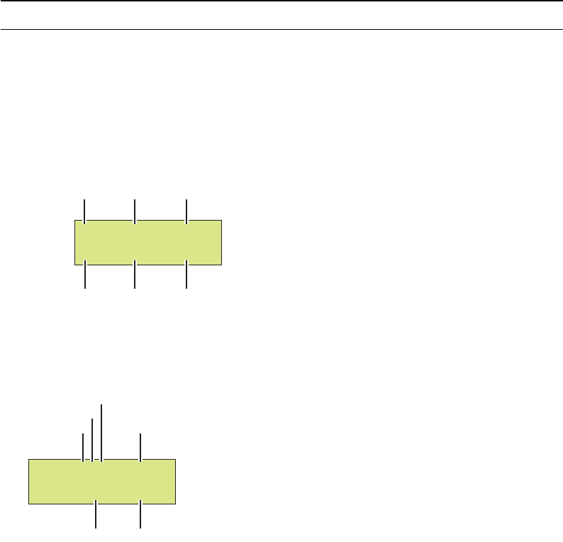
Physical controls
The physical controls on the generator consists of the Format knob, Image knob, and eight
keys, arranged into four function groups: Image, Video Gate, Sync Gate, and Outputs. All
of the keys have built-in indicator lights. When illuminated, a key’s function is considered
on, or enabled.
Power switch
This rocker switch turns the power on and off. The power supply is auto switching and can
handle 110 or 220v.
Format knob
The Format knob is used to select a video signal format from a list of stored formats. A
format is a set of parameters that specifies the video and sync signal requirements of a
particular timing. Format parameters include timing, sync type, video type, display size,
and others. By turning the knob, you can scroll through a list of formats stored in
non-volatile memory. The list includes the factory default formats. The knob list can be
edited to add custom formats. If a format containing erroneous information is selected, the
generator turns off the outputs, and displays an error message.
802BT/802R Video Test Generator User Guide 5
Image knob
The Image knob is used to select a test image from a list of stored images. The exact
behavior of the knob depends upon the status of the Image key. Turning the knob when
the light on the Image key is extinguished scrolls through the main list of test images.
Not all images are supported by all signal formats. Some images in the main image list
may be skipped while certain formats are selected. For example, the ColorBar image will
be skipped whenever a monochrome format is selected.If the currently selected image
cannot be drawn given a newly selected format, the Outline image is automatically drawn
after the new format has finished loading.
Some of the image names in the main list may refer to a sub-set of two or more different
images. The images in the sub-sets are selected by first selecting the name of the desired
sub-set from the main image list. If the sub-set consists of just two images, pressing the
Image key will toggle between the two images. The key is illuminated when the second
image is showing.
Image Step key
The Image Step key determines the behavior of the Image knob in normal operating mode
where it is used to select alternate versions of a given test image. The Step key will
illuminate only when you have selected an image with multiple versions. The following
procedure describes how to select image versions.
To select image versions:
1. Using the Image knob, select an image that has multiple versions.
2. Press the Step key. The key illuminates.
3. Turn the Image knob to step through the image versions. As you turn the knob, the
image name on the LCD will not change.
4. Press the Step key again. The light on the key extinguishes, and the Image knob
returns to normal operation.

6 Chapter 1 Getting Started
R, G, B Video Gate keys
The Video Gate keys activate (turn on) or deactivate (turn off) individual color elements
when the generator is in normal operating mode. They also control the addition of primary
color information to the NTSC / PAL video outputs on the generator. The following table
shows the function of the Video Gate keys, and commands for controlling the key function.
The master Outputs key overrides the settings of these keys when turned off.
ACS, DCS, and DSS Sync Gate keys
The Sync Gate keys are used to activate (turn on) or deactivate (turn off) sync signals
when the generator is in normal operating mode. With some formats, more than one type
of sync can be selected by pressing two keys together.
The generator selects a default sync type whenever you select a new format. Not all sync
types are available with all formats. For example, digital video formats will not allow analog
composite sync to be selected. If a key will not illuminate when pressed, then the
corresponding sync type is unavailable. Repeatedly pressing a sync gate key causes the
selected sync to be toggled on and off. When toggled off, no sync will be sent to the
display.
The master Outputs key overrides the settings of these keys when turned off.
Key Function Command
RTurns all of the red video outputs on and off.
REDG
GTurns all of the green video outputs on and off.
When a 2-bit digital monochrome (MDA) signal is
being generated, the G key turns the I (intensity)
signal of the video pair on and off.
GRNG
BTurns all of the blue video outputs on and off.
When a 1 or 2- bit digital monochrome signal is
being generated, the B key turns the V (video) sig-
nal on and off.
BLUG
Key Function Command
ACS Outputs analog composite sync on one or more of
the analog video outputs.
SSST 3; ALLU
DCS Outputs digital composite sync signal.
SSST 2; ALLU
DSS Outputs separate digital horizontal and vertical
sync signals.
SSST 1; ALLU
802BT/802R Video Test Generator User Guide 7
Outputs Key
The Outputs key turns all signal outputs on or off when the generator is in normal
operating mode. This is the master output signal control. When the master output control
is turned off, all of the signal outputs (video and sync) of the generator are disabled.
LCD
The generator displays format and image information on the LCD in either of these modes:
•Default display mode: This mode displays an index sequence number left of the
current format and current image. The image version number, which appears on the
display,represents a version of a image that has multiple versions associated with it.
•Status Display mode: This mode replaces the index numbers with codes, which
provide additional information about the active format. This mode is useful when
working with multiple video signal outputs and color encoding methods.
Video types:
• A for analog video
• D for DVI video
• H for HDMI video
Color depths:
• 4 for 4-bits per pixel depth
• 8 for 8-bits per pixel depth
Color space:
Key Function Command
ON Toggles on and off all video and sync.
OUTG
H32 150=DMT0660
V60 250=SMPTE133
Format index Format name
Image name
Image index
Horizontal rate
Vertical rate
H31 D8C=DMT0659
V60 0=SMPTE133
Video type Format name
Image name
Color depth
Color space
Image version

8 Chapter 1 Getting Started
• M for monochrome video
• C for RGB color video
• Y for YPrPb (analog) or YCrCb (digital) with 4:4:4 color sampling
• y for YCrCb (digital) with 4:2:2 color sampling
To use Status Display mode:
1. Turn off the generator.
2. Hold down the Step, G, and B keys while starting the generator, until status display
displays.
Alternatively, you can set the status display mode by entering the following command:
SROP 8; ALLU
Determining if the active format has been modified
If the active format has not been modified from the factory setting, then the index number
and format name are separated by an equal (=) character. If the active format has been
modified, then the index number and format name are separated by a blank space. The
blank space indicates that the active format has been modified from the default format
definition.
Special: keys
Status display

802BT/802R Video Test Generator User Guide 9
Video interfaces
This section describes the video interfaces available on the generator.
VGA interface
Use to output analog video for testing analog video displays. The following table describes
the VGA connector pinouts.
DVI-I interface
Use to output digital video for testing DVI-compliant video displays. Note that the DVI-I
connector also provides an analog output which can be used to test analog formats with a
VGA to DVI adapter when the generator is in analog friendly mode.
The DVI connector pinouts are shown in the following table.
Pi Signal Pin Signal Pin Signal
1 Analog Red Video 6 Analog Red Video Ground 11 No Connection
2 Analog Green Video 7 Analog Green Video Ground 12 DDC/EDID Serial Data
3 Analog Blue Video 8 Analog Blue Video Ground 13 Horizontal Sync
4 No Connection 9 DDC/EDID +5 Vdc Out 14 Vertical Sync
5 Digital Ground 10 Digital Ground 15 DDC/EDID Data Clock
Pin Signal Pin Signal Pin Signal Pin Signal
1 TMDS D2- 9 TMDS D1- 17 TMDS D0- C1 Analog Red
2 TMDS D2+ 10 TMDS D1+ 18 TMDS D0+ C2 Analog Green
3 D2/4 Shield 11 D1/3 Shield 19 D0/5 Shield C3 Analog Blue
4 TMDS D4- 12 TMDS D3- 20 TMDS D5- C4 Horizontal Sync
5 TMDS D4+ 13 TMDS D3+ 21 TMDS D5+ C5 Analog Ground
6 DDC Clock 14 +5 Vdc 22 Clock Shield
7 DDC Data 15 Ground 23 TMDS Clock+
8 No Connection 16 Hot Plug Detect 24 TMDS Clock-

10 Chapter 1 Getting Started
LVDS interface
The LVDS connector is located on the front of the generator and is labeled “Digital.” It
emulates a digital host video source and is used for testing LVDS-compliant video
displays. The LVDS connector pinouts are shown in the following table.
HDMI interface
The HDMI connector is located on the front of the generator and is labeled “HDMI.” It
emulates an HDMI-compliant video display. The HDMI connector pinouts are shown in the
following table.
HDMI Type A Connector Pinouts (HDMI option only)
Special Sync (S/S) interface
Use the S/S connector to output frame sync, line sync, composite sync, or a special probe
pulse. For more information, see Chapter 12, “Using Special Sync Output.”
S-Video interface
If you have chosen the TV option your generator will have an S-Video connector on the
right side labeled “SVIDEO.” This is a miniDIN connector that emulates an S-Video
compliant source for outputting composite TV signal.
Pin Signal Pin Signal Pin Signal Pin Signal
1 A0M 10 DDC Clock 19 A0P 28 DDC Data
2 A1M 11 DDC +5 Vdc 20 A1P 29 USB Ground
3 A2M 12 USB+ 21 A2P 30 USB-
4 Clock 1M 13 USB +5 Vdc 22 Clock 1P 31 Shield Ground
5 A3M 14 A4M 23 A3P 32 A4P
6 Shield 15 A5M 24 No Connection 33 A5P
7 No Connection 16 A6M 25 No Connection 34 A6P
8 No Connection 17 A7M 26 No Connection 35 A7P
9 No Connection 18 Clock 2M 27 DDC Ground 36 Clock 2P
Pin Signal Pin Signal Pin Signal
1 TMDS Data 2+ 7 TMDS Data0+ 13 CEC
2 TMDS Data2 Shield 8 TMDS Data0 Shield 14 Reserved (N.C.)
3 TMDS Data2- 9 TMDS Data0- 15 SCL
4 TMDS Data1+ 10 TMDS Clock+ 16 SDA
5 TMDS Data1 Shield 11 TMDS Clock Shield 17 DDC/SEC Ground
6 TMDS Data1- 12 TMDS Clock- 18 +5 V Power
802BT/802R Video Test Generator User Guide 11
Composite video BNC
If your generator is equipped with the TV option, it will have a composite TV BNC
connector on the right side, labeled “TV.” This interface emulates an analog composite TV
source.
Component video BNC interface
Your generator can be optionally equipped with separate R. G, B, HS/CS, and VS BNC
connectors on the right side. These interfaces emulate component a analog video source.

12 Chapter 1 Getting Started
Computer interfaces
This section describes the RS-232, GPIB, and USB interfaces.
RS-232 interface
Each generator has a standard RS-232 serial connector, labeled “Serial.” This is a 9-pin
D-Sub male connector which enables you to connect the generator with a computer. A null
modem cable is provided to support this interface. You can communicate with the
generator either through the command line interface from a telnet session or from the
Video Generator Manager (VGM) application. The pinouts for the RS-232 connector are
shown in the following table.
GPIB interface (optional)
The GBIP interface allows you to use the generator as a programmable video signal
source in a larger automated test system. Generators that have the GPIB interface option
have two rotary switches for setting the GPIB address. These switches are accessible
through the ventilation slots. The GPIB connector pinouts are listed in the following table.
USB interface
Use the USB interface for downloading bitmap images from a computer. With VGM 4.0 or
later, the USB interface can be used in place of the serial interface.
Pin Signal Pin Signal Pin Signal
1 Data Carrier Detect 4 Data Terminal Ready 7 Request to Send
2 Received Data 5 Signal Ground 8 Clear to Send
3 Transmitted Data 6 Data Set Ready 9 Ring Indicator
Pin Signal Pin Signal Pin Signal Pin Signal
1 DIO1 7 NRFD 13 DIO5 19 Shield
2 DIO2 8 NDAC 14 DIO6 20 Shield
3 DIO3 9 IFC 15 DIO7 21 Shield
4 DIO4 10 SRQ 16 DIO8 22 Shield
5 EOI 11 ATN 17 REN 23 Shield
6 DAV 12 Shield 18 Shield 24 Signal Ground
802BT/802R Video Test Generator User Guide 13
PCMCIA interface
Use the PCMCIA card slot to back up your custom configurations, transfer configurations
and settings from one generator to another, and store bitmap images.
14 Chapter 1 Getting Started
Command interfaces
The common test applications can be accomplished through the physical controls or
through the command line interface. The generator supports an ASCII command and
query language that allows you to control the generator interactively or through batch
processing of command files. All generator functions are supported through this interface.
The command interface is available through two physical interfaces: the RS-232 interface
and the optional IEEE-488 GPIB interface.
The GPIB interface supports programmatic control in an automated test environment,
which is discussed in more detail in Chapter 7, “Using GPIB Interface.” This interface also
supports user interactive command sessions.
The procedures for using the RS-232 interface are explained in this section.
Setting up a terminal connection with the generator
The following procedures describe how to setup a terminal session with the generator
using the RS-232 interface.
To setup a terminal connection with the generator:
Whenever the generator is powered on, the baud rate returns to 2400 bps, no parity, 8
data bits, 1 stop bit, and no handshake.
1. Connect the RS-232 cable between your computer or terminal and the serial connector
on the generator.
2. Using a terminal emulator, such as HyperTerminal, establish a terminal connection with
the generator. Configure the terminal emulator to use the following parameters:
• 2400 baud rate
• 8 data bits
• 1 stop bit
• no parity
• no handshaking
• full duplex
3. Press the Enter key until the R:> prompt appears.
802BT/802R Video Test Generator User Guide 15
Changing the baud rate
The RS-232 interface can be configured from the physical controls to support faster baud
rates and to supprort a remote keypad (optional accessory). The default configuration is
2400 baud. When the generator is powered on, the baud rate returns to the default
configuration.
To support file transfers, you can change the baud rate of the port to 38400 bps using the
command line interface or 9600 bps using the physical controls.
To increase the baud rate using the command line interface:
1. At the R:> prompt, enter the following command:
MODE 38400 n, 8, 1, h, n
After you press Enter, the terminal emulator will lose its connection with the generator,
which is now set at a different baud rate.
2. Close the terminal emulator session, change the baud rate to 38400, and then re-open
the session, specifying the baud rate as 38400.
To change the baud rate to 9600 using the front panel:
1. Turn off the generator.
2. Hold down the R and DCS keys while starting the generator. The serial port is now set
to 9600 bps. Restarting the generator again, without pressing any keys, will
Sending commands interactively
This procedure describes how to send commands through an interactive user session.
The generator parses command lines one at a time. Command lines must be terminated
with a carriage return (<cr>). The generator immediately echoes each character as it is
received and places it in a command line buffer. When sending multiple commands at
once, separate each command with a semi-colon. Commands are not case sensitive.
To send single commands to the generator:
1. Establish a terminal session with the generator (see page 14).
2. At the R:> prompt, enter commands or queries and terminate with a carriage return.
Command examples
• To display the name of the format currently in the format buffer, enter:
FMTL?
• To load a format, enter:
FMTL format_name
16 Chapter 1 Getting Started
• To apply the format to the generator hardware, enter:
FMTU
• To load an image, enter:
IMGL image_name
• To apply the image to the generator hardware, enter:
IMGU
To send multiple queries and commands to the generator:
1. Establish a terminal session with the generator (see page 14).
2. At the R:> prompt, enter the queries or commands, separating each with a semi-colon
and terminating the command line with a carriage return.
Command examples:
• To query the current format and then load a new format enter the following:
FMTL?; FMTL new_format; FMTL? FMTU
The generator will return the following in response to this command and query string:
current_format; new_format
• To change the format and image active in the generator enter:
FMTL 480p59; IMGL SMPTEbar; ALLU
This tells the generator to load the 480p59 format named “” into the format data buffer,
the image named “SMPTEbar” into the image data buffer, and then to “use” the
contents of both (“all”) buffers to drive the generator's output.
Sending commands from text files
When developing more complex, custom test sequences or formats, it is easiest to enter
commands in a text file, and then send the file to the generator. This approach allows you
to modify the file without entering the entire command script.
To send a text file to the generator:
1. Using a text editor, enter the commands that define a test sequence or format into a
text file, and save the text file using a *.txt extension.
2. Establish a terminal session with the generator (see page 14).
802BT/802R Video Test Generator User Guide 17
3. At the R:> prompt, transfer the text file to the generator. For example, to transfer a file
using HyperTerminal, do the following:
a. On the Transfer menu, click Send Text File. The Send Text File dialog box
appears.
b. Select the text file you want to send, and then click Open. HyperTerminal displays
the commands as they are sent.
c. Press Enter once to ensure that the last command is sent.
18 Chapter 1 Getting Started
Special operating modes
You can set the generator to operate in various modes to accomplish specific functions.
When any special operational mode is set, it persists (until overridden) throughout
subsequent power cycles, which may be performed to set other modes.
You can view the operational settings and special functions of the generator on a video
display by viewing the GenOps image. This image provides key sequences and the status
of special operating modes in the generator.
To determine the status of operating modes:
1. Connect the appropriate interface cable to the video display.
2. Using the Format knob, select a format suitable for the display.
3. Turn the Image knob to select the GenOps image.

802BT/802R Video Test Generator User Guide 19
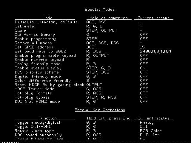
Summary of special modes
The following table describes the special operating modes, and how to configure the
modes using the physical controls or the command line interface.
Special mode Function Physical control Command
Initialize with factory
defaults Re-initializes generator to fac-
tory defaults. Removes all spe-
cial modes, deletes all custom
objects.
ACS, DSS
INIT
Calibrate Calibrates the generator. R, G, B
SCAL
SROP 32
Clone Copies configuration settings
from one generator to other
generators using a PCMCIA
card.
Step, Outputs Set: SROP 64
Rst: SROP 0 64
Old format library Displays old format names on
LCD.
G Set: SROP 1
Rst: SROP 0 1
Remove all modes Removes all special modes. ACS, DCS, DSS Set: SROP 0
Set GPIB address Sets the GPIB address. DCS Set: GPIB
addr
Rst: INIT
Set baud rate to 9600 Sets baud rate of RS-232 port
to 9600 bps.
R, DCS Set: SROP 256
Rst: SROP 0 256
Enable programmable
keypad
R, OUTPUT Set: SROP 512
Rst: SROP 0 512
Enable numeric key-
pad
Enables remote operation
through remote keypad.
R Set: SROP 128
Rst: SROP 0 128
Analog friendly mode Causes all digital formats to
output analog video signal.
R, B Set: SROP 4
Rst: SROP 0 4
Enable status display Provides additional information
on LCD (analog/digital and
color depth).
Step, G, B Set: SROP 8
Rst: SROP 0 8
DCS priority scheme Changes priority scheme for
putting CS on separate VS and
HS sync outputs when any dig-
ital composite sync (DCS) type
is selected
Step, DCS Set: SROP 4096
Rst: SROP 0 4096
Digital friendly mode Causes all analog formats out-
put digital signal
G, B Set: SROP 2
Rst: SROP 0 2
Color difference
friendly
Outputs digital YCbCr for tele-
vision formats.
B Set: SROP 2048
Rst: SROP 0 2048
Reset HDCP Rx gating
clock
Resets the receiver, and gates
off transmitter clock and data.
Outputs Set: SROP 16
Rst: SROP 0 16

20 Chapter 1 Getting Started
Special key operations summary
The following table describes modes that can be enabled while the generator is running,
and the physical controls and comands for using the modes.
HDCP tester mode Enables HDCP testing. G, ACS Set: SROP 8192
Rst: SROP 0 8192
Hot plug formats Auto-configures generator for-
mat knob list based on EDID in
response to hot plug.
R, ACS Set: SROP 16384
Rst: SROP 0 16384
DVI mode (disable
HDMI)
Outputs DVI on HDMI connec-
tor.
R, G Set: SROP 32768
Rst: SROP 0 32768
Hot plug bypass Bypasses hot plug detection
and auto-configuration of the
generator.
Step, R, ACS Set: SROP 65536
Rst: SROP 0 65536
Special mode Function Physical control Command
Mode Function
Physical control
(hold 1st & press
2nd) Command
Toggle analog/digital Outputs either digital or ana-
log.
G, B AVST x; DVST x
Rotate video type Outputs either RGB, color dif-
ference, or monochrome.
R, B
DDC-based auto-con-
figuration
Auto-configures generator for-
mat knob list based on EDID.
R, ACS
Toggle biLevel/triLevel Toggles between tri-level and
bi-level syncs for analog HDTV
formats with tri-level sync type.
B, ACS TSPG x
802BT/802R Video Test Generator User Guide 21
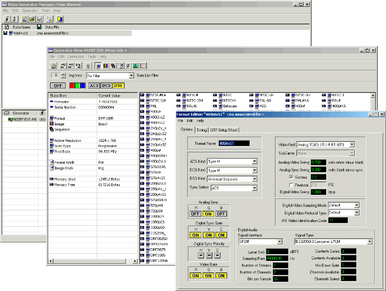
About Video Generator Manager
Video Generator Manager (VGM) is a Microsoft Windows-based program used to operate
the generator from a computer.
VGM features
VGM supports the following functions.
• Creating custom test sequences.
• Creating customized Image or Format knob lists.
• Creating custom formats or modifying existing formats.
• Creating custom images or modifying existing images.
• Archiving custom data.
• Upgrading the generator firmware.
• Re-initializing a generator.
• Calibrating a generator.
• Downloading a bitmap image to a generator.
22 Chapter 1 Getting Started
For information about using VGM, see the VGM online help.
Installing VGM
VGM is available on the Resource CD included with the generator, and from
http://www.quantumdata.com/support/downloads/.
To install VGM:
1. Log onto Windows with Administrator privileges.
2. Do one of the following:
• On the Resource CD, double-click the setup.exe file to begin the installation.
• On the Quantum Data Web site, click the setup.exe file to begin the installation.
3. Follow the on-screen instructions.
802BT/802R Video Test Generator User Guide 23
2Testing Video Displays
Topics in this chapter:
•General video display testing procedure
•Testing analog computer (IT) CRTs
•Testing digital computer (IT) FPDs
•Testing analog composite video SDTV (CE) CRTs
•Testing analog component video SDTV (CE) CRTs
•Testing digital component video HDTV (CE) flat panel displays

24 Chapter 2 Testing Video Displays
General video display testing procedure
This section provides an overview of the video testing process, which involves connecting
the generator to the display under test, selecting a format appropriate for the display, and
then selecting images to exercise the display to ensure proper functioning.
Making physical connections
Use the following table to connect the generator with display under test.
Setting the video output mode
If the application involves testing similar displays with one type of video signal output for
extended periods of time (for example, in a production environment), use one of the
following modes:
•Digital Friendly mode – Digital formats are output without change, while analog
formats are temporarily switched to digital. This mode is available only if the generator
has a digital option (DVI, LVDS, or HDMI) installed.
•Analog Friendly mode – Analog formats are output without change, while the digital
formats are temporarily switched to analog.
For information about using these modes, see “Summary of special modes” on page 19.
When you need to test various video signal outputs and color encoding methods (for
example, in a repair center), disable all friendly modes, and enable the Status Display
mode (see “LCD” on page 7) so that you can determine the current configuration. Then,
Display type Signal type Cable
Information
Technology
(IT)
Computer - VESA (DMT,
CVT)
Analog component RGB VGA to VGA
Computer - VESA DDWG Digital component RGB DVI to DVI
Consumer
Equipment
(CE)
SDTV - ITU-470-6 base-
band
Analog composite CVBS BNC to RCA 75 Ohm
SDTV - ITU-470-6 base-
band
Analog composite S-Video S-Video (miniDin to
MiniDin)
SDTV - CEA-861B Analog component YPbPr VGA to RCA1
1. Optional cable available from Quantum Data.
HDTV - CEA-861B Digital component DVI
RGB
DVI to DVI, or HDMI to
DVI
HDTV - CEA-861B Digital component HDMI
RGB and YCbCr
HDMI to HDMI

802BT/802R Video Test Generator User Guide 25
hold down the G key while pressing and releasing the B key to switch between digital and
analog outputs. The table below shows the AVST and DVST command settings for analog
and digital outputs.
Selecting video formats
This section explains how to configure the generator to output video formats that are
supported by the device being tested.
Note: You can create your own formats. See “Creating custom formats” on page 63 for
details. Additionally, you can create your own Format knob lists. See “Editing Format knob
lists” on page 67 for details.
Selecting formats automatically
When testing EDID-compatible displays, the generator can automatically update the
Format knob list (list of format names shown on the LCD) to include only formats
supported by the display under test. Depending on the output used, the generator can do
this on demand, or automatically when a display is connected.
To update the Format knob list on demand:
1. Connect the display you want to test with the generator.
2. Hold down the R key, and then press and release the ACS key. This puts the generator
into either Analog Friendly or Digital Friendly mode based on the EDID that the
generator receives.
3. Turn the Format knob to choose a format. Only formats supported by the display are
listed.
Video Signal Interface AVST DVST
Analog YYY Grayscale 1 0
Analog RGB Color 2 0
CVBS or S-Video Grayscale 3 0
CVBS or S-Video Color 4 0
Analog YPbPr SDTV Color 6 0
Analog YPbPr HDTV Color 7 0
Digital YYY Grayscale 0 9
Digital RGB Color 0 10
Digital YCbCr SDTVColor 0 13
Digital YCbCr HDTV Color 0 14
26 Chapter 2 Testing Video Displays
To update the Format knob list automatically when a display is connected:
1. Connect the display you want to test with the DVI or HDMI connector on the generator.
(Analog outputs do not support this feature.)
2. Turn the generator off.
3. Hold down the R and ACS keys while starting the generator, until hot plug formats
displays on the LCD.
Note: The generator is now in Digital Friendly mode.
4. Turn the Format knob to choose a format. Only formats supported by the display are
listed.
5. Connect a different device to automatically update the Format knob list again.
Selecting formats manually
When testing a display that is not EDID-compliant, you must manually choose formats
from the generator that are supported by the display.
To do this:
• Identifing the type of display (composite television, component standard definition
television, component high definition television, computer equipment, or other specialty
display).
• Check the specifications of your display for supported formats.
• Learn how the format library is organized, and how formats are named (see below).
• Turn the Format knob to try formats from the appropriate format category. Try the
DMT0660 (VGA) format if you are not sure of which formats to use.
Understanding the format library
After connecting the generator with the display under test, turn generator on, and select a
video format.
This section describes how to choose a video format, from the list of formats built into the
generator, for the display you are testing. A format defines a set of video, timing and sync
parameters for a specific device or standard.
A summary of the format naming convention is provided. For a detailed description of the
naming conventions, see to “Format naming conventions” on page 56.
Organization of format library
The generator has several built-in formats to test a broad range of display types. These
formats are grouped in the following categories:
802BT/802R Video Test Generator User Guide 27
• Composite television formats
• Component standard definition television formats
• Component high definition television
• Computer display formats
• Military and medical display formats
• Miscellaneous formats
When you turn the Format knob, the formats are listed in the order shown above.
Composite television formats
Composite television formats are named by the standards defining them. The first three to
five characters of the format name indicate the color coding scheme. The first set of
characters refers to the standard. The next characters are optional and indicate
adjustments to the format. Examples of these formats are:
• NTSC (North American TV)
• PAL (European TV)
• NTSC-J - (where J refers to a Japan standard per NTSC without 7.5 IRE setup)
• PAL-N (where N indicates 3.58205625 MHz color sub-carrier)
• PAL# (where # indicates that the sampling rate is reduced to achieve square pixels)
Component standard definition television formats
Component SDTV formats are applicable in the case of RGB, YPbPr. These formats are
named by their vertical resolution, scanning method, and frame rate. The initial characters
indicating the resolution are followed by the scanning method. The two characters
following the scanning method indicate the frame rate. A typical example of component
standard or definition TV video format is:
• 480i2x30 (for a vertical resolution of 480 pixels with interlaced scanning and a 30 Hz
frame refresh rate; 2x indicates that the pixels are double-clocked for DVI compatibility).
Component high definition television formats
Component high definition television formats, like the standard definition television
formats, are named by their vertical resolution, scanning method, and frame rate. These
formats are applicable in the case of RGB, YPbPr, and YCbCr. These initial characters
indicating the resolution are followed by the scanning method. The two characters
following the scanning method indicate the frame rate. A typical example of component
high definition TV video format is:
• 1080i30 (for a vertical resolution of 1080 active vertical lines with interlaced scanning
and a 30 Hz frame refresh rate).
28 Chapter 2 Testing Video Displays
Computer display formats
Computer display formats are assumed to use progressive scanning. Computer format
names consist of four blocks. The initial three characters indicate the vendor ID using the
EISA ID (for example, IBM, SUN, and VSC) or the standard body or acronym (for example,
SMT, DMT, GTF, CEA, and EIA). The next two characters provide the first two digits of the
horizontal resolution in pixels. Following the horizontal resolution are two characters which
indicate the frame rate. The final character indicates the aperture, which is used only if the
aperture is not 1.33 (A). The following are examples of computer display formats:
• VSC1275 for Viewsonic 1280 by 1024 at 75 Hz
• DMT0685 for Discrete Monitor Timing with 680 by 480 at 85 Hz
Viewing format parameters
You can use the Format image or VGM to view detailed information about formats in the
generator.
To view formats parameters using VGM:
• Open each format in the Font Editor.
• Generate a detailed format listing.
Refer to the VGM online help for instructions.
Selecting images
Once you have determined the format or formats appropriate for testing the display you
will apply a series of images suitable for evaluating the display. Of primary importance is
determining what type of display you are testing (for example, CRT or digital flat panel
display). You must also determine if you are testing composite TV and use images
appropriate for these formats and video types.
Each image in the generator’s library is intended to test one or more attributes of a
particular display type and video type.
Note: You can create your own images. See “Creating custom images” on page 75 for
details. Additionally, you can create your own custom Image knob lists. See “Editing Image
knob list” on page 81 for details.

802BT/802R Video Test Generator User Guide 29
The table below provides a summary of display characteristics and the images used to
evaluate them. For details on the images and display attributes, see Appendix B, “Image
Reference.”
Display type Display test Recommended images
Analog CRT Geometry (pin and barrel,
linearity)
Static images
Hatch (TVHatch, Hatch_16, Hatch_20), Cir-
clesL, Geom_1 - Geom_5, SMPTE133
Focus Focus_@6, Focus_@7, Focus_@8,
Focus_@9, Text_9, Text_9T, Text_11,
Text_12T, Text_16
Photometry (chrominance,
contrast, levels)
Flat, Flat07, Flat13, Flat20, Flat27, Flat33,
Flat40, Flat47, Flat53, Flat60, Flat67, Flat73,
Flat80, Flat87, Flat93, FlatGray, Flat_01,
Flat_02, Flat_03, Flat_04, Flat_05, Flat_06,
Flat_07, Flat_08, Flat_09, Flat_10, Flat_11,
Flat_12, Flat_13, Flat_14, Flat_15, Flat_16,
Ramp_B, Ramp_G, and Ramp_R,
ColorBar, SMPTEbar, TVBar100 & TVBar_75
(TV formats only)
Luminance SMPTE133 (grayscale), Grays5, Grays9,
Grays11, Grays16, Grays32, Grays64
Gamma correction SMPTE133 (checkerbox)
Resolution BurstTCE, Burst (TV formats only), Grill_11,
Grill_15, Grill_22, Grill_33, Grill_44
Pulse (CE SDTV) PulseBar
Centering Outline0, Outline1, Outline2, Outline3
Voltage Regulation Regulate
Electromagnetic Interfer-
ence
EMITest1, EMITest2, EMITest3, EMITest4,
EMITest5

30 Chapter 2 Testing Video Displays
Digital flat panel
(fixed pixel dis-
play)
Pixel anomalies (stuck pix-
els, misc sampling)
Flat, Raster, Ramp_B, Ramp_G, and Ramp_R,
Focus_@6, Focus_@7, Focus_@8,
Focus_@9, Text_9, Text_9T, Text_11,
Text_12T, Text_16
Photometry (chrominance,
contrast, levels)
Flat, Flat07, Flat13, Flat20, Flat27, Flat33,
Flat40, Flat47, Flat53, Flat60, Flat67, Flat73,
Flat80, Flat87, Flat93, FlatGray, Flat_01,
Flat_02, Flat_03, Flat_04, Flat_05, Flat_06,
Flat_07, Flat_08, Flat_09, Flat_10, Flat_11,
Flat_12, Flat_13, Flat_14, Flat_15, Flat_16,
Ramp_B, Ramp_G, and Ramp_R, ColorBar,
SMPTEbar, SMPTE133
Luminance SMPTE133 (grayscale), Grays5, Grays9,
Grays11, Grays16, Grays32, Grays64
Centering Outline0, Outline1, Outline2, Outline3
Resolution BurstTCE, Grill_11, Grill_15, Grill_22, Grill_33,
Grill_44
Persistence Animated images: Persist, Cubes, SlideX
Display type Display test Recommended images

802BT/802R Video Test Generator User Guide 31
Testing analog computer (IT) CRTs
This section describes how to test analog computer (IT) displays.
To test an analog computer CRT:
1. Use a standard VGA cable to connect the VGA connector on the generator with the
VGA connector on the display under test.
2. Calibrate the generator by holding down the R, G and B keys while starting the
generator. See “Calibrating the generator” on page 47.
You can also calibrate the generator by entering the following command:
SCAL
When calibrating the generator, if you load the analog outputs (as they will be loaded
when conducting testing) then the calibrations will be slightly more accurate. This is not
required however. Also, loading the unused outputs with 75 ohms will optimize signal
damping.
3. (Optional) Enable the Status Display mode and Analog Friendly mode (see “Special
operating modes” on page 18). The Analog Friendly mode ensures that the generator
will output an analog signal. The Status Display mode enables you to view the current
output characteristics on the LCD.
4. Determine the formats to test (see “Selecting formats automatically” on page 25).
5. (Optional) To view the EDID on the display, use the Image knob to select the EdidData
image and follow the directions on the display. You may wish to view the EDID data to
verify that the formats required for testing are specified in the EDID.
Alternatively, you can load the image with the following command:
IMGL EdidData; IMGU
6. Determine additional formats to test based on the resolution of the display. The VESA
formats are shown below:
Standard Quantum Data format name
VGA DMT06xx
SVGA DMT08xx
XGA DMT10xx
SXGA DMT12xx
UXGA DMT16xx
QXGA DMT20xx
QSXBA DMT25xx
32 Chapter 2 Testing Video Displays
Determine the images to test:
For analog CRTs you typically want to select images to test for geometry, focusing,
photometry, resolution, cross talk, EMI, and regulation characteristics. For more details on
what images test these specific display attributes, see “Selecting images” on page 28 or
Appendix B, “Image Reference.”
Verify the test set-up:
1. Using the Format knob, select one of the formats you have identified.
Alternatively, you can load the format with the following command:
FMTL format_name; FMTU
2. Using the Image knob, select a suitable image such as ColorBar. Verify that the display
is presenting the image to ensure that the generator is sending a valid signal to the
display.
Alternatively, you can load the image with the following command:
IMGL ColorBar; IMGU
Test the display:
1. Using the Format knob, select the first test format identified.
Alternatively, use these commands to load the format:
FMTL format_name; FMTU
2. Using the Image knob, select the first test image.
Alternatively, you can also load an image with the following command:
IMGL image_name; IMGU
3. Repeat steps 1 and 2 for all formats and test images. Use the following guidelines to
verify proper operation:
• When testing geometry with the Hatch images (for example, Hatch20) look for
distortion with concave or convex lines near the periphery of the display. Look for
irregular spacing on the cross hatch patterns.
• When testing photometry such as chrominance, use the ColorBar, SMPTE133, or
SMPTEbar images. Look for missing bars which may indicate a dead or
unconnected channel. Also, look at the transition between the bars; they should be
sharp and distinct. Each bar also should be uniform in color and intensity across its
entire width.
• To test luminance, you can use the SMPTE133 (grayscale portion) image. To test
gamma correction, you can use the SMPTE133 (checkerbox portion) image. The
detailed methods for verifying these parameters on the SMPTE133 image are
provided in Appendix B, “Image Reference.”
• When testing focus with the Focus or Text images, the characters in all areas of the
display should be well-formed and in focus.
802BT/802R Video Test Generator User Guide 33
• When testing resolution with the Grill images, you should be able to see individual
and distinct stripes in all areas of the display at all four resolutions.
• When testing for centering use the Outline images. For detailed methods for
verifying centering with the Outline images, see Appendix B, “Image Reference.”
• When testing for high voltage regulation with the Regulate image, observe the
outline at the edges of the image. They should stay in place and not pull away from
the area of the large white blinking patch (when it appears).
Note: You can customize your generator to run through a specified set of formats and
images automatically or manually by creating test sequences. See to “Creating a test
sequence” on page 87 for details.
34 Chapter 2 Testing Video Displays
Testing digital computer (IT) FPDs
This section describes how to test digital computer (IT) displays.
To test a digital FPD:
1. Use a DVI-I cable to connect the DVI output on the generator with the DVI connector on
the display under test.
2. Place the generator in Digital Friendly mode by holding down the G and B keys while
starting the generator.
Alternatively, you can set the Digital Friendly mode by entering the following command:
SROP 2 4; ALLU
The Digital Friendly mode ensures that the generator will output a digital signal on the
DVI connector, when selecting analog formats from the format library.
3. Determine the formats to test. Auto-select the formats to test by enabling the
generator’s DDC-based auto configuration. See “Selecting formats automatically” on
page 25 for instructions.
4. (Optional) To view the EDID on the display, use the Image knob to select the EdidData
image and follow the directions on the display. Verify that the EDID specifies the formats
required for testing.
Alternatively, you can load the image with the following command:
IMGL EdidData; IMGU
5. Determine which images to test. For digital flat panel displays, you typically want to
select images to test for pixel anomalies, persistence, photometry and resolution
related problems. For more information, see “Selecting images” on page 28 or
Appendix B, “Image Reference.”
Verify the test set-up:
1. Using the Format knob, select one of the formats you have identified.
Alternatively, you can load the format with the following command:
FMTL format_name; FMTU
2. Using the Image knob, select a suitable image such as SMPTE133. Verify that the
display is presenting the image to ensure that the generator is sending a valid signal to
the display.
Alternatively, you can load the image with the following command:
IMGL SMPTE133; IMGU
Test the display:
1. Using the Format knob, select the first test format identified.
802BT/802R Video Test Generator User Guide 35
2. Using the Image knob, select the first test image.
3. Repeat steps 1 and 2 for all formats and test images. Use the following guidelines to
verify proper operation:
• When testing photometry such as chrominance, use the ColorBar, SMPTE133, or
SMPTEbar images. Look for missing bars which may indicate a dead or
unconnected channel. Also, look at the transition between the bars; they should be
sharp and distinct. Each bar also should be uniform in color and intensity across its
entire width.
• To test luminance, you can use the SMPTE133 (grayscale portion) image. To test
gamma correction, you can use the SMPTE133 (checkerbox portion) image. The
detailed methods for verifying these parameters on the SMPTE133 image are
provided in Appendix B, “Image Reference.”
• When testing for centering use the Outline images. The detailed methods for
verifying centering with the Outline images (Outline0, Outline1, Outline2, Outline3)
are provided in Appendix B, “Image Reference.”
• When testing resolution with the Grill images, you should be able to see individual
and distinct stripes in all areas of the display at all four resolutions.
• When testing for pixel anomalies use the Flat, Raster and Ramp images. Use the
Raster and Flat images to look for pixels that may be stuck On or Off, respectively.
The luminance should increase uniformly for the Ramp image. Also, look for
sparkles indicating problems with sampling.
• When testing for persistence with the animated images (for example, Cubes and
Persist), look for bleeding or trails in the wake of the moving object.
Note: You can customize your generator to run through a specified set of formats and
images automatically or manually by creating test sequences. See “Creating a test
sequence” on page 87 for details.
36 Chapter 2 Testing Video Displays
Testing analog composite video SDTV (CE) CRTs
This section describes how to test CRT composite televisions with analog composite video
inputs.
To test analog composite video SDTV:
1. Use a standard coax cable to connect the TV BNC connector on the generator with the
display under test.
Or, use an S-video cable to connect the SVIDEO connector on the generator with the
S-Video input on the display under test.
2. (Optional) Place the generator in Analog Friendly mode by holding down the R and B
keys while starting the generator (see “Special operating modes” on page 18).
The Analog Friendly mode ensures that the generator will output an analog signal.
3. Determine which composite television standard you need, such as NTSC or PAL, and
then select the formats compatible with the standard. Typically, you would test all the
formats in the family of formats for a standard.
4. Determine the images to test. For analog CRTs you typically want to select images to
test for geometry, focusing, photometry, resolution, cross talk, EMI, and regulation
characteristics. For more details on what images test these specific display attributes,
see “Selecting images” on page 28 or Appendix B, “Image Reference.”
Verify the test set-up:
1. Using the Format knob, select the first NTSC or PAL format.
Alternatively, you can load the format with the following command:
FMTL format_name; FMTU
2. Using the Image knob, select a suitable image such as SMPTEBar. Verify that the
generator is sending a valid signal to the display and that the display is presenting it.
Alternatively, you can load the image with the following command:
IMGL SMPTEBar; IMGU
Test the display:
1. Using the Format knob, select the first test format.
2. Using the Image knob, select the first test image.
Note: You can customize your generator to run through a specified set of formats and
images automatically or manually by creating test sequences. See “Creating a test
sequence” on page 87 for details.
3. Repeat steps 1 and 2 for all formats and test images. Use the following guidelines to
verify proper operation:
802BT/802R Video Test Generator User Guide 37
• When testing geometry with the Hatch images (for example, TVHatch and
Hatch20) look for distortion with concave or convex lines near the periphery of the
display. Look for irregular spacing on the cross hatch patterns.
• When testing photometry such as chrominance, use the TVBar100 & TVBar_75
(TV formats only), TVSplBar, SMPTE133 or SMPTEbar images. Look for missing
bars which may indicate a dead or unconnected channel. Also, look at the transition
between the bars; they should be sharp and distinct. Each bar also should be
uniform in color and intensity across its entire width.
• When testing focus with the Focus images, the characters in all areas of the display
should be well-formed and in focus.
• When testing resolution with the Grill images, you should be able to see individual
and distinct stripes in all areas of the display at all four resolutions. When testing
for resolution with the Burst image, the peak intensities of the all of the bursts
should match the white reference level. The darkest portions between the peaks
should match the black reference level.
• When testing for centering, use the Outline and TVoutLin images. The detailed
methods for verifying centering with the Outline images (Outline0, Outline1,
Outline2, Outline3) are provided in Appendix B, “Image Reference.”
• When testing for high voltage regulation with the Regulate image, observe the
outline at the edges of the image. They should stay in place and not pull away from
the area of the large, white blinking patch (when it appears).
38 Chapter 2 Testing Video Displays
Testing analog component video SDTV (CE) CRTs
This section describes how to test CRT televisions with standard definition component
video inputs.
To test an analog component video SDTV display:
1. Use a VGA-to-RCA cable to connect the VGA connector on the generator with the
YPbPr inputs on the display under test.
Or, if your generator has optional component BNC connectors, use a BNC to RCA
cable to connect the BNCs on the generator with the RCA connectors on the display
under test.
2. Identify the component television formats to test. These formats are listed after the
composite television formats in the generator’s default Format knob list. Begin with the
first format in the range of standard definition component television formats (480i).
3. Determine additional formats to test based on the resolution of the television display.
The television specification sheet will provide information on what resolutions to test. It
is necessary to test only those resolutions with the supported scanning type (typically,
interlaced for a standard definition television).
4. Determine the images to test. For analog CRTs you typically want to select images to
test for geometry, focusing, photometry, resolution, cross talk, EMI, and regulation
characteristics. For more details on what images test these specific display attributes,
see “Selecting images” on page 28 or Appendix B, “Image Reference.”
Verify the test set-up:
1. Using the Format knob, select the first component video format (480i).
Alternatively, you can load the format with the following command:
FMTL 480i; FMTU
2. Using the Image knob, select a suitable image such as SMPTE133. Verify that the
generator is sending a valid signal to the display and that the display is presenting it.
Alternatively, you can load the image with the following command:
IMGL SMPTE133; IMGU
Test the display:
1. Using the Format knob, select the first test format.
2. Using the Image knob, select the first test image.
Note: You can customize your generator to run through a specified set of formats and
images automatically or manually by creating test sequences. See “Creating a test
sequence” on page 87 for details.
802BT/802R Video Test Generator User Guide 39
3. Repeat steps 1 and 2 for all formats and test images. Use the following guidelines to
verify proper operation:
• When testing geometry with the Hatch images (for example, TVHatch and
Hatch20), look for distortion with concave or convex lines near the periphery of the
display. Look for irregular spacing on the cross hatch patterns.
• When testing photometry such as chrominence, use the TVBar100 & TVBar_75
(TV formats only), ColorBar, SMPTE133 or SMPTEbar images. Look for missing
bars which may indicate a dead or unconnected channel. Also, look at the transition
between the bars; they should be sharp and distinct. Each bar also should be
uniform in color and intensity across its entire width.
• To test luminance you can use the SMPTE133 (grayscale portion) image. To test
gamma correction you can use the SMPTE133 (checkerbox portion) image. The
detailed methods for verifying these parameters on the SMPTE133 image are
provided in Appendix B, “Image Reference.”
• When testing focus with the Focus or Text images, the characters in all areas of the
display should be well-formed and in focus.
• When testing resolution with the Grill images, you should be able to see individual
and distinct stripes in all areas of the display at all four resolutions.
• When testing for centering use the TVOutline and Outline images. The detailed
methods for verifying centering with the Outline images (Outline0, Outline1,
Outline2, Outline3) are provided in Appendix B, “Image Reference.”
• When testing for high voltage regulation with the Regulate image, observe the
outline at the edges of the image. They should stay in place and not pull away from
the area of the large white blinking patch (when it appears).
40 Chapter 2 Testing Video Displays
Testing digital component video HDTV (CE) flat panel
displays
This section describes how to test digital component video for HDTV flat panel displays.
To test a digital (DVI) component video HDTV display:
1. Use a standard DVI cable to the DVI connector on the generator and then to the DVI
connector on the television display under test.
Note: If the display under test has a DVI-D connector you will need a DVI-I to DVI-D
adaptor.
2. Place the generator in Digital Friendly mode by holding down the G and B keys while
starting the generator (see “Special operating modes” on page 18).
This mode ensures that the generator outputs a digital signal on the DVI connector,
even when selecting analog formats from the format library.
3. Identify the high definition component television formats to test. These formats are
listed after the composite television formats in the generator’s default Format knob list.
Begin with the first format (720p) in the range of high definition component television
formats. See “Selecting formats automatically” on page 25.
4. Determine additional formats to test based on the resolution of the television display.
The television product specification sheet will provide information on what resolutions
to test. It is necessary to test only those resolutions with the supported scanning type
(typically interlaced for a high definition television).
5. Determing which images to test. For digital television flat panel displays, you would
typically want to select images to test for pixel anomalies, persistence, photometry and
resolution related problems. For more details on which images test these specific
display attributes, see “Selecting images” on page 28 or Appendix B, “Image
Reference.”
Verify the test set up:
1. Using the Format knob, select the first HDTV video format (720p50).
Alternatively, you can load the format with the following command:
FMTL 720p50; FMTU
2. Using the Image knob, select a suitable image such as the SMPTE133 image. Verify
that the generator is sending a valid signal to the display and that the display is
presenting it.
Alternatively, you can load the image with the following command:
IMGL SMPTE133; IMGU
802BT/802R Video Test Generator User Guide 41
Test the display:
1. Using the Format knob, select the first test format.
2. Using the Image knob, select the first test image.
Note: You can customize your generator to run through a specified set of formats and
images automatically or manually by creating test sequences. See “Creating a test
sequence” on page 87 for details.
3. Repeat steps 1 and 2 for all formats and test images. Use the following guidelines to
verify proper operation:
• When testing photometry such as chrominence, use the ColorBar, SMPTE133, or
SMPTEbar images. Look for missing bars which may indicate a dead or
unconnected channel. Also, look at the transition between the bars; they should be
sharp and distinct. Each bar also should be uniform in color and intensity across its
entire width.
• To test luminance, you can use the SMPTE133 (grayscale) images. To test gamma
correction, you can use the SMPTE133 (checkerbox) image. The detailed methods
for verifying these parameters on the SMPTE133 Image are provided in Appendix
B, “Image Reference.”
• When testing for centering, use the Outline images. The detailed methods for
verifying centering with the Outline images (Outline0, Outline1, Outline2, Outline3)
are provided in Appendix B, “Image Reference.”
• When testing resolution with the Grill images, you should be able to see individual
and distinct stripes in all areas of the display at all four resolutions.
• When testing for pixel anomalies, use the Flat, Raster, and Ramp images. Use the
Raster and Flat images to look for pixels that may be stuck On or Off, respectively.
The luminance should increase uniformly for the Ramp image. Also look for
sparkles indicating problems with sampling.
• When testing for persistence with the animated images (Cubes and Persist), look
for bleeding or trails in the wake of the moving object.
42 Chapter 2 Testing Video Displays
802BT/802R Video Test Generator User Guide 43
3Administrative Tasks
The chapter describes how to accomplish common administrative tasks. Most
administrative functions are supported through the front panel or command line interface.
However, upgrading firmware can only be achieved through VGM; it is not supported
through the front panel. Most administrative functions are supported through the VGM
application. See the VGM online help for information on performing these administrative
tasks through VGM.
Topics in this chapter:
•Displaying system information
•Restoring factory settings
•Calibrating the generator
•Cloning generators
•Installing firmware
•Memory management
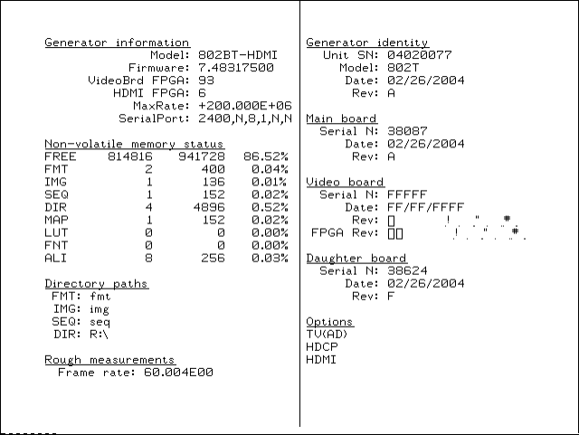
44 Chapter 3 Administrative Tasks
Displaying system information
Use the GenStats image to display information about the generator, including revision
levels of FPGA software installed. This image also list installed options.
To display information about generator:
1. Connect the generator with a display.
2. Choose a format supported by the display.
3. Turn the Image knob to select the GenStats image.
802BT/802R Video Test Generator User Guide 45
Restoring factory settings
This section describes how to set and restore the generator system parameters.
System Parameters
The following system parameters are stored in the 802’s non-volatile system memory:
• The reference rate calibration factor. The 802 uses a crystal controlled oscillator as the
reference for all timing signals. The crystal frequency has a maximum error of ±50 ppm.
The 802 hardware and firmware is capable of compensating for this small amount of
error by applying a user set calibration factor. The factory default setting is 1.000 for the
calibration factor. Use the
RATC
command to set the pixel calibration factors.
• The maximum pixel clock rate used for error checking formats. All 802 generators will
operate, to some extent, at pixel rates beyond their spec sheet limits. The maximum
rate can be set to a higher limit if it is known that a particular unit will work reliably at
the higher limit. Use the
JRAT
command to set the maximum pixel rate used for error
checking of analog formats.
• The gamma correction flag. This flag determines whether individual formats can control
the application of gamma correction or if gamma correction is disabled regardless of a
format’s setting. The factory default setting is to allow gamma correction to be
controlled by individual formats. Use the
GAMC
command to enable or disable the
gamma correction flag.
Setting and restoring system parameters
There are two ways of changing the settings of these parameters:
• They can be restored to their default factory settings as part of a user initiated system
reset. This will also restore the entire format storage memory to its factory default
contents.
• A suitably equipped computer or terminal connected to one of the communications
ports can be used to set the parameters to user defined settings.
When the generator is reinitialized, each format in the standard library is tested
(one-at-a-time), to determine if the format parameters are fully supported by the generator.
This algorithm is necessary because the standard format library is used across all
generators. If there are some limitation the generator applies a format justification
algorithm. In these cases the generator stores a modified version of the format under a
similar name. If the format is beyond what can be corrected the format is left out of the
generator’s list of formats.
WARNING: The initializing the generator permanently and irreversibly removes all
user-created formats, custom images, test sequences and directories from memory.
46 Chapter 3 Administrative Tasks
To re-initialize generator through system reset:
1. Hold down ACS and DSS while powering up the generator.
A confirmation message is displayed.
2. Press the Outputs key to continue, or press the Step key to cancel the operation.
To re-initialize and calibrate the generator using command interface:
1. Establish a terminal session with the generator (see page 14).
2. Enter the following command:
INIT
The generator then goes through a complete self-test and self-calibration procedure.
To re-initialize without calibrating the generator using the command line:
1. Establish a terminal session with the generator (see page 14).
2. Enter the following command:
BOIT
The generator is re-intialized.
802BT/802R Video Test Generator User Guide 47
Calibrating the generator
The 802BT/R generator can calibrate itself. Once calibrated, the generator does not
require periodic calibration. There are no physical controls to adjust. All calibration is
electronic. Calibration factors are saved in non-volatile memory.
The calibration accuracy of the generator for analog video voltage swing is specified to be
±14mV (or ±2% for a nominal 700mV signal). Using a typical oscilloscope such as a
Tektronix VM700T, which might have a swing measurement accuracy of ±14mV, we
should expect readings between 674mV to 726mV.
You can also set the analog output calibration factors to values other than those set by the
generator's own self-calibration function. Each channel is calibrated using two
independent zero calibration points, and two independent slope calibration points.
Interpolation equations for the different video types are used to set the caldac values that
controls the output sync and voltage levels to the correct values.
Follow the procedures below to calibrate the generator.
To self-calibrate the generator using the front panel:
1. It is not necessary to load the outputs of a generator during self-calibration. However,
attaching a nominal load may yield a slight increase in accuracy.
2. Simultaneously depress all three R, G and B video gate keys and power cycle the
generator.
The LCD will display a special message indicating that it is about to do a
self-calibration.
3. Release the R, G and B video gate keys and the generator will begin its self-calibration
routine.
You will see calibration factors flash on the display. Observe the display for any error
messages that might occur. If an error message appears, make a note of it and call your
technical support representative for further assistance.
To self-calibrate the generator using the command interface:
1. Establish a terminal session with the generator. See “Setting up a terminal connection
with the generator” on page 14.
2. Enter the following command:
SCAL
The generator then goes through a complete calibration procedure.
To view analog calibration factors:
1. Enter the following commands to view the analog video Red, Green, Blue calibration
factors:
48 Chapter 3 Administrative Tasks
CALF?
The generator presents the following in response:
1089, 2589, 1993, 3223, 1148, 2633, 2059, 3279, 1000, 2505, 1990,
3219, 793, 787, 3382, 3509
Calibrating frequency
All frequencies associated with the generator are derived from a common frequency
reference, which can be calibrated using the rate calibration command RATC.
To reduce all frequency errors to zero:
1. Measure any convenient frequency from the generator using a very accurate frequency
counter.
For example, measure the horizontal TTL separate sync frequency with the DMT0660
format loaded and the horizontal rate temporarily set to 100KHz. Enter the following:
FMTL DMT0660; HRAT 100E3; ALLU
2. Measure the TTL horizontal sync frequency with the frequency counter.
3. Divide the frequency that you expect by the frequency that you measure on the
frequency counter and enter that ratio using the
RATC
command.
For example, if you measure 99.9955782499875 kHz, when you expect
100.000000000KHz, then divide 100.000000000KHz by 99.9950002499875kHz and
enter the following on the command line:
RATC 1.0000442194553987
This will raise all frequencies output by the generator and make them exact.
802BT/802R Video Test Generator User Guide 49
Cloning generators
This section describes how to copy configuration settings from one generator to other
generators using a PCMCIA card. The entire block of battery backed user memory
(including video formats, custom test images and test sequences) is copied from one
generator to another using a suitable PCMCIA memory card.
The card you need is a Type 1, Battery Backed RAM PCMCIA card with at least 2 MB of
storage. These cards are available from synchrotech P/N PCM-SRW-AM002 2MB. Flash
or compact type memory cards will not work.
Note: See VGM online help for procedures for cloning generators using VGM.
To clone a generator using PCMCIA card:
1. Install the same firmware version on the source and target generators.
Note: This procedure can only be used when the firmware of the source and target
generators are the same. To verify the firmware version, load the GenStats image.
2. Insert PCMCIA card into the source generator.
3. Hold down the Step and Outputs keys while starting generator.
4. Choose WR (press Outputs key) to copy the generator configuration to the card.
The generator displays a Done message when it is done writing to the card.
5. Transfer the PCMCIA card to the second generator.
6. Hold down the Step and Output keys while starting generator.
7. Choose RD (press Step key) to copy the configuration data from the card to the
generator.
All user-created objects on the target generator will be deleted. To cancel the operation,
press the ACS key.
8. Hold down the ASC, DCS, and DSS keys while starting the generator to return the
generator to normal operating mode.
50 Chapter 3 Administrative Tasks
Installing firmware
Firmware upgrades are available at http://www.quantumdata.com/support/downloads/.
Important: Always backup any custom objects (formats, images) stored on the generator
before installing an upgrade. The firmware installation re-initializes the generator, which
deletes any custom objects. After installing the firmware, you can restore custom objects.
Firmware upgrades require the use of VGM. Please refer to the VGM online help for
procedures on upgrading the generator.
802BT/802R Video Test Generator User Guide 51
Memory management
The generator includes commands to manage its internal memory resources. These
commands or useful if the generator exhibits degraded performance or other anomolies.
To verify and correct memory related anomolies:
1. Check the generator’s memory for corruption by running a memory self test:
MEMT // runs the memory self test
MEMT? // returns the results of the memory self test
1 // returned value from the memory self test
A value of “0” indicates no memory corruption or inconsistency was found. A value of
“1” indicates that there is a memory anomoly.
2. If the memory self test reveals a memory corruption, re-initialize the generator:
BOIT // re-initializes the generator
3. If the memory self test does not reveal a memory corruption, check to see if there is
enough free memory and contiguous memory:
MEMF? // queries for the free memory
808320 // returns the amount of free memory
MEML? // queries for the largest contiguous block of free memory
816568 // returns the largest contiguous block of free memory
If the amount of memory is low or the amount of contiguous memory is low the memory
should be compacted.
4. Compact the generators memory:
MEMC // compacts the memory
MEML? // queries for the largest contiguous block of free memory
818280 // should show larger block of contiguous free memory
52 Chapter 3 Administrative Tasks
54 Chapter 4 Working with Formats
Overview
The generators enable you to create your own formats and edit the Format knob list
through the Video Generator Manager (VGM) application and the command line interface.
Please refer to the VGM online help for details on procedures for these functions
performed through VGM. This chapter provides procedures for customizing formats
through the command line interface.
The following functions are provided:
•Creating formats. If the application environment requires constant switching between
video outputs, for example, you can build your own library of customized formats that
individually select which video output is driven via the proper setting of AVST and DVST
parameters.
•Editing the Format knob list. You can edit the Format knob list to include any
combination of built-in and user-defined formats. The default operating mode of the 802
uses the Format knob to select formats from a list of built in formats.
•Creating aliases. You can assign your own names to formats using aliases.
802BT/802R Video Test Generator User Guide 55
Format library
The generator has a built-in library of formats. The same format library is used for all 802
models. The formats are stored in read-only memory (ROM) along with the generator’s
operating code.
Compatibility
Some formats are for displays and graphics systems that may not be compatible with a
specific generator model. Attempting to load an incompatible format will give you an error
message. If a format has too high of a pixel rate, a modified version of the format can be
created with reduced horizontal timing parameters that bring the pixel clock rate below the
limit of the generator. The horizontal and vertical rates however are correct. This lets you
light-up a display and verify most of its operation. These modified formats can be created
through the FMTJ command which references a global parameter (JRAT) that determines
the bandwidth of the generator.

56 Chapter 4 Working with Formats
Format naming conventions
The names used in the built-in format library have been updated for the generator. Many
format names on previous versions of the 802 generators have been renamed to more
closely match the naming conventions used in the display industry or in the appropriate
standards. There are three sets of naming conventions described in this section: 1)
Composite television formats, 2) Component television formats, and 3) Computer display
formats. In addition, several miscellaneous naming conventions are also described.
Composite television format names
Composite television formats apply to RF, D2, CVBS, and S-VIDEO signal interfaces.
Composite television format names consist of a three to five character color coding
scheme indicator followed by optional characters that indicate format adjustments.
Example
Color coding schemes
•NTSC
•PAL
• SECAM
Adjustments to the format
• 4x == sampling rate is four times the color sub-carrier frequency
• 44 == NTSC with color sub-carrier frequency of 4.43361875 MHz (as opposed to 3.58)
• # == sampling rate is reduced in order to make pixels square
• jp == NTSC-Japan (NTSC without 7.5 IRE setup)
• -M == PAL with 3.57561149 MHz color sub-carrier and M timing (M/PAL Brazil)
• -N == PAL with 3.58205625 MHz color sub-carrier (N/PAL Argentina, Paraguay,
Uruguay)
• -N == NTSC color encoding with N timing (NTSC-N)
• -60 == PAL format that allows NTSC tape playback on PAL TV (PAL-60)
• plusKKKK == Enhanced wide-screen PALplus TV transmission system
• p == progressive video game signal (for example, NTSCp or PALp)

802BT/802R Video Test Generator User Guide 57
Common composite TV formats with sub-carriers and their respective standards:
• NTSC - ITU-R BT.470-6
• NTSC# - SMPTE 170M
• NTSC#KA - SMPTE 170M
• PAL - ITU-R BT.470-6
• PAL# - ITU-R BT.470-6
• PAL#KA - ITU-R BT.470-6
• SECAM
Component television format names
Component television formats are named by their vertical resolution and scanning
method. These formats apply to RGB, YPbPr, YcbCr and HD-SDI video. In component
television format naming, the first three or four characters indicate the active vertical lines
in the format, the next characters indicate the frame tracing method, and the last two
optional characters indicate the frame rate.
Example:
Active vertical lines
• 480 (active lines with 525 total lines)
• 1035 (active lines with 1125 total lines)
Frame tracing methods
• p = progressive
• i = interlaced
• s = segmented frame interlace (e.g. 1080s24, where a 24p frame is segmented into two
interlaced fields occurring at twice the frame rate - scene changes only between field
pairs – also known as “48sF”)
• x = any – progressive, interlace, or segmented
Active
vertical
lines
Frame
tracing
method
Frame
rate
i2x480 29
Double
clocking
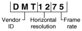
58 Chapter 4 Working with Formats
Double clocking
• i2x = double-clocked interlace (scene may change between fields) pixels are
double-clocked for DVI compatibility)
Frame rate
Frame rate is optional. If no frame rate is given, then the frame rates are assumed.
• 24 = 24 Hz
• 60 = 60 Hz
Common component TV formats
• 480pLH Component SDTV signal containing letterboxed 16x9 high-definition content
• 480pSH Component SDTV signal containing anamorphically under-sampled 16x9
content
Computer display format names
Computer display formats are assumed to use progressive scanning. In computer format
naming, the first three characters indicate the vendor ID using the EISA ID (for example,
IBM, SUN, VSC) or the display type, the next two characters indicate the approximate
horizontal resolution, the next two digits indicate the frame rate (which will be half the field
rate with interlace scanning), and the final character designates the aperture (used only
when the aperture is not A).
Example
Vendor ID (EISA)
• SMT for VESA (digital) Safe Mode Timing
• DMT for VESA Standard Discrete Monitor Timing
• GTF for VESA Generalized Timing Format standard
• CEA for Consumer Electronics Association
• EIA for Electronics Industries Association (CEA)
Approximate horizontal resolution examples
• 02 for 256 pixels
• 09 for 960 pixels
802BT/802R Video Test Generator User Guide 59
• 12 for 1200 pixels
• 30 for 3072 pixels
Frame rate examples (half the field rate with interlace scanning)
• 48 for 48Hz
• 60 for 60Hz
• 75 for 75Hz
Aperture (used only when the aperture is not A)
See “Aperture designators” on page 59.
Common computer display formats
• VSC1275 for Viewsonic 1280 by 1024 at 75 Hz
• DMT0685 for Discrete Monitor Timing with 680 by 480 at 85 Hz
Aperture designators
Format names may include one or two characters that describe the aperture of the display.
These are listed below.
Aspect ratio
• Q = 1.00:1 Quadrate - MIL, Radiology (square, 512x512, 1024x1024)
• G = 1.25:1 Graphics workstation (5x4, 1280x1024, 1600x1280)
• A = 1.33:1 Academy (4x3, 640x480, 800x600, 1024x768, 1280x960, 1600x1200)
• B = 1.44:1 Big (13x9, IMAX™)
• T = 1.50:1 Three halves (3x2, 1152x768 Apple Computer)
• V = 1.56:1 PALplus WWS case #2 (14x9, see ITU-R BT.1119)
• D = 1.60:1 VESA CVT proposed (16x10, 1728x1080, 1280x800)
• E = 1.67:1 European film (15x9 or 5x3, 1200x720, 1280x768, 1800x1080, a.k.a. “1.66”)
• H = 1.78:1 High-definition image (16x9, 1280x720,1920x1080)
• F = 1.85:1 US film (320x173, 1280x692, 1920x1038)
• U = 2.00:1 Univisum™ (2x1, 1280x640, 1920x960)
• C = 2.39:1 CinemaScope™ (160x67, 1280x536, 1920x804, a.k.a. “2.35”, was 2.35
before 1971)
Content fitting operators
• N = Natural (do nothing)
60 Chapter 4 Working with Formats
• L = Letterbox (linear scale to fit one axis, center w/black bars in other)
• Z = Zoom (blow- up to fill destination aperture with cropping, or LI )
• S = Scope (under-sample content horizontally)
• W = Widescreen (over-sample content horizontally)
• J = Justify (non- linear horizontal expand – more near edges)
• K = Keep safe (shrink to avoid cropping – provide safe title)
• P = Pan & Scan (truncate)
• M = Mirror (horizontally – rear projection)
Other Modifiers
• I = Inverse (undo operator; for example, S = Scope and SI = Inverse Scope)
• O = Orthogonally (rotate operator effect or aperture 90 degrees)
• X = Wildcard or special
Using legacy format names
You can configure the generator to display names using conventions from older generator
models.
Important: Configuring the generator to use legacy names will delete all user-defined
video formats currently stored in the generator. Therefore, it is important to back up the user
data files from the generator to disk and then restore them back to the generator. VGM can
be used to backup the generator.
To display legacy format names:
1. Turn the generator off.
2. Hold down the G key, and then power on the generator.
The following message appears on the front panel LCD.
3. Release the G key. This setting is retained throughout subsequent power cycles.
To re-assert the default format names you must reinitialize the generator:
1. Turn the generator off.
2. Hold down the ACS and DSS keys and then power on the generator.
802BT/802R Video Test Generator User Guide 61
Viewing the format library
You can view the list of formats available in the generator using VGM or the command line
interface. Please refer to the VGM online help for instructions on using VGM to view the
format list.
To display the format list:
1. Establish a terminal session with the generator.
2. Load the default format directory (fmt) or custom format directory by entering the
following command:
DIRL fmt
3. List the contents of the format directory by entering the following command:
NAMQ? 1 200 // lists the formats from the first format through 200
Viewing format details
You can view the format parameters of any standard or custom format using VGM or the
command line interface. Please refer to the VGM online help for instructions on using VGM
to view format details. Use the following procedure to view the detailed format information
through the command line interface.
To view formats parameters using the Format image:
1. Connect the generator with a display.
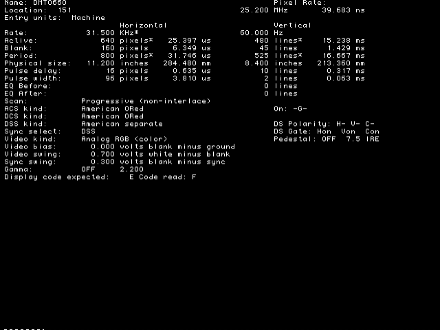
62 Chapter 4 Working with Formats
2. Load the Format image.
Information about the current format is displays.
3. Press the Step key, then turn Image knob to view additional formats.
To display individual format parameters:
1. Establish a terminal session with the generator.
2. Load the format whose parameters you want to view by entering the following
command:
FMTL format; FMTU //specify a valid format name
3. Enter the format parameter(s) you want to view. For example, to view the horizontal
resolution, vertical resolution, horizontal period, and analog video sync type, enter the
following command:
HRES? VRES? HTOT? AVST?
The generator responds with the information in sequence as shown below:
640;480;800;2
802BT/802R Video Test Generator User Guide 63
Creating custom formats
You can create new signal formats for the generator and add them to non-volatile memory.
You can create formats through VGM or by using a command line interface (either the
RS-232 port or the IEEE-488 port). The recommended procedure for creating new formats
is to use VGM. VGM contains the algorithms for ensuring compatibility between format
parameters where there are dependencies in their respective values. Please refer to the
VGM online help for information about creating formats using VGM.
Determining the signal specifications of the display
Your custom format will be based on the specifications of the display under test. Typically,
you can find the information required for the format in the detailed specification sheet for
the display. At a basic level, you must determine if you are working with an analog or a
digital display. An analog display can show an endless range of colors or shades of gray.
Analog displays normally accept video signal levels in the 1 Vp-p range. Digital displays
are more limited and can display only a few gray levels or a limited number of pre-defined
colors. These displays normally accept TTL video signals in the 4 Vp-p range.
Creating custom formats using the command line interface
There are two methods for creating formats through the command line interface. The first
method is to use the FMTN command to set all format parameters in the format buffer to
their default values, and then modify each value. The second method is to select an
existing format to use as a template for the new format, and then modify only the values
needed to create the new format. When using this method, you can save the new format
under a new name or the existing name.
Independent of the method you choose, you can enter each command interactively or,
using your computer, create a text file containing all the commands you want to issue, and
then download the text file to the generator. For instructions on creating and downloading
text files, see “Sending commands from text files” on page 16.
Creating a new format
The FMTN command is used in creating a new format. This command sets all of the
format parameters to known, default values. For a list of the parameters and their default
values, see “FMTN” on page 331. Use the following procedure to create a new format
using interactive commands.
64 Chapter 4 Working with Formats
To create a new format:
1. Establish a terminal session with the generator. See “Setting up a terminal connection
with the generator” on page 14.
2. Enter the following commands to initialize all parameters to default values and begin a
format editing session:
FMTN // initializes all parameters to default values
FMTB // begins a format editing session
3. Enter the format parameter commands in sequence to set the values for the new
format.
HRES 654 // sets the horizontal resolution to 654 pixels
.
. // other format parameters
.
HTOT 720 // sets the horizontal total to 720 pixels
Note: You do not need to enter a parameter value if it matches the FMTN default
setting.
4. End the editing session and save the new format using the following commands:
FMTE // ends a format editing session
FMTA new_fmt_name // saves format as new specified name
5. Assign the format to the knob list using the following commands:
DIRL FMT // loads format directory into edit buffer
DIRB // begins a directory edit session
NAMI 20 new_fmt_name // assigns format to format knob list at 20
DIRE // ends a directory editing session
DIRS // saves contents of directory as current name
Creating a format based on an existing format
Use the following procedure to create a format based on an existing format using
interactive commands.
To create a custom format based on an existing format:
1. Determine the signal specifications of the display under test and select an existing
format in the generator’s format library whose parameter values are similar.
2. Connect the display to the generator.
3. Using the Format knob, select the format you want to use as a template for the new
format.
4. Using the Image knob, select the Format image to view the parameters of the selected
format.
5. Establish a terminal session with the generator.
802BT/802R Video Test Generator User Guide 65
6. Enter the following commands to load and begin editing the existing format.
FMTL format_name // loads existing format into the format editor
FMTB // begins a format editing session
7. Enter the format parameter commands in sequence where the new values differ from
the existing format values. For example to modify the horizontal resolution enter the
following command:
HRES 654
Note: You do not need to enter parameter values if they match the existing format.
8. End the editing session and save the new format using the following commands:
FMTE // ends a format editing session
FMTA new_fmt_name // saves format as new specified name
9. Assign the format to the knob list using the following commands:
DIRL FMT // loads format directory into edit buffer
DIRB // begins a directory edit session
NAMI 20 new_fmt_name // assigns format to format knob list at 20
DIRE // ends a directory editing session
DIRS // saves contents of directory as current name
Modifying existing formats
The following procedure demonstrates how to modify the parameters of an existing format
using the command interface. This example changes an existing digital format from RGB
4:4:4 to YCbCr 4:2:2, and saves the format into the default format directory.
To edit an existing format:
1. Establish a terminal session with the generator.
2. Set the generator to digital friendly mode:
SROP 2 (or SROP 2 4) // sets generator to digital friendly mode
SROP 8 // sets generator to status display mode
3. Load and begin editing the format:
FMTL existing_format // loads existing format into format editor
FMTB // begins a format editing session
4. Enter the format parameter commands in sequence where the values differ from the
default values. For example to modify the component video type enter the following
command:
DVST 14 // changes the component color to YCbCr
DVSM 2 // changes component color make up to 4:2:2
ALLU // loads hardware and outputs new signal
5. End the editing session and save the format using the following commands:
FMTE // ends the format editing session
66 Chapter 4 Working with Formats
FMTA new_fmt_name // saves format as new specified name
6. Assign the format to the knob list using these commands:
DIRL FMT // loads format directory into edit buffer
DIRB // begins a directory edit session
NAMI 20 new_fmt_name // assigns new format to format knob list at 20
DIRE // ends a directory editing session
DIRS // saves contents of directory as current name
7. Load the new format using these commands:
FMTL new_fmt_name // loads new format in edit buffer
FMTU // applies new format to the generator
802BT/802R Video Test Generator User Guide 67
Editing Format knob lists
Stepping through all of the available formats using the Format knob can be time
consuming. This is particularly true if you regularly use only a few formats that may be
scattered throughout the list. You can set up the 802 to show only the formats you want, in
the order you want, when you turn the Format knob. The 802 maintains a list of these
formats in non-volatile memory, and you can edit the list to include formats you have
created and to remove any unneeded formats. You can edit the Format knob list using the
internal editor or the command line interface; however, the most convenient way to edit the
list and create custom knob lists is through VGM. Please refer to the VGM online help for
instructions on creating and editing format knob lists.
The default Format knob list is named fmt. In addition to editing this list, you can also
create new lists and name them to reflect their uses at your site.
Editing format knob list using internal editor
Use the following procedures to edit the format knob list using the internal format editor.
To edit the format knob list:
1. Power-up the generator while holding down the Image key until programmer is
displayed.
2. Select the FmtList image.
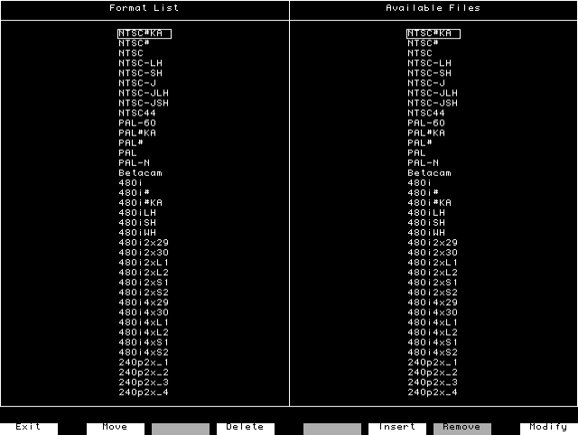
68 Chapter 4 Working with Formats
3. Press the Step key to start the Format List editor.
The left side of the screen shows the current contents of the format list. The formats
appear in the order that they are selected by the Format knob during normal operation.
The right side of the screen shows the available formats.
4. Use the Format and Image knobs to select formats in the lists. Use these commands
to edit the format list.
5. Press the Exit (Step) key to save the edited list and exit the editor.
Key Function
Insert (DCS) Inserts the format selected from the list of available files at the cursor
position in the format list.
Delete (B) Remove the selected format from the format list.
Move (R) Moves the selected format in the format list to another position in the list.
To move the selected format, press Move, use the Format knob to spec-
ify the target position, and then press the Move key again.
Remove (DSS) Deletes the format selected in the list of available formats. This will
erase the entire contents of the file from non-volatile memory. Since this
operation can destroy a lot of programming work, an on-screen mes-
sage will ask you to confirm the removal of the file. Pressing the Yes or
OK key will erase the file. Pressing the No or Cancel key will abort the
removal operation.
802BT/802R Video Test Generator User Guide 69
Editing format knob list using command line interface
Use the following procedures to edit the format knob list and create new knob lists through
the command line interface.
To insert a format at a specific location in a format knob list:
1. Establish a terminal session with the generator.
2. Create a format and save it to the generator (see “Creating custom formats” on page
63.)
3. Enter the following commands:
DIRL fmt // loads default format list (fmt)
DIRB // begins a directory editing session
NAMI 257 MyFormat // inserts format named MyFormat at position 257
DIRE // ends the directory editing session
DIRS // saves contents of directory as current name
To remove a format from a specific location in the format knob list:
DIRL fmt // loads default format list (fmt)
DIRB // begins a directory editing session
NAMK MyFormat // deletes format named MyFormat
DIRE // ends the directory editing session
DIRS // saves contents of directory as current name
To create a new format knob list, enter the following commands:
DIRL fmt // loads default format list (fmt)
DIRB // begins a directory editing session
NAMK format_1 // deletes format_1
.
. // deletes other formats
.
NAMK format_x // deletes format_x
NAMI 1 new_format_1 // inserts new_format_1 at location 1
.
. // insert other formats
.
NAMI x new_format_x // inserts new_format_x at location x
DIRE // ends the directory editing session
DIRA new_fmt // saves new format list as new_fmt
To apply a new format knob list:
FMTP new_fmt // loads format list new_fmt

70 Chapter 4 Working with Formats
Configuring DCS priority scheme
There are two priority schemes for putting composite sync (CS) on the separate VS and
HS sync outputs when digital composite sync (DCS) is selected through types SSST = 2,
6, or 11. This applies to both the VS and HS pins of the VGA connector and to the analog
component BNC connectors.
• Legacy DSC priority scheme
• Default DSC priority scheme
The following table describes the legacy DCS priority scheme for horizontal sync.
The following table describes the legacy DCS priority scheme for vertical sync.
OUTG SSST HSPG VSPG HS Output HS Polarity
0 Do not care Do not care Do not care No signal Do not care
1 Do not care 0 Do not care No signal Do not care
Do not care 8 (DPMS –
OFF)
Do not care Do not care No signal Do not care
19 (DPMS –
SUSPEND)
Do not care Do not care Horizontal
Sync
HSPP
1 10 (DPMS –
STANDBY)
Do not care Do not care No signal Do not care
1 1, 3, 5, 7, or 11 1 Do not care Horizontal
Sync
HSPP
1 2, 6, or 11
(DCS)
1 Do not care Composite
Sync
HSPP
OUTG SSST HSPG VSPG VS Output VS Polarity
0 Do not care Do not care Do not care No signal Do not care
1 Do not care Do not care 0 No signal Do not care
Do not care 8 (DPMS –
OFF)
Do not care Do not care No signal Do not care
19 (DPMS –
SUSPEND)
Do not care Do not care No signal Do not care
1 10 (DPMS –
STANDBY)
Do not care Do not care Vertical Sync VSPP
1 1, 3, 5, 7, or 11 Do not care 1 Vertical Sync VSPP
1 2, 6, or 11
(DCS)
1 Do not care No signal Do not care
1 2, 6, or 11
(DCS)
01Composite
Sync
VSPP

802BT/802R Video Test Generator User Guide 71
The following table describe the default DCS priority scheme for horizontal sync.
The following table describe the default DCS priority scheme for vertical sync.
To enable the legacy DCS priority scheme:
1. Turn off the generator.
2. Hold down the Step and DCS keys while starting the generator.
The generator will remain in this mode through subsequent power cycles until the
generator is re-initialized or reset with the “No special modes” command (hold down
ACS+DCS+DSS while starting the generator).
OUTG SSST HSPG HS Output HS Polarity
0 Do not care Do not care No signal Do not care
1 Do not care 0 No signal Do not care
Do not care 8 (DPMS – OFF) Do not care No signal Do not care
1 9 (DPMS – SUS-
PEND)
Do not care Horizontal Sync HSPP
1 10 (DPMS –
STANDBY)
Do not care No signal Do not care
1 1, 3, 5, 7, or 11 1 Horizontal Sync HSPP
1 2, 6, or 11 (DCS) 1 Composite Sync CSPP
OUTG SSST VSPG VS Output VS Polarity
0 Do not care Do not care No signal Do not care
1 Do not care 0 No signal Do not care
Do not care 8 (DPMS – OFF) Do not care No signal Do not care
1 9 (DPMS – SUS-
PEND)
Do not care No signal Do not care
1 10 (DPMS –
STANDBY)
Do not care vertical Sync VSPP
1 1, 3, 5, 7, or 11 1 vertical Sync VSPP
1 2, 6, or 11 (DCS) 1 Composite Sync CSPP
72 Chapter 4 Working with Formats
Creating format aliases
You can create aliases for formats to suit the needs of your site. Use the following
procedure to create an alias for a format, save it to the format directory, and then use the
alias.
To create and use a format alias:
1. Establish a terminal session with the generator.
2. Enter the following commands:
ALIN your_alias format // assigns alias to format
DIRL FMT // loads default format list (fmt)
DIRB // begins a format editing session
NAMI 1 “your_alias” // assigns alias to format directory
DIRE // ends a format editing session
DIRA FMT // saves alias in default format directory
To delete a format alias, enter the following command:
ALIK your_alias // removes the alias
74 Chapter 5 Working with Images
Overview
The 802R/BT includes a library of 250 test images. In addition, you can create custom
images, which consist of one or more drawing primitives, including single pixel dots, lines,
rectangles, and ovals. You can select the grayscale and color tables used in the image and
save the images in non-volatile memory. Custom images can be added to the list of built-in
images that can be selected with the Image knob. You can create and edit test images and
edit the Image knob list using the Video Generator Manager (VGM) application or the
command line interface. Please refer to the VGM online help for details on creating custom
images using VGM.
The following functions are provided:
•Creating images. You can create your own custom images and add them to the image
library.
•Downloading bitmap images. You can also create your own images in other
applications and save them as bitmap files which can then be downloaded using a
terminal emulator or from a PCMCIA card.
•Editing the Image knob list. You can edit the Image knob list to include any
combination of built-in and custom images. The default operating mode of the 802 uses
the Image knob to select images from an internal list of built-in images.
•Setting up a looping image display. You can set up a continuous cycling mode that
draws images one-after-another in an infinite loop. Image looping can be used for
burn-in testing or for running single-mode displays at trade shows.
•Creating aliases. You can assign your own names to images using aliases.
Viewing the image list
You can view the list of images available in the generator using VGM or the command line
interface. Please refer to the VGM online help for details on viewing the image list using
VGM. Use the following procedure to view the image list using the command line interface.
To display the image list:
1. Establish a terminal session with the generator. See “Setting up a terminal connection
with the generator” on page 14.
2. Load the default image directory (img) or custom image directory by entering the
following command:
DIRL IMG
3. List the contents of the image directory by entering the following command:
NAMQ? 1 200 // lists the images from the first through 200
802BT/802R Video Test Generator User Guide 75
Creating custom images
This section describes how to create images and add them to the generator’s image
library, and how to customize the image list. The recommended method for creating
images is create a text file containing the commands for creating the image, and then
downloading the text file to the generator. Another method for creating images is to use
the Image Editor in VGM to create a basic image, save the basic image as a command file
in VGM, and then open and edit the command file to refine the image as needed.
To create custom images with a command file:
1. Using a text editor, open a text file (command file) on your computer and enter the
following commands.
OUTG 0 // gates all video and sync outputs off
IMGN new_image // creates a new image
IMGB // begin an image editing session
XRES 640 // sets the horizontal resolution
YRES 480 // sets the vertical resolution
.
. // other image parameters
.
IMGE // ends an image editing session
IMGA new_image // saves image as new_image
OUTG 1 // gates all video and sync outputs on
IMGU // draws the image
ALLU // applies the buffer to the generator hardware
2. Save the text file, using a *.txt extension.
3. Establish a terminal session with the generator. See “Setting up a terminal connection
with the generator” on page 14.
4. At the R:> prompt, transfer the text file to the generator. For example, to transfer a file
using HyperTerminal, do the following:
a. On the Transfer menu, click Send Text File. The Send Text File dialog box
appears.
b. Select the text file you want to send, and then click Open. HyperTerminal displays
the commands as they are sent.
c. Press Enter once to ensure that the last command is sent.
5. Assign the image to Image knob list by entering the following commands:
DIRL IMG // loads image directory into edit buffer
DIRB // begins a directory editing session
NAMI 20 new_image // assigns image to image knob list at 20
DIRE // ends a directory editing session
DIRS // saves contents of directory as current name
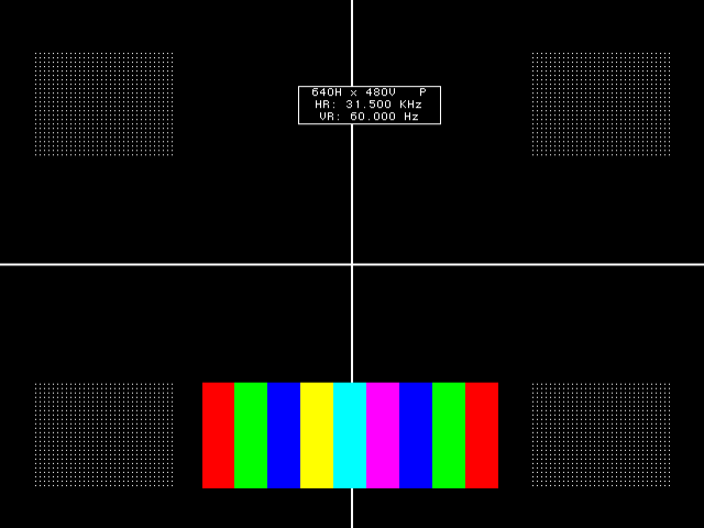
76 Chapter 5 Working with Images
Command file example
The following sample command file creates the image shown in the graphic below.
Commands used to draw image above:
IMGN
IMGB // begin an editing session
XRES 640 // set the horizontal resolution
YRES 480 // set the vertical resolution
HATO Foreground 24 18
OVAL Foreground 479 479 80 0 GrayPat0
CROS White
RECT White 205 154 770 77 GrayPat50
RECT Black 128 96 30 45 GrayPat100
RECT Black 128 96 482 45 GrayPat100
RECT Black 128 96 30 345 GrayPat100
RECT Black 128 96 482 345 GrayPat100
RECT Red 30 96 184 347 GrayPat100
RECT Blue 30 96 243 347 GrayPat100
RECT Yellow 30 96 273 347 GrayPat100
RECT Cyan 30 96 303 347 GrayPat100
RECT Magenta 30 96 333 347 GrayPat100
RECT Blue 30 96 363 347 GrayPat100
FORM White 271 78
RECT Green 30 96 213 347 GrayPat100
RECT Green 30 96 393 347 GrayPat100
RECT Red 30 96 423 347 GrayPat100
RECT White 128 96 30 45 GrayPat7
RECT White 128 96 482 45 GrayPat7
RECT White 128 96 30 345 GrayPat7
RECT White 128 96 482 345 GrayPat7
802BT/802R Video Test Generator User Guide 77
IMGE // end an editing session
IMGA MyImage // save image as MyImage
78 Chapter 5 Working with Images
Downloading bitmap images from a PCMCIA card
This section describes how to store a bitmap image on a standard PCMCIA memory card,
and then load the image as you would a built-in image. The generator can load only one
image from a card. Although you can download an image using VGM, loading an image
from a card is faster and easier.
This feature is supported on 802BT and 802R generators with video board FPGA 91 or
later, DVI daughter card FPGA 0xE3 or later, and firmware 7.3834000 or later (802BT) or
7.38180000 or later (802R). To determine your generator specifications, “Displaying
system information” on page 44.
To copy an image onto a card:
1. Save the image you want to store on the card as an 8-bit or 32-bit (24-bit TrueColor)
bitmap (.bmp) file on your computer using any file name.
2. Hold down the ACS, DCS, and DSS keys, and then cycle the power to the generator.
This removes any special modes and sets the baud rate of the serial port to 2400 bps.
3. Establish a terminal session with the generator and change the baud rate of the
generator to 38400 bps (see “Changing the baud rate” on page 15.)
4. Insert a PCMCIA card into the slot in the generator.
5. At the R:> prompt, enter the following command to initiate the YMODEM-BATCH
file-upload protocol:
YMDI
6. At the R:> prompt, transfer the file to the card. For example, to transfer a file using
HyperTerminal, do the following:
a. On the Transfer menu, click Send File. The Send File dialog box appears.
b. In the Filename box, click Browse and select the bitmap file you want to copy to
the generator.
c. In the Protocol box, click the down arrow and select Ymodem.
d. Click Send.
Note: You must send the image within about 15 seconds after sending the YMDI
command. If the R:> command prompt appears before you send the image, send the
YDMI command again, and then send the image again.
For descriptions of any error codes displayed, see Appendix C, “Error Messages.”
To view an image stored on a PCMCIA card:
1. Insert the card that contains the image you want to view.
802BT/802R Video Test Generator User Guide 79
Note: The card you need is a Type 1, Battery Backed RAM PCMCIA card with at least
2 MB of storage. These cards are available from synchrotech P/N PCM-SRW-AM002
2MB. Flash or compact type memory cards will not work.
2. Use one of the following procedures to configure the generator to use a format with the
same pixel depth as the image:
• Select a built-in format with the appropriate pixel depth.
• Create a format with the appropriate pixel depth.
• Establish a terminal session with the generator and enter the following commands
to set the pixel depth to 32-bit (24-bit TrueColor) or 8-bit:
PELD 32; ALLU
or
PELD 8; ALLU
• Hold down the R key while pressing and releasing the G key to toggle the pixel
depth between 8 and 32-bit pixel depths.
3. Using the Image knob, select the CardBMP image, or enter this command:
IMGL CardBMP; ALLU
The image appears on the display.
4. To view an image from a different card, switch the cards, and then re-select the
CardBMP image.
80 Chapter 5 Working with Images
Looping through images
You can set up a continuous cycling mode that draws all images in the image knob
listone-after-another in an infinite loop. When activated, the message “Loop Enabled”
appears on the display under test.
To enable image looping:
1. Using the Format knob, select a format compatible with the display under test.
2. Turn the Image knob clockwise beyond the last image in the Image list about one turn.
The message “Loop Enabled” appears on the display under test. After a second or two,
the first image in the cycle appears and the generator continuously cycles through the
test image list using a given format in this mode.
To disable image looping:
1. Turn the Image knob counter-clockwise to stop image looping.

802BT/802R Video Test Generator User Guide 81
Editing Image knob list
If your test environment requires only a subset of the available built-in images, you can
configure the 802 to show only the images you want, in the order you want, when the
Image knob is turned. The 802 maintains a list of these images in non-volatile memory.
You can edit this list to include images you have created and to remove unneeded images.
The Image knob list can be edited using the command line interface; however, the most
convenient way to edit the knob list and create custom knob lists is using VGM. Please
refer to the VGM online help for procedures on editing image knob lists.
The default Image knob list is named img. In addition to editing this list, you can also
create new lists and name them to reflect their uses at your site.
Editing image knob list using internal editor
Use the following procedures to edit the image knob list using the internal image editor.
To edit list of images:
1. Power-up the generator while holding down the Image key until programmer is
displayed.
2. Select the ImgList image.
3. Press the Step key to start the image list editor.
The left side of the screen shows the current contents of the image list. The images are
listed in the order that they are selected by the Image knob during normal operation.
The right side of the screen shows all of the available images. The built-in images are
at the top of the list, followed by a factory default custom image. This image is used as
starting point to creating you own custom images. Any user-defined images in
non-volatile memory are at the bottom of the list.
4. Use the Format and Image knobs to select images in the lists. Use these commands
to edit the image list.
Key Function
Insert (DCS) Inserts the image selected in the list of available files before the image
selected in the image list.
The current firmware does not allow entering a secondary version of a
built-in image to the list. The primary version will need to be first
selected during normal operation. Pressing the Image key will then
select the secondary version.
Delete (B) Remove the selected image from the image list.

82 Chapter 5 Working with Images
5. Press the Exit (Step) key to save the list and exit the editor.
Editing Image knob list using command line interface
Use the following procedures to edit the Image knob list and create new knob lists through
the command line interface.
To insert an image at a specific location in the default image knob list:
1. Establish a terminal session with the generator.
2. Create a custom image and save it to the generator. See “Creating custom images” on
page 75.
3. Enter the following commands:
DIRL img // loads default image list called img
DIRB // begins a directory editing session
NAMI 111 MyImage // inserts image named MyImage at position 111
DIRE // ends the directory editing session
DIRS // saves the contents of directory as current name
To remove an image from a specific location in the image knob list:
DIRL img // loads default image list called img
DIRB // begins a directory editing session
NAMK MyImage // deletes image named MyImage
DIRE // ends the directory editing session
DIRS // saves the contents of directory as current name
To create a new image knob list:
DIRL img // loads default image list called img
DIRB // begins a directory editing session
NAMK image_1 // deletes image named image_1
.
. // deletes other images
.
NAMK image_x // deletes image_x
NAMI 1 new_image_1 // inserts new_image_1 at location 1
.
. // inserts other images
.
NAMI x new_image_x // inserts new_image_x at location x
Move (R) Moves the image selected in the image list to another position in the list.
To move the selected image, press Move, use the Format knob to spec-
ify the new position, and then press the Move key again.
Remove (DSS) Deletes the selected user-defined image from the list of available files.
This will erase the entire contents of the file from non-volatile memory.
Standard images cannot be deleted.
Key Function
84 Chapter 5 Working with Images
Creating image aliases
You can create image aliases to suit the needs of your site. Use the following procedure to
create an alias for an image, save it to the image directory, and then use the image.
To create and use an image alias:
1. Establish a terminal session with the generator.
2. Enter the following commands:
ALIN your_alias image // assigns alias to image
DIRL IMG // loads default image list (img)
DIRB // begins an image editing session
NAMI 1 “your_alias” // assigns alias to image directory
DIRE // ends an image editing session
DIRA IMG // saves alias in default image directory
To delete an image alias:
Enter the following command:
ALIK your_alias // removes the alias
86 Chapter 6 Working with Test Sequences
Overview
When testing video displays, you typically select a format using the Format knob, and then
select an image using the Image knob. In a production environment, where there might be
a need to test several combinations of formats and images, you can create a test
sequence to automate the process of selecting formats and images. Test sequences
provide a way to progress through a pre-defined sequence of format and images, either
manually or automatically.
You can create test sequences using the command line interface, the internal sequence
editor or the Video Generator Manager (VGM) application. This section describes how to
create and run test sequences using the command line interface and internal sequence
editor. Please refer to the VGM online help for instructions on defining and running a test
sequence from VGM.
The following functions are provided:
• Create your own custom test sequences consisting of multiple steps. Each step
specifies the format and image to display as well as the duration of the step. You can
create multiple sequence files, which are stored in non-volatile memory.
• Program the 802R/BT generator to run in test-sequence mode on power-up. This mode
of operation is useful in a manufacturing test environment where the same test
procedure must be repeated on many identical displays. Multiple test sequences can
be stored in the generator and selected by the operator.
802BT/802R Video Test Generator User Guide 87
Creating a test sequence
You can create a test sequence using the command line interface, the generator’s built-in
editor or VGM.
Creating a test sequence using command line
You can develop test sequences either by entering command interactively through a
terminal session or by entering a series of commands in a text file and then send them to
the generator through hyper terminal. When developing long test sequences, the
recommended procedure is to enter commands in a text file, and then send the file to the
generator. This approach enables you to change the test sequence without entering the
entire command script.
Use the following procedure to create a test sequence, save it to the sequence directory,
and then run it using the command line interface.
To create and save a test sequence interactively using the command line interface:
1. Establish a terminal session with the generator.
2. Enter the following commands to create a three-step sequence named MySeq.
SEQN // initializes the sequence edit buffer
SEQB // begins a sequence editing session
STEP 1 // selects a step to be edited
SDLY 5.0 // sets the delay for the current step to five seconds
FMTL 480p59 // loads a format
IMGL SMPTEbar // loads an image
STEP 2 // selects a step to be edited
SDLY 5.0 // sets the delay for the current step to five seconds
FMTL 720p60 // loads a second format (same image)
IMGL Outline1 // loads an image
STEP 3 // selects a step to be edited
SDLY 5.0 // sets the delay for the current step to five seconds
FMTL 1080i29 // loads a third format
IMGL Geom_4 // loads another image
SEQE // ends the sequence editing session
SEQA MySeq // saves the current contents of the sequence editor
To create and save a test sequence from a text file:
1. Using a text editor, open a text file (command file) on your computer and enter the
following commands to create a three-step sequence named MySeq.:
SEQN // initializes the sequence edit buffer
SEQB // begins a sequence editing session
STEP 1 // selects a step to be edited
SDLY 5.0 // sets the delay for the current step to five seconds
FMTL 480p59 // loads a format
88 Chapter 6 Working with Test Sequences
IMGL SMPTEbar // loads an image
STEP 2 // selects a step to be edited
SDLY 5.0 // sets the delay for the current step to five seconds
FMTL 720p60 // loads a second format (same image)
IMGL Outline1 // loads an image
STEP 3 // selects a step to be edited
SDLY 5.0 // sets the delay for the current step to five seconds
FMTL 1080i29 // loads a third format
IMGL Geom_4 // loads another image
SEQE // ends the sequence editing session
SEQA MySeq // saves the current contents of the sequence editor
2. Save the text file, using a *.txt extension.
3. Establish a terminal session with the generator.
4. Transfer the text file to the generator. For example, to transfer the file using
HyperTerminal, do the following:
a. On the Transfer menu, click Send Text File. The Send Text File dialog box
appears.
b. Select the text file you want to send, and then click Open. HyperTerminal displays
the commands as they are sent.
c. Press Enter once to ensure that the last command is sent.
To insert a sequence at a specific location in the sequence list:
1. Establish a terminal session with the generator.
2. Enter the following commands:
DIRL seq // loads sequence directory into edit buffer
DIRB // begins a directory editing session
NAMI 1 MySeq // assigns sequence to sequence list at 1
DIRE // ends the directory editing session
DIRS // saves contents of directory as current name
Creating and editing test sequences using the internal editor
You can use the generator’s internal Sequence Editor to create, edit and run test
sequences without using VGM. The 802 can be configured to allow an operator to run only
certain sequence files in the sequence mode. The 802 maintains a list of these accessible
sequences in non-volatile memory. You will need to edit the list if you wish to add
sequences you have created. The procedures for creating and editing the sequence file
list are provided below.
To create a test sequence using the internal sequence editor:
1. Turn on the generator while pressing the Image key until programmer is displayed.
2. Select the SeqList image.
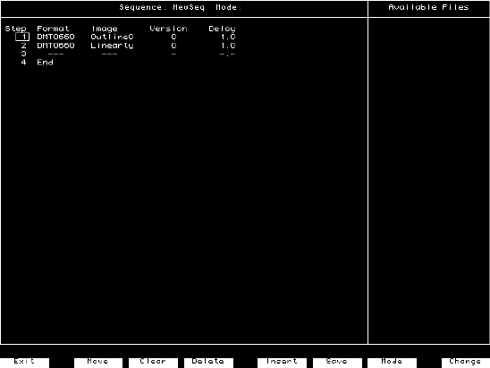
802BT/802R Video Test Generator User Guide 89
3. Press the Image key to start the Sequence List editor.
4. Use the Image knob to select a sequence file from the list of available files. NewSeq is
provided by default to serve as a template.
5. Press the Insert key (DCS) to insert the NewSeq file into the sequence list.
6. Use the Format knob to select the NewSeq file, and then press the Modify key.
7. Use the Format knob to select the field you want to edit. Use the Image knob to select
field values.
Press Change (Outputs) to apply the selected value.
Press Insert (ACS) to insert a new step.
Press Clear (G) to delete all steps.
Press Delete (B) to delete the selected step.
To move the selected step, press Move (R), then use the Format knob to select the
target position, and then press Move again.
8. Press Mode (DSS) to specify how the generator should run the sequence file when the
generator is started. If you have multiple sequence files, the file with the most recent
mode setting you make will apply upon startup. Setting the mode for a file will

90 Chapter 6 Working with Test Sequences
deactivate the mode status of all other sequence files. If a start-up mode is not set for
any sequence file, then the generator will start in the normal operating mode.
9. Press Save (DCS) to save the sequence file. Use the Format and Image knobs to
specify a name for the file by selecting the characters presented.
10. Press Exit (Image) to exit the Sequence Editor, and to return to the Sequence List
editor.
To edit the list of sequences that can be used:
1. Hold down the Image key while starting the generator, until programmer is displayed.
2. Select the SeqList image.
3. Press the Image key to start the Sequence List editor.
The Sequence List box shows a list of sequence files that can be selected with the
Format knob. The Available Files box shows all sequence files available.
Mode Display option Description
blank If no mode is specified the sequence is not started when the
generator is started.
step Use the Image knob to advance through sequence steps.
You cannot advance past the last step. However, rotating the
Image knob forward one revolution past the last step will
change the mode to automatic. Rotating the Image knob
backward one revolution changes the mode back to manual.
Step information is displayed on the LCD only.
step -s# Current step number is displayed with image on display
being tested.
step -display Complete step information (sequence name, format, image,
and step number) is displayed with image on display being
tested.
wrap Use Image knob to advance through sequence steps.
Advancing past the last step restarts at the first step.
Step information is displayed on the LCD only.
wrap -s# Current step number is displayed with image on display
being tested.
wrap -display Complete step information is displayed with image on dis-
play being tested.
auto Automatically and continuously cycles though sequence
steps, and displays step information on LCD only.
auto -s# Current step number is displayed with image on display
being tested.
auto -display Complete step information is displayed with image on dis-
play being tested.

802BT/802R Video Test Generator User Guide 91
4. Use these controls to edit the list of sequence files.
5. Press Exit to save the list, and to exit the editor.
Control Description
Move Use the Format knob to select the file you want to move, press Move, then use
the Format knob to specify the target location, and then press Move again.
Delete Removes the selected sequence file from the sequence list.
Insert Inserts the sequence file selected from the list of available files into the
sequence list.
Remove Deletes the sequence file selected in the list of available files from non-volatile
memory.
Modify Opens the selected sequence file in the Sequence Editor.
92 Chapter 6 Working with Test Sequences
Viewing the test sequence list
You can view the list of test sequences stored in the generator using the command line
interface, the internal sequence editor or VGM.
Viewing the test sequence list using the command line
Use the following procedure to view the test sequence list using the command line
interface.
To view the sequence list using the command line interface:
1. Establish a terminal session with the generator.
2. Load the default test sequence directory (seq) or custom sequence directory using the
following command:
DIRL seq
3. List the contents of the sequence directory by entering the following command:
NAMQ? 1 4 // lists test sequences from the first through the fourth
Deleting a test sequence using the command line
Use the following procedure to delete a test sequence list using the command line
interface.
To delete a test sequence using the command line interface:
1. Establish a terminal session with the generator.
2. Load the default test sequence directory (seq) or custom sequence directory and begin
an editing session using the following commands:
DIRL seq
DIRB
3. Delete the sequence by entering the following command:
NAMK myseq
ALLU
4. End and save the sequence editing session using the following command:
DIRE
DIRS
802BT/802R Video Test Generator User Guide 93
Viewing test sequence using internal sequence editor
Use the following procedure to view the test sequence list using the internal sequence
editor.
To view the sequence list using the internal sequence editor:
1. Hold down the Image key while starting the generator, until programmer is displayed.
2. Select the SeqList image.
3. Press the Image key to start the Sequence List editor.
The Sequence List box shows a list of sequence files that can be selected with the
Format knob. The Available Files box shows all sequence files available.
94 Chapter 6 Working with Test Sequences
Running a sequence
Regardless of how you created a test sequence you can initiate it through the command
line, the built-in editor or VGM. For information on running a test sequence through VGM
refer to the VGM help. The instructions for running test sequences through the command
line or internal sequence editor are provided below.
Running a test sequence using the command line
A sequence can run in one of three modes:
• Step and stop mode, where the progression of the sequence is under user control, and
the sequence halts after the final step.
• Step and wrap mode, where the progression of the sequence is under user control, and
it continuously loops (repeats the sequence steps).
• Automatic mode, which enables automatic progression through the sequence list and
also continuous looping.
The following procedures describe how to use these modes:
To run a sequence in step and stop mode:
1. Establish a terminal session with the generator.
2. Enter the following commands:
SEQL MySeq // loads MySeq into sequence edit buffer
SMOD 1 // sets step mode to manual with stop after last step
SEQU // starts running the sequence
3. Turn the Image knob to progress through the sequence.
4. To stop the sequence, enter the following command:
SMOD 0; ALLU
To run a sequence in step and wrap mode:
1. Establish a terminal session with the generator.
2. Enter the following commands:
SEQL MySeq // loads MySeq into sequence edit buffer
SMOD 2 // sets step mode to manual with wrapping after last step
SEQU // starts running the sequence
3. Turn the Image knob to progress through the sequence.
4. To stop the sequence, enter the following command:
SMOD 0; ALLU

802BT/802R Video Test Generator User Guide 95
To run a sequence in automatic mode:
1. Establish a terminal session with the generator.
2. Enter the following commands:
SEQL MySeq // loads MySeq into sequence edit buffer
SMOD 3 // sets the sequence mode to run in auto mode
SEQU // starts running the MySeq sequence
3. To stop the sequence, hold down the ACS, DCS, and DSS keys, and then cycle the
power to the generator.
To run a sequence at power up:
1. Run the sequence in the desired mode.
2. Turn off the power to the generator.
3. Start the generator in normal operating mode (without holding down any keys).
4. Depending on the selected mode, the sequence will start automatically, or you can turn
the Image knob to move forward and backward though the sequence.
The format and image names for each step and the current step number will appear on
the LCD. Additional status information may appear before the step number, depending
on the mode. This will be S for step, W for wrap and A for automatic.
5. To stop the sequence, hold down the ACS, DCS, and DSS keys, and then cycle the
power to the generator.
To run a manual sequence continuously:
1. Rotate the Image knob a full turn clockwise beyond the last step. A message on the
LCD will confirm that the continuous cycle is running.
2. To stop the cycle, rotate the Image knob counter-clockwise. The generator will
remember if the sequence was in continuous cycle mode on power down. If so, it will
remain in continuous cycle mode when the generator is powered on.
Running a test sequence using internal sequence editor
To run a sequence, that was created using the internal sequence editor:
1. Configure one sequence file with a mode setting through the sequence editor (see
“Creating and editing test sequences using the internal editor” on page 88).
2. Start the generator in normal operating mode, without holding any keys down.
<format><seqName>
<image> <seqStep>
96 Chapter 6 Working with Test Sequences
3. Depending on the mode of the sequence, the sequence will start automatically, or you
need to turn the Image knob to move forward and backward though the sequence.
The LCD will display the format and image name for each step, and the current step
number. Additional status information may appear before the step number, depending
on the mode (manual, automatic, wrap).
A manual mode sequence can be set to continuously cycle through all the steps, by
rotating the bottom knob a full turn clockwise beyond the last step. A message on the
LCD will confirm that the continuous cycle is running. The cycle is stopped by rotating
the bottom knob counter-clockwise. The generator will remember if the sequence was
in continuous cycle on power down. If so, it will continuous cycle on power on.
If multiple sequences have been defined, use the Format knob to load other
sequences.
Note: When controlling the generator from a program, it is possible to make any
sequence the “Power-on” sequence without having it appear on the sequence knob
directory. In this case, the generator will power-up in the sequence mode with the
selected sequence, but loading a different sequence file with the Format knob, will not
allow you to get back to the original power-up sequence file.
Cancelling the start-up sequence mode
If the generator has been configured to run a sequence at start-up, and you want the
generator to start in normal operating mode, you need to power the generator up while
indicating “no special modes” (press and hold the ACS, DCS and DSS keys).
98 Chapter 7 Using GPIB Interface
Overview
You can operate and program the 802 generator from an external computer or terminal
using either the RS-232C serial port or optional IEEE-488 (GPIB) port. The GPIB port
enables the 802 to be used as a programmable video signal source for integration into
automated test systems that use IEEE-488 or GPIB communications between
instruments.
802BT/802R Video Test Generator User Guide 99
Setting the GPIB port address
The default GPIB address is 15. You can specify a different address.
To set the address of the GPIB port directly on the generator:
1. Locate the rotary switches on the back of the generator between the RS-232 port and
the GPIB port. These are accessible through the ventilation slots. There are two rotary
switches: the one on the left configures the value of the tens digit and the one on the
right configures the value of the ones digit.
2. Set the rotary switches first the value of the tens switch and then the value of the ones
switch to the desired value.
3. Hold down the DCS key, and then cycle the power to the generator. The port is set to
the new address.
Note: A normal power cycle will not update the memory to the new switch settings.
To set the address of the GPIB port using the command line:
1. Establish a terminal session with the generator
2. (Optional) Enter the following command to check the current address:
GPIB?
3. Enter the following command:
GPIB address
When the address is changed with the GPIB command, the change takes place as
soon at the command is issued.
The new address setting will be maintained until 1) the address is changed with another
GPIB command, 2) the unit is re-initialized with an INIT command, or 3) the unit is
re-initialized because the power-up self test found corrupted data in battery-backed
system memory. In cases 2 and 3, the GPIB address will revert to the address set on
the GPIB address switches if the unit has them, or to 15 if the unit does not have GPIB
address switches.
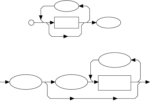
100 Chapter 7 Using GPIB Interface
Queries and commands
The GPIB interface is an ASCII command line interface like the RS-232 command line
interface. The communications protocol is per IEEE-488.2 specification. Queries and
commands consist of four ASCII upper/lower case characters. Commands do not require
a response from the generator, while queries cause the 802 to respond with the required
data.
You can send multiple commands on the same line by separating the commands with a
semicolon (;) followed by a terminator. A terminator is defined as the NL character (ASCII
10), or EOI sent with the last byte of the command. The 802 will not parse any commands
received until a terminator is received. All commands are executed sequentially; that is,
when a command is parsed it is allowed to finish execution before the next command is
parsed, as illustrated in the following figure.
Commands
Commands instruct the 802 to set a parameter to the value given or perform some
function not requiring any additional data. Commands which have an asterisk (*) as their
first character are common commands as defined by the IEEE-488.2 standard and
generally operate the same in all instruments. All commands are listed and described in
Appendix A, “Command Reference.”
Commands which do not require any additional data from the controller are self-contained
and should be followed by either a message separator (;) or message terminator. Any
other characters (except whitespace characters) will cause a command error.
Commands which require numeric data must be followed by at least one separator
character (whitespace), and then the data. Numeric data sent with a command is in
decimal format. Numeric data can be represented in one of three methods: integer,
floating point, or scaled floating point.
Message Terminator
Separator ( ; )
Program Message Syntax
Command/Query
Header
Separator
( ; )
Data
Separator
(white space)
Message Unit Syntax
802BT/802R Video Test Generator User Guide 101
For example, the following number can be represented in three ways:
• Integer (42)
• Floating point (42.00)
• Scaled floating point (4.200E+01)
Queries
Queries are comprised of a header followed immediately by a question mark (?). If there
are any characters between the query header and the question mark character (including
whitespace), a command error will result. Queries, return a response message upon
completion of execution. A response message is comprised of the requested data
terminated with an NL (ASCII 10) character. For example the following text would be
returned in response to the HRAT? (horizontal rate query) message:
3.1500E+04<NL>
Note that the HRAT? query returns its parameter in exponential form. Possible returned
parameter forms are:
• Integer (3965)
• Exponential (+3.965E+03)
• String ("text string")
Output queue
When a query is executed, the resulting response message is placed in an output queue
where it can be read by the controller. The 802 has an output queue that is 255 bytes long.
When a message is present in the output buffer, the MAV (message available) bit in the
Status Byte register is set. This varies slightly from the 488.2 standard in that the MAV bit
will be set only when at least one complete response message is present in the output
queue. A complete response message consists of response message text and a message
terminator (NL).
Buffer deadlock
Buffer deadlock occurs when the 802 tries to put a response message in the output queue
when the output queue is full and the controller is held off while sending a new message
because the input buffer is full. If deadlock occurs, the 802 will clear its output queue, set
the query error (QYE) bit in the Event Status register and proceed to parse incoming
messages. If any additional queries are requested while in deadlock, those response
messages will be discarded.
The 802 will clear the buffer deadlock when it finishes parsing the current command/query.
The QYE bit will remain set until read with the *ESR? query or cleared with the *CLS
command.
102 Chapter 7 Using GPIB Interface
Sending commands and queries
The generator parses command lines one at a time. Command lines must be terminated
with a carriage return (<cr>).The generator immediately echoes each character as it is
received and places it in a command line buffer. This buffer currently has room for a total of
256 characters. If more than 256 characters are sent before sending a <cr>, then the
following response will be given:
Buffer overflow<cr><lf><cr><lf>R:\>
Upon receiving a carriage return, the generator immediately echoes the <cr> and follows it
with a line feed (<lf>). The generator then parses the command line and initiates whatever
processing is implied. The generator then responds with one of the following four
responses depending on the condition:
Command invalid<cr><lf><cr><lf>R:\>
<message1><cr><lf><message2><cr><lf>...<messageN><cr><lf><cr><lf>R:\>
Execution error: <nnnn><cr><lf><cr><lf>R:\>
R:\>
Where <cr> and <lf> are the carriage return and line feed characters, respectively.
Note: Handshaking routines should only look for > and not R:\>. In the future, the R:\ part
of the prompt may change (for example, may be expanded to indicate the current path).
Bench-top generators output the following prompt on their serial port after finishing the
power-on procedure.
R:\>
This feature allows ATE systems to know when the generator is ready.
Sending multiple commands and queries per line
You cans send multiple commands and queries per line by separating each command or
query with a semi-colon (;) character. For example:
HTOT 900; ALLU
The response to multiple queries will be a series of data elements separated by
semi-colons (;). For example, with the VGA_m3 format loaded, the following command
string will produce the response shown.
HRES?; VRES?; VTOT?
640;480;525
Normally, all of the commands on a command line associated with a single command
terminator are read as a single command message without regard for execution or
completion order. However, by inserting the *WAI command, you can force the generator
802BT/802R Video Test Generator User Guide 103
to wait for all preceding commands to be completed before the commands that follow *WAI
are processed. For example, sending the following command line causes a red rectangle
to be drawn and then overwritten by the colorbar image.
IMGL COLORBAR; IMGU; IMGE; RECT RED 200 200 0 0 GRAYPAT100
Note that the IMGU command merely requests that the current image be rendered
eventually, not necessarily right away nor in a single attempt. By inserting a *WAI
command after the IMGU, the generator is instructed to render the colorbar image first,
before rendering the red rectangle. This command ensures that the generator draws the
red rectangle on top of the colorbar image.
IMGL COLORBAR; IMGU; *WAI; IMGE; RECT RED 200 200 0 0 GRAYPAT100
The generator will wait until the colorbar image has been completely rendered before it
reads and executes the RECT command.
The
*WAI
command is required by the IEEE-488.2-1992 standard, but also works with
GPIB and RS-232 protocols as well.
Completion handshake
The generator returns a > prompt immediately after an FMTU, IMGU, ALLU, BOOT, INIT,
or SCAL command is received, even if these commands have not finished executing. If the
system controlling the generator must know when the process started by one of these
commands has been completed, then append *OPC? to the command string.
For example, the following command causes the generator to wait until all processes have
been completed before responding with the number 1 and sending the > prompt.
FMTL VGA_M3; IMGL FLAT; ALLU; *OPC?
The *OPC? command is required by the IEEE-488.2-1992 standard, but also works with
GPIB and RS-232 protocols as well.
Input buffer
Since some commands may take longer to execute, the 802 has an input buffer. This input
buffer is 255 characters long and can be written to by the host controller while the 802 is
busy executing or parsing previous messages. If the input buffer becomes full, the 802 will
hold off the controller until there is room in the buffer. For this reason, a program message
cannot be longer than 255 characters including terminator.

104 Chapter 7 Using GPIB Interface
Status queries and control
To create applications that control the generator using the GPIB port, it is sometimes
necessary to query the status of the generator and set or reset the status bits and bytes.
There are two sets of status registers: 1) the Event Status Register and Event Status
Enable Register and 2) the Status Byte Register and Service Request Enable Register.
These are described in the following paragraphs.
Status byte
The status byte used by the 802 is the same as that defined by the IEEE-488.2 standard
and does not use any other bits of the status byte. The status byte is one part of a
complete status reporting system shown in the figure on page 105. The status byte is read
by using the serial poll feature of your controller.
Requesting service
The GPIB provides a method for any device to interrupt the controller-in-charge and
request servicing of a condition. This service request function is handled with the status
byte. When the RQS bit of the status byte is true, the 802 is requesting service from the
controller. There are many conditions which may cause the 802 to request service. For
more information about these conditions, see the *SRE command description (page 212).
The table below lists the status commands and queries.
Status commands
and queries Definition
*ESE Sets the Event Status Enable register to the given mask value. When a bit
in the Event Status register goes high and the corresponding bit in the
Event Status Enable register is a 1, it is enabled and will cause the ESB bit
in the Status Byte register to go high.
*ESE? Returns the current value of the Event Status register. After this command
is executed, the Event Status register is cleared. This is the only way of
clearing any bit in the Event Status register except by the *CLS command.
*SRE Sets the Service Request Enable register to the mask value given. When a
bit in the Status Byte register goes true and the corresponding bit in the Ser-
vice Request Enable register is also true, the 802 will request service using
the GPIB.
*SRE? Returns the current value of the Service Request Enable register.
*STB? Returns the current value of the Status Byte register. The value stored in
the Status Byte register is not affected by reading it.
*CLS Clears the Event Status register, the Status Byte and the output buffer.

802BT/802R Video Test Generator User Guide 105
The following figure illustrates IEEE-488 status reporting.
Status byte bit Definition
MAV Message available. Indicates that at least one complete response is present in
the output buffer.
ESB Event status bit. Indicates that one of the enabled conditions in the Standard
Event Status register is set.
MSS Master summary status. Indicates that the 802 has a reason for requesting ser-
vice.
RQS Request service. This bit is read only by executing a serial poll of the 802.
&
&
&
&
&
&
&
&
7 6 5 4 3 2 1 0
Logical OR
7 6 ESB MAV 210
7 6 5 4 3 2 1 0
RQS
MSS
Service
Request
Generation
76543210
&
&
&
&
&
&
&
Logical OR
Power On
User Request
Command Error
Execution Error
Device Dependent Error
Query Error
Request Control
Operation Complete
Queue
Not-Empty
Output Queue
Standard
Event Status Register
Standard
Event Status Enable
Register
Status Byte Register
Service Request
Enable Register
3

106 Chapter 7 Using GPIB Interface
Bus commands
The IEEE-488.1 standard defines bus commands, which are sent to the 802 with ATN
true. The following table lists bus commands supported by the generator. For more
detailed descriptions of these commands, see the IEEE-488.1 and 488.2 standards.
Remote/local operation
The 802 has complete remote/local operation as defined by the IEEE-488.1 standard. All
four remote/local states (REMS, LOCS, RWLS and LWLS) are supported.
In the remote state (REMS), the 802 is under remote control and messages are processed
as received. The generator enters the remote with lockout state (RWLS) if the controller
issues the local lockout (LLO) message to the 802. The generator enters the local state
(LOCS) when the REN line goes false or the controller issues the go to local (GTL)
message to the generator, or a front panel control is actuated.
Event Status bit Definition
OPC Operation complete. Indicates that all operations have been completed.
RQC Request control. Indicates that a device is requesting control. The generator will
never request control, so this bit will always be 0.
QYE Query error. Indicates that a query request was made while the generator was in
deadlock.
DDE Device dependent error. Indicates that the generator encountered an error exe-
cuting a command.
EXE Execution error. Indicates that there was an error parsing a parameter.
CME Command error. Indicates that there was an unrecognizable command.
URQ User request. Indicates that a front panel key has been pressed or that the front
panel knob has been turned.
PON Power on. Indicates that power has been turned off and on. This bit will always
be 0 in the generator.
Command Description
DCL Device clear. Clears the input buffer and output queue, and stops parsing any
commands.
SDC Selected device clear. Same as DCL.
GTL Go to local. Enters the local state. See “Remote/local operation” on page 106.
LLO Local lockout. Enters the lockout state. See “Remote/local operation” on page
106.
SPE Serial poll enable. Enables transmission of the Status Byte.
SPD Serial poll disable. Exits the serial poll state.
802BT/802R Video Test Generator User Guide 107
In the remote with lockout state (RWLS), the generator is under complete remote control
and front panel controls are disabled. The generator enters the RWLS state when the
controller issues the local lockout (LLO) message to the generator. Front panel access is
re-enabled when the controller issues the go to local (GTL) message to the generator.
In the local state (LOCS), the generator is under local control and all front panel controls
are enabled. Any remote messages received are stored for processing when the
generator enters the remote state again. The generator enters the remote state (REMS) if
the REN line is true and the generator is addressed to listen.
In the local with lockout state (LWLS), the generator is under local control, and all front
panel controls are enabled. Any remote messages received are stored for processing
when the generator enters the remote state again. The generator enters the remote with
lockout state (RWLS) if it is addressed to listen.
108 Chapter 7 Using GPIB Interface
802BT/802R Video Test Generator User Guide 109
8Analyzing Digital Sources
and Cables
Topics in this chapter:
•Getting started
•Measuring timing of video signal
•Testing cables and distribution systems
•Measuring pixel errors
•Testing InfoFrames (HDMI only)
•Testing audio (HDMI only)
•Controlling analyzer using command-line interface
•Generating pseudo-random noise from your device

110 Chapter 8 Analyzing Digital Sources and Cables
Getting started
The HDMI and DVI Analyzer options provide the 802 video test generator with the ability to
test and verify the quality of an HDMI or DVI video signal, respectively. Having both a
transmitter and receiver, the 802 generator with the Analyzer feature can be used to:
•View timing of an HDMI/DVI video signal. Connect an HDMI/DVI source to the
HDMI/DVI Rx connector to measure and analyze the timing parameters of the signal.
•Generate pseudo-random noise test pattern. Connect an HDMI/DVI host to the
HDMI/DVI Tx connector to receive pseudo-random noise for testing purposes.
•Analyze pixel data at different frequencies. Examine the quality of HDMI/DVI pixel
transmission (including source, cables and distribution systems) for data errors and
flickering pixels.
•View InfoFrame packets from an HDMI signal. Display and validate InfoFrame
packets transmitted from an HDMI source
This chapter provides procedures for testing with the analyzer through the front panel and
through the command line. Front panel instructions are provided initially for each test. For
procedures using the command line refer to “Controlling analyzer using command-line
interface” on page 130.
HDMI analyzer connections
Monitoring HDMI analyzer signal input
With the HDMI analyzer option, you can externally monitor the video and/or audio content
of an incoming HDMI signal. This feature lets you view and hear HDMI content that is
received at the HDMI Rx connector while analysis and testing functions are performed by
the analyzer.
SS AVRx Tx VGA
HDMI transmitterHDMI receiver
Audio/Video connector
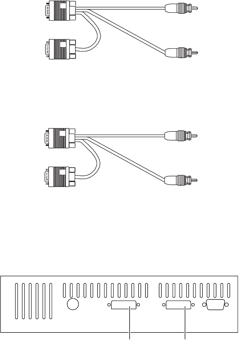
802BT/802R Video Test Generator User Guide 111
To monitor HDMI input:
• Use the VGA-to-RCA cable (part 30-00148) to connect the AV connector with a YPbPr
display, and the audio connections, as shown below.
A VGA-to-RCA (3) cable is available from Quantum Data (part 99-00503), which
requires a female-to-female HD15 adapter, which is also available from Quantum Data
(part 09-00251).
• Use the VGA-to-RCA cable (part 30-00148) to connect the AV connector with an
analog VGA display, and the audio connections as shown below.
DVI analyzer connections
The 802 generator with the DVI analyzer option is equipped with two digital DVI
connectors. In addition to a DVI Tx (output) connector that emulates a DVI transmit device,
a DVI Rx (input) connector is provided that allows a high-quality DVI display to be
emulated.
White
To audio source
To AV
connector
To audio player
Red
To VGA-to
RCA cable
White
To audio source
To AV
connector
To audio player
Red
To analog
display
VGARxTxSS
Transmitter Receiver
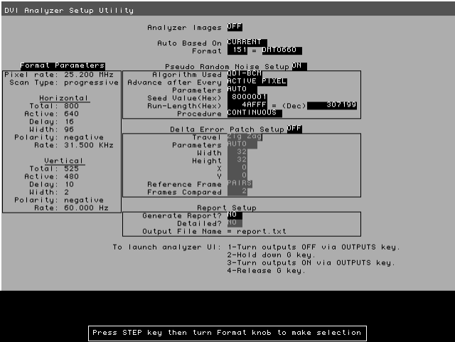
112 Chapter 8 Analyzing Digital Sources and Cables
Starting the Analyzer Setup Utility
Use the Analyzer Setup Utility to view or modify the configuration of the analyzer.
To start the Analyzer Setup Utility:
1. Start the generator in Digital-Friendly mode (see page 18).
2. Connect a digital display with the DVI or HDMI transmitter on the generator.
3. Select a format supported by the display (see “Selecting formats automatically” on
page 25).
4. Select the Analzyer image.
The Analyzer Setup Utility appears on the connected display.
Note: The Report Setup feature is not implemented.
Enabling and disabling analyzer images
Certain analyzer tasks require images to be displayed on an HDMI/DVI display.
To enable or disable display of analyzer images:
1. Start the Analyzer Setup Utility (see page 112).
2. Press and release the Step key.
The Step key illuminates and the Analyzer Images field is highlighted.
802BT/802R Video Test Generator User Guide 113
3. Using the Image knob, toggle between ON (to enable analyzer images) and OFF (to
disable analyzer images) setting.
4. Press and release the Step key to save the currently displayed parameters.
The light on the Step key extinguishes, and the new settings are implemented for
Analyzer mode operation.
Starting the analyzer
The analyzer functions as a special operating mode within the 802 generator. You must
place the generator into this mode to perform any analyzer tasks.
To put the generator in the analyzer mode:
1. Start the generator in Digital-Friendly mode (see page 18).
2. Press and release the Outputs key. The light on the key extinguishes.
3. While holding down the G key, press and release the Outputs key.
The Outputs key illuminates and the following message appears on the LCD. This
indicates that the generator is in analyzer mode (example shows DVI analyzer).
To take the generator out of the analyzer mode:
1. Press and release the Outputs key.
The generator is returned to the normal mode as a signal source. The LCD shows the
format and image currently active.
114 Chapter 8 Analyzing Digital Sources and Cables
Measuring timing of video signal
The analyzer provides the ability to analyze signal timing information of an external
HDMI/DVI source device. This feature allows you to test a transmitted HDMI/DVI signal for
anomalies and verify that the proper timing is output by the HDMI/DVI transmitter for a
given signal format.
The procedures below provide instructions for configuring the analyzer through the front
panel. Note that you can also measure timing with the analyzer through the command line.
For procedures using the command line refer to “Signal timing analysis commands” on
page 130.
The analyzer provides two measurement methods:
•Basic timing measurement – Displays limited measurements on LCD.
•Detailed timing measurement – Displays detailed measurements on a display
connected with the generator.
The procedures below provide instructions for configuring the analyzer through the front
panel. Note that you can also measure timing with the analyzer through the command line.
For procedures using the command line refer to “Signal timing analysis commands” on
page 130.
Setting up analyzer to measure timing
To operate the analyzer, you must select the desired HDMI/DVI signal source and set
signal format settings and parameters.
To set HDMI/DVI signal source parameters:
1. Start the Analyzer Setup Utility (see page 112).
2. Press and release the Step key.
The Step key illuminates and the Analyzer Images field is highlighted.
3. Using the Format knob, select the Auto Based On field.
4. If using the HDMI/DVI signal originating internally from the generator, follow these
steps:
a. Using the Image knob, select CURRENT in the highlighted field.
b. Using the Format knob, select the Format field.
c. Select the desired signal format number using the cursor (displayed under a digit
in the field) as follows:
• To move the cursor between digits, press the R and G keys.

802BT/802R Video Test Generator User Guide 115
• To select a number for a digit, turn the Image knob.
As the number in the Format field changes, the appropriate timing parameters for the
selection appear in the box under the Format Parameters field.
5. If using an HDMI/DVI signal originating externally from the generator, follow these
steps:
a. Select MEASURED in the highlighted field.
b. Select the Format Parameters field using the Format knob.
c. Capture the external signal’s timing parameters by pressing and releasing the B
key.
d. Configure the HDMI/DVI transmit device to output an HDMI/DVI signal.
After a few seconds, the external signal’s timing parameters are displayed in the box
under Format Parameters and in the Run Length(Hex) field.
Important: If the external source signal’s timing parameters change (or the field
selection is changed), the signal timing parameters must be recaptured.
6. Press and release the Step key to save the currently displayed parameters.
The light on the Step key extinguishes, and the new settings are implemented for
analyzer mode operation.
Measuring basic timing parameters
To view basic timing information of an external HDMI/DVI source signal:
1. Connect the HDMI/DVI transmit device to the HDMI/DVI Rx connector on the generator.
2. If necessary, set the proper HDMI/DVI signal source parameters within the generator.
•See “Starting the Analyzer Setup Utility” on page 112 for steps on viewing the
current analyzer configuration.
• To edit HDMI/DVI signal source parameters, see “Setting up analyzer to measure
timing” on page 114.
3. If desired, monitor the video signal received on the HDMI Rx connector (see page 110).
4. Start the analyzer (see “Starting the analyzer” on page 113).
5. Press and release the R key to display the horizontal and vertical frequencies of the
HDMI/DVI signal on the LCD (see example below).
HS rate VS rate
48076 72.188
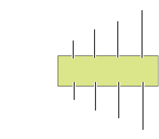
116 Chapter 8 Analyzing Digital Sources and Cables
6. Press the G key to display the following format parameters on the LCD.
Measuring detailed timing parameters
The analyzer can analyze detailed HDMI/DVI signal timing information. The timing
information is displayed on an HDMI/DVI display connected to the generator.
To view detailed timing information of an external HDMI/DVI source signal:
1. Connect the HDMI/DVI transmit device to the HDMI/DVI Rx connector on the generator.
2. Connect an HDMI/DVI display to the HDMI/DVI Tx connector on the generator.
3. If necessary, set the proper HDMI/DVI signal source parameters within the generator.
•See “Starting the Analyzer Setup Utility” on page 112 for steps on viewing the
current analyzer configuration.
• To edit HDMI/DVI signal source parameters, see “Setting up analyzer to measure
timing” on page 114.
4. If desired, monitor the video signal received on the HDMI Rx connector (see page 110).
5. Using the Format knob, select an appropriate format for the connected HDMI/DVI
display.
Note: To automatically configure the Format knob list based on the EDID structure of
a DDC-compliant display, hold down the R key, then press and release the ACS key.
1040 800 56 120
666 600 37 6
Horizontal period (pixels)
Vertical period (lines)
Active pixels per line
Active lines
Vertical pulse delay (pixels)
Horizontal pulse delay (pixels)
Horizontal pulse width (pixels)
Vertical pulse width (pixels)
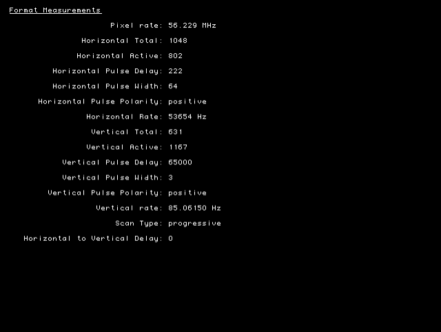
802BT/802R Video Test Generator User Guide 117
6. Using the Image knob, select the FormatRx image.
Detailed timing information of the HDMI/DVI signal is displayed on the HDMI/DVI
display (as shown in the example below).
118 Chapter 8 Analyzing Digital Sources and Cables
Testing cables and distribution systems
This section describes how to test HDMI or DVI cables, and distribution systems using
pseudo-random noise. Using different signal formats, the HDMI/DVI cable can be tested
over a wide range of frequencies.
The procedures below provide instructions for testing cable and distribution systems with
the analyzer through the front panel. Note that you can also perform these procedures
through the command line. For procedures using the command line refer to “Analyzing
pseudo-random noise in a cable or distribution system” on page 133.
To test a cable or distribution system:
1. Connect the HDMI/DVI cable to be tested between the HDMI/DVI Tx and Rx connectors
on the generator.
Note: If you are testing a fiber optic cable, plug the fiber optic cable connector marked
“transmitter” to the HDMI/DVI Tx connector on the generator, and plug the connector
marked “receiver” to the HDMI/DVI Rx connector on the generator. Use a 5 Vdc power
supply adapter at the receiver side of the cable.
2. If necessary, set the proper HDMI/DVI signal source and pseudo-random noise
parameters within the generator.
•See “Starting the Analyzer Setup Utility” on page 112 for steps on viewing the
current analyzer configuration.
• You will have to configure the analyzer for an internal source. To edit HDMI/DVI
signal source parameters, see “Setting up analyzer to measure timing” on page
114.
Note: The HDMI/DVI signal source must be set to internal (Auto Based On field set
to CURRENT) for this procedure.
• For information on what values to set the pseudo-random noise parameters as well
as instructions on how to set them, see “Setting pseudo-random noise parameters”
on page 142.
3. (HDMI only) If desired, monitor the video signal received on the HDMI Rx connector
(see “Monitoring HDMI analyzer signal input” on page 110).

802BT/802R Video Test Generator User Guide 119
4. Using the Format knob, select the signal format you want to use.
Any built-in formats may be used for this test. However, we recommend using several
formats spread over a wide range of frequencies. For example, the Test165 format is
commonly used to test at the maximum pixel frequency (165 MHz), while the DMT0660
format can be used to test at a very low frequency (25.175 MHz).Use the following
formats to test single-link DVI over a range of frequencies:
5. Start the analyzer (see “Starting the analyzer” on page 113).
Format Pixel rate (Mhz)
TEST165 165.000
DMT1660 162.000
DMT1285G 157.500
DMT1285A 148.500
DMT1648 135.000
DMT1275A 129.600
DMT1185 121.500
DMT1260G 108.000
DMT1085 94.500
DMT1170 94.200
DMT1075 78.750
DMT1070 75.000
720p60 74.250
DMT1060 65.000
DMT0885 56.250
DMT0872 50.000
DMT0875 49.500
DMT1043 44.900
DMT0860 40.000
DMT0685 36.000
DMT0785H 35.500
DMT0675 31.500
SMT0760V 28.322
DMT0660 25.175

120 Chapter 8 Analyzing Digital Sources and Cables
6. Press and release the B key to analyze the number of pixel errors detected per color
component of the received HDMI/DVI signal on the LCD (see example below).
To stop the analysis, press and release the B key again. The light on the key
extinguishes and the analysis stops.
7. Press and release the ACS key to analyze pixel error rate (in errors per billion) and
number of pixels measured (in billions) in the received HDMI/DVI signal on the LCD
(see example below).
Note: When the number of pixel errors becomes very large, the text “Very high” is
displayed in the bottom row of the LCD (replacing the numbers).
To stop the analysis, press and release the ACS key again. The light on the key
extinguishes and the analysis stops.
8. Press and release the DCS key to view the expected and measured values for the first
pixel error detected from the received HDMI/DVI signal (see example below).
To stop the analysis, press and release the DCS key again. The light on the key
extinguishes and the analysis stops.
9. To test the cable at a different frequency, return to step 4.
Testing accuracy of analyzer
You can verify the analyzer’s ability to correctly analyze pseudo-random noise.
The procedures below provide instructions for testing the accuracy of the analyzer through
the front panel. Note that you can also perform these procedures through the command
line. For procedures using the command line refer to “Testing the analyzer” on page 134.
To verify the analyzer’s pseudo-random noise analysis capability:
1. Connect the HDMI/DVI Tx connector to an HDMI/DVI display.
2. Using the Format knob, select an appropriate format for the connected HDMI/DVI
display.
R: G: B:
0 21 0
PER: pels/billion
4.255 0.88
original: 40018C
1st error: FFFFFF

802BT/802R Video Test Generator User Guide 121
Note: To automatically configure the Format knob list based on the EDID structure of
a DDC-compliant display, hold down the R key, and then press and release the ACS
key.
3. If necessary, set the proper HDMI/DVI signal source parameters within the generator.
•See “Starting the Analyzer Setup Utility” on page 112 for steps on viewing the
current analyzer configuration.
• You will have to configure the analyzer for an internal source. To edit HDMI/DVI
signal source parameters, see “Setting up analyzer to measure timing” on page
114.
4. Configure pseudo-random noise parameters to implement a single pseudo-random
noise test sequence. This requires setting the Procedure field to SINGLE SHOT.
• To edit pseudo-random noise parameters, see “Setting pseudo-random noise
parameters” on page 142.
5. Disconnect the HDMI/DVI Tx connector from the HDMI/DVI display.
6. Connect an HDMI/DVI cable between the HDMI/DVI Tx and Rx connectors on the
generator.
7. Using the Format knob, select the signal format you want to use.
• Any of the pre-defined formats can be used for this test for DVI. However, we
recommend using the Test165 format to test DVI at the maximum pixel frequency
(165MHz). For HDMI the Test81 format should be used.
Note: In order to access the test formats such as Test165, you may have to re-invoke
the default format list by applying pressing and holding the R key and then pressing and
releasing the ACS key.
8. Using the Image knob, select either the PRN_5 or PRN_9 image.
9. Start the analyzer (see “Starting the analyzer” on page 113).
10. Press and release the B key to analyze number of pixel errors detected per color
component of the received HDMI/DVI signal on the LCD (see example below).
• If you selected the PRN_5 image, the following should be displayed (5 errors in
each color component).
• If you selected the PRN_9 image, the following should be displayed (9 errors in
each color component).
R: G: B:
5 5 5
R: G: B:
9 9 9
122 Chapter 8 Analyzing Digital Sources and Cables
11. To verify accuracy using a different frequency, halt the analyzer mode and return to step
7.
802BT/802R Video Test Generator User Guide 123
Measuring pixel errors
In cases where the external HDMI/DVI device cannot generate pseudo-random noise, a
“delta error” testing capability is provided that allows analysis for flickering pixels in a
still-frame test image. With the video signal connected to the analyzer input, signal quality
can be measured blindly and test results delivered in simple numeric terms.
The procedures below provide instructions through the front panel. Note that you can also
configure the analyzer to measure pixel errors through the command line. For procedures
using the command line refer to “Pseudo-random noise generation commands” on page
132.
Setting delta error patch parameters
To enable and configure delta error patch testing by the analyzer, you must set certain
analyzer parameters properly. Use the procedure to configure the analyzer to test for delta
error patch testing.
To set delta error patch testing parameters:
1. Start the Analyzer Setup Utility (see page 112).
2. If necessary, see “Setting up analyzer to measure timing” on page 114 for steps to
configure the appropriate HDMI/DVI signal source and timing parameters.
3. Press and release the Step key.
The Step key illuminates and the Analyzer Images field is highlighted.
4. Using the Format knob, select the Delta Error Patch Setup field.
5. Using the Image knob, specify whether to enable (ON) or disable (OFF) delta error
patch.
If set to OFF, delta error patch is disabled and all associated fields are disabled.
6. Using the Format knob, select the Travel field.
7. Using the Image knob, specify how you want the patch to move across the display as
follows:
• Select Zig Zag to move over the active video in a zig zag fashion.
• Select FIXED to move over the active video in a fixed position.
8. Using the Format knob, select the Parameters field.
9. Using the Image knob, specify how you want the delta error patch implemented as
follows:
• Select AUTO to allow the generator to automatically set the patch settings. The
patch width and height are calculated based on size of the active video area.
124 Chapter 8 Analyzing Digital Sources and Cables
• Select MANUAL to define specific patch settings.
10. To define specific settings for delta error patch (width, height, and position), follow these
steps:
a. Using the Format knob, select the Width, Height, X, or Y field.
Note: If you selected AUTO in the Parameters field and the HDMI/DVI signal source is
internal (Auto Based On field set to CURRENT), the Width and Height fields are not
selectable. Similarly, if you selected AUTO in the Parameters field and the HDMI/DVI
signal source is external (Auto Based On field set to MEASURE), the Width and Height
fields are set when measuring the external signal’s timing parameters (see “Setting up
analyzer to measure timing” on page 114).
b. Set the parameter (in decimal) using the cursor (displayed under a digit in the field)
to select the appropriate value as follows:
• To move the cursor between digits, press the R and G keys.
• To select a number for a digit, turn the Image knob.
c. Repeat these steps until each parameter is defined.
11. Using the Format knob, select the Reference Frame field.
12. Using the Image knob, specify the method used to compare the patch within different
frames as follows:
• Select FIRST to use the first field as the reference for comparison with other
patches in other frames.
• Select PAIRS to set the comparison to be performed in each two successive
frames.
13. Using the Format knob, select the Frames Compared field.
14. Specify the number of frames to be compared with the patch dimensions using the
cursor (displayed under a digit in the field) to select the appropriate value as follows:
• To move the cursor between digits, press the R and G keys.
• To select a number for a digit, turn the Image knob.
15. Press and release the Step key to save the currently displayed parameters.
The light on the Step key extinguishes, and the settings are implemented for Analyzer
mode operation.
802BT/802R Video Test Generator User Guide 125
Measuring pixel errors in patch
The analyzer can test and analyze the transmission quality of an external HDMI/DVI
transmit device using a delta error patch pattern. The analyzer captures all or a portion of
an external image (patch pattern) and verifies that all pixels match over a number of
frames. The results are output to an HDMI/DVI display using a special image.
To test an external HDMI/DVI signal using delta error patch pattern:
1. Connect the HDMI/DVI transmit device to the HDMI/DVI Rx connector on the generator.
2. Connect an HDMI/DVI display to the HDMI/DVI Tx connector on the generator.
3. If necessary, set the proper HDMI/DVI signal source and delta error patch parameters
within the generator.
•See “Starting the Analyzer Setup Utility” on page 112 for steps on viewing the
current analyzer configuration.
• To edit HDMI/DVI signal source parameters, see “Setting up analyzer to measure
timing” on page 114.
• To edit delta error patch parameters, see “Setting delta error patch parameters” on
page 123.
4. (HDMI only) If desired, monitor the video signal received on the HDMI Rx connector
(see “Monitoring HDMI analyzer signal input” on page 110).
5. Generate a static image from the HDMI/DVI transmit device.
6. Using the Format knob, select an appropriate format for the connected HDMI/DVI
display.
Note: To automatically configure the Format knob list based on the EDID structure of
a DDC-compliant display, hold down the R key, then press and release the ACS key.
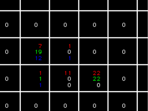
126 Chapter 8 Analyzing Digital Sources and Cables
7. Using the Image knob, select the DeltaErr image.
The DeltaErr image appears on the connected HDMI/DVI display. As shown in the
example below, errors are presented in the area in which they are found by color
component.
802BT/802R Video Test Generator User Guide 127
Testing InfoFrames (HDMI only)
The HDMI analyzer can analyze InfoFrame data from an incoming HDMI signal. With this
capability, an HDMI transmit device can be tested for its ability to transmit InfoFrame
packets correctly.
Testing HDMI transmit device InfoFrame capability
The 802 generator can monitor the InfoFrame content of the received HDMI signal.
To view current HDMI InfoFrame contents received from an HDMI transmitter:
1. Connect an HDMIdisplay to the HDMI Tx connector on the generator.
2. Connect the HDMI source to the HDMI Rx connector on the generator.
3. Setup the generator for HDMI output (see page 147).
4. If desired, monitor the video signal received on the HDMI Rx connector (see
“Monitoring HDMI analyzer signal input” on page 110).
5. Using the Format knob, select an appropriate format for the connected HDMI/DVI
display.
Note: To automatically configure the Format knob list based on the EDID structure of
a DDC-compliant display, hold down the R key, then press and release the ACS key.
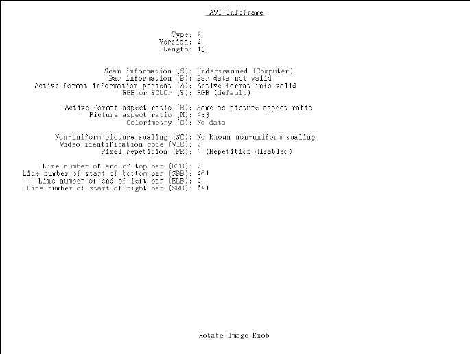
128 Chapter 8 Analyzing Digital Sources and Cables
6. Using the Image knob, select the PacketRx image.
The PacketRx image appears on the connected HDMI display. Shown in the image are
the current settings for the AVI InfoFrame input.
7. Press and release the Step key.
The Step key illuminates.
8. Using the Image knob, select the appropriate InfoFrame type.
The contents of the appropriate InfoFrame input are displayed on the HDMI display.
9. When finished, press and release the Step key.
The light on the Step key extinguishes.
802BT/802R Video Test Generator User Guide 129
Testing audio (HDMI only)
The HDMI analyzer can process audio data from an incoming HDMI signal. With this
capability, an HDMI source can be tested for its ability to successfully transmit audio
packets.
Testing HDMI transmit device audio capability
The 802 generator can monitor the audio content of the received HDMI signal.
To monitor audio content received from an HDMI transmitter:
1. Connect the HDMI transmit device to the HDMI Rx connector on the generator.
2. If necessary, set up the generator for HDMI output (see “Setting up the generator for
HDMI operation” on page 147).
3. Monitor the audio signal received on the HDMI Rx connector using an external audio
device (see “Monitoring HDMI analyzer signal input” on page 110.
130 Chapter 8 Analyzing Digital Sources and Cables
Controlling analyzer using command-line interface
You can operate the Analyzer using the 802 generator’s command line interface. This
section describes Analyzer functions and commands and provides examples of command
sequences you can use to perform Analyzer tasks.
For command descriptions, see Appendix A, “Command Reference.”
Signal timing analysis commands
This section provides command line procedures for viewing signal timing parameters.
Viewing signal timing parameters (on an HDMI/DVI monitor)
This example displays timing and allows you to view real-time, detailed HDMI/DVI signal
timing information from a connected HDMI/DVI transmit device.
To view basic timing information of an external HDMI/DVI source signal:
1. Connect the HDMI/DVI transmit device to the HDMI/DVI Rx connector on the generator.
2. If desired, monitor the video signal received on the HDMI/DVI Rx connector (see page
110).
3. Using a terminal emulator, establish a terminal connection with the generator. Refer to
“Setting up a terminal connection with the generator” on page 14.
4. Enter the following commands to configure the generator to output a digital signal
(HDMI or DVI):
SROP 2 4
This removes analog friendly mode and configures the generator to output either a DVI
or HDMI signal depending on the interface hardware the generator is equipped with
(DVI or HDMI).
5. (optional) Enter the following command to set the status display mode:
SROP 8
6. Enter the following commands to initiate the measurement of timing parameters.
ANIG 1 // enables analyzer images to be displayed
IMGL FormatRx // loads the FormatRX image into the edit buffer
IMGU // applies the FormatRX image to the generator/analyzer
Viewing specific timing parameters
The following is an example of using commands to view the total number of horizontal
pixels and horizontal frequency of the HDMI/DVI signal.
802BT/802R Video Test Generator User Guide 131
To view specific timing information of an external HDMI/DVI source signal:
1. Connect the HDMI/DVI transmit device to the HDMI/DVI Rx connector on the generator.
2. Using a terminal emulator, establish a terminal connection with the generator. Refer to
“Setting up a terminal connection with the generator” on page 14.
3. Enter the following commands to configure the generator to output a digital signal
(HDMI or DVI):
SROP 2 4
This removes analog friendly mode and configures the generator to output either a DVI
or HDMI signal depending on the interface hardware the generator is equipped with
(DVI or HDMI).
4. (optional) Enter the following command to set the status display mode:
SROP 8
5. Enter the following commands to initiate the measurement of timing parameters.
PNSF 1 // selects the source of timing information as “Measured”
TMAU // initiates measurement of timing from external source
HTOT? // queries for the horizontal total pixels
HRES? // queries for the horizontal active pixels
See page 548 for additional parameters you can query.
132 Chapter 8 Analyzing Digital Sources and Cables
Pseudo-random noise generation commands
This section provides command line procedures for generating pseudo-random noise.
Generating pseudo-random noise
The following is an example of using commands to first configure and then generate
pseudo-random noise.
To generate pseudo-random noise:
1. Using a terminal emulator, establish a terminal connection with the generator. Refer to
“Setting up a terminal connection with the generator” on page 14.
2. Enter the following commands to configure the generator to output a digital signal
(HDMI or DVI):
SROP 2 4
This removes analog friendly mode and configures the generator to output either a DVI
or HDMI signal depending on the interface hardware the generator is equipped with
(DVI or HDMI).
3. (optional) Enter the following command to set the status display mode:
SROP 8
4. Enter the following commands to generate pseudo-random noise.
PNSF 0 // selects internal timing source for pseudo-random noise
PNST 1 // specifies QDI-BCM algorithm
PNSA 1 // sets pseudo random noise to be calculated each pixel clock
PNSM 0 // sets pseudo random noise test to run in auto mode
PNSP 0 // sets procedure for pseudo-random noise test to “continuous”
PNSG 1 // enables the pseudo-random noise test
PNGU // turns on the pseudo-random noise test
<CR> // a carriage return halts the continuous test
5. Enter the following commands to stop pseudo-random noise generation.
PNSG 0
PNGU
Pseudo-random noise analysis commands
This section provides command line procedures for generating pseudo-random noise and
analyzing the received data.
802BT/802R Video Test Generator User Guide 133
Analyzing pseudo-random noise in a cable or distribution
system
The following example uses commands to test a connected HDMI/DVI cable or distribution
system.
To analyze pseudo-random noise in a cable or distribution system:
1. Connect the DVI or HDMI cable between the transmit and receive connectors on the
generator.
If you are testing a distribution system connect an access cable to the distribution
center to the transmit connector on the generator and a second access cable to the
receive connector on the generator.
2. Using a terminal emulator, establish a terminal connection with the generator. Refer to
“Setting up a terminal connection with the generator” on page 14.
3. Enter the following commands to configure the generator to output a digital signal
(HDMI or DVI):
SROP 2 4
This removes analog friendly mode and configures the generator to output either a DVI
or HDMI signal depending on the interface hardware the generator is equipped with
(DVI or HDMI).
4. (optional) Enter the following commands to set the status display mode:
SROP 8
5. Enter the following commands to analyze pseudo-random noise in a cable or
distribution system.
FMTL TEST165 // loads the TEST165 format for testing DVI
Note: For HDMI testing load the TEST81 format.
FMTU // applies the TEST165 or TEST81 format to the generator
6. Enter the following commands to configure the pseudo-random noise parameters.
PNSF 0 // selects internal timing source for pseudo-random noise
PNST 1 // specifies QDI-BCM algorithm
PNSA 1 // sets pseudo random noise to be calculated each pixel
PNSM 0 // sets pseudo random noise test to run in auto mode
PNSP 100 // sets pseudo-random noise for 100 “multi-shots”
PNAU // loads the generator with pseudo-random noise settings
Note: The test will stop automatically if configured to run in the single or multi-shot
mode. If you initiate the test in the continuous mode, you will have to enter a carriage
return to halt the test after PNAU is invoked.
7. Enter the following commands to view the results of the test.
134 Chapter 8 Analyzing Digital Sources and Cables
GPER? // returns the pixel error rate in errors per billion
GNPT? // returns the number of pixels measured in billions
GCET? // returns the number of bad pixels for R, G, B components
GFED? // returns information about the first error encountered
Analyzing pseudo-random noise from an external source
The following example tests an HDMI/DVI transmit device’s pixel data using
pseudo-random noise generated by an external source.
To analyze pseudo-random noise from an external source:
1. Connect the DVI or HDMI cable between the receive connector on the generator and
the output interface on the device under test.
2. Using a terminal emulator, establish a terminal connection with the generator. Refer to
“Setting up a terminal connection with the generator” on page 14.
3. Enter the following commands to configure the generator to output a digital signal
(HDMI or DVI):
SROP 2 4
This removes analog friendly mode and configures the generator to output either a DVI
or HDMI signal depending on the interface hardware the generator is equipped with
(DVI or HDMI).
4. (optional) Enter the following commands to set the status display mode:
SROP 8
5. Enter the following commands to configure the pseudo-random noise parameters.
PNSF 1 // selects external timing source for pseudo-random noise
PNST 1 // specifies QDI-BCM algorithm
TMAU // initiates measurement of timing from external source
PNSA 1 // sets pseudo random noise to be calculated each pixel
PNSM 0 // sets pseudo random noise test to run in auto mode
PNSP 100 // sets pseudo-random noise for 100 “multi-shots”
PNAU // loads the generator with the pseudo-random noise settings
Note: The test will stop automatically if configured to run in the single or multi-shot
mode. If you initiate the test in the continuous mode, you will have to enter a carriage
return to halt the test after PNAU is invoked.
6. Enter the following commands to view the results of the test.
GPER? // returns the pixel error rate in errors per billion
GNPT? // returns the number of pixels measured in billions
GCET? // returns the number of bad pixels for R, G, B components
GFED? // returns information about the first error encountered
Testing the analyzer
The following example verifies the analyzer’s pseudo-random noise analysis capability.
802BT/802R Video Test Generator User Guide 135
To verify the analyzer’s pseudo-random noise analysis capability:
1. Using a terminal emulator, establish a terminal connection with the generator. Refer to
“Setting up a terminal connection with the generator” on page 14.
2. Enter the following commands to configure the generator to output a digital signal
(HDMI or DVI):
SROP 2 4
This removes analog friendly mode and configures the generator to output either a DVI
or HDMI signal depending on the interface hardware the generator is equipped with
(DVI or HDMI).
3. (optional) Enter the following commands to set the status display mode:
SROP 8
4. Connect an HDMI/DVI cable between the HDMI/DVI Tx and Rx connectors on the
generator.
5. Enter the following commands to select the signal format and image.
FMTL TEST165 // loads the TEST165 format
Note: For HDMI testing load the TEST81 format.
FMTU // applies the TEST165 or TEST81 format to the generator
IMGL PRN_9 // loads the PRN_9 image
IMGU // activates the image in the generator
6. Enter the following commands to set the pseudo-random noise parameters.
PNSF 0 // selects internal timing source for pseudo-random noise
PNST 1 // specifies QDI-BCM algorithm
PNSA 1 // sets pseudo random noise to be calculated each pixel
PNSM 0 // sets pseudo-random noise test to “single-shot”
PNAU // loads the generator with pseudo-random noise settings
Note: The test will stop automatically if configured to run in the single or multi-shot
mode. If you initiate the test in the continuous mode, you will have to enter a carriage
return to halt the test after PNAU is invoked.
7. Enter the following commands to view the results of the test.
GPER? // returns the pixel error rate in errors per billion
GNPT? // returns the number of pixels measured in billions
GCET? // returns the number of bad pixels for R, G, B components
GFED? // returns information about the first error encountered
Analyzing pixel data (delta error patch)
The following is an example of using commands to test an HDMI/DVI transmit device’s
pixel data using a delta error patch test.
136 Chapter 8 Analyzing Digital Sources and Cables
To set delta error patch testing parameters:
1. Using a terminal emulator, establish a terminal connection with the generator. Refer to
“Setting up a terminal connection with the generator” on page 14.
2. Enter the following commands to configure the generator to output a digital signal
(HDMI or DVI):
SROP 2 4
This removes analog friendly mode and configures the generator to output either a DVI
or HDMI signal depending on the interface hardware the generator is equipped with
(DVI or HDMI).
3. (optional) Enter the following commands to set the status display mode:
SROP 8
4. Connect the HDMI/DVI transmit device to the HDMI/DVI Rx connector on the generator.
5. Connect an HDMI/DVI display to the HDMI/DVI Tx connector on the generator.
6. Enter the following commands to load a suitable format for the display under test.
FMTL DMT0660 // loads the DMT0660 format for testing
FMTU // applies the DMT0660 format to the generator
7. Enter the following commands to load a suitable static image.
IMGL FLAT // loads the static image for testing
IMGU // applies the image to the generator
8. Enter the following commands to configure the delta patch parameters.
9.
PDSX 128 // sets patch starting at x-pixel 128
PDSY 256 // sets patch starting at y-pixel 256
PDSH 64 // sets patch height at 64 pixel
PDSW 96 // sets patch width at 90 pixels
10. Enter the following commands to run the delta patch test.
PDAU // captures patch of image
ANIG 1 // enables analyzer images
IMGL DeltaErr // loads the DeltaErr image
IMGU // activates the image in the generator
802BT/802R Video Test Generator User Guide 137
Generating pseudo-random noise from your device
This section explains how to implement pseudo-random noise is your own device.
Implementing pseudo-random noise from your device
The analyzer can test and analyze pixel data received from an HDMI/DVI source. To
accomplish this, a pseudo-random noise pattern is used that provides a sequence of
highly dynamic pixel values.
To maximize your ability to analyze pixel data generated by set-top boxes, you must be
able to generate pseudo-random noise. To facilitate this, you can use the lfsr.h and lfsl.cpp
source code files from
http://www.quantumdata.com/support/resources/pr_noise/QDI-BCM_PseudoNoise.ZIP,
which enable you to generate QDI-BCM pseudo-random noise from your device.
Once implemented, you can verify that the code is implemented correctly by using the
Dump10K() function to write the first 10,000 pixel values to a file. This result should match
the contents of the PN_31_24.txt reference file included in
http://www.quantumdata.com/support/resources/pr_noise/QDI-BCM_PseudoNoise.ZIP.
lfsr.h
The following source code is provided for the lfdr.h file.
// LFSR.h: interface for the CLFSR class.
#if !defined(AFX_LFSR_H__5947F6F9_1DBE_4E6E_9AFB_77D5D8857A10__INCLUDED_)
#define AFX_LFSR_H__5947F6F9_1DBE_4E6E_9AFB_77D5D8857A10__INCLUDED_
#if _MSC_VER > 1000
#pragma once
#endif // _MSC_VER > 1000
class CLFSR
{
public:
void Dump10K();
unsigned long GetPixel();
void Reset();
CLFSR();
virtual ~CLFSR();
protected:
int state;
unsigned long seed;
};
138 Chapter 8 Analyzing Digital Sources and Cables
#endif //
!defined(AFX_LFSR_H__5947F6F9_1DBE_4E6E_9AFB_77D5D8857A10__INCLUDED_)
lfsl.cpp
The following source code is provided for the tfsl.cpp file.
// Implementation of the CLFSR class
#include “LFSR.h”
#include <stdio.h>
#ifdef _DEBUG
#undef THIS_FILE
static char THIS_FILE[]=__FILE__;
#define new DEBUG_NEW
#endif
// enable this to light up pixels 1,2,3 as red,green,blue
// in horizontal order
// Pixel 1 represents the top left corner of the screen
// when this is enabled, all other pixels are black
//#define RGB_TEST
// Construction/Destruction
unsigned long pixelvalue;
CLFSR::CLFSR()
{
}
CLFSR::~CLFSR()
{
}
void CLFSR::Reset()
{
state=0;
seed=0x08000001;
}
// Pixel 1 should be 0x000000
// Pixel 2 should be 0x00 (7-bits) , Opcode(10-bits), SeedHigh(7 bits)
// Pixel 3 should be SeedLow (24 bits)
// All other pixels are then set based on the results of the LFSR
calculations.
// The 10-bit Opcode is custom per Quantum Data’s request and it will be
set to ‘00,0000,0111’.
unsigned long CLFSR::GetPixel()
{
unsigned long temp;
802BT/802R Video Test Generator User Guide 139
// states 0 to 2 are specific for QuantumData
switch (state)
{
// pixel 1
case 0:
pixelvalue=seed;
state++;
#ifdef RGB_TEST
return (0xff0000); // red
#else
return(0);
#endif
break;
// pixel 2
case 1:
temp=((0x007<<7) | (( seed &0x7f000000)>>24)) & 0xffffff;
state++;
#ifdef RGB_TEST
return (0x00ff00); // green
#else
return(temp);
#endif
break;
// pixel 3
case 2:
temp=seed &0x00ffffff;
state++;
#ifdef RGB_TEST
return (0x0000ff); // blue
#else
return(temp);
#endif
break;
default:
pixelvalue= ((pixelvalue & 0x7f)<<24) | ( ((pixelvalue>>4)
& 0xffffff) ^ ((pixelvalue>>7) & 0xffffff) );
#ifdef RGB_TEST
return (0x0); // blank
#else
return(pixelvalue & 0xffffff);
#endif
break;
break;
}

140 Chapter 8 Analyzing Digital Sources and Cables
}
void CLFSR::Dump10K()
{
int i;
FILE* f;
char s[100];
f=fopen(“c:\\temp\\noise.txt”,”w”);
Reset();
for (i=0;i<10000;i++)
{
sprintf(s,”%.6lx”,GetPixel());
fprintf(f,”%s\r\n”,s);
}
// AfxMessageBox(“See c:\\temp\\noise.txt”);
fclose(f);
Sending pseudo-random noise to external device
The analyzer can be the source for a pseudo-random noise test pattern. HDMI/DVI
displays can use this test pattern for testing and analysis purposes.
To generate a pseudo-random noise test pattern:
1. Connect the HDMI/DVI receiver device to the HDMI/DVI Tx connector on the generator.
2. If necessary, set the proper pseudo-random noise parameters within the generator.
•See “Starting the Analyzer Setup Utility” on page 112 for steps on viewing the
current analyzer configuration.
• To edit pseudo-random noise parameters, see “Setting pseudo-random noise
parameters” on page 142.
3. Place the generator in HDMI/DVI analyzer mode.
•See “Starting the analyzer” on page 113 for steps on launching analyzer mode.
4. Press and release the Step key to generate pseudo-random noise to be transmitted.
The key illuminates and pseudo-random noise is transmitted from the HDMI/DVI Tx
connector. The following message appears on the LCD:
5. To stop pseudo-random noise generation, press and release the Step key.
The light on the key extinguishes and pseudo-random noise is no longer transmitted.
Generating Psudo
Random Noise

802BT/802R Video Test Generator User Guide 141
Analyzing noise from an external device
The analyzer can test and analyze the transmission quality of an external HDMI/DVI
transmit device using pseudo-random noise.
Important: To perform this test, the external HDMI/DVI transmit device must be able to
generate pseudo-random noise using the QDI-BCM format.
Note: Before performing this test, you may first want to test the cables and distribution
equipment used to transport the HDMI/DVI signal between the external device and
generator. For more information, see “Testing cables and distribution systems” on page
118.
To test an external HDMI/DVI signal using pseudo-random noise:
1. Connect the HDMI/DVI transmit device to the HDMI/DVI Rx connector on the generator.
2. If necessary, set the proper HDMI/DVI signal source and pseudo-random noise
parameters within the generator.
•See “Starting the Analyzer Setup Utility” on page 112 for steps on viewing the
current analyzer configuration.
• To edit HDMI/DVI signal source parameters, see “Setting up analyzer to measure
timing” on page 114.
Note: The HDMI/DVI signal source must be set to external (Auto Based On field set
to MEASURED) for this procedure.
• To edit pseudo-random noise parameters, see “Setting pseudo-random noise
parameters” on page 142.
3. If desired, monitor the video/audio signal received on the HDMI Rx connector (see
“Monitoring HDMI analyzer signal input” on page 110).
4. Start the analyzer (see page 113).
5. Generate pseudo-random noise from the HDMI/DVI transmit device.
6. Press and release the B key to analyze the number of pixel errors detected per color
component of the received HDMI/DVI signal (see example below).
To stop the analysis, press and release the B key again. The light on the key
extinguishes and the analysis stops.
R: G: B:
0 21 0

142 Chapter 8 Analyzing Digital Sources and Cables
7. Press and release the ACS key to analyze pixel error rate (in errors per billion) and
number of pixels measured (in billions) in the received HDMI/DVI signal on the LCD
(see example below).
Note: When the number of pixel errors becomes very large, the text “Very high” is
displayed in the bottom row of the LCD (replacing the numbers).
To stop the analysis, press and release the ACS key again. The light on the key
extinguishes and the analysis stops.
8. Press and release the DCS key to analyze the expected and reported values for the
first pixel error detected from the received HDMI/DVI signal on the LCD (see example
below).
To stop the analysis, press and release the DCS key again. The light on the key
extinguishes and the analysis stops.
Setting pseudo-random noise parameters
This section describes how to modify the pseudo-random noise output by the generator.
To set pseudo-random noise parameters:
1. Start the Analyzer Setup Utility (see “Starting the Analyzer Setup Utility” on page 112).
2. If necessary, see “Setting up analyzer to measure timing” on page 114 for steps to
configure the appropriate HDMI/DVI signal source and timing parameters.
3. Press and release the Step key.
The Step key illuminates and the Analyzer Images field is highlighted.
4. Using the Format knob, select the Pseudo Random Noise Setup field.
5. Using the Image knob, specify whether to enable (ON) or disable (OFF)
pseudo-random noise.
If set to OFF, pseudo-random noise is disabled and all associated fields are disabled.
6. Using the Format knob, select the Advance after Every field.
7. Using the Image knob, specify how you want pseudo-random noise generated, as
follows:
PER: pels/billion
4.255 0.88
original: 40018C
1st error: FFFFFF
802BT/802R Video Test Generator User Guide 143
• Select PIXEL to generate and receive pseudo-random noise at every pixel within
the whole frame.
• Select ACTIVE PIXEL to generate and receive pseudo-random noise only at active
pixels within the frame.
8. Using the Format knob, select the Parameters field.
9. Using the Image knob, specify how you want the pseudo-random noise seed and
sequence length implemented, as follows:
• Select AUTO to use the default seed value and sequence length. The default
settings ensure a stable, pseudo-random noise image. If you select this setting,
proceed to step 11.
• Select MANUAL to define specific seed value and sequence length settings. If you
select this setting, proceed to step 10.
Note: If the HDMI/DVI signal source is external (Auto Based On field set to
MEASURED), you cannot manually define these settings. The Parameters and Seed
Value(Hex) fields appear dimmed, and the Run Length(Hex) field is set when
measuring the external signal’s timing parameters (see “Setting up analyzer to
measure timing” on page 114).
10. If you set the Parameters field to MANUAL, define specific settings for pseudo-random
noise seed and sequence length by following these steps:
a. Using the Format knob, select the Seed Value(Hex) field.
b. Specify the desired seed value using the cursor (displayed under a digit in the field)
to select the appropriate value as follows:
• To move the cursor between digits, press the R and G keys.
• To select a number for a digit, turn the Image knob.
c. Using the Format knob, select either the Run-Length(Hex) or Run-Length(Dec)
field.
d. Specify the desired sequence length value in hexidecimal (if Run-Length(Hex)
field is highlighted) or decimal (if Run-Length(Dec) field is highlighted) using the
cursor (displayed under a digit in the field) to select the appropriate value as
follows:
• To move the cursor between digits, use the R and G keys.
• To select a number for a digit, use the Image knob.
11. Using the Format knob, select the Procedure field.
12. Using the Image knob, select the sequence type for pseudo-random noise to be
generated and tested as follows:
• Select CONTINUOUS to run the pseudo-random noise sequence continuously.
• Select SINGLE SHOT to run one sequence of pseudo-random noise.
144 Chapter 8 Analyzing Digital Sources and Cables
• Select MULTI SHOT to define a specific number of sequences to run. Define the
number of sequences to run in the field next to the Procedure field.
13. Press and release the Step key to save the currently displayed parameters.
The light on the Step key extinguishes, and the settings are implemented for analyzer
mode operation.
146 Chapter 9 Testing HDMI Sink Devices
Overview
The HDMI option enables the generator to test HDMI-compliant sink devices. With the
HDMI option, the generator outputs HDMI-compatible TMDS video and data packets
containing audio and auxiliary information.
The HDMI option includes the following features:
• Advanced E-EDID parsing
• Generation of all EIA/CEA-861-B formats below 165 MHz (with all possible variations)
• Pixel repetition test capabilities
• Internal sine wave generator and external SPDIF audio input for audio testing
• AFD test capabilities
• Automatic and manual InfoFrame configuration
Note: This chapter refers to the EIA/CEA-861B standard, which may be purchased from
http://global.ihs.com/
For HDMI compliance testing procedures, see “Testing EDID in HDMI sink device for
HDMI compliance” on page 173.
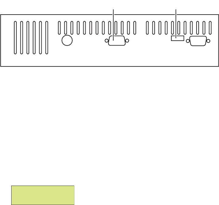
802BT/802R Video Test Generator User Guide 147
Getting started
This section provides basic information on how to operate the 802 generator using the
HDMI option.
HDMI connections
The generator with the HDMI option has two connectors. In addition to an HDMI Tx
(output) connector that emulates an HDMI source device, an AV connector allows external
SPDIF audio to be input to the HDMI signal. To use the AV port, an RCA-to-VGA cable is
included with the generator.
The following figure shows the location of these connectors on a model 802 generator with
the HDMI option.
Setting up the generator for HDMI operation
To perform testing using the HDMI option, you must ensure that the generator is
configured to output HDMI signals:
To set up the generator to perform HDMI testing:
1. Hold down the G and B keys, and then power on the generator.
The following message appears on the front panel LCD.
2. Release the G and B keys.
The generator is placed in Digital Friendly mode.
SS AVTx VGA
HDMI transmitterAudio/Video connector
Special: keys
Digital friendly

148 Chapter 9 Testing HDMI Sink Devices
3. Hold down the R and ACS keys, and then cycle the power to the generator.
The following message appears on the front panel LCD.
4. Release the R and ACS keys.
The generator is placed in Hot-Plug Format mode. This loads the Format knob list with
formats supported by the connected HDMI display (hot-plug formats read via EDID
structure of attached display).
Note: To toggle between the factory default and hot-plug Format knob lists, press and
release the R and ACS keys. Using the factory default Format knob list will disable the
generator’s ability to automatically select the appropriate output signal protocol (HDMI
or DVI) as performed in step 6. In this case, you must manually select the proper TMDS
output signal via Toggle DVI/HDMI key operation (R and G keys).
5. Hold down the Step, G, and B keys while starting the genertor, until Status display
appears on the LCD.
6. Release the Step, G, and B keys to enable status display on the generator (see
example below).
The format status on the LCD will indicate whether the unit is outputting HDMI or DVI
signal protocol from the Tx connector. An “H” in the format status (H8C in the example
above) indicates HDMI output; a “D” in the format status indicates DVI output.
Note: With the compliant Hot-plug Formats mode active and a hot-plug detected, the
generator automatically selects the appropriate TMDS output signal protocol (HDMI or
DVI) for the attached display (via EDID read).
7. If the output signal protocol is DVI, toggle to HDMI protocol by holding down the R key,
then pressing and releasing the G key.
The format status changes to “H” (from “D”) on the LCD.
Special: keys
hot-plug formats
H31 D8C=DMT0659
V60 0=SMPTE133
Video type Format name
Image name
Color depth
Color space
Image version

802BT/802R Video Test Generator User Guide 149
Testing HDMI video
This section provides steps on how to test handling of HDMI video signals by an HDMI
display. To support HDMI, the generator provides pre-defined formats for every video
format specified in the EIA/CEA-861-B standard. These pre-defined formats support all
aspects of the HDMI signal (video, audio, and auxiliary data).
The following table lists the generator formats used to test support for HDMI
(EIA/CEA-861-B) formats.
EIA/CEA-861-B Video
Identification Code Quantum Data format
1 DMT0659, DMT0660
2 480p59, 480p60, 480p59LH, 480p60LH
3 480p59SH, 480p60SH
4 720p59, 720p60
5 1080i29, 1080i30
6 480i2x29, 480i2x30, 480i2xL1, 480i2xL2
7 480i2xS1, 480i2xS2
8 240p2x_1, 240p2x_2, 240p2x_3, 240p2x_4,
240p2xL1, 240p2xL2, 240p2xL3, 240p2xL4
9 240p2xS1, 240p2xS4, 240p2xS3, 240p2xS4
10 480i4x29, 480i4x30, 480i4xL1, 480i4xL2
11 480i4xS1, 480i4xS2
12 240p4x_1, 240p4x_2, 240p4x_3, 240p4x_4,
240p4xL1, 240p4xL2, 240p4xL3, 240p4xL4
13 240p4xS1, 240p4xS2, 240p4xS3, 240p4xS4
14 480p2x59, 480p2x60, 480p2xL1, 480p2xL2
15 480p2xS1, 480p2xS2
16 1080p59, 1080p60
17 576p50, 576p50LH
18 576p50SH
19 720p50
20 1080i25
21 576i2x25, 576i2xLH
22 576i2xSH
23 288p2x_1, 288p2x_2, 288p2x_3, 288p2xL1,
288p2xL2, 288p2xL3

150 Chapter 9 Testing HDMI Sink Devices
Testing HDMI video formats
Basic testing requires verifying proper handling of those video formats supported by the
HDMI display. Using the table above as a guide, you can verify your display’s support for
one or more EIA/CEA-861-B formats.
To test an HDMI display using supported HDMI formats:
1. Connect an HDMI display to the Tx connector on the generator.
2. If necessary, set up the generator for HDMI output.
•See “Setting up the generator for HDMI operation” on page 147 for steps on setting
up the generator for HDMI operation.
3. Using the Format knob, specify the HDMI video format you want to test.
24 288p2xS1, 288p2xS2, 288p2xS3
25 576i4x25, 576i4xLH
26 576i4xSH
27 288p4x_1, 288p4x_2, 288p4x_3, 288p4xL1,
288p4xL2, 288p4xL3
28 288p4xS1, 288p4xS2, 288p4xS3
29 576p2x50, 576p2xLH
30 576p2xSH
31 1080p50
32 1080p23, 1080p24
33 1080p25
34 1080p29, 1080p30
EIA/CEA-861-B Video
Identification Code Quantum Data format
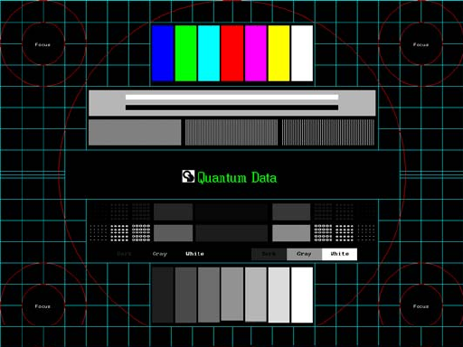
802BT/802R Video Test Generator User Guide 151
4. Using the Image knob, select the Master image.
The Master image appears on the connected HDMI display (as shown below).
5. To verify proper handling of the selected HDMI video format, check for the following in
the image on the HDMI display:
• scrambled raster
• jitter
• centering
• scaling anomalies
• resolution patches (for clarity)
• sparkling or missing pixels

152 Chapter 9 Testing HDMI Sink Devices
6. Using the Image knob, select the Ramp image.
The Ramp image appears on the connected HDMI display (as shown below).
7. To verify proper handling of the selected HDMI video format, check for glitches in the
image on the HDMI display.
8. Using the Image knob, select additional images (as desired) to verify proper handling
of the selected HDMI video format.
9. To test another HDMI format, return to step 3.
Testing HDMI video pixel repetition
The EIA/CEA-861-B standard defines a number of progressively-scanned gaming formats
which support variable horizontal resolution. These formats maintain a fixed 2880-pixel
format timing and use pixel repetition to provide 10 different effective horizontal
resolutions. A special blanking scheme further reduces the number of active pixels (to
those listed in the table below), thereby providing a horizontal safe area that insures that
all of the pixels in a game will be visible on overscanned HDMI displays.
To support HDMI gaming format and pixel repetition testing, the generator allows you to
sequentially apply pixel repetition (up to 10 times) to a unique image. As the pixel
repetition factor is increased, the horizontal resolution of the displayed image will decrease
as shown the table below.
Pixel repetition factor
(image version) Horizontal resolution
0 2880 pixels/line
1 2560 pixels/line
2 1280 pixels/line

802BT/802R Video Test Generator User Guide 153
To test an HDMI display using HDMI pixel repetition:
1. Connect an HDMI display to the Tx connector on the generator.
2. If necessary, set up the generator for HDMI output.
•See “Setting up the generator for HDMI operation” on page 147 for steps on setting
up the generator for HDMI operation.
3. Using the Format knob, select the HDMI gaming format you want to test.
Note: Gaming formats on the generator have the characters "4x" in their names (such
as “480i4x29” or “576i4x25”). For a listing of all HDMI formats, see the table on page
149.
4. Using the Image knob, select the PixelRep image.
The PixelRep image appears on the connected HDMI display (as shown below).
5. Press and release the Step key.
The Step key illuminates.
3 853 pixels/line
4 640 pixels/line
5 512 pixels/line
6 427 pixels/line
7 366 pixels/line
8 320 pixels/line
9 284 pixels/line
10 256 pixels/line
Pixel repetition factor
(image version) Horizontal resolution
154 Chapter 9 Testing HDMI Sink Devices
6. Using the Image knob, select the appropriate image version number (1-10).
Note: The image version number correlates with the pixel repetition factor.
The pixel repetition factor appears in the center of the image.
7. To verify proper handling of the selected HDMI gaming format, check the following in
the image on the HDMI display:
• The horizontal active area is resized to the appropriate number of clocked pixels
using vertical bars to the left and right of the default (2880 pixel) image.
• The white vertical borders and circles in the active area appear thicker.
• The white text in the center of the active area appears stretched and bigger.
8. Using the Image knob, select additional pixel repetition factors (as desired) to verify
proper handling of the selected HDMI gaming format using variable horizontal
resolutions.
9. When finished, press and release the Step key.
The light on the Step key extinguishes.
10. To test another HDMI gaming format, return to step 3.

802BT/802R Video Test Generator User Guide 155
Testing HDMI audio
This section provides steps on how to test handling of audio packets by an HDMI display.
Testing can be performed using audio originating from both internal (generator) and
external sources. The generator supports both 2-channel SPDIF audio from internal
source and external source and up to 8-channel audio from an internal audio source.
There are seperate sets of images for testing 2-channel SPDIF audio and 8-channel
audio.
Testing 2-channel HDMI audio output from internal SPDIF source
To support testing of HDMI audio, the 802 generator provides two-channel LPCM audio
(using an internally-generated sinewave) at the highest audio sampling rate (48 kHz).
Multiple scenarios are provided that allow you to test one or both audio channels at
different amplitudes and frequencies, as well as test using the different supported
sampling rates.
The following table lists the images used to perform HDMI audio testing using an internal
audio source.
To test an HDMI display using HDMI audio from the generator:
1. Connect an HDMI display to the Tx connector on the generator.
2. If necessary, set up the generator for HDMI output.
•See “Setting up the generator for HDMI operation” on page 147 for steps on setting
up the generator for HDMI operation.
3. Using the Format knob, select either the DMT0660 or 480i2x29 format.
Image Description
AudioLR Left and right audio channel output with adjustable amplitude.
AudioLRf Left and right audio channel output with adjustable frequency.
AudioRAT Left and right audio channel output with adjustable sampling rate.
Audio_L Left audio channel output with adjustable amplitude.
Audio_Lf Left audio channel output with adjustable frequency.
Audio_R Right audio channel output with adjustable amplitude.
Audio_Rf Right audio channel output with adjustable frequency.
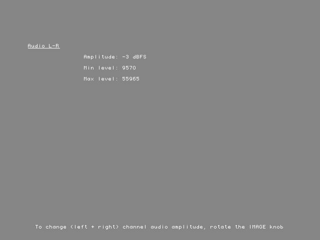
156 Chapter 9 Testing HDMI Sink Devices
4. Using the Image knob, select the appropriate image (see table above).
The image appears on the connected HDMI display. The image shows the current
settings for the HDMI audio output. For example, the AudioLR image is shown below.
5. Press and release the Step key.
The Step key illuminates.
6. Using the Image knob, adjust the amplitude, frequency, or sampling rate (based on the
selected image) of the HDMI audio output.
7. To verify proper HDMI audio handling, check the following on the HDMI display:
• Audio is output from the proper channels (left, right, or both).
• When amplitude is adjusted, the volume is subsequently changed.
• When frequency is adjusted, the pitch is subsequently changed.
8. When finished, press and release the Step key.
The light on the Step key extinguishes.
9. To test another HDMI audio output type, return to step 4.

802BT/802R Video Test Generator User Guide 157
Testing 8-channel HDMI audio output from internal source
To support testing of HDMI audio, the 802 generator provides 8-channel LPCM audio
(using an internally-generated sinewave) at the highest audio sampling rate (192 kHz).
Multiple scenarios are provided that allow you to test one or both audio channels at
different amplitudes and frequencies, as well as test using the different supported
sampling rates.
The following table lists the images used to perform HDMI audio testing using an internal
audio source.
To test an HDMI display using HDMI 8-channel audio from the generator:
1. Connect an HDMI display to the Tx connector on the generator.
2. If necessary, set up the generator for HDMI output.
•See “Setting up the generator for HDMI operation” on page 147 for steps on setting
up the generator for HDMI operation.
3. Using the Format knob, select either the DMT0660 or 480i2x29 format.
Image Description
Audio_1 Channel 1 output with adjustable amplitude.
Audio_1f Channel 1 output with adjustable frequency.
Audio_2 Channel 2 output with adjustable amplitude.
Audio_2f Channel 2 output with adjustable frequency.
Audio_3 Channel 3 output with adjustable amplitude.
Audio_3f Channel 3 output with adjustable frequency.
Audio_4 Channel 4 output with adjustable amplitude.
Audio_4f Channel 4 output with adjustable frequency.
Audio_5 Channel 5 output with adjustable amplitude.
Audio_5f Channel 5 output with adjustable frequency.
Audio_6 Channel 6 output with adjustable amplitude.
Audio_6f Channel 6 output with adjustable frequency.
Audio_7 Channel 7 output with adjustable amplitude.
Audio_7f Channel 7 output with adjustable frequency.
Audio_8 Channel 8 output with adjustable amplitude.
Audio_8f Channel 8 output with adjustable frequency.
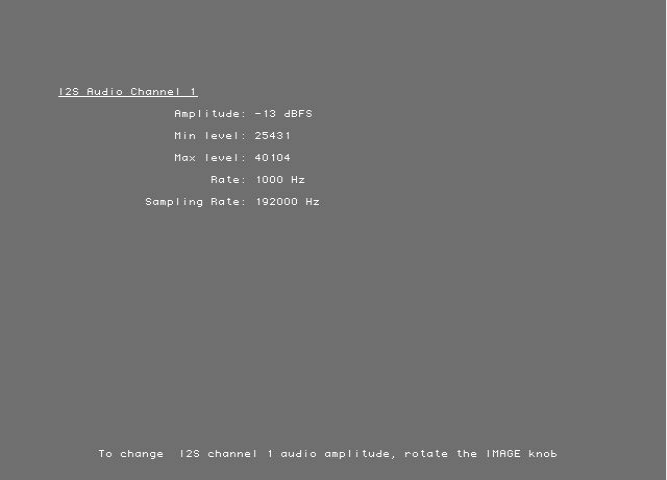
158 Chapter 9 Testing HDMI Sink Devices
4. Using the Image knob, select the appropriate image (see table above).
The image appears on the connected HDMI display. The image shows the current
settings for the HDMI audio output. For example, the Audio_1 image is shown below.
5. Press and release the Step key.
The Step key illuminates.
6. Using the Image knob, adjust the amplitude or frequency (based on the selected
image) of the HDMI audio output.
7. To verify proper HDMI audio handling, check the following on the HDMI display:
• Audio is output from the proper channels.
• When amplitude is adjusted, the volume is subsequently changed.
• When frequency is adjusted, the pitch is subsequently changed.
8. When finished, press and release the Step key.
The light on the Step key extinguishes.
9. To test another HDMI audio output type, return to step 4.
Testing HDMI audio using an external audio source
The generator provides basic, two-channel LPCM audio signals. However, it can encode
multichannel audio signals from an external SPDIF source (such as a DVD player) with the
HDMI content stream.
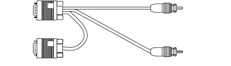
802BT/802R Video Test Generator User Guide 159
To test an HDMI display using HDMI audio from an external source:
1. Connect an HDMI display to the Tx connector on the generator.
2. Connect the external audio source to the AV connector on the generator using the
RCA-to-VGA cable (part 30-00148) provided with the generator, as shown below:
3. If necessary, set up the generator for HDMI output.
•See “Setting up the generator for HDMI operation” on page 147 for steps on setting
up the generator for HDMI operation.
4. Using the Format knob, select an appropriate format for the connected HDMI display.
5. Using the Image knob, select any desired image.
6. Using a terminal emulator, establish a terminal connection with the generator.
7. Configure the generator to use an external audio source by entering the following
command:
SDMG 2
FMTU
8. Set the sample frequency to match the frequency of the external source by entering the
following command:
ARAT 44.1E3 (example only)
Alternatively configure the generator to detect the audio sampling rate from the channel
header of the incoming digital audio.
ARAT 0.0
Note: The default frequency is 48 kHz (which is used by DVD players). However, if the
external source is an audio CD played on a DVD player, the player will output S/PDIF
with a sampling rate of 44.1 KHz (not 48 KHz). In this case, set the sampling frequency
to 44.1 kHz (or reload the format, which will detect the sampling frequency
automatically).
9. Turn on the external audio source.
The external audio signal will be encoded into the HDMI signal.
Note: The generator cannot independently control external source channels. You must
use the device generating the audio signal to control the channels.
To audio source
Red
White
To AV
connector
160 Chapter 9 Testing HDMI Sink Devices
10. To verify proper HDMI audio handling, check the following on the HDMI display:
• Audio is output from the proper channels (left, right, or both).
• When the volume is adjusted at the external source, the volume is subsequently
changed.
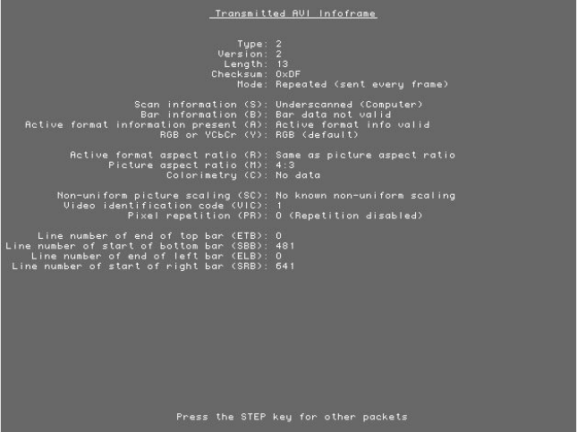
802BT/802R Video Test Generator User Guide 161
Testing HDMI InfoFrames
This section provides steps on how to test handling of auxiliary (InfoFrame) packets by an
HDMI display. The generator loads and sends default Auxiliary Video Information (XAVI),
Audio (XAUD), and Source Product Description (XSPD) InfoFrame packet buffers to the
display for each format (see table on page 149 for a listing of HDMI formats). The XAVI
and the XAUD InfoFrame packets are sent at every frame (repeated mode), while the
XSPD is sent only once. The XMPG and XGIF InfoFrames are gated off and not enabled.
Viewing InfoFrame contents
The 802 generator provides a convenient method for monitoring the InfoFrame content of
the transmitted HDMI signal.
To view current HDMI InfoFrame contents transmitted from the generator:
1. Connect an HDMI display to the Tx connector on the generator.
2. If necessary, set up the generator for HDMI output.
•See “Setting up the generator for HDMI operation” on page 147 for steps on setting
up the generator for HDMI operation.
3. Using the Format knob, select the HDMI format you want to test.
4. Using the Image knob, select the PacketTx image.
The PacketTx image appears on the connected HDMI display. The image shows the
current settings for the AVI InfoFrame output.

162 Chapter 9 Testing HDMI Sink Devices
5. Press and release the Step key.
The Step key illuminates.
6. Using the Image knob, select the appropriate InfoFrame type.
The contents of the appropriate InfoFrame output appears on the HDMI display.
7. When finished, press and release the Step key.
The light on the Step key extinguishes.
Testing with Active Format Description (AFD)
When transporting HDMI video images from a source to a display, different formats may
be used between the content, transmission signal, and display. To provide compatibility
between the different formats, Active Format Description (AFD) is used.
AFD describes the portion of the coded video frame that is "of interest" (or “active”). The
appropriate AFD information is transmitted with the video to the HDMI display as part of
AVI InfoFrame packets. Using AFD information, the display is able to present the image
optimally.
For AFD testing, the generator allows you to apply different AFD cases using the AFDtest
image, which provides 12 different cases (as image versions) for both 4:3 and 16:9
displays. As each image version appears, the appropriate AFD information is sent with the
video to the display.
The following table lists the AFD cases (as specified in the ETSI TR 101 154 v.1.4.1
standard) that are provided by the generator.
AFD case
Image
Version
(4:3 Format)
Image
Version
(16:9 Format) Aspect Ratio of Active Area
2 8 7 box 16:9 (top)
3 5 4 box 14:9 (top)
4 9-12 9-12 box > 16:9 (center)
8 0 6 Same as the signal format
9 1 1 4:3 (center)
10 7 8 16:9 (center)
11 4 3 14:9 (centered)
13 3 5 4:3 (with shoot and protect 14:9 center)
14 6 2 16:9 (with shoot and protect 14:9 center)
15 2 0 16:9 (with shoot and protect 4:3 center)
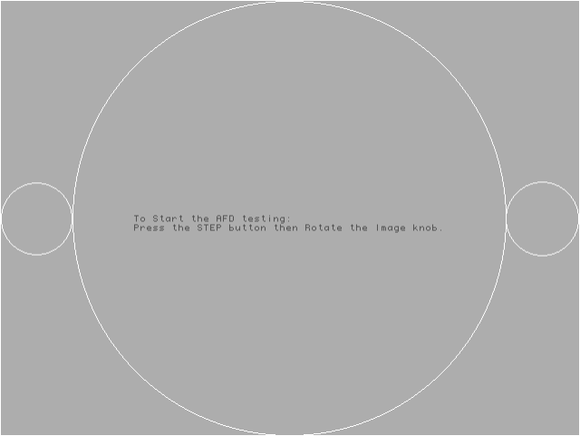
802BT/802R Video Test Generator User Guide 163
To test an HDMI display’s ability to support AFD:
1. Connect an HDMI display to the Tx connector on the generator.
2. If necessary, set up the generator for HDMI output. See “Setting up the generator for
HDMI operation” on page 147.
3. Using the Format knob, select an appropriate video signal format. See the table on
page 149 for a listing of HDMI formats.
4. Using the Image knob, select the AFDtest image.
The AFDtest image appears on the connected HDMI display (as shown below).
5. Press the Step key.
The Step key illuminates, and the following image appears.
6. Using the Image knob, select an AFD scenario by selecting the appropriate image
version number (1-12).
Note: The image version number corresponds with the AFD case (or code). See the
table on page 162 for a listing of the image numbers that correspond with each AFD
case.
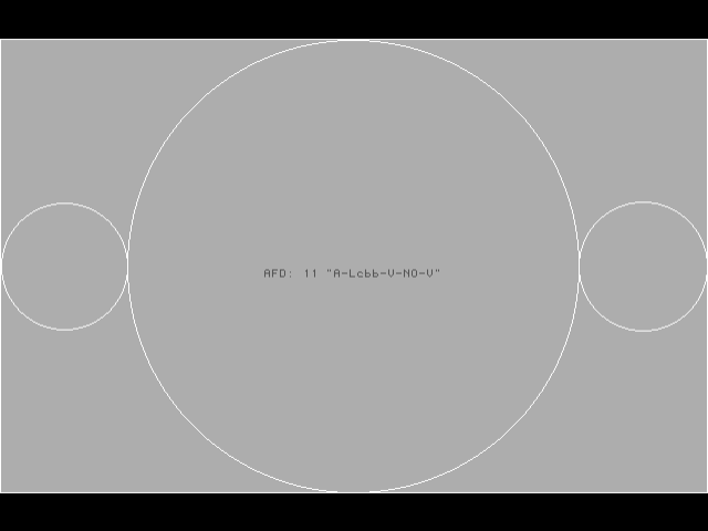
164 Chapter 9 Testing HDMI Sink Devices
The image appears on the HDMI display. For example, the image representing AFD
case 11 (image version 4) on a 4:3 display is shown in the example below.
7. Using the selected AFD scenario, verify that the HDMI display presents the image
correctly.
Note: Displays use the AFD information to determine how to present an image.
Different displays may present HDMI video with the same AFD differently.
8. Using the Image knob, select additional AFD cases (as desired).
9. When finished, press and release the Step key.
The light on the Step key extinguishes.
166 Chapter 10 Testing EDID
Overview
This chapter provides procedures for testing EDID generation and handling. The
generator can be configured to emulate an HDMI/DVI source when testing HDMI/DVI sink
(display) devices or it can be configured to emulate an HDMI/DVI sink (display) device
when testing an HDMI/DVI source device.
Some of the EDID tests require the analyzer option. These include testing the EDID
handling capabilities of a source device and the HDMI compliance EDID testing for a sink
(display) device. Viewing EDID of a display and writing to a display is a generator function
and does not require the analyzer option.

802BT/802R Video Test Generator User Guide 167
EDID testing for source devices
The generator can emulate an HDMI/DVI sink (display) in order to test HDMI source
devices.
Testing response of source to EDID
The analyzer can emulate different HDMI/DVI displays using a built-in, configurable EDID
structure. With this capability an HDMI/DVI source device can be tested for its ability to
handle an EDID structure received from virtually any DDC-compatible display. You first
have to configure the generator to support the HDMI/DVI signal source and enable
measuring of internal signals. You then configure the EDID in accordance with a particular
display. Use the following procedures.
To set up the generator to perform HDMI/DVI testing:
1. Hold down the G and B keys, and then power on the generator.
The following message appears on the front panel LCD.
2. Release the G and B keys.
The generator is placed in Digital Friendly mode.
3. Hold down the R and ACS keys, and then cycle the power to the generator.
The following message appears on the front panel LCD.
4. Hold down the Step, G, and B keys while starting the genertor, until Status display
appears on the LCD.
Special: keys
Digital friendly
Special: keys
hot-plug formats
168 Chapter 10 Testing EDID
5. Release the Step, G, and B keys to enable status display on the generator (see
example below).
The format status on the LCD will indicate whether the unit is outputting HDMI or DVI
signal protocol from the Tx connector. An “H” in the format status (H8C in the example
above) indicates HDMI output; a “D” in the format status indicates DVI output.
Note: With the compliant Hot-plug Formats mode active and a hot-plug detected, the
generator automatically selects the appropriate TMDS output signal protocol (HDMI or
DVI) for the attached display (via EDID read).
To configure the analyzer for internal measurements:
1. Connect a digital display with the DVI or HDMI transmitter on the generator.
2. Select the Analzyer image.
The Analyzer Setup Utility appears on the connected display.
3. Press and release the Step key.
The Step key illuminates and the Analyzer Images field is highlighted.
H31 D8C=DMT0659
V60 0=SMPTE133
Video type Format name
Image name
Color depth
Color space
Image version
802BT/802R Video Test Generator User Guide 169
4. Using the Image knob, select the ON setting to enable analyzer images.
5. Using the Format knob, select the Auto Based On field.
6. Using the Image knob, select CURRENT in the highlighted field to measure the
HDMI/DVI signal originating internally from the generator.
7. Press and release the Step key to save the currently displayed parameters.
The light on the Step key extinguishes, and the new settings are implemented for
analyzer mode operation.
To configure the analyzer to emulate the EDID structure of a display:
1. Determine the HDMI/DVI display you wish to emulate and if possible obtain a text file
of its EDID.
Note: This can be obtained from the manufacturer or by reading the EDID using the
HDMI/DVI generator. For procedures on reading the EDID of a display with the
generator, please refer to “Viewing EDID from a display” on page 171.
2. Connect an HDMI/DVI cable between the HDMI/DVI Tx and Rx connectors on the
generator.
3. Using a terminal emulator, establish a terminal session with the generator (see page
14).
4. Modify the EDID structure in the generator using the XDID and DIDU commands.
For example, to change the color characteristics of the EDID structure (a total of 10
bytes starting at byte 19), you could use the following command strings:
XDID 19 A E88A82A0564796240F48
DIDU
To program multiple segments (or the entire EDID structure) at once, create a text file
containing the EDID. Then send the text file to the generator using your terminal
emulator’s file transfer feature.
The following commands write the entire EDID block 0:
XDID 0 80 00FFFFFFFFFFFF005A63118F01010101130D010380221B782A4706A55C47
9C251E4F54BFEF008180310A010101010101010101010101302A009851002A40307013
00520E1100001E000000FF004132333033313931353335390A000000FD00324B1E530E
000A202020202020000000FC0056583730302D330A20202020200095
DIDU
5. To verify the EDID structure, use the EDID? query. This command will display the entire
EDID structure in ASCII hex format.
To view a specific segment of EDID, use the I2CR? query. This command will display
the requested EDID in ASCII hex format.
6. If desired, use the STRG command to stretch the SCL low signal for 5 ms in the
analyzer’s receiver.
170 Chapter 10 Testing EDID
To test the source device’s handling of the EDID:
1. Connect the HDMI/DVI source device to the HDMI/DVI Rx connector on the generator.
Upon receiving the HDMI/DVI signal at the HDMI/DVI Rx connector, the generator
sends the EDID structure to the source device.
2. At the HDMI/DVI source device, compare the processed EDID information with the
EDID structure defined in the generator.

802BT/802R Video Test Generator User Guide 171
EDID testing for sink devices
The generator can emulate an HDMI, DVI or VGA source device in order to test HDMI, DVI
or VGA displays. This includes viewing EDID from a display and writing EDID data to a
display. The generator can test an HDMI display device’s EDID structure and transmission
in accordance with the HDMI Compliance Test Specification 1.0.
Viewing EDID from a display
You can use the generator to view EDID from a DDC-compliant VGA, HDMI or DVI display
connected with the generator.
To view EDID information from an HDMI, DVI or VGA display:
1. Connect an HDMI, DVI or VGA device to the HDMI, DVI or VGA Tx connector on the
generator.
2. Using the Format knob, select an appropriate format for the HDMI, DVI or VGA display
connected to the HDMI, DVI or VGA Tx connector.
Alternatively, to automatically configure the Format knob list based on the EDID of the
display, hold down the R key, and then press and release the ACS key.
3. Using the Image knob, select the EdidData image.
The EdidData image displays the first block of data.
4. Press the Step key, turn the Image knob to the first EDID block.
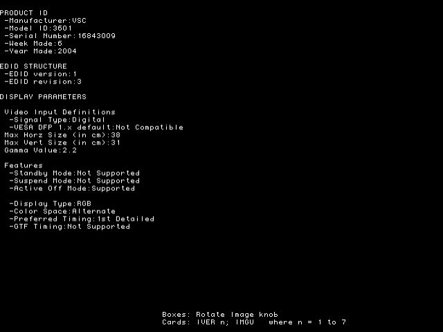
172 Chapter 10 Testing EDID
5. To view parsed EDID information, press and release the Step key, and then turn the
Image knob to view additional blocks and parsed data.
To query EDID information from an HDMI, DVI or VGA display via the command line:
1. Using a terminal emulator, establish a terminal session with the generator (see page
14).
2. To view the current EDID in ASCII hex format, use the EDID? command.
To view a specific segment of EDID, use the I2CR? command.
Querying the EDID from the command line enables you to create a text file with the
EDID in order to configure the analyzer to emulate the display device.
Writing EDID data to a display
You can modify the EDID in the connected display, if the EEPROM in the display is
writable.
To modify the EDID in a display:
1. Connect the display to be modified to the HDMI, DVI or VGA Tx connector on the
generator.
2. Using a terminal emulator, establish a terminal session with the generator (see page
14).
802BT/802R Video Test Generator User Guide 173
3. Use the I2CW command to modify the EDID structure in the connected display.
For example, to change the color characteristics of the EDID structure (a total of 10
bytes starting at byte 19), you could use the following command string:
i2cw eprom1 a0 25 A E88A82A0564796240F48
4. To program multiple segments or a complete EDID structure, use a text editor to enter
the commands in a text file, and then download the file to the generator from a terminal
emulator program such as HyperTerminal.
Testing EDID in HDMI sink device for HDMI compliance
The analyzer supports the following EDID and video HDMI compliance tests in
accordance with the HDMI Compliance Test Specification 1.0 (CTS):
• Test ID 8-1: EDID Readable
• Test ID 8-2: EDID VESA Structure
• Test ID 8-3: CEA Timing Extension Structure
• Test ID 8-17: 861B Format Support Requirements
• Test ID 8-18: HDMI Format Support Requirements
• Test ID 8-19: Pixel Encoding Requirements
• Test ID 8-20: Video Format Timing
These tests are intended for in-house testing of products before submission to an HDMI
ATC for full certification testing.
Overview of HDMI compliance testing
HDMI compliance testing is conducted through the generator’s transmit HDMI connector.
A standard HDMI-to-HDMI cable is used between the device under test and the generator.
The generator must be placed in the digital friendly mode and set to output HDMI signals,
which is the default configuration for HDMI equipped generators.
After making the physical connections you need to specify the capabilities of the sink
display under test. This enables the generator to compare the expected results with the
actual results measured from the display. Use the CDF_Sink image, which is based on the
Capabilities Declaration Form (Appendix 3) of the Compliance Test Specification, to
specify the display capabilities.
To test the sink device, load the EdidHDMI image, and turn the image knob to advance
through each test listed above in sequence.

174 Chapter 10 Testing EDID
Testing HDMI sink devices for EDID compliance
The procedures for EDID and video testing of HDMI sink devices in accordance with the
HDMI Compliance Test Specification 1.0 are provided below.
Note: The EDID and video tests should be performed in sequence as a single test series.
Each test is dependent on successful completion of the previous test.
To set up the generator for HDMI compliance testing:
1. Hold down the G and B keys, and then power on the generator.
The following message appears on the front panel LCD.
2. Release the G and B keys.
The generator is placed in Digital Friendly mode.
3. Select and apply a valid HDMI format such as DMT0660 either by turning the Format
knob or entering the following command:
FMTL DMT0660; FMTU
4. Load the GenOps image to verify that the generator is configured to output HDMI (that
it is not in DVI-only mode).
The generator’s default configuration is to output HDMI. Note that the display status
mode will indicate that the generator is in HDMI mode with an “H” character. You can
also verify that the generator is putting out an HDMI signal by issuing the following
command:
HDMI?
The returned value should be 1 indicating HDMI output.
Special: keys
Digital friendly
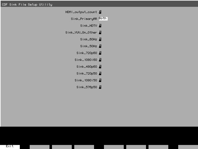
802BT/802R Video Test Generator User Guide 175
To specify the capabilities of the sink device:
1. Load the CDF_Sink image, which is shown below.
2. Press and release the Step key to enable selection of each field. Use the Format knob
to position the cursor. Use the Image knob to choose values.
For example, if your display supports both 4:3 and 16:9 aspect ratios, set the
Sink_PrimaryAR field to Both.
3. Press the Step (Exit) key to save the settings. The settings are stored until you change
them, and are kept if the generator is restarted.
To initiate the compliance testing:
1. Load the EdidHDMI image.
2. Press and release the STEP key, then turn the Image knob to progress through the
tests in the sequence below.
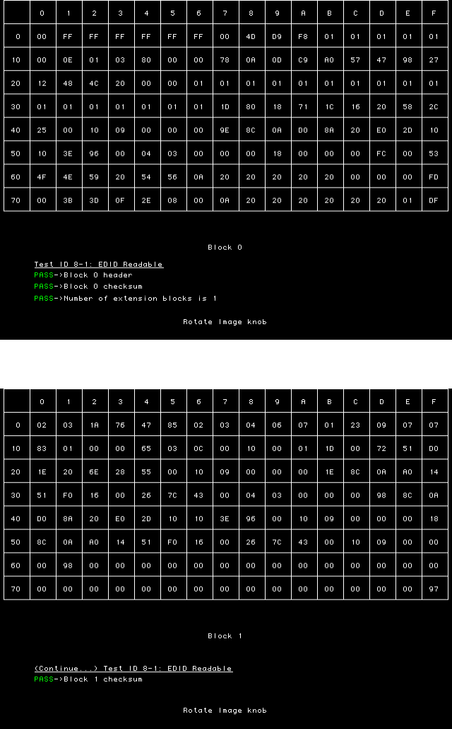
176 Chapter 10 Testing EDID
Testing EDID readability (Test ID 8-1) - This test verifies that the EDID can be read
properly. The screens are shown below.
(
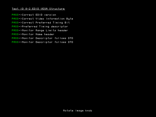
802BT/802R Video Test Generator User Guide 177
Testing EDID VESA structure (Test ID 8-2) - This test verifies that the data in the base
EDID 1.3 block and basic EDID Extension handling is correct and meets all aspects of the
relevant specifications.
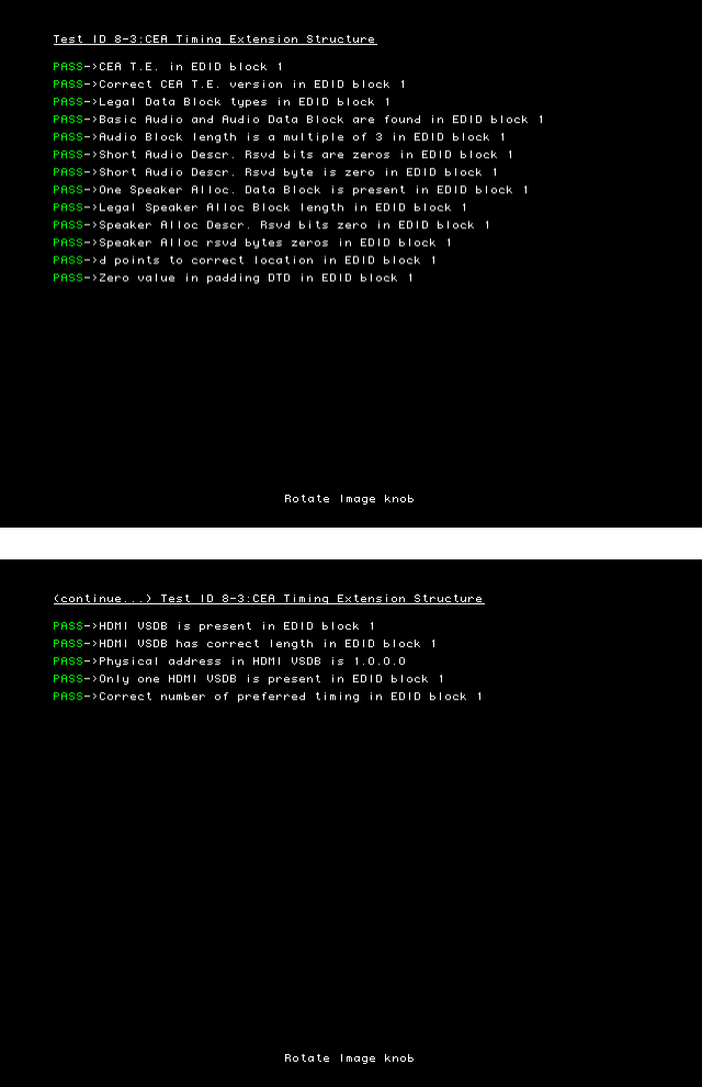
178 Chapter 10 Testing EDID
Testing CEA timing extension structure (Test ID 8-3) - This test verifies that the data in any
CEA Timing Extension present in EDID is formatted properly and meets all aspects of the
relevant specifications.
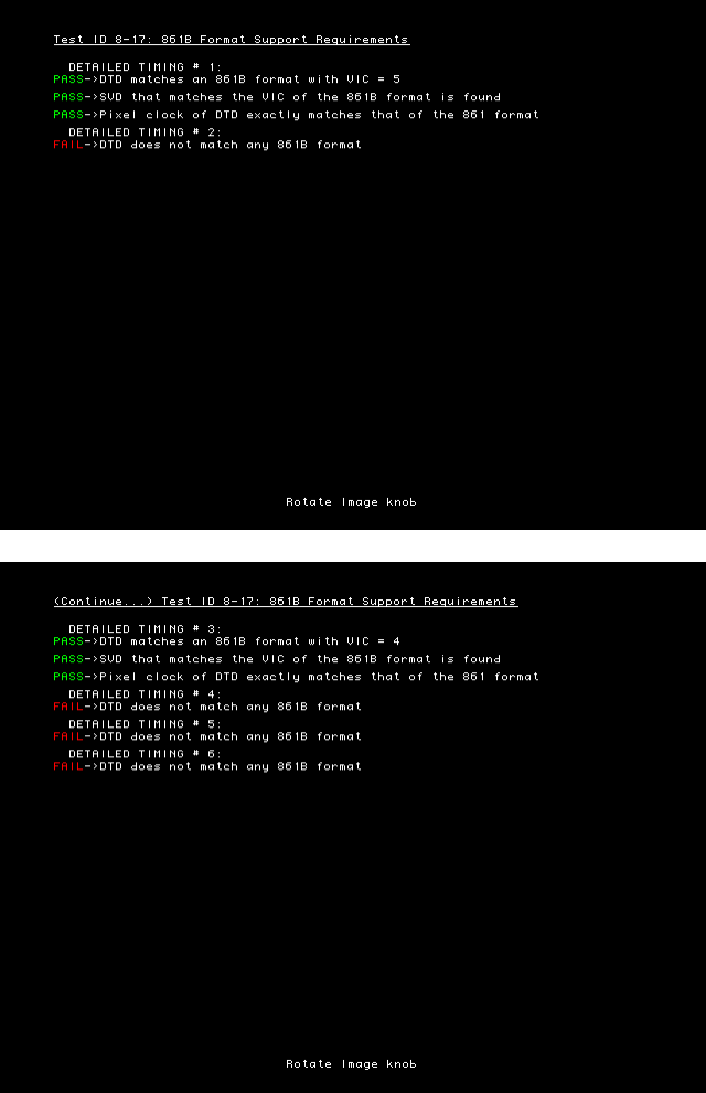
802BT/802R Video Test Generator User Guide 179
Testing 861B Format Support Requirements (Test ID 8-17) - This test verifies that no
861B-defined video format is declared only in a Detailed Timing Descriptor.
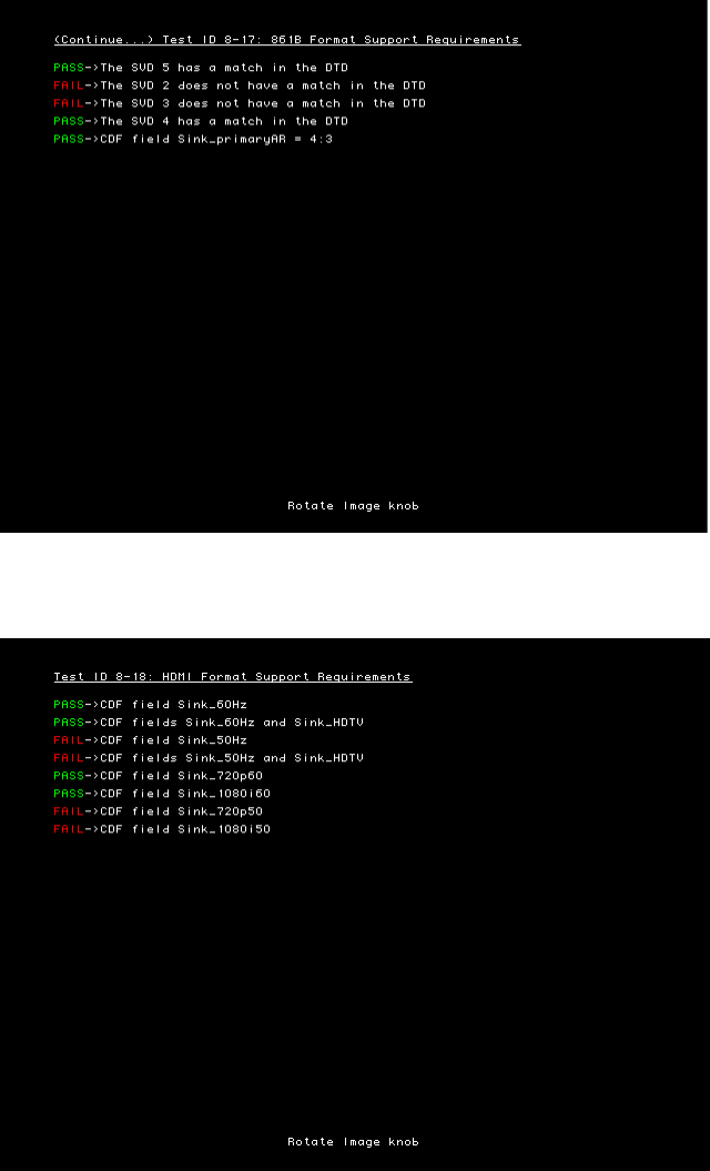
180 Chapter 10 Testing EDID
Testing HDMI Format Support Requirements (Test ID 8-18) - This test verifies that Sink
DUT indicates support for all required video formats in its EDID.
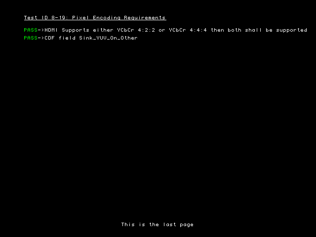
802BT/802R Video Test Generator User Guide 181
Testing Pixel Encoding Requirements (Test ID 8-19) - Verifies that the Sink supports
YCpCr pixel encoding when required.
To create a knob list of all formats supported by the display:
1. Press and release the STEP key to return to the initial compliance testing screen.
The STEP key should be extinguished.
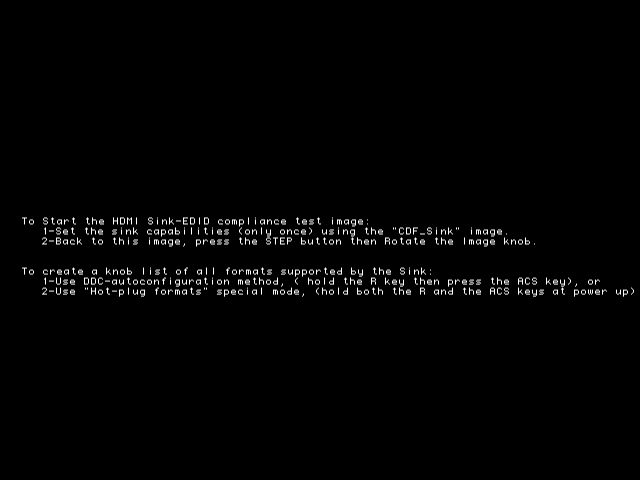
182 Chapter 10 Testing EDID
2. Press and hold the R key and then press and release the ACS key. Alternatively power
off the generator, press and hold both the R and ACS keys then power up the generator
to configure the generator knob list with the hot plug formats.
The initial compliance test screen re-appears and the Format knob list includes only
those formats in the display EDID.
Visual verification of formats
Additional visual inspection of Tests 8-19 and 8-20 is necessary to ensure that each
format can be loaded and displayed at each pixel encoding and at its minimum and
maximum pixel rate.
Test ID 8-19 involves testing each format with different YCbCr pixel encoding: 4:4:4 pixel
sampling and 4:2:2 sampling. Test ID 8-20 requires that each format listed in the EDID be
be tested at two different pixel clock frequencies. The two different frequencies shall be the
minimum and maximum permitted by a Source. For 50Hz formats, these values are
49.75Hz and 50.25Hz (50Hz ± 0.5%). For 59.94Hz or 60Hz formats, these frequencies are
59.64Hz (59.94Hz – 0.5%) and 60.3Hz (60Hz + 0.5%). The tested pixel clock frequency
accuracy shall be ±0.05%.
A separate listing of the formats is provided on the Format knob list to support this visual
inspection testing. The nomenclature for visual inspection testing of maximum and
minimum pixel rate is of the form shown in the example below:
802BT/802R Video Test Generator User Guide 183
Example
•SVD – Short Video Descriptor.
•01 – EIA/CEA-861-B Format Video Identification Code (for example 01, 02, 06, etc.
listed on page 149)
•Y2 – Y indicates color difference. 2 = 4:2:2 pixel sample encoding. 4 = 4:4:4.
•1 – Represents DMT0659 format, which is first format (index 1) listed under video
identification code 01 in table on page 149.
The nomenclature for visual inspection testing for pixel encoding is of the form shown in
the example below:
•SVD – Short Video Descriptor.
•01 – EIA/CEA-861-B Format Video Identification Code (for example 01, 02, 06, etc.
listed on page 149)
•H – Indicates that format is using maximum (H = High) or minimum (L = Low)
frequency required by compliance test.
•01 – Index of format as listed under video identification code onpage 149.
To visually validate the formats in the knob list for pixel encodings and pixel rate:
1. Select an image suitable for testing the display type by turning the Image knob or
entering the appropriate command. For example to display the Master image enter:
IMGL Master; IMGU
2. Turn the format knob to display each of the formats in the knob list that begin with SVD.
Each format should display properly.
3. Turn the format knob to display each of the formats in the knob list.
Each format should display properly.
Short
Video
Descriptor
VIC Format
Index
01 YSVD 2
Component
color
sampling
1
Short
Video
Descriptor
VIC Format
Index
01 HSVD 0
Frequency
(High / Low)
1
184 Chapter 10 Testing EDID
802BT/802R Video Test Generator User Guide 185
11 Testing HDCP
You can use the generator, with the High-bandwidth Digital Content Protection (HDCP)
option installed, to test HDCP 1.0 and 1.1 compliant devices.
For more information about HDCP, see http://www.digital-cp.com/.
Topics in this chapter:
•Testing DVI or HDMI receiver with HDCP
•Testing HDCP between HDMI transmitter and DVI receiver
•Testing HDCP with static images
•Using command-line interface to control HDCP
•Troubleshooting HDCP errors
186 Chapter 11 Testing HDCP
Testing DVI or HDMI receiver with HDCP
This section describes how to test DVI and HDMI receivers with HDCP.
All DVI and HDMI options, including analyzer options, support HDCP production keys if
the HDCP option is installed. Some DVI options support both production and public keys.
To determine which HDCP keys your generator supports:
1. Load the GenStats image.
2. Verify that HDCP is listed under the Options heading, which indicates that the HDCP
option is installed, and that production keys are available.
3. If the following image names are listed on the LCD, then HDCP public (test) keys are
installed.
• HdcpA1B1
• HdcpA1B2
• HdcpA2B1
• HdcpA2B2
Note: With older firmware installed, you may be able to select these images, but an
“Image is not available” message is displayed on the display connected with the
generator. This message indicates that public keys are not installed.
To test HDCP with a DVI device:
1. Hold down the G and B key while starting the generator put the generator in digital
friendly mode.
Alternatively, enter the following command:
SROP 2
2. Connect the DVI transmitter on the generator to the device’s DVI receiver.
3. Select an appropriate HDCP test image.
If you are testing a device with a production key, select the HdcpProd(uction) image.
The HdcpProd image assumes that both the HDCP transmitter and receiver have a
production key.
If your generator supports public keys, select the appropriate image below. For
example, if the receiver has pubic key B2, and you want to use public key A1 in the
transmitter, then select the HdcpA1B2 image.
• HdcpA1B1
• HdcpA1B2
• HdcpA2B1
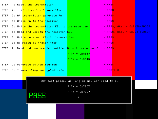
802BT/802R Video Test Generator User Guide 187
• HdcpA2B
The image will indicate if the test passed or failed. If the test fails, see “Troubleshooting
HDCP errors” on page 191.
4. To test another device, connect the cable to the new device.
The HDCP test starts automatically.
To test HDCP with an HDMI device:
1. Hold down the G and B key while starting the generator put the generator in digital
friendly mode.
Alternatively, enter the following command:
SROP 2
2. Connect the HDMI transmitter on the generator to the device’s HDMI receiver.
3. Select the HdcpProd(uction) image.
The image will indicate if the test passed or failed. If the test fails, see “Troubleshooting
HDCP errors” on page 191.
188 Chapter 11 Testing HDCP
Testing HDCP between HDMI transmitter and DVI receiver
HDCP 1.1-compliant devices must interoperate with HDCP 1.0 compliant devices using
the DVI protocol. Generators with an HDMI transmitter can be used to test HDCP with
devices that have an DVI receiver.
To test HDMI Tx with DVI Rx:
1. Hold down the G and B key while starting the generator put the generator in digital
friendly mode.
Alternatively, enter the following command:
SROP 2
2. Establish a command terminal connection with the generator, using HyperTerminal or
VGM.
3. At the R:> prompt, enter the following to set the HDMI transmitter into DVI mode, which
disables audio:
HDMI 0
ALLU
The DVI mode setting is saved until you change it.
4. Use an HDMI-to-DVI cable (provided with HDMI generator) to connect the HDMI
transmitter to the DVI receiver.
5. Load the HdcpProd image. This image assumes that both the transmitter and receiver
are using production keys.
The image will indicate if the test passed or failed. If the test fails, see “Troubleshooting
HDCP errors” on page 191.
To change HDMI transmitter from DVI to HDMI mode:
1. Establish a command terminal connection with the generator, using HyperTerminal or
VGM.
2. At the R:> prompt enter the following to invoke the HDMI mode:
HDMI 1
ALLU
802BT/802R Video Test Generator User Guide 189
Testing HDCP with static images
The standard HDCP test images have color bars in the background. A special mode is
available for testing HDCP with any static background image you specify.
To test HDCP with a different background image:
1. Turn on the generator while holding down the G and ACS keys until hdcp tester is
displayed.
Alternatively, enter the following command:
SROP 8192
2. Select a format that is supported by the display, and then load any static image.
The HDCP test begins automatically when you connect the display.
If the HDCP test passed, the generator displays the image you specified. If the test
failed, the display will remain blank. See “Troubleshooting HDCP errors” on page 191.

190 Chapter 11 Testing HDCP
Using command-line interface to control HDCP
The command interface can control HDCP tests in automated testing environments.
To run HDCP test from command prompt:
1. Establish a command terminal connection with the generator using VGM or
HyperTerminal.
2. Connect the device to be tested to the transmitter on the generator.
3. At the R:> prompt, enter the following command to run the HDCP test:
HDCP?
HDCP? command
The HDCP? command is the only command used to control HDCP tests.
Syntax HDCP? [ A1 | A2 ] [ B1 | B2 ] [frames]
Where frames is the number of frames to be tested. The default number of frames is 512.
Example These examples demonstrate how to specify which test to run.
Error codes These errors may occur when using the HDCP? command.
Command Result
hdcp? Runs test with production keys for 512 (default) frames, and then returns 0 if
the test passed, or an error number if the test failed.
hdcp? 2000 Run test with production keys for 2000 frames.
hdcp? a1 b1 Runs test with public keys A1 and B1 for 512 frames.
hdcp? a2 b1 2000 Runs test with public keys A2 and B1 for 2000 frames.
Code Meaning
9520 HDCP key combination is not supported. Valid combinations are A1/B1,
A2/B1, A1/B2, and A1/B2.
9521 Test started successfully, but failed during test.
9522 Test did not start.
9508 Specified keys are not present.

802BT/802R Video Test Generator User Guide 191
Troubleshooting HDCP errors
Common problems
This table describes possible solutions to problems that may occur during HDCP testing.
Running HDCP test in step mode
The generator normally runs the steps in the HDCP test automatically. If the test fails, the
test is restarted after a few seconds, which makes it difficult to read values at the step
where the test failed. Run any HDCP test in manual mode to pause the test after each
step.
To run the HDCP test in step mode:
1. At any step during an HDCP test, press the Step key.
2. Turn the Image knob to advance to the next step. If you are using an PCI-based
generator, use the commands displayed on the screen to advance to the next step.
3. Press the Step key again to return to automatic mode.
Running an HDCP self-test
An HDCP self-test checks that HDCP authentication is working properly between the
transmitter and receiver on the analyzer. This test can also be used to confirm that a cable
is not interfering with HDCP authentication, and that the DDC clock and DDC data pins,
which the I2C buss uses, are working correctly.
Problem Solution
Test fails at step 3 Transmitter could not read Bksv from the receiver, Bksv was read cor-
rectly but is a wrong value, or an I2C error occurred.
If the EdidData image loads, the I2C communication is working properly.
Verify that the Bksv value is 5 bytes (that is, 40 bits of which 20 zeros
and 20 ones) by reading the value from the test image.
HdcpProd image flashes
repeatedly at step 9
Restart the generator while holding down the Outputs key, or use the
SROP 16 command, which starts the generator in “Reset HDCP Rx by
gating clock” mode.
HdcpProd image is
unavailable
The HdcpProd image requires the HDCP production key option to be
installed in the generator. To determine if this option is installed, view
the GenStats image. The HDCP option will be listed under the Options
heading if it is present.

192 Chapter 11 Testing HDCP
To run an HDCP self-test:
1. Hold down the G and B key while starting the generator put the generator in digital
friendly mode.
Alternatively, enter the following command:
SROP 2
2. Connect your cable to the Rx and Tx on the analyzer.
3. Select the HdcpProd image.
When testing a display, the HDCP test results are displayed on the display being tested.
When testing a cable, where no display is connected to the transmitter, test results are
displayed by the LCD display on the generator. If HDCP authentication is working
correctly, the name of the HdcpProd image on the LCD will be updated with Ri values
every 2 seconds. If HDCP is not working, the LDC display will remain static.
Understanding the HDCP test
Understanding what the generator does during an HDCP test can help you determine why
an HDCP test failed.
To determine which hardware is installed:
1. Load the GenStats image.
2. Compare the following table with the GenStats image to determine which hardware is
installed.
Test sequence for Broadcom transmitters:
1. The generator resets the transmitter and its HDCP engine.
GenStats information Hardware
DVI (SiI) (under Options) and DVI FPGA less
than F1 (under Generator Information)
Silicon Image
DVI (under Options) Broadcom
DVI Analyzer (under Options) Silicon Image
DVI II (under Options) and DVI FPGA F1 or
later (under Generator Information)
Silicon Image
DVI II (under Options) and DVI FPGA is earlier
than F1 (under Generator Information)
Broadcom
HDMI (under Options) Silicon Image
HDMI Analyzer (under Options) Silicon Image
802BT/802R Video Test Generator User Guide 193
2. If the “Reset HDCP Rx by gating clock” mode is enabled, the generator resets the
receiver, and gates off transmitter clock and data for 400 mS. Otherwise, the receiver
is not reset.
3. The transmitter reads the Bksv (HDCP receiver KSV), over the I2C bus, and verifies
that it has 20 zeros and 20 ones.
This step is the first interaction between the transmitter and receiver.
4. Receiver writes the receiver KSV to the transmitter.
5. Transmitter generates An (session random number).
6. Transmitter writes An to the receiver, using the I2C bus.
7. Transmitter writes the transmitter KSV to the receiver, using the I2C bus.
8. Load the transmitter keys.
9. The transmitter reads the Ri value (link verification response) from the receiver and
compares it with its own generated Ri value. They should match to proceed. If this step
fails, the test returns to step 1.
10. Generate authentication.
11. Transmitting encrypted data.
Test sequence for Silicon Image transmitters:
1. Reset the transmitter.
2. If the “Reset HDCP Rx by gating clock” mode is enabled, the generator initializes the
transmitter. Otherwise, do not initialize the transmitter.
3. Transmitter generates An (session random number).
4. Transmitter writes An to the receiver, using the I2C bus.
This step is the first interaction between the transmitter and receiver. The transmitter
reads the Bksv, over the I2C bus, and verifies that it has 20 zeros and 20 ones.
5. Write the transmitter KSV to the receiver.
6. Read and verify the receiver KSV.
7. Write receiver KSV to transmitter.
8. Ri ready at transmitter.
9. The transmitter reads the Ri value from the receiver and compares it with its own
generated Ri value. They should match to proceed. If this step fails, the test returns to
step 1.
10. Generate authentication.
11. Transmitting encrypted data.
194 Chapter 11 Testing HDCP
196 Chapter 12 Using Special Sync Output
Overview
The generator is equipped with a Special Sync BNC connector labeled S/S on the front
right side. You can configure the output of this video interface to output frame sync, line
sync, composite sync or a special probe pulse.
802BT/802R Video Test Generator User Guide 197
Operating special sync for probe pulse
The probe feature is used in connection with a programmable probe pulse that is available
on the S/S BNC. This pulse is most often used to trigger an oscilloscope or synchronize an
inspection camera. The probe feature allows you to position the leading edge of the probe
pulse anywhere within the video frame. This feature greatly facilitates troubleshooting by
enabling you to focus on specific video signal problems occurring anywhere in the video
signal.
Configuring the probe feature involves positioning the probe pulse in the desired location
on the video frame. You can do this either through the front panel or the command line
interface. The front panel display is most convenient if you are near the generator and not
using a computer or terminal. You can control the generator through the command line
interface either locally or remotely through the serial connection.
Front panel controls and indicators
To use the probe feature begin by first activating the probe feature through the generator
keys, and then positioning the pulse in the desired location by turning the Format knob
(horizontal position) and the Image knob (vertical position). The current position of the
pulse is shown on the LCD.
Probe coordinate numbering
Unlike ITU and SMPTE standards, Quantum Data standards count pixels, lines, and
coordinates beginning with the number zero (not one) to improve the mapping between
video signal specifications and modern computer graphics coordinates. The television
standards are accounted for by suppressing any half-active line that appears in an
equalizing interval and lengthening (to a full line) any half-active line that begins in the
active portion of a field. Vertical counting always begins with the leading edge of blanking
of the first field (not vertical sync). The first field is always defined as the field that includes
the top line of the displayed picture (Y:0). This definition is always true whether the total
number of active lines is odd or even.
With interlaced scanning, lines continue to be numbered sequentially throughout the
frame, beginning with the leading edge of blanking of the first field. Therefore, the first two
lines of blanking in the first field are numbered L:0 followed by L:1. If you have 525 total
lines and 486 of those are active, for example, the first two (blank) lines of the second field
would be numbered L:262 and L:263. The Y position continues to follow the visual order of
lines going from the top to the bottom of the screen. If the last line of blanking in the first
field is L:18, then L:19 corresponds to Y:0, L:20 to Y:2, L:21 to Y:4 and so on. In the
second field, L:282 would correspond to Y:1, L:283 to Y:3, L:284 to Y:5 and so on.

198 Chapter 12 Using Special Sync Output
Configuring the probe feature
This section describes how to configure the probe feature.
To enable the probe feature:
1. Deactivate the signal outputs of the generator by pressing the Outputs key. The light
on the Outputs key extinguishes.
2. Hold down the Step key, and then press and release the Outputs key. The LCD
displays a Probe feature message, and then the following screen.
3. Release the Step key.
Setting sensitivity of knobs
You can control the amount of distance traveled with each click of the Format and Image
knobs by using the ACS, DCS, and DSS keys. If neither ACS, DCS, nor DSS is selected,
then the amount of movement is increased exponentially as you move farther in a particular
direction and is reset when you change direction.
To set the sensitivity of the Format and Image knobs:
1. Press the appropriate key:
Controlling probe using generator controls
This section procedures for controlling the special sync probe through the front panel keys
and knobs.
To position the probe pulse in a specific location in the video signal:
1. Turn the Format knob to set the horizontal position of the probe pulse to the desired
pixel relative to the leading edge of the horizontal sync.
The horizontal position of the probe is simultaneously displayed in two different ways:
• The horizontal position P:nnnn is given in pixels relative to the leading edge of the
horizontal sync.
• If the leading edge of the probe is within the active portion of a line, an alternate
horizontal position X:nnnn is also displayed, indicating the number of pixels
Sensitivity Procedure
100 pixels/lines per knob click Press the ACS key. The key illuminates.
10 pixels/lines per knob click Press the DCS key. The key illuminates.
1 pixel/line per knob click Press the DSS key. The key illuminates.

802BT/802R Video Test Generator User Guide 199
between the start of active video (X:0) and the leading edge of the probe pulse in
the horizontal direction.
2. Set the vertical position by turning the Image knob.
The vertical position of the probe is simultaneously displayed in two different ways:
• The vertical position L:nnnn is given in whole scan lines relative to the leading edge
of blanking of the frame or first field.
• If the probe is within the active portion of the frame, an alternate vertical position
Y:nnnn is also displayed, indicating the number of lines between the start of active
(Y:0) and the leading edge of the probe in the vertical direction.
To position and activate the probe pulse:
1. Press the Step key. The cursor appears. You may have to turn the Format and Image
knobs to move the cursor into the active video. This feature allows you to visually move
the probe to an area of interest (within the active portion of the frame) without using
numerical coordinates.
2. Turn the Format knob to move the cursor horizontally. Turn the Image knob to move
the cursor vertically.
3. Activate the probe pulse.
Controlling probe using command line interface
Using the command line interface to control the probe provides more control, enables you
to change the polarity and width, and to change the format and image while maintaining
the probe pulse parameters.
To configure the probe feature:
1. Enable the probe feature by entering the following commands:
FSPG 0 // disable the frame sync on special sync output
PSPG 1 // enable the probe pulse
PSPP 1 // Set the probe pulse polarity (0 for low or 1 for high)
PSPW 10 // set pulse width to 10 pixels (range:
1 pixel to
HTOT
- 1
)
Action Procedure
Activate the probe pulse on the specified
scan line
Press the R and G keys. The light on the
keys extinguish.
Activate the probe pulse on all active scan
lines at the same horizontal position
Press the R key. The light on the key
illuminates.
Activate the probe pulse on all scan lines,
whether active or not at the same
horizontal position
Press the G key. The light on the key
illuminates.

200 Chapter 12 Using Special Sync Output
PSHD 100 // set pulse horizontal position at 100 pixels from leading
edge of horiztonal sync pulse, in range from
0 <=
PSHD
<(
HTOT
-
PSPW
- 1)
PSVD 50 // set the pulse vertical position at 50 lines from leadinig
edge of vertical blanking, in range from 0<=PSVD<(VTOT-1)
ALLU // apply the settings
To set the lines on which the probe pulse occurs:
1. Send the appropriate command:
2. Send the ALLU
command to apply the setting.
Set the probe pulse to occur Command
Once per frame
PSPM 0
Once every active line
PSPM 1
Once every line
PSPM 3
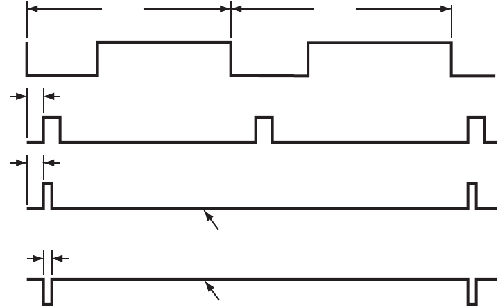
802BT/802R Video Test Generator User Guide 201
Configuring special sync for FS, LS or CS
The special sync output can provide frame sync, line sync, or composite sync signals. The
output is controlled by setting parameters of these signals through the command line
interface. The following commands are used to set the special sync signal:
•
FSPG
- Frame sync
•
PSPG
- Probe signal
•
LSPG
- Line sync
•
CSPG
- Composite sync
Note: The special sync output is disabled whenever these parameters are set to zero.
A frame pulse can be generated and output at the beginning of each frame. In the case of
interlaced video, the frame pulse is output at the beginning of the blanking interval (of the
first field) that immediately precedes the top line of active video.
To configure frame sync on the special sync output:
1. Enable the frame sync by entering the following command:
FSPG 1
The values of the other parameters (
LSPG and CSPG
) do not matter once FSPG is
enabled.
2. Set the frame pulse polarity (either 0 for low or 1 for high) by entering the following
command:
FSPP 1
FSPG=1, FSPP=0
FSPG=1, FSPP=1
FSPW (pixels)
FSPD (lines)
ActiveBlank Blank Active
Field 0 Field 1
VSPD (lines)
VID
VS
FS
FS
202 Chapter 12 Using Special Sync Output
3. Set the frame pulse pixel width (in the range from 1 pixel to
HTOT
- 1) by entering the
following command:
FSPW 100
4. Set the frame pulse delay (in the range from 0 <=
FSPD
< (
VTOT
-
FSPW
- 1) [default =
0]) by entering the following command:
FSPD 10
5. Save these settings by entering the following command:
ALLU
To configure line sync on the special sync output:
1. Enable the line sync signal by entering the following commands:
FSPG 0
PSPG 0
LSPG 1
ALLU
The value of composite sync
CSPG
does not matter once these are set.
2. Set the line sync pulse polarity by entering the following command:
LSPP 1 // 1 = high (default)
ALLU
To configure composite sync on the special sync output:
1. Enable digital composite sync by entering the following command:
SSST 2 (or 6,11)
Alternatively, you can press the DCS key on the front panel.
2. Enable the composite sync signal by entering the following commands:
FSPG 0
PSPG 0
LSPG 0
CSPG 1
ALLU
3. Set the composite sync pulse polarity by entering the following commands:
CSPP 1 // 1 = high (default)
ALLU
204 Appendix A Command Reference
Commands by name
206 Appendix A Command Reference
*DDT Delay Device Trigger
Class Trigger
Description Specifies a command or command string to be executed when the generator is “triggered”
with the *TRG command. Only one *DDT command can be pending at a time. The
command or query arguments must be enclosed in quotes.
Command syntax *DDT “command_1; command_2 ... command_n”
Example
*DDT “imgl flat; imgu”
*TRG // to invoke the command line in quotes from the *DDT command
Related commands *TRG
Video Test Generator User Guide 207
*ESE Event Status Enable
Class GPIB
Description Sets the Event Status Enable register to the given mask value. The bits in the Event Status
Enable register function as enable bits for each corresponding bit in the Event Status
register. That is, when a bit in the Event Status register goes high, and the corresponding
bit in the Event Status Enable register is a 1, it is enabled and will cause the ESB bit in the
Status Byte register to go high.
The *ESE? query returns the current value of the Event Status Enable register.
Command syntax *ESE mask
mask
0 - 255
Example *ESE 8
Query syntax *ESE?
Query response mask NL
Where mask is in integer NR1 form.
See also: *CLS, *ESR?
208 Appendix A Command Reference
*ESR? Event Status Register
Class GPIB
Description Returns the current value of the Event Status register. After this command is executed, the
Event Status register is cleared. This is the only way of clearing any bit in the Event Status
register except by the *CLS command.
Query syntax *ESR?
Returns registerValue NL
Where registerValue is in integer NR1 form.
Related commands *CLS, *ESE
Video Test Generator User Guide 209
*IDN? IDeNtification
Class GPIB
Description Returns an equipment identification string formatted per IEEE-488.2 standards.
Query syntax *IDN?
Returns Company,Model,SerialNumber,FirmwareVersion
Company
Always QuantumData.
Model
Product model description.
SerialNumber
Serial number of nonvolatile SRAM module (Dallas chip) in generator.
FirmwareVersion
Version number of currently installed firmware.
Example
R:\*idn?
QuantumData,802BT-DVI-AN,7514191,7.38380000
210 Appendix A Command Reference
*OPC OPeration Complete
Class GPIB
Description Causes the 882 to set the OPC bit in the Event Status register when all operations have
been completed. Since there are no overlapping commands, the *OPC command will set
the OPC bit immediately when executed.
The *OPC query will put a 1 in the output buffer when all operations are complete.
Command syntax *OPC
Query syntax *OPC?
Returns NL
212 Appendix A Command Reference
*SRE Service Request Enable
Class GPIB
Description Sets the Service Request Enable register to the mask value given. The bits in the Service
Request Enable register function as enable bits for each corresponding bit in the Status
Byte register to enable a condition to request service from the system controller. That is,
when a bit in the Status Byte register goes true, and the corresponding bit in the Service
Request Enable register is also true, the 882 will request service through the GPIB. The
*SRE query returns the current value of the Service Request Enable register.
Command syntax *SRE mask
mask
0 - 255
Example *SRE 16
Query syntax *SRE?
Returns mask NL
Where mask is in integer NR1 form.
Related commands *STB, *ESE
Video Test Generator User Guide 213
*STB STatus Byte
Class GPIB
Description Returns the current value of the Status Byte register. The value stored in the Status Byte
register is not affected by reading it.
Query syntax *STB?
Returns statusByte<NL>
Where statusByte is in integer NR1 form.
Related commands *SRE, *ESR?, *CLS
214 Appendix A Command Reference
*TRG TRiGger
Class GPIB port control
Description Triggers the generator programmatically. The *TRG command is used to trigger a
command or command string entered with the *TRG command.
Command syntax *TRG
Example
*DDT “imgl flat;imgu”
*TRG // Invoke the command line in quotes from the *DDT command
Related commands *DDT
Video Test Generator User Guide 215
*TST self TeST
Class GPIB port control
Definition: Causes the 882 to perform a self-test and report the results in a response message. If the
self-test fails, an ASCII "1" is placed in the output buffer; otherwise, an ASCII "0" is placed
in the output buffer.
Query syntax *TST?
Returns result<NL>
Where result is in integer NR1 form.
216 Appendix A Command Reference
*WAI WAIt for completion suffix
Class GPIB port control
Description Causes the generator to wait until all processes have been completed before sending the
prompt. Normally, the generator returns a prompt immediately after either an FMTU,
IMGU, ALLU, BOOT, INIT, or SCAL command is received, even before these commands
have finished executing. If the system controlling the generator must know when a
command has finished executing, use a semicolon to append the suffix … ;*WAI. .
Command syntax command; *WAI
command
FMTU, IMGU, ALLU, BOOT, INIT, or SCAL
Example
FMTL vga_m3 // Load a format from memory to buffer
IMGL SMPTE133 // Load the SMPTE RP-133 image to buffer
ALLU; *WAI // Update hardware to current buffer contents and delay
// prompt until all done
Video Test Generator User Guide 217
ADDR memory ADDRess
Class Direct processor control
Description Sets the pointer register that is used in connection with the PUTR command and GETR?
query. The ADDR? query returns the current contents of the pointer register.
Note: This command is used only with custom applications and command files created by
Quantum Data.
Command syntax ADDR address
address
0 to 4,294,967,295 (BASE = 10)
-2,147,483,648 to 2,147,483,647 (BASE = -10)
to FFFFFFFF (BASE = 16)
-80000000 to 7FFFFFFF (BASE = -16)
Query syntax ADDR?
Query response address
Other required
commands ADDR and ADDR? expect and return parameters formatted according to the current radix
set by the BASE command.
218 Appendix A Command Reference
ADOT draw A single pixel DOT
Class Custom image primitive
Description Draws a single pixel dot. A dot is the smallest graphic element that can be drawn. It uses
three parameters: the color and the X and Y coordinates.
Command syntax ADOT color x y
color
available colors
x
positive integer number
y
positive integer number
Other required
commands The FMTU command instructs the generator to use the new setting. The ALLU command
updates hardware to the new setting and redraws the test image.
Example
ADOT White 200 300 // Draw white dot at X = 200 Y = 300
ALLU // Update hardware to current buffer contents
220 Appendix A Command Reference
ALIN create ALIas New
Class Alias
Description Creates an alias for an object such as a format, image or test sequence. You can create
more than one alias name for an object.
Command syntax ALIN alias object
Example
ALIN MYDMTFMT DMT0675 // creates alias format for format DMT0675
Related commands Use ALIQ? to query alias names.
Use ALIK to remove an alias name.
222 Appendix A Command Reference
ALLE end ALL Editor sessions
Class Directory, format, image and sequence editor control
Description Same as entering all of the DIRE, FMTE, IMGE and SEQE commands.
Command syntax ALLE
Video Test Generator User Guide 223
ALLU ALL Use
Class System control
Description Checks the current contents of the format buffer for errors. If no errors are found, it
reconfigures the signal generating hardware in accordance with the contents. Next, the
current test image is re-rendered using the latest system and format parameter data.
Command syntax ALLU
Other required
commands This command updates the generator after using the FMTL, IMGL and SEQL commands
to load new files from memory. This command also can be used to see the results of work
when using commands to edit formats or custom images.
Example
FMTL vga_m3 // Load a format from memory to buffer
ALLU // Update hardware to current buffer contents
224 Appendix A Command Reference
AMAP
render A pixel MAP
Class Bitmap image control
Description Renders (copies) a pixel map stored in the generator as name to the frame buffer. The
bitmap will be placed so that the top left corner will be at the given x, y location in the
frame buffer.
Command syntax AMAP x y name
x, y
location
name
a valid MS-DOS filename (8 characters minus any extension)
Query syntax AMAP?
Example
AMAP 0 0 myicon // Renders a pixel map called “myicon”
// in the top left corner of active video
Video Test Generator User Guide 225
ANIG
ANalyzer Image Gate
Class DVI signal analyzer
Description Activates or deactivates the FormatRx and DeltaErr analyzer images.
Command syntax ANIG gate
gate
0 = analyzer images are not activated
1 = analyzer images are activated
Query syntax ANIG?
Query response 0 or 1
Example
ANIG 1 // activates analyzer images
IMGL FormatRx; IMGU //outputs FormatRx image
226 Appendix A Command Reference
ANIM? current test image has ANIMation
Class Image editor control
Description Returns a flag indicating if the image currently being displayed is animated.
Query syntax ANIM? imageName
Query response 0 = Not animated (static image) or the image was not found.
1 = Animated.
Example
ANIM? cubes // to determine if the “cubes” image has animation
1 // response indicates that “cubes” is an animated image
Video Test Generator User Guide 227
ANTI ANTI-alias
Class Image drawing primitives
Description Causes other primitives to be drawn using anti-aliasing on diagonal edges when
appearing anywhere in a custom image. This command affects only television formats on
801GX generators. It causes the leading and trailing edges of rectangles to have
controlled rise and fall times.
Command syntax ANTI
Other required
commands The IMGU or ALLU command must be used to redraw the custom image using
anti-aliased primitives.
228 Appendix A Command Reference
ARAT Audio sampling RATe
Class Format parameter setting - Audio signal
Description Sets the sampling rate of the audio stream output from the generator. This sets the CT
parameter of the Audio InfoFrame (as specified in EIA/CEA-861-B, table 20).
Command syntax ARAT rate
rate
192.0E3
176.4E3
96.0E3
88.2E3
48.0E3 (default)
44.1E3
32.0E3
Example
ARAT 48.0E3
IFGU
Related commands XAUD (SF parameter)
Video Test Generator User Guide 229
AROW
render A ROW of pixels
Class Bitmap image control
Description Renders (copies) binary stored as a hexstring to the frame buffer. The bitmap will be
placed so that the top left corner will be at the given x, y location in the frame buffer.
Command syntax AROW x y bpp hexstring
Query syntax AROW?
Example
AROW 5 5 4 02D // render hex data “02D” directly into frame
// buffer at location 5, 5 at a depth of
// 4 bits-per-pixel
230 Appendix A Command Reference
ASBG Analog Sync on Blue Gating
Class Format parameter setting - Analog video signal
Description Enables and disables adding composite sync to the blue analog video outputs when
analog sync is selected (see SSST command) and an analog video signal is being
generated (see AVST command). The ASBG? query returns the current setting of ASBG.
See the ASSG command description for information on simultaneously controlling red,
green and blue sync gating.
Command syntax ASBG mode
mode
0 = OFF
1 = ON
Query syntax ASBG?
Query response mode
Other required
commands The FMTU command instructs the generator to use the new setting. The ALLU command
updates hardware to the new setting and redraws the test image.
Example
ASBG 1 // Enable comp sync on blue in buffer
FMTU // Update hardware to current buffer contents
Video Test Generator User Guide 231
ASCT Analog Sync Composite Type
Class Format parameter setting - Analog video signal
Description Sets the kind of composite sync added to the analog video outputs when analog sync is
enabled (see SSST command) and an analog video signal is being generated (see AVST
command). The ASCT? query returns the current setting of ASCT. A setting of zero (0)
indicates that the ACS sync selection cannot be activated by the operator.
Command syntax ASCT type
type
0 = none
1 = American HDTV ORed
2 = American ORed
3 = American w/serr
4 = American w/serr & eq
5 = European HDTV ORed
6 = European ORed
7 = European w/serr
8 = European w/serr & eq
9 = American HDTV w/serr
10 = American HDTV w/serr & eq
11 = European HDTV w/serr
12 = European HDTV w/serr & eq
13 = Japanese HDTV ORed
14 = Japanese HDTV w/serr
15 = Japanese HDTV w/serr & eq
Query syntax ASCT?
Query response type
232 Appendix A Command Reference
Other required
commands The SSST mode must be set to 4, 5, 6, or 7 and the AVST type must be set to 1, 2 or 5 in
order for the ASCT setting to have any affect on the generator's hardware outputs. The
FMTU command instructs the generator to use the new setting. The ALLU command
updates hardware to the new setting and redraws the test image.
Example
ASCT 2 // Enable Amer ORed comp sync in buffer
SSST 4 // Enable ACS
AVST 2 // Select analog RGB as video type
FMTU // Update hardware to current buffer contents
Video Test Generator User Guide 233
ASGG Analog Sync on Green Gating
Class (Obsolete) Format parameter
Description Enables and disables adding composite sync to the green analog video outputs when
analog sync is selected (see SSST command) and an analog video signal is being
generated (see AVST command). The ASGG? query returns the current setting of ASGG.
See the ASSG command description for information on simultaneously controlling red,
green and green sync gating.
Command syntax ASGG mode
mode
0 = OFF
1 = ON
Query syntax ASGG?
Query response mode
Other required
commands The FMTU command instructs the generator to use the new setting. The ALLU command
updates hardware to the new setting and redraws the test image.
Example
ASGG 1 // Enable comp sync on green in buffer
FMTU // Update hardware to current buffer contents
234 Appendix A Command Reference
ASRG Analog Sync on Red Gating
Class (Obsolete) Format parameter
Description Enables and disables adding composite sync to the red analog video outputs when analog
sync is selected (see SSST command) and an analog video signal is being generated
(see AVST command). The ASRG? query returns the current setting of ASRG.
See the ASSG command description for information on simultaneously controlling red,
green and red sync gating.
Command syntax ASRG mode
mode
0 = OFF
1 = ON
Query syntax ASRG?
Query response mode
Other required
commands The FMTU command instructs the generator to use the new setting. The ALLU command
updates hardware to the new setting and redraws the test image.
Example
ASRG 1 // Enable comp sync on red in buffer
FMTU // Update hardware to current buffer contents
Video Test Generator User Guide 235
ASSC Analog Sync Swing Calibration factor
Class System calibration settings
Description Sets the analog video calibration (or scaling) factor that's used to adjust the level set by
ASSS. Issuing the command with a single factor sets all three analog video channels to
the same value. Issuing the command with three factors sets each of the analog video
channels to each of the given values. The actual peak-to-peak swing of the analog
composite sync signals at the output connectors equals the product of ASSS multiplied by
ASSC. The ASSC? query returns the current settings of ASSC. The default factory setting
is 1.000 for this parameter.
Note: The ASSC parameter is a system level parameter that affects the analog video
swing of all formats that are recalled. The ASSC value is retained when the generator is
powered down and back up again. Query the current setting of ASSC if you are
experiencing problems with low or missing analog composite sync levels. Reinitializing the
generator's memory restores the setting to factory default values of 1.000.
Command syntax ASSC red_factor, green_factor, blue_factor
or
ASSC common_factor
factor
min = 0.000 (floating point accepted)
max = 1.000 (floating point accepted)
Query syntax ASSC?
Query response red_factor, green_factor, blue_factor
Example
ASSC .995 .998 1.00 // Reduce red and green sync levels
FMTU // Update hardware to current buffer contents
236 Appendix A Command Reference
ASSG Analog Sync Signal Gate
Class Format parameter setting - Analog video signal
Description Enables and disables adding composite sync to all three analog video outputs when
analog sync is selected (see SSST command) and an analog video signal is being
generated (see AVST command). This command can take the place of sending all three of
the individual ASRG, ASGG, ASBG commands. The ASSG? query returns the current
settings of the ASSG?
Command syntax ASSG red_mode, green_mode, blue_mode
or
ASSG common_mode
mode
0 = OFF
1 = ON
(0, 0, 0 or 0, 1, 0 only choices on 801GC-ISA)
Query syntax ASSG?
Query response red_mode, green_mode, blue_mode
Other required
commands The SSST type must be 4, 5, 6 or 7 to output analog sync. The FMTU command instructs
the generator to use the new setting. The ALLU command updates hardware to the new
setting and redraws the test image.
Example
ASSG 0,1,0 // Enable composite sync on green in buffer
FMTU // Update hardware to current buffer contents
Video Test Generator User Guide 237
ASSS Analog Sync Signal Swing
Class Format parameter setting - Analog video signal
Description Sets the maximum peak-to-peak swing for any composite sync that is added to any of the
three analog video channels. The actual peak-to-peak swing of the analog sync signals at
the output connectors equals the product of ASSS multiplied by ASSC. The ASSS? query
returns the current setting of ASSS.
Command syntax ASSS level
level
min = 0.000 volts (floating point accepted)
max = 0.400 volts (floating point accepted)
Query syntax ASSS?
Query response level
Other required
commands One or more ASSG modes must be set to ON and the SSST type must be 4, 5, 6 or 7 to
output analog sync. The FMTU command instructs the generator to use the new setting.
The ALLU command updates hardware to the new setting and redraws the test image.
Example
ASSS 0.286 // Set sync swing to 286 mV in buffer
FMTU // Update hardware to current buffer contents
238 Appendix A Command Reference
AVCM Analog Video Calibration Method
Class System calibration setting
Description Determines how the generator tests and calibrates its analog video outputs. The AVCM?
query returns the current setting of AVCM.
Command syntax AVCM type
type
0 = Interpolate
1 = Measure Interpolate
2 = Measure Set Absolute
3 = Test Levels
Query syntax AVCM?
Query response type
Example
AVCM 1 // Select Measure Interpolate
// type of self cal
Video Test Generator User Guide 239
AVCO Analog Video COnfiguration
Class Format parameter setting - Analog video signal
Description Sets the mapping of the analog video colors to the video output connections. The AVCO?
query returns the current setting of AVCO.
Command syntax AVCO type
type
0 = RGB - R to R, G to G, B to B (Normal)
1 = RBG - R to R, B to G, G to B
2 = GRB - G to R, R to G, B to B
3 = GBR - G to R, B to G, R to B
4 = BRG - B to R, R to G, G to B
5 = BGR - B to R, G to G, R to B
Query syntax AVCO?
Query response type
Other required
commands The FMTU command instructs the generator to use the new setting. The ALLU command
updates hardware to the new setting and redraws the test image.
Example
AVCO 5 // Output blue on red chan and red on blue chan
FMTU // Update hardware to current buffer contents
240 Appendix A Command Reference
AVCS Analog Video Color subcarrier Selection
Class Format parameter setting - Analog video signal
Description Sets the color subcarrier type used for the television outputs on generator models that
have television outputs available. The AVCS? query returns the current setting of AVCS.
Command syntax AVCS type
type
0 = No subcarrier
1 = NTSC-M, 3.579545 MHz (American)
2 = NTSC-44, 4.43361875 MHz (conversion format without phase alternation)
3 = PAL, 4.43361875 MHz (with phase alternation)
4 = PAL-Nc, 3.58205625 MHz (Argentina)
Query syntax AVCS?
Query response type
Other required
commands The FMTU command instructs the generator to use the new setting. The ALLU command
updates hardware to the new setting and redraws the test image.
Example
AVCS 1 // Select standard American NTSC encoding
FMTU // Update hardware to current buffer contents
Video Test Generator User Guide 241
AVPG Analog Video Pedestal Gate
Class Format parameter setting - Analog video signal
Description Enables and disables the analog video set-up pedestal. The AVPG? query returns the
current setting of AVPG.
Command syntax AVPG mode
mode
0 = OFF
1 = ON
Query syntax AVPG?
Query response mode
Other required
commands Analog video must be enabled with the AVST command in order to output an analog video
signal. The pedestal level is set with the AVPS command. The FMTU command instructs
the generator to use the new setting. The ALLU command updates hardware to the new
setting and redraws the test image.
Example
AVPG 1 // Enable use of a black level pedestal
AVPS 7.5 // Set pedestal level to 7.5 IRE
FMTU // Update hardware to current buffer contents
242 Appendix A Command Reference
AVPS Analog Video Pedestal Swing
Class Format parameter setting - Analog video signal
Description Sets a black pedestal level between the blanking level (0.0 I.R.E.) and the peak video
level (100.0 I.R.E.). The AVPS? query returns the current setting of AVPS.
Command syntax AVPS level
level
min = 0.0 I.R.E.
max = 100.0 I.R.E.
Query syntax AVPS?
Query response level
Other required
commands AVPG must be set to ON to enable the use of the pedestal. The FMTU command instructs
the generator to use the new setting. The ALLU command updates hardware to the new
setting and redraws the test image.
Example
AVPG 1 // Enable use of a black level pedestal
AVPS 7.5 // Set pedestal level to 7.5 IRE
FMTU // Update hardware to current buffer contents
Video Test Generator User Guide 243
AVSS Analog Video Signal Swing
Class Format parameter setting - Analog video signal
Description Sets the maximum peak-to-peak swing for all three analog video channels. The actual
peak-to-peak swing of the analog video signals at the output connectors equals the
product of AVSS multiplied by AVSC. The AVSS? query returns the current setting of
AVSS.
Command syntax AVSS level
level
0.000 to 1.000 volts (floating point accepted)
Query syntax AVSS?
Query response level
Other required
commands Analog video must be enabled with the AVST command in order to output an analog video
signal. The FMTU command instructs the generator to use the new setting. The ALLU
command updates hardware to the new setting and redraws the test image.
Example 1 This example uses the AVSS command changes the output level of the NTSC format from
714mV to 500mV, and adds the revised format to the format knob list.
FMTL NTSC
FMTB
AVSS 0.5
FMTE
FMTA NTSC_1
DIRL fmt
DIRB
NAMI 1 NTSC_01
DIRE
DIRS
Example 2 This example enables analog video, and sets the video swing.
AVST 2 // Select RGB component color video in buffer
AVSS 0.714 // Set to 714 mV in buffer
FMTU // Update hardware to current buffer contents
244 Appendix A Command Reference
Example 3 This example changes the sync level from 286mV to 200mV, and sets the video output
level at 500mV.
FMTL NTSC
FMTB
ASSS 0.2
AVSS 0.7
FMTE
FMTA NTSC_1
Video Test Generator User Guide 245
AVST Analog Video Signal Type
Class Format parameter setting - Analog video signal
Description Establishes the type of signal that appears on the analog video outputs of the generator.
The AVST? query returns the current setting of AVST.
Command syntax AVST type
type
0 = none
1 = Analog Y (grayscale)
2 = Analog RGB (color)
3 = CVBS or S-Video grayscale
4 = CVBS or S-Video color
5 = Analog YPrPb (old SMPTE 240M HDTV)
6 = Analog YCrCb ITU BT.601 (ANSI/SMPTE 170M TV)
7 = Analog YPrPb SMPTE RP177 HDTV
8 = YPrPb ITU-R BT.709 HDTV
Query syntax AVST?
Query response type
Other required
commands DVST must be set to zero when analog video is used. The FMTU command instructs the
generator to use the new setting. The ALLU command updates hardware to the new
setting and redraws the test image.
Example
DVST 0 // Disable digital video
AVST 2 // Select RGB component color video
ALLU // Update hardware and redraw test image
246 Appendix A Command Reference
BALG dc BALancing Gate
Class Format parameter setting - Digital video signal
Description Enables and disables adding DC balancing to the Open LVDI digital outputs on generators
that support LVDI outputs. FPD-Link compatible displays use unbalanced (BALG 0), while
OpenLDI displays use balanced (BALG 1).
The BALG? query returns the current setting of BALG.
Command syntax BALG mode
mode
0 = OFF
1 = ON
Query syntax BALG?
Query response
mode
Other required
commands FMTU or ALLU
Video Test Generator User Guide 247
BASE number BASE
Class Direct processor control
Description Establishes the radix of address and data parameters passed to or returned from the
ADDR, GETA, GETR, PUTA, PUTR, and CALL commands. If a negative radix is specified,
then parameters passed to (or returned from) these functions are assumed to be signed.
For example, if BASE= -16, then the value -1 communicates the value FFFFFFFF hex.
The BASE? query returns the current setting of BASE. The radix radix always is passed
and returned in base 10, regardless of the setting of BASE. BASE is preset to -10 each
time the generator is powered on. Base -10 is the preferred radix. The BASE? query
returns the current setting of BASE.
Note: This command is used only with custom applications and command files created by
Quantum Data.
Command syntax BASE radix
radix
-36 to -2 or 2 to 36
Query syntax BASE?
Query response radix
248 Appendix A Command Reference
BLUG BLUe Gate
Class Video Gate
Description Toggles the blue video signal gate.
Command syntax BLUG mode
mode
0 disable
1 enable
Query syntax BLUG?
Query response 0 or 1
Other required
commands ALLU to invoke the command.
Related commands GRNG, REDG
Example
BLUG 0; ALLU // disable blue video component
Video Test Generator User Guide 249
BOIT BOot and IniTialize
Class System control
Description Initializes the generator without going through a self-calibration.
Command syntax BOIT
250 Appendix A Command Reference
BOOT warm BOOT
Class System control
Description Causes the generator to go through its standard power-up procedure. Self-calibration is
not performed. The procedure checks all RAM storage locations for corrupt data. This
command is equivalent to turning the generator off and then on.
Command syntax BOOT
Video Test Generator User Guide 251
BRAT Bit RATe
Class Format parameter setting - Digital audio signal
Description Sets the bit rate (in Hz) for an external compressed audio source. This sets the MBR
parameter of the Audio InfoFrame (as specified in EIA/CEA-861-B).
The BRAT? query returns the current compressed digital audio bit rate
Command syntax BRAT rate
rate
0.0 (audio is not compressed)
8000, 16000, 24000 (or higher multiple of 8,000)
Query syntax BRAT?
Example
BRAT 32000
IFGU
Related commands XAUD (MBR parameter)
252 Appendix A Command Reference
CACH
instruction CACHe enable
Class System parameter settings
Description Enables and disables the use of the instruction cache. The CACH? query returns the
current setting of CACH.
Command syntax CACH mode
mode
0 = OFF
1 = ON
Query syntax CACH?
Query response 0 or 1
Example
CACH 0 // Disable the use of the instruction cache
Video Test Generator User Guide 253
CALF analog video CALibration Factors
Class System calibration settings
Description Sets the analog output calibration factors to values other than those set by the generator's
own self-calibration function. Each channel is calibrated using two independent zero
calibration points, and two independent slope calibration points. Interpolation equations for
the different video types are used to set the caldac values that controls the output sync
and voltage levels to the correct values.
TV calibration uses two factors for NTSC output, and two factors for PAL output.
Note: Sending bad calibration factors to the generator via the CALF command can hang
the generator. If the generator hangs it will have to be reinitialized.
Command syntax CALF zero500R, zero50R, slope1500R, slope1000R, zero500G, zero50G, slope1500G,
slope1000R, zero500B, zero50B, slope1500B, slope1000B, ntsc714, pal700, ntsc_blank,
pal_blank
zero500R
Red calibration factor from 0 (most negative) to 4095 (least negative) at -1.0V.
zero50R
Red calibration factor from 0 (most negative) to 4095 (least negative) at -100mV.
slope1500R
Red calibration factor from 0 (maximum swing) to 4095 (minimum swing) at 2.0V.
slope1000R
Red calibration factor from 0 (maximum swing) to 4095 (minimum swing) at 1.4V.
zero500G, zero50G, slope1500G, slope1000R
Green calibration factors.
zero500B, zero50B, slope1500B, slope1000B
Blue calibration factors.
ntsc714
Factor from 0 (maximum swing) to 4095 (minimum swing) for NTSC output level at
714mV. The ntsc714 and ntsc_blank values are interrelated.
pal700
Factor from 0 (maximum swing) to 4095 (minimum swing) for PAL output level at
700mV.
ntsc_blank
Factor from 0 (least negative) to 4095 (most negative) used to set the zero level of the
NTSC output at 0.0 IRE.
254 Appendix A Command Reference
pal_blank
Factor from 0 (least negative) to 4095 (most negative) used to set the zero level of the
PAL output at 0.0 IRE.
Query syntax CALF?
Related commands The AVSC command matches the levels for the three analog video channels. The ALLU
command updates the signal generating hardware to the new settings and redraws the
test image.
Example
CALF 1090, 2590, 1992, 3223, 1149, 2634, 2059, 3278, 1001, 2506, 1993,
3221, 781, 780, 3387, 3513 // Set new factors
ALLU // Use new factors
Video Test Generator User Guide 255
CALL CALL internal function
Class Direct processor control
Description Calls internal C functions. Address address is the entry point of the C function to be called.
Parameter passed indicates the number of parameters to be passed. If passed is not zero,
then parameters being passed p(1) through p(n) immediately follow the passed parameter
on the command line.
The CALL? query is similar to the CALL command except that returned parameters are
expected. Here, a third parameter returned is added to indicate the number of parameters
returned by the function. If BASE= -10 or -16 and a returned value of -1 is given
(4,294,967,295 if BASE=10 or FFFFFFFF if BASE=16), then a single value is read from
register A8 of the TMS34010 (rather than being popped off the C stack). Most C functions
that return a single parameter return their single parameter in this way. Returned
parameters are space-delimited and formatted according to the current radix (see BASE
command). All parameters passed to the CALL and CALL? must be formatted according
to the current radix. This includes the parameters passed and returned.
Note: This command is used only with custom applications and command files created by
Quantum Data. Indiscriminate use of this command can cause the generator to stop
operating or loss of stored data in non-volatile RAM.
Command syntax CALL address passed [ p(1) [ p(2) [ p(3) …[ p(18) ]…]]]
address
0 to 4,294,967,295 (BASE = 10)
-2,147,483,648 to 2,147,483,647 (BASE = -10)
0 to FFFFFFFF (BASE = 16)
-80000000 to 7FFFFFFF (BASE = -16)
passed
0 to 18 (BASE = -10 or 10)
0 to 12 (BASE = -16 or 16)
p(n)
0 to 4,294,967,295 (BASE = 10)
-2,147,483,648 to 2,147,483,647 (BASE = -10)
0 to FFFFFFFF (BASE = 16)
-80000000 to 7FFFFFFF (BASE = -16)
Query syntax CALL? address passed returned [ p(1) [ p(2) [ p(3) …[ p(17) ]…]]]
256 Appendix A Command Reference
address
0 to 4,294,967,295 (BASE = 10)
-2,147,483,648 to 2,147,483,647 (BASE = -10)
0 to FFFFFFFF (BASE = 16)
-80000000 to 7FFFFFFF (BASE = -16)
passed
0 to 18 (BASE = -10 or 10)
0 to 12 (BASE = -16 or 16)
returned
4,294,967,295 and 0 to 20 (BASE = 10)
-1 to 20 (BASE = -10)
FFFFFFFF and 0 to 14 (BASE = 16)
-1 to 14 (BASE = -16 query only)
p(n)
0 to 4,294,967,295 (BASE = 10)
-2,147,483,648 to 2,147,483,647 (BASE = -10)
0 to FFFFFFFF (BASE = 16)
-80000000 to 7FFFFFFF (BASE = -16)
Query response ret(1) [ ret(2) [ ret(3) … [ ret(20) ]…]]
Other required
commands CALL and CALL? expect and return parameters formatted according to the current radix
set by the BASE command.
Video Test Generator User Guide 257
CENT draw video CENTering markers
Class Custom image primitive
Description Draws a small cross in the center of active video. If the format has an even number of
active pixels, the vertical line is 2 pixels thick. The horizontal line is 2 pixels thick if the
format has an even number of active lines. The primitive uses a single parameter, the
color of the cross.
Command syntax CENT color
color
available colors
Other required
commands The FMTU command instructs the generator to use the new setting. The ALLU command
updates hardware to the new setting and redraws the test image.
Example
CENT red // Draw a small red cross in center of active video
ALLU // Update hardware to current buffer contents
258 Appendix A Command Reference
CROS draw a centered CROSs
Class Custom image primitive
Description Draws a large centered cross that fills the active video area. The vertical line is 2 pixels
thick if the format has an even number of active pixels. The horizontal line is 2 pixels thick
if the format has an even number of active lines. The primitive uses a single parameter,
the color of the cross.
Command syntax CROS color
color
available colors
Other required
commands The FMTU command instructs the generator to use the new setting. The ALLU command
updates hardware to the new setting and redraws the test image.
Example
CROS magenta // Draw a large cross in the center of the active video
ALLU // Update hardware to current buffer contents
Video Test Generator User Guide 259
CSPG Composite Sync Pulse Gate
Class Format parameter setting - Synchronization
Description Enables and disables all of the digital composite sync outputs when digital composite sync
is selected via the SSST command (SSST = 3). The CSPG? query returns the current
setting of CSPG.
Command syntax CSPG mode
mode
0 = OFF
1 = ON
Query syntax CSPG?
Query response 0 or 1
Other required
commands In order to use digital composite sync, it must be selected with the SSST command. The
FMTU command instructs the generator to use the new setting. The ALLU command
updates hardware to the new setting and redraws the test image.
Example
CSPG 1 // Enable dig comp sync in buffer
SSST 2 // Choose digital comp sync type in buffer
FMTU // Update hardware to current buffer contents
260 Appendix A Command Reference
CSPP Composite Sync Pulse Polarity
Class Format parameter setting - Synchronization
Description Establishes the logic sense of the digital composite sync output. The CSPP? query returns
the current setting of CSPP.
Command syntax CSPP polarity
polarity
0 = active-low (negative going pulse)
1 = active-high (positive going pulse)
Query syntax CSPP?
Query response 0 or 1
Other required
commands In order to use digital composite sync, it must be gated on with the CSPG command and
selected with the SSST command. The FMTU command instructs the generator to use the
new setting. The ALLU command updates hardware to the new setting and redraws the
test image.
Example
CSPG 1 // Enable dig comp sync in buffer
CSPP 1 // Select active hi in buffer
SSST 2 // Choose digital comp sync type in buffer
FMTU // Update hardware to current buffer contents
Video Test Generator User Guide 261
CTLM ConTroL Mask
Class Format parameter setting - Digital video signal
Description Sets the masked control bits for the LVDS output. The control bits are not always required
by receivers. There are two bits that can be set: CTL00 and CTL01.
Command syntax CTLM mask
mask
0 = sets bit low
1 = sets bit high
Query syntax CTLM?
Example
CTLM 2 // the 2 in hex sets the CTL01 bit to 1.
CTLM 3 // the 3in hex ets the CTL00 and CTL01 bits to 1.
Related commands RCTL

262 Appendix A Command Reference
CXAR Content Aspect Ratio
Class Format parameter setting - HDMI Active Video
Description Sets the aspect ratio of the source image content.
Command syntax CXAR aspect_ratio
aspect_ratio
0.75 to ˜2.39
The following table provides a listing of established aspect ratios.
Aspect Ratio Symbol Description Examples
0.750 OT or T90 Television Portrait 3x4, 480x640, 600x800, 768x1024,
960x1280, 1200x1600
0.800 OG or G90 Workstation Graphics
Portrait 4x5, 1024x1280, 1280x1600
1.000 Q Quadrate, "Square” 1x1, 512x512, 1024x1024
1.250 G Workstation Graphics 5x4, 1280x1024, 1600x1280
1.333… T (A)1
1. The letters in parenthesis are the letters that we used to use, before we updated our aspect ratio symbols for compatibiliity
with existing film industry standards (i.e. the symbols defined in SMPTE RP40).
SDTV / Silent Film 4x3, 640x480, 800x600, 1024x768,
1280x960, 1600x1200
˜1.37 C (B)1Academy2 “Classic”
with sound
2. In 1932, the shape of film was changed from 1.33:1 to 1.37:1 in order to better accommodate the new optical soundtrack that
was added a few years earlier. This slightly wider shape is the true aspect ratio of “classic” film. The aperture is commonly
referred to as “Academy” and was the shape of the vast majority of U.S. films produced until the 1950s.
˜4x3, 0.825x0.602 SMPTE RP40 35mm "C"
1.444… I IMAX™ 13x9, IMAX™
1.500 V (T)1Vista Vision™ 3x2, 1152x768 Apple Computer
(uncropped) Vista Vision™
1.555… M (V)1Mid 14x9, AFD Shoot and Protect (half-way
between 4x3 and 16x9)
1.600 D 16 Decimal 16x10, 1728x1080, 1280x800, see VESA
CVT 1.0
1.666… E European Film, "1.66 5x3, 1200x720, 1280x768, 1800x1080
1.750 Z Old Film 7x4, Old Metro-Goldwyn-Mayer and Disney
Films
1.777… H HDTV 16x9, 1280x720,1920x1080
˜1.85 A (F)1Film Standard (USA) ˜13x7, 1280x692, 1920x1038, 0.825x0.446
SMPTE RP40 35mm "A"
2.000 U Univisum™ 2x1, 1280x640, 1920x960
˜2.20 F (M)1“Flat”, MPEG "20x9” "˜11x5, 1280x582, 1920x874, 1.912x0.870
SMPTE RP91 70mm
˜2.39 B (C)1Anamorphic Cinema,
“2.35”3
3. Sometimes called “2.35”, which was the aspect ratio before it was changed to 2.39:1 in 1971 to keep splices from showing up
in the projected image.
˜12x5, 1280x536, 1920x804, 1.650x0.690
SMPTE RP40 35mm "B"

264 Appendix A Command Reference
DACA Digital Audio Channels Available
Class Format parameter setting - Audio signal
Description Specifies which audio channels are active.
Command syntax DACA mask
mask
0 to 3, based on following table.
Normally, each type of audio content is assigned to a particular channel and is always
output on that channel when present. There is one exception to this rule: rear center (RC)
content is switched from channel 5 to 7 whenever rear left (RL) content is simultaneously
present. To simplify this, RC content is thus treated as if it were two different types of
content: RC5 and RC7. When RL content is not present, RC content is output on channel
5 as RC5 content. When RL content is present, RC content is output on channel 7 as RC7
content.
Setting DACA will automatically set DAXA and XAUD:CA parameters to a corresponding
value (see table below).
Note: If DACA is set to a value not found in the table above, then other parameters will not
be automatically set and an error will be generated if the format is loaded while this
condition exists.
mask
0 to 255 (based on the value in the table below).Notes:
• Setting DACA will automatically set DAXA and XAUD:CA parameters to a
corresponding value (see table below). However, in the case of DACA values 243, 247,
251, and 255, two sets of DAXA and XAUD:CA values are possible. In this case, DAXA
and XAUD:CA settings will be based on those highlighted (in grey) in the table.
• If DACA is set to a value not found in the table above, then other parameters will not
be automatically set and an error will be generated if the format is loaded while this
condition exists.
Channel 1 2
Bit 0 1
Value 1 2
DACA 3
DAXA 3
XAUD:CA 0

266 Appendix A Command Reference
DACG Digital Audio Channel Gate
Class Format parameter setting - Audio signal
Description Specifies which audio channels are gated (on).
Command syntax DACG mask
mask
0 to 3 (based on the value in the table below).
Example
DACA 3 //specifies audio channels 1 and 2
DACG 3 //gates audio channels 1 and 2
FMTU
Related commands DACA
Channel 1 2
Bit 0 1
Value 1 2
Video Test Generator User Guide 267
DADG Digital Audio Down-mix Gate
Class Format parameter setting - Audio signal
Description Enables or disables downmixing of an audio signal. This sets the DM_I parameter of the
Audio InfoFrame (as specified in EIA/CEA-861-B, table 24).
Command syntax DADG mode
mode
1 = enable
0 = disable
Example
DADG 1
FMTU
IFGU
Related commands XAUD (DMI parameter), DALS
268 Appendix A Command Reference
DALS Digital Audio Level Shift Value
Class Format parameter setting - Audio signal
Description Sets the level shift value (in decibels) for downmixing of the audio signal. This sets the
LSV parameter of the Audio InfoFrame (as specified in EIA/CEA-861-B, table 23).
Command syntax DALS x
x
0 - 15 (dB)
Example
DALS 5
FMTU
IFGU
Related commands XAUD (LSV parameter), DADG
Video Test Generator User Guide 269
DASI Digital Audio Signal Interface
Class Format parameter setting - Audio signal
Description Sets the digital audio signal interface.
Command syntax DASI interface
interface
0 = none
1 = SPDIF
Example
DASI 1
IFGU
270 Appendix A Command Reference
DAST Digital Audio Signal Type
Class Format parameter setting - Audio signal
Description Sets the digital audio signal type for an audio signal. This sets the CT parameter of the
Audio InfoFrame (as specified in EIA/CEA-861-B, table 19).
Command syntax DAST type
type
0 = void
1 = IEC 60958-3 Consumer LPCM
Example
DAST 1
IFGU
Related commands XAUD (CT parameter)

Video Test Generator User Guide 271
DAXA Digital Audio Content Available
Class Format parameter setting - Audio signal
Description Specifies which speaker locations are available (present).
Command syntax DAXA mask
mask
0 to 3 (based on the value in the table below).
Normally, each type of audio content is assigned to a particular channel and is always
output on that channel when present. There is one exception to this rule: rear center (RC)
content is switched from channel 5 to 7 whenever rear left (RL) content is simultaneously
present. To simplify this, RC content is thus treated as if it were two different types of
content: RC5 and RC7. When RL content is not present, RC content is output on channel
5 as RC5 content. When RL content is present, RC content is output on channel 7 as RC7
content.
Setting DAXA will automatically set DACA and XAUD:CA parameters to a corresponding
value (see table below). However, this method should not be used to gate channels.
Instead, DAXG should be used after all of the available channels have been selected.
Note: If DAXA is set to a value not found in the table above, then other parameters will not
be automatically set and an error will be generated if the format is loaded while this
condition exists.
Example
DAXA 3 //specifies FR and FL as having audio content
DAXG 3 //gates FR and FL content
FMTU
Related commands DAXG
Content FR FL
Bit 1 0
Value 2 1
DAXA 3
DACA 3
XAUD:CA 0

272 Appendix A Command Reference
DAXG Digital Audio Content Gate
Class Format parameter setting - Audio signal
Description Specifies which speaker locations are gated (on).
Command syntax DAXG mask
mask
0 to 3 (based on the value in the table below).
Example
DAXA 3 //specifies FR and FL as having audio content
DAXG 3 //gates FR and FL content
FMTU
Related commands DAXA
Content FR FL
Bit 1 0
Value 2 1
Video Test Generator User Guide 273
DCBM Display Code Bit Mask
Class Direct processor control
Description Sets the 4-bit binary bit mask used by the DCRD? query. The mask is entered as the
decimal equivalent of a 4-bit binary number. The binary number represents the masking of
the individual sense lines from M3 (MSB) to M0 (LSB). The DCBM? query returns the
current setting of DCBM.
Command syntax DCBM mask
mask
0 = 0 0 0 0 8 = 1 0 0 0
1 = 0 0 0 1 9 = 1 0 0 1
2 = 0 0 1 0 10 = 1 0 1 0
3 = 0 0 1 1 11 = 1 0 1 1
4 = 0 1 0 0 12 = 1 1 0 0
5 = 0 1 0 1 13 = 1 1 0 1
6 = 0 1 1 0 14 = 1 1 1 0
7 = 0 1 1 1 15 = 1 1 1 1
Query syntax DCBM?
Query response mask
Other required
commands The FMTU command instructs the generator to use the new setting. The ALLU command
updates hardware to the new setting and redraws the test image.
Example
DCBM 7 // Set mask to read sense lines 0, 1 and 2 only
FMTU // Update hardware to current buffer contents
274 Appendix A Command Reference
DCEX Display Code EXpected
Class Format parameter settings
Description Sets up the display code that is expected from a display connected to the generator. The
code is determined by one or more sense lines being connected to ground by the display.
Many video controller cards for the Apple Macintosh II and VGA type cards for the IBM-PC
sample the status of the display code sense lines. The information then sets up one of
several different operating modes to match a particular display. An improper display code
may make the controller card or display appear to malfunction.
The DCEX? query first performs a logical AND operation with the display code bit mask
and the actual display code that's sensed. The decimal equivalent of the result then is
returned. The mask is set with the DCEX command.
The expected setting and the actual result are both shown in the Format test image. They
have no effect how a given format generates a set of test signals.
Command syntax DCEX code
code
0 = 0 0 0 0 8 = 1 0 0 0
1 = 0 0 0 1 9 = 1 0 0 1
2 = 0 0 1 0 10 = 1 0 1 0
3 = 0 0 1 1 11 = 1 0 1 1
4 = 0 1 0 0 12 = 1 1 0 0
5 = 0 1 0 1 13 = 1 1 0 1
6 = 0 1 1 0 14 = 1 1 1 0
7 = 0 1 1 1 15 = 1 1 1 1
Query syntax DCEX?
Query response code
Other required
commands The FMTU command instructs the generator to use the new setting. The ALLU command
updates hardware to the new setting and redraws the test image.
Example
DCBM 7 // Set mask to read sense lines 0, 1 and 2 only
DCEX 5 // Only lines 0 and 1 should be grounded
FMTU // Update hardware to current buffer contents
Video Test Generator User Guide 277
DCRD? Display Code ReaD
Class Direct processor control
Description Returns the display code detected on the monitor sense lines as filtered through the
display code bit mask. Converting the returned decimal number to a 4-bit binary number
shows the status of the individual sense lines from M3 (MSB) to M0 (LSB).
Query syntax DCRD?
Query response code
code
0 = 0 0 0 0 8 = 1 0 0 0
1 = 0 0 0 1 9 = 1 0 0 1
2 = 0 0 1 0 10 = 1 0 1 0
3 = 0 0 1 1 11 = 1 0 1 1
4 = 0 1 0 0 12 = 1 1 0 0
5 = 0 1 0 1 13 = 1 1 0 1
6 = 0 1 1 0 14 = 1 1 1 0
7 = 0 1 1 1 15 = 1 1 1 1
Other required
commands DCBM sets the mask used for reading the display code.
Example
DCRD? // Return current sense lines reading
278 Appendix A Command Reference
DDCV? DDC Version supported
Class EDID and DDC control
Description The DDCV? query returns a status flag indicating if the generator hardware supports
VESA DDC communications.
Query syntax DDCV?
Query response 0 or 1
0 = no DDC support
1 = DDC supported
Example
DDCV? // Return DDC support information
Video Test Generator User Guide 279
DELX slider image DELta X
Class Image editor control
Description Sets the amount of horizontal shift that occurs for each step of the SlideG and SlideRGB
built-in images. The command is also used to set the horizontal size of the white patch
used in the Regulate image. The DELX? Query returns the current DELX setting.
Command syntax DELX delta_x
delta_x
horizontal distance in pixels
Query syntax DELX?
Query response
delta_x
Example
DELX 8 // Set H shift to 8 pixels per step
DELY 3 // Set V shift to 3 pixels per step
DWEL 2 // Display each step for 2 frames
IMGL “SlideG” // Select Image that uses DELX and DELY
IMGU // Draw the Image
280 Appendix A Command Reference
DELY slider image DELta Y
Class Image editor control
Description Sets the amount of vertical shift that occurs for each step of the SlideG and SlideRGB
built-in images. The command is also used to set the vertical size of the white patch used
in the Regulate image. The DELY? Query returns the current DELY setting.
Command syntax DELY delta_y
delta_y
vertical distance in pixels
Query syntax DELY?
Query response delta_y
Example
DELX 8 // Set H shift to 8 pixels per step
DELY 3 // Set V shift to 3 pixels per step
DWEL 2 // Display each step for 2 frames
IMGL “SlideG” // Select Image that uses DELX and DELY
IMGU // Draw the Image
Description Updates hardware with new EDID contents.
Command syntax DIDU
Example
XDID 8 3 DE33FF
DIDU
Related commands XDID
Video Test Generator User Guide 281
DIRA DIRectory save As
Class Directory memory management
Description Saves the current contents of the directory edit buffer using the given name.
Command syntax DIRA name
name
a valid MS-DOS filename (8 characters minus any extension)
Example
DIRA MY_DIR // Save with the name "MY_DIR"
282 Appendix A Command Reference
DIRB DIRectory editing Begin
Class Directory memory management
Description Marks the beginning of a directory editing session. This command does nothing in the
current firmware version, but is used for compatibility with future versions of firmware.
Command syntax DIRB
Other required
commands Use either a DIRL command to load an existing directory or a DIRN command to create a
new directory. Use DIRE when ending the editing session.
Example
DIRN // Initialize directory edit buffer
DIRB // Start directory editing session
// One or more directory editing commands ...
DIRE // End directory editing session
Video Test Generator User Guide 283
DIRE DIRectory editing End
Class Directory memory management
Description Marks the end of a directory editing session. This command does nothing in the current
firmware version, but is used for compatibility with future versions of firmware.
Command syntax DIRE
Other required
commands Use DIRB when starting the editing session. Use EDID and DDC controlDIRA or DIRS to
save changes.
Example
DIRB // Start directory editing session
// One or more directory editing commands ...
DIRA MYDIR_02 // Save edited directory as MYDIR_02
DIRE // End directory editing session
284 Appendix A Command Reference
DIRK DIRectory Kill
Class Directory memory management
Description Deletes a directory by name. The query returns a one if the named directory can be
deleted. If directory is read-only or nonexistent, the query returns a zero.
Command syntax DIRK name
name
a valid MS-DOS filename (8 characters minus any extension)
Query syntax DIRK? name
name
a valid MS-DOS filename (8 characters minus any extension)
Query response 0 or 1
Example
DIRK MY_DIR // Delete directory called "MY_DIR"
Video Test Generator User Guide 285
DIRL DIRectory Load
Class Directory memory management
Description Copies the directory having a name equal to name from directory memory into the
directory edit buffer. The query returns a one if the named directory can be loaded;
otherwise, a zero is returned.
Note: Use the FMTP, IMGP and SEQP commands to select which directory is used for the
format, image, and sequence selection lists.
Command syntax DIRL name
name
a valid MS-DOS filename (8 characters minus any extension)
Query syntax DIRL? name
name
a valid MS-DOS filename (8 characters minus any extension)
Query response 0 or 1
Example
DIRL MY_DIR // Load "MY_DIR" directory in edit buffer
286 Appendix A Command Reference
DIRN DIRectory New
Class Directory memory management
Description Initializes the directory edit buffer. The name name is assigned as the directory's name.
The query will return the name that has been assigned as the directory's name.
Command syntax DIRN name
name
optional valid MS-DOS filename (8 characters minus any extension)
Query syntax DIRN?
Example
DIRN // Init edit buffer without assigning a new name
or
DIRN MY_DIR // Init edit buffer with name of "MY_DIR"
Video Test Generator User Guide 287
DIRP DIRectory Path
Class Directory memory management
Description Sets the current directory path name. The query will return the current directory path
name.
Command syntax DIRP name
name
a valid MS-DOS filename (8 characters minus any extension)
Query syntax DIRP?
Query response name
Example
DIRP DIRPTH01 // Set directory path to DIRPTH01
288 Appendix A Command Reference
DIRQ? DIRectory Query pointer
Class Directory memory management
Description Returns the number directory names from the list of all the directory names stored in
directory memory beginning at index. The directories are kept in alphanumeric order.
Query syntax DIRQ? index number
index
positive integer number
number
positive integer number
Query response List of specified directory names
Example
DIRQ? 1 5 // List the first five directories in memory
or
DIRQ? 1 9999 // List all directories in memory
Video Test Generator User Guide 289
DIRS DIRectory Save
Class Directory memory management
Description Saves the current directory edit buffer contents into directory memory using the current
name of the directory in the edit buffer.
Example
DIRN fmtnew // creates a new format directory (knob list) name
DIRB // begins a directory editing session
NAMI 1 myfmt1 // adds myfmt1 to directory (knob list)
.
. // add other formats to directory (knob list)
.
NAMI n myfmtn // adds myfmtn to directory (knob list)
DIRE // ends the directory editing session
DIRS // saves the directory
290 Appendix A Command Reference
DMAP
Dimension bitMAP
Class Bitmap image control
Description Defines the size of a rectangular bitmap array in the edit buffer. The width and height, in
pixels is set by the width and height parameters. The number of data bits per pixel is set
by the bpp parameter.
Command syntax DMAP width height bpp
width
min =
max =
height
min =
max =
bpp
1, 2 or 4
Query syntax DMAP?
Query response width height bpp
Example
DMAP 32 20 4 // Set bitmap array to 32 pixels wide by 20 pixels high
// and a depth of 4 bits-per-pixel
Video Test Generator User Guide 291
DNUM Display sequence step NUMbers
Class Sequence editor commands
Description Enables and disables the addition of the sequence step number to the displayed test
image when running a sequence.
Command syntax DNUM mode
mode
0, 1 or 2
Query syntax DNUM?
Query response mode
Example
DNUM 1 // Enable the displaying of the sequence step #
292 Appendix A Command Reference
DPGU Data Island Packet Generator Use
Class Data packet generator
Description Updates the hardware with content of the current Data Island packet.
Command syntax DPGU
Related Commands DPTG
Example 1 Turn mute on:
XGCP 1 0
DPTG 7
DPTR 1
DPGU
Example 2 Read mute status:
R:MUTE?
R:1
Example 3 Turn mute off:
XGCP 0 1
DPTG 7
DPTR 1
DPGU
Example 4 Read mute status:
R:MUTE?
R:0
Example 5 Change the N value to 6000, and let hardware determine CTS value:
XACR 6000
DTPG 7
DPGU
// You can read N and CTS value at the reciever for verification.
Example 6 Change the N value to 6000, and CTS to 8000:
XACR 6000 8000
DTPG 7
DPGU
// You can read N and CTS value at the reciever for verification.
Video Test Generator User Guide 293
Example 7 Turn audio off:
DPTG 3
DPGU
Example 8 Turn audio on:
DPTG 7
DPGU
294 Appendix A Command Reference
DPTG Data Island Packet Type Gate
Class Data packet generator
Description Gates on or off the assigned packet type (Audio Sample, Audio Clock Regeneration, or
General Control Packet) to be updated by the hardware and sent to the receiver.
Gating Audio Sample packets on and off also enables and disables the audio output from
the transmitter. The mask value is a value ORed with the current setting.
Command syntax DPTG mask
mask
1 = General Control Packet (GCP)
2 = Audio Clock Regeneration (ACR)
4 = Audio Sample
8 = Generic Data Packet (GDP)
Related commands DPGU, DPTR
Example This example gates off the audio (the current value is 7):
DPTG 3; DPGU
See DPGU for other examples.
Video Test Generator User Guide 295
DPTR Data Island Packet Type Repeat Mask
Class Data packet generator
Description Specifies if a General Control packet is sent with every frame or sent once.
Note: Audio Sample and ACR packets are always enabled (and thus cannot be changed).
Command syntax DPTR mask
mask
1 = General Control Packet (GCP)
8 = Generic Data Packet (GDP)
Example See DPGU for examples.
296 Appendix A Command Reference
DSCT Digital Sync Composite Type
Class Format parameter setting - Digital video signal
Description Establishes the type of composite sync that appears at the digital composite sync outputs
when digital composite sync is selected via the SSST command. The DSCT? query
returns the current setting of DSCT. A setting of zero (0) indicates that digital composite
sync cannot be activated by the operator.
Command syntax DSCT type
type
0 = none
10 = American HDTV w/serr & eq
11 = European HDTV w/serr
12 = European HDTV w/serr & eq
13 = Japanese HDTV ORed
14 = Japanese HDTV w/serr
15 = Japanese HDTV w/serr & eq
Query syntax DSCT?
Query response type
Other required
commands The FMTU command instructs the generator to use the new setting. The ALLU command
updates hardware to the new setting and redraws the test image.
Example
DSCT 2 // Select simple Amer ORed in buffer
FMTU // Update hardware to current buffer contents
Video Test Generator User Guide 297
DSST Digital Sync Separate Type
Class Format parameter setting - Digital video signal
Description Establishes the type of digital separate sync that appears at the digital HS and VS outputs
of the generator when digital composite sync is selected via the SSST command and the
outputs are gated on via the HSPG and VSPG commands. The only difference between
EIA and CCIR digital separate syncs is that, in the case of CCIR, the width of the vertical
sync pulse is 0.5 line shorter than the width specified via the VSPW command. In the EIA
case, the width of the vertical sync pulse is as programmed.
After sending the DSST command, send the FMTU or ALLU command.
Command syntax DSST type
type
0 = none
1 = American separate
2 = American HDTV separate
3 = European HDTV separate
4 = Japanese HDTV separate
5 = European separate
Query syntax DSST?
Query response Returns the current setting of DSST. A setting of zero (0) indicates that separate digital
H&V sync cannot be activated by the operator.
Example
DSST 1
FMTU // Update hardware to current buffer contents

298 Appendix A Command Reference
DVIC Digital Video Identification Code
Class InfoFrame Generator (IFG) parameter
Description Writes the specified Video Identification Code (VIC) into the AVI InfoFrame.
Command syntax DVIC code
code
0 = unestablished format
1 - 34 = DVIC code corresponding to a format defined in EIA/CEA-861-B standard
(Section 4). See table below for DVIC codes.
Note: For detailed information about these timings, refer to the Quantum Data Web site at:
http://www.quantumdata.com/support/downloads/802bt/hdmi/TimingsEIA-861-B.pdf.
DVIC Format Name NCPP1SXAR2SXEX2CXAR2TUNE3HRES4VTOT5
1 DMT0659 1 A N0A 1 640 525
1 DMT0660 1 A N0A 0 640 525
2 480p59 1 A N0A 1 720 525
2 480p60 1 A N0A 0 720 525
2 480p59LH 1 A Lcbb H 1 720 525
2 480p60LH 1 A Lcbb H 0 720 525
3 480p59SH 1 A S H 1 720 525
3 480p60SH 1 A S H 0 720 525
4 720p59 1 H N0H 1 1280 750
4 720p60 1 H N0H 0 1280 750
5 1080i29 1 H N0H 1 1920 1125
5 1080i30 1 H N0H 0 1920 1125
6 480i2x29 2 A N0A 1 720 525
6 480i2x30 2 A N0A 0 720 525
6 480i2xL1 2 A Lcbb H 1 720 525
6 480i2xL2 2 A Lcbb H 0 720 525
7 480i2xS1 2 A S H 1 720 525
7 480i2xS2 2 A S H 0 720 525
8 240p2x_1 2 A N0A 1 720 262
8 240p2x_2 2 A N0A 0 720 262
8 240p2x_3 2 A N0A 1 720 263
8 240p2x_4 2 A N0A 0 720 263
8 240p2xL1 2 A Lcbb H 1 720 262
8 240p2xL2 2 A Lcbb H 0 720 262
8 240p2xL3 2 A Lcbb H 1 720 263
8 240p2xL4 2 A Lcbb H 0 720 263
9 240p2xS1 2 A S H 1 720 262
9 240p2xS2 2 A S H 0 720 262
9 240p2xS3 2 A S H 1 720 263
9 240p2xS4 2 A S H 0 720 263
10 480i4x29 1 A N0A 1 2880 525

Video Test Generator User Guide 299
10 480i4x30 1 A N0A 0 2880 525
10 480i4xL1 1 A Lcbb H 1 2880 525
10 480i4xL2 1 A Lcbb H 0 2880 525
11 480i4xS1 1 A S H 1 2880 525
11 480i4xS2 1 A S H 0 2880 525
12 240p4x_1 1 A N0A 1 2880 262
12 240p4x_2 1 A N0A 0 2880 262
12 240p4x_3 1 A N0A 1 2880 263
12 240p4x_4 1 A N0A 0 2880 263
12 240p4xL1 1 A Lcbb H 1 2880 262
12 240p4xL2 1 A Lcbb H 0 2880 262
12 240p4xL3 1 A Lcbb H 1 2880 263
12 240p4xL4 1 A Lcbb H 0 2880 263
13 240p4xS1 1 A S H 1 2880 262
13 240p4xS2 1 A S H 0 2880 262
13 240p4xS3 1 A S H 1 2880 263
13 240p4xS4 1 A S H 0 2880 263
14 480p2x59 2 A N0A 1 720 525
14 480p2x60 2 A N0A 0 720 525
14 480p2xL1 2 A Lcbb H 1 720 525
14 480p2xL2 2 A Lcbb H 0 720 525
15 480p2xS1 2 A S H 1 720 525
15 480p2xS2 2 A S H 0 720 525
16 1080p59 1 H N0H 1 1920 1125
16 1080p60 1 H N0H 0 1920 1125
17 576p50 1 A N0A 0 720 625
17 576p50LH 1 A Lcbb H 0 720 625
18 576p50SH 1 A S H 0 720 625
19 720p50 1 H N0H 0 720 750
20 1080i25 1 H N0H 0 1920 1125
21 576i2x25 2 A N0A 0 720 625
21 576i2xLH 2 A Lcbb H 0 720 625
22 576i2xSH 2 A S H 0 720 625
23 288p2x_1 2 A N0A 0 720 312
23 288p2x_2 2 A N0A 0 720 313
23 288p2x_3 2 A N0A 0 720 314
23 288p2xL1 2 A Lcbb H 0 720 312
23 288p2xL2 2 A Lcbb H 0 720 313
23 288p2xL3 2 A Lcbb H 0 720 314
24 288p2xS1 2 A S H 0 720 312
24 288p2xS2 2 A S H 0 720 313
24 288p2xS3 2 A S H 0 720 314
25 576i4x25 1 A N0A 0 2880 625
25 576i4xLH 1 A Lcbb H 0 2880 625
26 576i4xSH 1 A S H 0 2880 625
27 288p4x_1 1 A N0A 0 2880 312
27 288p4x_2 1 A N0A 0 2880 313
27 288p4x_3 1 A N0A 0 2880 314
27 288p4xL1 1 A Lcbb H 0 2880 312
27 288p4xL2 1 A Lcbb H 0 2880 313
27 288p4xL3 1 A Lcbb H 0 2880 314
28 288p4xS1 1 A S H 0 2880 312
DVIC Format Name NCPP1SXAR2SXEX2CXAR2TUNE3HRES4VTOT5

300 Appendix A Command Reference
Related commands XAVI (see VIC parameter),
Example
DVIC 23
FMTU
28 288p4xS2 1 A S H 0 2880 313
28 288p4xS3 1 A S H 0 2880 314
29 576p2x50 1 A N0A 0 720 625
29 576p2xLH 2 A Lcbb H 0 720 625
30 576p2xSH 2 A S H 0 720 625
31 1080p50 1 H N0H 0 1920 1125
32 1080p23 1 H N0H 1 1920 1125
32 1080p24 1 H N0H 0 1920 1125
33 1080p25 1 H N0H 0 1920 1125
34 1080p29 1 H N0H 1 1920 1125
34 1080p30 1 H N0H 0 1920 1125
1. The generator treats double-clocking and pixel repetition as two totally separate items. NCPP controls the number of clocks
per pixel, while NPPP controls pixel repetition factor. All library formats set pixel repetition factor NPPP to zero (i.e. OFF) by
default. Double-clocking and pixel repetition cannot be applied simultaneously due to AVI:RP field constraints. Therefore, dou-
ble-clocked formats do not support pixel repetition. Pixel repetition is only applicable to the "4x" formats, where HRES remains
at 2880-pixels as the pixel repetition factor NPPP is varied between 1 and 10 - thereby varying the effective resolution.
2. EXCX and EXAR are not listed here, because all library formats set EXCX and EXAR equal to N0 and CXAR, respectively.
These values may be subsequently changed by rendering a special test image called "AFDtest", after the base format has
finished loading, in order to evaluate different AFD cases.
3. TUNE is a flag that indicates whether the frequencies of a format have been detuned or not. A value of one indicates that all
of the frequencies of a format have been tuned by a factor of 1/1.001 for NTSC compatibility. A value of zero, on the other
hand, indicates that the format has not been so tuned.
4. Double-clocked formats have the same horizontal resolution as single-clocked formats - the horizontal active (as we define it),
is not doubled in the double-clocked case. Some formats are distinguished by a horizontal active that is 4-times the normal
value of 720. Here, pixel repetition may be applied, by a special "PixelRep" test image, after the format has loaded. The "Pix-
elRep" test image allows the number of pixels-per-pixel (NPPP) to be varied and an image with repeated pixels to be rendered
for test purposes.
5. Some formats are distinguished by having a slightly different vertical line total.
DVIC Format Name NCPP1SXAR2SXEX2CXAR2TUNE3HRES4VTOT5
Video Test Generator User Guide 301
DVPT Digital Video Protocol Type
Class Format parameter setting - Digital video signal
Description Controls the output protocol. Setting the DVPT parameter to 2 and issuing a FMTU (or
ALLU) command causes the output signal protocol to switch to HDMI, while setting DVPT
to 1 causes a DVI compatible protocol to be output. All of the formats in the format library
set DVPT to 0. This is a default setting, which lets the output protocol be determined, on a
global basis, by the type of hardware that is present.
Command syntax DVPT type
type
0 = default (based on hardware present)
1 = DVI 1.0
2 = HDMI 1.0
Example
DVPT 2
FTMU

302 Appendix A Command Reference
DVQM Digital Video Quantization Mode
Class Format parameter setting - Digital video signal
Description Controls the gamut of digital signals per the EIA/CEA-861-B standard.
The DVQM? query returns the current DVQM mode.
Command syntax DVQM mode
mode
Use the following table to determine the proper mode (0, 1, or 2).
Notes:
• Computer (for example, DMT and CVT) formats set DVQM=0 for full gamut.
• DVQM can be set to 1 to test the undershoot/overshoot signal code margins (for
example, see SMPTE 296M section 7.12).
• Television formats (for example, 1080i29) set DVQM=2 for reduced gamut required by
various television standards (for example, EIA/CEA-861-B).
Query syntax DVQM?
Example
DVQM 1
FMTU
Related commands LMIN, LMAX, NBPC
DVQ
Mode Components NBPC=8 gamuts NBPC=10 gamuts NBPC=12 gamuts
LMIN LMAX LMIN LMAX LMIN LMAX
0 RGB 0 255 0 1023 0 4095
YCbCr0 255 0 1023 0 4095
1 RGB 1 254 4 1019 16 4079
YCbCr1 254 4 1019 16 4079
2 RGB 16 235 64 940 256 3760
YCbCr16 240 64 960 256 3840
Video Test Generator User Guide 303
DVSC Digital Video Swing Calibration factor
Class System calibration setting
Description Sets the TMDS differential swing calibration factor for the digital video signal (HDMI and
DVI). The DVSC query returns the current value.
Command syntax DVSC factor
factor
0.0 to 1.1
Query syntax DVSC?
Related commands DVSS
Examples
DVSC 0.9 // sets the digital video swing calibration to 0.9
ALLU
304 Appendix A Command Reference
DVSI
Digital Video Signal Interface
Class Format parameter setting - Digital video signal
Description Determines which of the three interfaces on the 802R-PCI-D generator the digital output is
applied. There are three digital interfaces on this PCI generator: LVDS, TTL and DVI.
Command syntax DVSI interface
interface
1 = TTL
2 = LVDS
3 = DVI
Query syntax DVSI?
Example
DVSI 3 // Puts the generator digital output on the DVI interface
ALLU // Applies the setting to the generator
Video Test Generator User Guide 305
DVSM Digital Video Sampling Mode
Class Format parameter setting - Digital video signal
Description Controls how the color difference components (CbCr) are sampled when YCbCr signal
type is selected. Set DVST to a signal type that supports the sampling mode specified by
DVSM.
Command syntax DVSM mode
mode
0 = RGB 4:4:4 (default)
2 = 4:2:2 (color difference components are sampled at half the pixel rate; luminance is
sampled at full pixel rate)
4 = 4:4:4 (both luminance and color difference components are sampled at the pixel
rate)
Related commands NBPC, DVST
Examples
DVST 10
DVSM 0
FMTU
DVST 13
DVSM 2
FMTU
306 Appendix A Command Reference
DVSP Digital Video Signal Polarity
Class Format parameter setting - Digital video signal
Description Establishes the logic sense of the digital video outputs. The DVSP? query returns the
current setting of DVSP.
Command syntax DVSP polarity
polarity
0 = active-low (negative going video)
1 = active-high (positive going video)
Query syntax DVSP?
Query response polarity
Other required
commands To use the digital video outputs, digital video must be enabled with the DVST command.
The FMTU command instructs the generator to use the new setting. The ALLU command
updates hardware to the new setting and redraws the test image.
Example
AVST 0 // Deselect analog video in buffer
DVST 5 // Select 3 bit color in buffer
DVSP 1 // Select active high video in buffer
FMTU // Update hardware to current buffer contents
Video Test Generator User Guide 307
DVSS Digital Video Signal Swing
Class Format parameter setting - Digital video signal
Description Sets the TMDS differential swing voltage for the digital video signal. The DVSS query
returns the current value.
The DV_Swing image can also be used to adjust the digital swing.
Command syntax DVSS voltage
voltage
0.0 to 2.0 volts differential peak-to-peak (nominally 1.000, 0.150 to 1.560 range
guaranteed)
Query syntax DVSS?
Related commands DVST, DVSC
Examples
DVSS 1.25 // sets the digital video signal swing voltage to 1.25 volts
ALLU
308 Appendix A Command Reference
DVST Digital Video Signal Type
Class Format parameter setting - Digital video signal
Description Establishes the kind of video signal that exits the digital video signal outputs of the
generator.
The DVST? query returns the current setting of DVST.
Command syntax DVST type
type
0 = none
10 = RGB
13 = YCbCr (per SMPTE 260M-1999, Table 1)
14 = YCbCr (per ITU-R BT.601-5 Table 3, Item 7)
15 = YCbCr (per ITU-R BT.709-5 Part 1, Section 6.10)
Query syntax DVST?
Related commands AVST must be set to zero when digital video is used. Use the ALLU or FMTU command,
after the DVST command, to update the hardware with the new settings.
Example
AVST 0 // Deselect analog video in buffer
DVST 10 // Select digital RGB
FMTU // Update hardware to current buffer contents
Video Test Generator User Guide 309
DWEL slider image DWELl time
Class Image Control – System Level
Description Sets the how long each step of the SlideG and SlideRGB built-in images is displayed
before the image is updated. The delay is based on the number of vertical frame refreshes
that must occur for the currently loaded video format. The command is also used to set
how long each step of the Regulate image is displayed. The DWEL? query returns the
current DWELL setting.
Command syntax DWEL delay
delay
integer representing number of video frames
Query syntax DWEL?
Query response delay
Example
DELX 8 // Set H shift to 8 pixels per step
DELY 3 // Set V shift to 3 pixels per step
DWEL 2 // Display each step for 2 frames
IMGL “SlideG” // Select Image that uses DELX and DELY
IMGU // Draw the Image
310 Appendix A Command Reference
EDID? EDID read
Class EDID and DDC control
Description Reads all bytes in the base EDID and up to seven extensions from a DDC compliant
display connected to the transmitter on the generator. The data is returned in raw ASCII
hex format.
Query syntax EDID?
Query response ASCII hex test string
Related commands I2CR?
Example This example reads a four block E-EDID.
R:\edid?
00FFFFFFFFFFFF004489B200050000000D0C010380502D780A0DC9A05747982712484C200
00001010101010101010101010101010101011D8018711C1620582C2500C48E2100009E8C
0AD08A20E02D10103E9600138E21000018000000FC0048444D492054560A2020202020000
000FD003B3D0F2E08000A2020202020200306F00202000000000000000000000000000000
0000000000000000000000000000000000000000000000000000000000000000000000000
0000000000000000000000000000000000000000000000000000000000000000000000000
0000000000000000000000000000000000000000000000000000000000000000000000000
C02031CF149850408020106141216230907078301000065030C001000011D007251D01E20
6E285500C48E2100001ED60980A020E02D1010602200128E210000188C0AD090204031200
C405500C48E21000018011D80D0721C1620102C2580C48E2100009E8C0AA01451F0160026
7C4300138E21000098000000000000000000A4020308F1431113158C0AD090204031200C4
05500138E21000018011D00BC52D01E20B8285540C48E2100001E8C0AA02051201810187E
2300C48E21000098000000000000000000000000000000000000000000000000000000000
0000000000000000000000000000000000000000000000000000000000000000000000000
71
Video Test Generator User Guide 311
EQUA EQUalization interval After vertical sync pulse
Class Format parameter setting - synchronization
Description Establishes the width of the equalization interval after the vertical sync pulse in each field
whenever a serrated and equalized sync type is selected via either ASCT or DSCT
commands and selected via the SSST command. If the type specified for the selected
sync signal is one of the CCIR types, then the actual equalization interval output by the
generator will be 0.5 lines shorter than the whole number specified. The EQUA? query
returns the current setting of EQUA.
Command syntax EQUA lines
lines
min = 0
max = number of lines after vertical sync before video
Query syntax EQUA?
Query response lines
Other required
commands The FMTU command instructs the generator to use the new setting. The ALLU command
updates hardware to the new setting and redraws the test image.
Example
EQUA 3 // Set post-equalization to 3 lines in buffer
FMTU // Update hardware to current buffer contents
312 Appendix A Command Reference
EQUB EQUalization interval Before vertical sync pulse
Class Format parameter setting - synchronization
Description Establishes the width of the equalization interval before the vertical sync pulse in each
field whenever a serrated and equalized sync type is selected via either ASCT or DSCT
commands and selected via the SSST command. If the type specified for the selected
sync signal is one of the CCIR types, then the actual equalization interval output by the
generator will be 0.5 lines shorter than the whole number specified. The EQUB? query
returns the current setting of EQUB.
Command syntax EQUB lines
lines
min = 0
max = number of lines after video and before vertical sync
Query syntax EQUB?
Query response lines
Other required
commands The FMTU command instructs the generator to use the new setting. The ALLU command
updates hardware to the new setting and redraws the test image.
Example
EQUB 3 // Set pre-equalization to 3 lines in buffer
FMTU // Update hardware to current buffer contents
Video Test Generator User Guide 313
EQUF EQUalization Flatten
Class Format parameter setting - synchronization
Description Determines if composite sync will have all equalization pulses removed in the vertical sync
front porch (delay) period as required by certain military HOBO and Maverik video formats.
The EQUF? query returns the current setting of EQUF.
Command syntax EQUF mode
mode
0 = OFF
1 = ON
Query syntax EQUF?
Query response mode
Other required
commands The FMTU command instructs the generator to use the new setting. The ALLU command
updates hardware to the new setting and redraws the test image.
Example
EQUF 0; ALLU // This is the default
314 Appendix A Command Reference
ERRC ERRor queue Clear
Class System error control
Description Clears all errors waiting to be reported in the error queue.
Command syntax ERRC
Video Test Generator User Guide 315
ERRQ? ERRor Queue
Class System error control
Description Returns number errors from the list of all errors in the error queue beginning at index. The
ERRQ? query does not remove the errors from the queue.
Command syntax ERRQ? index number
index
Positive integer number
number
Positive integer number
Query response List of specified range of errors in the error queue.
Examples:
ERRQ? 1 5 // List the first five errors in the queue
or
ERRQ? 1 9999 // List all errors in the queue
316 Appendix A Command Reference
ERRY? Yank ERRor from queue
Class Format parameter setting - synchronization
Description Returns the most recent error added to the error queue and removes it from the queue.
Query syntax ERRY?
Query response Error
Video Test Generator User Guide 317
EXAR EXtended Aspect Ratio
Class Format parameter setting - HDMI active video
Description Sets the aspect ratio of the extended image content.
Note: If the source image content was shot for a single screen shape, then this parameter
will be the same as the CXAR parameter. Alternatively, if the source image content was
shot for two different shaped screens (using a “shoot and protect” technique), then this
parameter will be different than the CXAR parameter.
Command syntax EXAR aspect_ratio
aspect_ratio
0.75 to ˜2.39
Note: For a listing of established aspect ratios, see the table on page 262 (CXAR
command).
Related commands CXAR, SXAR
Example
EXAR 1.77 // Sets 16:9 picture aspect ratio for extended image content
FMTU

318 Appendix A Command Reference
EXCX Extended-From-Content Aperture Map
Class Format parameter setting - HDMI active video
Description Maps CXAR-shaped image content into the extended EXAR-shaped aperture.
Command syntax EXCX code
code
0 to 131071 (in decimal)
The mapping code is made up of three binary field codes as follows:
• Bits 0-2 are the Squeeze/Stretch (“S”) field code
• Bits 3-9 are the Letterbox/Pillar (“L”) field code
• Bits 10-16 are the Safe Area (“K”) field code
To determine the proper mapping code, follow these steps:
1. Using the table below, determine the proper “S” field code for bits 0-2.
Squeeze/Stretch Method
“S” Field Code
Symbol
Undo Non-Linear Squeeze
Bit 2 Bit 1 Bit 0
Disabled (scaling is uniform) 0 0 0
Linear Squeeze (anamorphise) 0 0 1 S
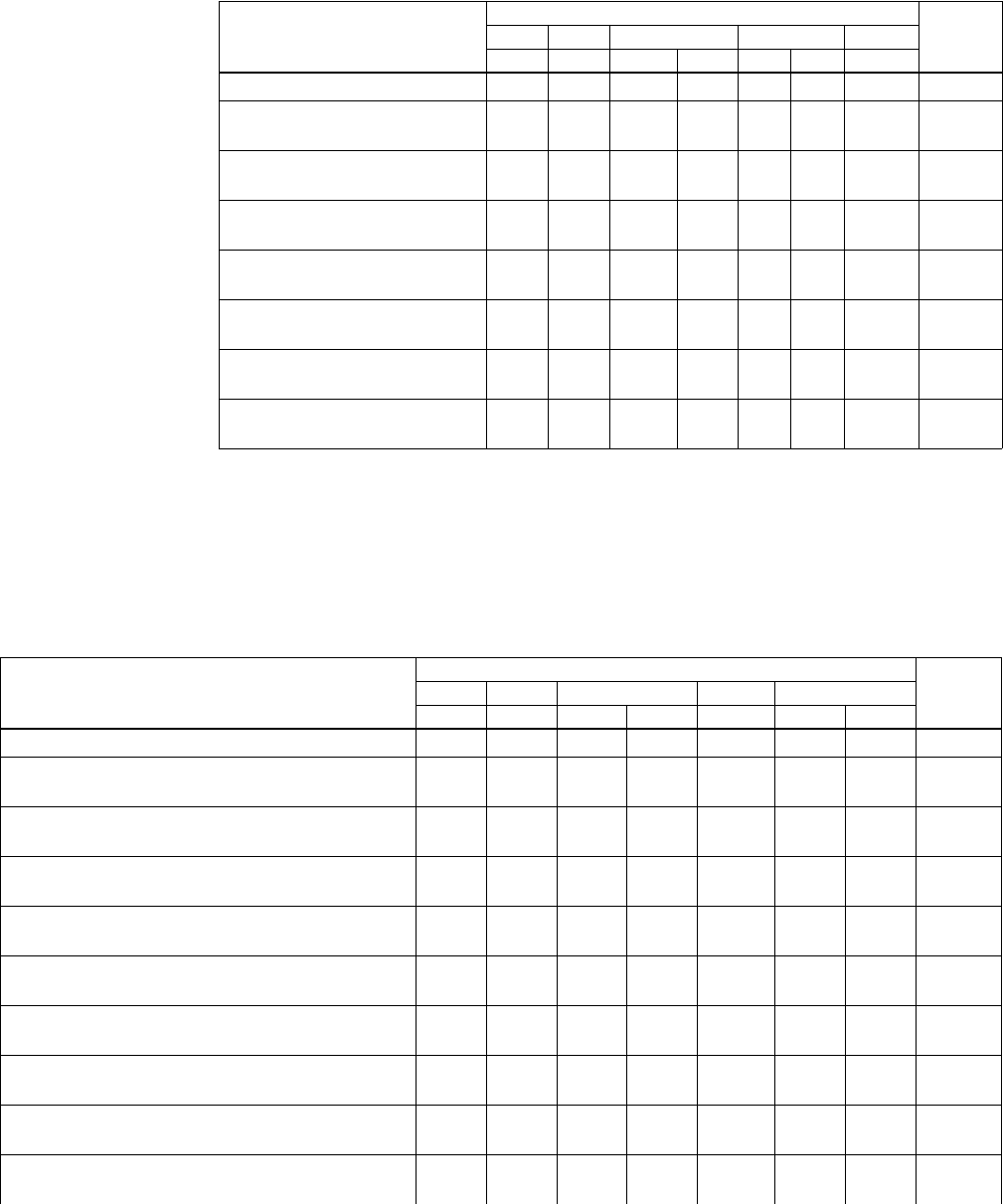
Video Test Generator User Guide 319
2. Using the table below, determine the proper “L” field code for bits 3-9.
3. Use the following table to determine the proper “K” field code for bits 10-16.
Letterbox/Pillar Mode
“L” Field Code
Symbol
Undo Bars BarContents Position Shrink
Bit 9 Bit 8 Bit 71
1. Bits 6 and 7 are used to sequence redundant AFD codes.
In the case of pixel repetition (NPPP not equal to 0), the color of the (extended) bars
on the left and right sides of the image are filled in accordance with the settings of bits
6 and 7—even when the letterbox/pillar fitting method is disabled (bit 3 = 0).
Bit 61Bit 5 Bit 4 Bit 3
Disabled 0 0 0 0 0 0 0
Centered shrink w/black bars
top & bottom 0100001Lcbb
Centered shrink w/gray bars
top & bottom 0101001Lcgb
Centered shrink w/white bars
top & bottom 0 1 1 0 0 0 1 Lcwb
Centered protected shrink
w/shot surround 0 0 0 0 0 0 1 Lcsp
Top shrink w/single black bar at
bottom 01 0001 1 Ltbb
Top shrink w/single gray bar at
bottom 01 0101 1 Ltgb
Top shrink w/white bar at bot-
tom 01 1001 1 Ltwb
(Keep) Safe Area Mode
“K” Field Code
Symbol
Undo Bars BarContents Source Save Area
Bit 16 Bit 15 Bit 14 Bit 13 Bit 12 Bit 11 Bit 10
None (w/safe area markers) 0 0 0 0 0 0 0
Shrink coded frame to action area with opaque
black bar surround 0100 0 01Kabb
Shrink coded frame to action area with opaque
gray bar surround 0101 0 01Kagb
Shrink coded frame to action area with opaque
white bar surround 0110 0 01Kawb
Coded frame has shot-protected action area with-
out graticules or bars 0000 0 01Kasp
Coded frame has shot-protected action area with
action graticules without bars 0001 0 01Kaspa
Coded frame has shot-protected action area with
title graticules without bars 0010 0 01Kaspt
Coded frame has shot-protected action area with
action and title graticules without bars 0011 0 01Kaspb
Shrink coded frame to title area with opaque black
bar surround 0100 0 10Ktbb
Shrink coded frame to title area with opaque gray
bar surround 0101 0 10Ktgb

320 Appendix A Command Reference
Shrink coded frame to title area with opaque white
bar surround 0110 0 10Ktwb
Coded frame has shot-protected title area without
graticules or bars 0000 0 10Ktsp
Coded frame has shot-protected title area with
action graticules without bars 0001 0 10Ktspa
Coded frame has shot-protected title area with title
graticules without bars 0010 0 10Ktspt
Coded frame has shot-protected title area with
action and title graticules without bars 0011 0 10Ktspb
Coded frame has shot-protected custom area with-
out graticules or border 0000 0 11Kcsp
Coded frame has shot-protected custom area with
action graticules without border 0001 0 11Kcspa
Coded frame has shot-protected custom area with
title graticules without border 0010 0 11Kcspt
(Keep) Safe Area Mode
“K” Field Code
Symbol
Undo Bars BarContents Source Save Area
Bit 16 Bit 15 Bit 14 Bit 13 Bit 12 Bit 11 Bit 10

Video Test Generator User Guide 321
The following table provides mapping codes used by AFD (see XAFD).
Related commands CXAR, EXAR, SXCX, SXEX
Example
EXCX 8 // Use centered protected shrink w/shot surround mode
FMTU
Method Binary Field Code Decimal Code Symbol
Natural aspect ratio 00000000000000000 0 N0
00000000000010000 16 N1
00000000000100000 32 N2
Squeeze (anamorphise) 00000000000000001 1 S
Centered protected shrink with shot surround 00000000000001000 8 Lcsp
Centered shrink with black bars top and bottom 00000000100001000 264 Lcbb
Top shrink with single black bar at bottom 00000000100011000 280 Ltbb
Shrink coded frame to title area w/ opaque black bar surround 01000100000000000 34816 Ktbb
322 Appendix A Command Reference
FDTA Font DaTA
Class
Description Writes font data. It takes as arguments table (the table from which to read), index (the
index of the item within the table), and value (the data to be written to the table).
The FDTA? query reads font data. It takes as arguments table (the table from which to
read) and index (the index of the item within the table). It returns value (the data to be
written to the table).
The table argument must be one of the following:
• 0 = The header, treated as an uint16[ ].
• 1 = The character pattern, an uint32[ ].
• 2 = The location table, an uint16[ ].
• 3 = The offset/width table, an uint16[ ].
• 4 = The image width table, an uint8[ ].
Note: The index range for table #0 must be: 0 = index 13. The index range for the other
tables depends on the font size.
Command syntax FDTA table index value
table
positive integer number
index
positive integer number
value
positive integer number
Query syntax FDTA? table index
table
positive integer number
index
positive integer number
Related commands FDTA
Video Test Generator User Guide 323
FLSH FLaSH new firmware via GPIB
Class System Level
Description Changes the firmware in the generator’s flash EPROM via the GPIB port. This is
accomplished by sending an IEEE 488.2 standard arbitrary block program data to the
generator. The generator temporarily places the block in picture memory and, if received
intact, eventually transfers the binary image to flash memory by internally executing the
VTOF function. Note that one does not have to send VTOF after a FLSH transfer.
FLSH initiates the data transfer. An arbitrary_block_program_data argument containing
either 512K or 2M bytes of binary data should follow this command per standard
IEEE-448.2 section 7.7.6 GPIB data transfer methods.
Command syntax FLSH arbitrary_block_program_data
arbitrary_block_program_data
IEEE-488.2 arbitrary block program data per standard IEEE-448.2 section 7.7.6 GPIB
data transfer method. The maximum number of bytes sent depends on the generator:
801requires a maximum of 524288 bytes, while 802 requires a maximum of 2097152
bytes.
Related commands YMDI, VTOF
Example
FLSH #6524288 …EPROM data bytes…
324 Appendix A Command Reference
FMTA ForMaT save As
Class Format memory management
Description Saves the current contents of the format edit buffer using the given name
Command syntax FMTA name
name
a valid MS-DOS filename (8 characters minus any extension)
Example
FMTA MY_FMT // Save with the name "MY_FMT"
Video Test Generator User Guide 325
FMTB ForMaT editing Begin
Class Format editor control
Description Marks the beginning of a format editing session.
Command syntax FMTB
Other required
commands Use either an FMTL command to load an existing image or an FMTN command to create
a new format. Use FMTE when ending the editing session.
Example
FMTN // Initialize format edit buffer
FMTB // Start format editing session
// One or more format editing commands ...
FMTE // End format editing session
326 Appendix A Command Reference
FMTE ForMaT editing End
Class Format editor control
Description Marks the end of a format editing session.
Command syntax FMTE
Other required
commands Use FMTB when starting the editing session. Use FMTA or FMTS to save changes.
Example
FMTB // Start format editing session
// One or more format editing commands ...
FMTA My_fmt1 // Save edited format as My_fmt1
FMTE // End format editing session
Video Test Generator User Guide 327
FMTG? ForMaT in buffer Good
Class Format memory management
Description Tests the format in the format buffer for errors. If no errors are found, FMTG? returns zero.
Otherwise, if one or more errors exist, the number of the first error encountered is
returned. To test formats residing in format memory, use the FMTT? query.
Query syntax FMTG?
Query response Returns 0 if no errors are found; otherwise, returns the number of the first error
encountered.
Example
FMTG? // Return format error status
328 Appendix A Command Reference
FMTJ ForMaT Justify
Class Format memory management
Description Corrects some types of timing errors for the current data in the format buffer. The following
errors are corrected:
• Pixel Rate errors 2071 and 2072
• Video Memory Size error 2550
• Horizontal Blanking errors 2140, 2141, 2150 and 2155
• Horizontal Total errors 2090 and 2091
• Horizontal Sync Pulse Width errors 2181 and 2201
The justification routine tries to keep the format close to your original specifications.
However, the format should be reviewed after it is justified to make sure it still meets your
timing requirements.
Command syntax FMTJ
Other required
commands The FMTU command instructs the generator to use the new settings. The ALLU command
updates hardware to the new settings and redraws the test image. The FMTG? query can
be used to see if any errors remain.
Example
FMTJ
FMTU // Update hardware to current buffer contents
Video Test Generator User Guide 329
FMTK ForMaT Kill from memory by name
Class Format memory management
Description Erases the named format from memory. The FMTK? query checks to see if the named
format can be erased. The RAM location number is returned if it can be erased.
Otherwise, a zero is returned.
Command syntax FMTK name
name
a valid MS-DOS filename (8 characters minus any extension)
Query syntax FMTK? name
name
valid MS-DOS filename (8 characters minus any extension)
Query response 0 or location
Example
FMTK my_fmt1 // Erase format called my_fmt1
330 Appendix A Command Reference
FMTL ForMaT Load from memory by name
Class Format memory management
Description Assigns a format to the current step of a sequence while between a set of SEQB and
SEQE commands. The FMTL command is context sensitive. The FMTL? query returns
the name of the format currently assigned to the step.
Outside of the sequence editor, the FMTL command reads the format having a name
equal to name from format memory (or EPROM) into the format. FMTL does not
reconfigure the signal generating hardware. This feature allows you to work on the
contents of any format memory location, while continuing to output a signal based on a
previously used format (see FMTU command). The FMTL? query returns the location
location in which a format having a name equal to name is found. If multiple formats exist
having name name, then the lowest numbered location containing a format with a
matching name name is returned. The format memory (RAM) is always searched first. If a
format with name name cannot be found anywhere in the format memory, then the
industry-standard formats located in EPROM (negative locations) are searched next.
The FMTL? query returns zero if a format with a name equal to name cannot be found in
either format space.
Command syntax FMTL name
name
a valid MS-DOS filename (8 characters minus any extension)
Query syntax FMTL? name
Query response location (returns 0 if not found)
Other required
commands The ALLU command updates the hardware to the new settings and redraws the test
image.
Example
FMTL VGA_m3 // Load format called VGA_m3
ALLU // Update hardware and redraw image
Video Test Generator User Guide 331
FMTN ForMaT New
Class Format memory management
Description Initializes the format editing buffer. Sending this one command is equivalent to sending all
of the following commands:
This should be the first command sent to the generator when creating a new format. The
command only resets to a known state. The command does not create a usable format.
The FMTN? query returns the current name of the format in the buffer.
Command syntax FMTN name
name
a valid MS-DOS filename (8 characters minus any extension)
Query syntax FMTN?
ASBG 0 GAMA 2.2
ASCT 1 GAMC 0
ASGG 1 HRAT 0
ASSG 0, 1, 0 HRES 0
ASSS 0.286 HSIZ 280
AVPG 0 HSPD 0
AVPS 0.0 HSPG 1
AVSB 0.0 HSPP 0
AVSS 0.714 HSPW 0
AVST 0 HTOT 0
XVSG 1, 1, 1 SCAN 1
CSPG 1 SSST 1
CSPP 0 USIZ 2
DCBM 0 VRES 0
DSEX 0 VSIZ 210
DSST 1 VSPD 0
DVSP 0 VSPG 1
DVST 0 VSPP 0
EQUA 0 VSPW 0
EQUB 0 VTOT 0
332 Appendix A Command Reference
Query response name
Example
FMTN // Initialize format buffer
or
FMTN Narf // Initialize format buffer and name the format "Narf"
Video Test Generator User Guide 333
FMTP ForMaT Path
Class Format memory management
Description Sets the current format path name to a given directory. The query will return the current
format path name.
Command syntax FMTP name
name
a valid MS-DOS filename (8 characters minus any extension)
Query syntax FMTP?
Query response name
Example
DIRQ? // List directory objects
FMT
IMG
VGA_FMTS
SEQ
FMTP VGA_FMTS // Load a custom format knob list
FMTP FMT // Load the default format knob list
334 Appendix A Command Reference
FMTQ? ForMaT Query pointer
Class Format memory management
Description Returns number format names from the list of all the formats stored in format memory
beginning at index. The formats are kept in alphanumeric order. The generator maintains
internal variables for the current index and number values. The value of index is
automatically incremented by number after the query is executed. Sending the query with
just an index parameter returns the same number of names as the last time, starting at the
given index. Sending the query with no parameters, returns the next set of names.
Query syntax FMTQ? [index [number]]
index
positive integer number
number
positive integer number
Query response List of specified format names
Example
FMTQ? 1 9999 // List all formats in memory
or
FMTQ? 1 10 // List the first ten formats in memory
FMTQ? 21 // List the 21st through the 30th FMTes in memory
FMTQ? // List the 31st through the 40th FMTes in memory
Video Test Generator User Guide 335
FMTR ForMaT Read from memory location (by number)
Class Format memory management
Description Reads format from the format memory location into the format buffer. The FMTR
command does not reconfigure the signal generating hardware. The FMTR? query returns
the name of the format stored in location location. FMTR? returns the string EMPTY if the
format memory location location is empty.
Command syntax FMTR location
location
1 through 300 (RAM)
-1 through -24 (EPROM)
Query syntax FMTR? location
Query response name
Other required
commands The ALLU command updates the hardware to the new settings and redraws the test
image.
Example
FMTR -5 // Load format from ROM location 5
ALLU // Update hardware and redraw image
336 Appendix A Command Reference
FMTS ForMaT Save
Class Format memory management
Description Saves the current format edit buffer contents into format memory using the current name
of the format in the edit buffer.
Command syntax FMTS
Example
FMTL DMT0660 // Loads a format for editing
FMTB // Begins and editing session
HRES 654 // Sets the horizontal resolution to 654 pixels
.
. // other format parameters
.
HTOT 720 // Sets the horizontal total to 720 pixels
FMTE // Ends the format editing session
FMTS // Saves format
Video Test Generator User Guide 337
FMTU ForMaT Use
Class Format memory management
Description Checks the current contents of the format buffer for errors; if no errors are found, it
reconfigures the signal generating hardware in accordance with the contents. It does not
redraw the previously displayed test image. In some cases this may distort the old image.
The FMTU? query returns either a format memory location location or zero. If the signal
format currently being output by the signal generating hardware matches that originally
loaded (using the FMTL command) or read (using the FMTR command) from a format
memory location, then the matching format memory location location is returned.
Otherwise, if the format contents have been used to update the signal generating
hardware since either an FMTR or FMTL command has been issued, then FMTU? query
returns zero.
Command syntax FMTU
Query syntax FMTU?
Query response location or 0
338 Appendix A Command Reference
FMTZ ForMat Zap
Class Format memory management
Description Clears format storage memory starting at first and ending at last. The cleared locations are
then tagged as being empty. If no last parameter is given, only the first location is cleared.
The FMTZ? query is used to determine if a location contains a format or is empty.
Command syntax FMTZ first last
Query syntax FMTZ? location
Video Test Generator User Guide 339
FORM draw FORMat data block
Class Custom image primitive
Description Displays basic information about the format driving the display. The first line shows the
number of horizontal active pixels and vertical active lines. The last number on the line is
the number of fields per frame (1 for non-interlaced and 2 for interlaced). The second and
third lines show the horizontal and vertical rates, respectively. Text is on a black
rectangular background with a single pixel border.
FORM uses three (3) parameters. The first is the color of the text and border. The next two
are the X and Y coordinates for the top left corner of the block of text.
Command syntax FORM color x y
color
available colors
x
positive integer number
y
positive integer number
Other required
commands The FMTU command instructs the generator to use the new setting. The ALLU command
updates hardware to the new setting and redraws the test image.
Example
FORM blue 30 200 // Display format information
// in blue beginning at X=30, Y=200
ALLU // Update hardware to current buffer contents
Video Test Generator User Guide 341
FRGB Foreground Red, Green and Blue levels
Class System parameter settings
Description Temporarily sets the portions of an image drawn with a color selection of foreground to the
given red, green and blue values. All three colors can be set to the same level using a
single parameter. The color selection for one or more primitives in a custom image must
be set to foreground in order to see the affect of this command on a custom image. The
setting is not global and is not saved. The FRGB? query returns the current red, green and
blue settings of FRGB.
Command syntax FRGB red_level green_level blue_level
or
FRGB common_gray_level
level
min = 0 (full off)
max = 255 (full on)
Query syntax FRGB?
Query response red_level green_level blue_level
Example
FRGB 255 128 0 // Set foreground color to orange
or
FRGB 128 // Set foreground color to a mid-gray level
342 Appendix A Command Reference
FSPD Frame Sync Pulse Delay
Class Format parameter setting - Synchronization
Description Sets the delay of the frame sync pulse relative to the last line of active video in the current
format. The FSPD? query returns the current FSPD setting.
Command syntax FSPD delay
delay
min = 0 lines
max = (VTOT/SCAN) line
Query syntax FSPD?
Query response delay
Other required
commands To get a pulse, frame sync must first be enabled with the FSPG command. The FMTU
command instructs the generator to use the new settings. The ALLU command updates
the hardware to the new settings and redraws the test image.
Example
FSPG 1 // Enable Frame Sync
FSPP 1 // Set for positive going pulse
FSPW 20 // Make the pulse 20 pixels wide
FSPG 300 // Pulse to occur 300 lines after
// the last line of active video
FMTU // Update hardware to new settings
Video Test Generator User Guide 343
FSPG Frame Sync Pulse Gate
Class Format parameter setting - Synchronization
Description Enables and disables the digital horizontal sync output. The FSPG? query returns the
current FSPG mode.
Command syntax FSPG mode
mode
0 = OFF
1 = ON
Query syntax FSPG?
Query response 0 or 1
Other required
commands The FMTU command instructs the generator to use the new settings. The ALLU command
updates the hardware to the new settings and redraws the test image.
Example
FSPG 1 // Enable Frame Sync
FMTU // Update hardware to new settings
344 Appendix A Command Reference
FSPP Frame Sync Pulse Polarity
Class Format parameter setting - Synchronization
Description Establishes the logic sense of the digital frame sync output. Setting polarity to one (1)
causes the leading edge of frame sync to be a low-to-high transition. Setting polarity to
zero (0) causes the leading edge of frame sync to be a high-to-low transition. The FSPP?
query returns the current polarity of FSPP.
Command syntax FSPP polarity
polarity
0 = active-low (negative going pulse)
1 = active-high (positive going pulse)
Query syntax FSPP?
Query response 0 or 1
Other required
commands To get a pulse, frame sync must first be enabled with the FSPG command. The FMTU
command instructs the generator to use the new settings. The ALLU command updates
the hardware to the new settings and redraws the test image.
Example
FSPG 1 // Enable Frame Sync
FSPP 1 // Set for positive going pulse
FSPW 20 // Make the pulse 20 pixels wide
FSPG 300 // Pulse to occur 300 lines after
// the last line of active video
FMTU // Update hardware to new settings
Video Test Generator User Guide 345
FSPW Frame Sync Pulse Width
Class Format parameter setting - Synchronization
Description Establishes the width of the frame sync pulse. The FSPW? query returns the current
setting of FSPW.
Command syntax FSPW pixels
pixels
min = 1
max = HTOT - 1
Query syntax FSPW?
Query response pixels
Other required
commands The FMTU command instructs the generator to use the new settings. The ALLU command
updates the hardware to the new settings and redraws the test image.
Example
FSPG 1 // Enable Frame Sync
FSPP 1 // Set for positive going pulse
FSPW 20 // Make the pulse 20 pixels wide
FSPG 300 // Pulse to occur 300 lines after the last line of active video
FMTU // Update hardware to new settings
346 Appendix A Command Reference
GAMA GAMmA correction factor
Class Format parameter setting - Digital video signal
Description Establishes the current video gamma correction factor. The GAMA? query returns the
current setting of the gamma correction factor.
Command syntax GAMA factor
factor
min = 0.1 (floating point accepted)
max = 10.0 (floating point accepted)
For HDMI video signals GAMA is always 2.222
Query syntax GAMA?
Query response factor
Other required
commands Gamma correction must be enabled with the GAMC command in order to use the gamma
correction factor. The FMTU command instructs the generator to use the new setting. The
ALLU command updates hardware to the new setting and redraws the test image.
Example
GAMC 1 // Enable gamma correction in buffer
GAMA 2.2 // Set correction factor in buffer
FMTU // Update hardware to current buffer contents
Video Test Generator User Guide 347
GAMC GAMma Correction mode
Class Format parameter setting - Digital video signal
Description Enables or disables application of the video gamma correction factor. The GAMC? query
can be used to determine if the gamma correction factor is currently being applied.
Command syntax GAMC mode
mode
0 = disable (don't correct)
1 = enable (correct)
Query syntax GAMC?
Query response 0 or 1
Other required
commands The value used for gamma correction is set with the GAMA command. The FMTU
command instructs the generator to use the new setting. The ALLU command updates
hardware to the new setting and redraws the test image.
Example
GAMC 1 // Enable gamma correction in buffer
GAMA 2.2 // Set correction factor in buffer
FMTU // Update hardware to current buffer contents
348 Appendix A Command Reference
GCET?
Get Component Error Tallies
Class DVI signal analyzer
Description Reads the number of errors in the red, green, and blue components along with the total
number of bad pixels.
Query syntax GCET?
Query response R, G, B, and bad pixels
Example
PNAU //Pseudo-random noise generated
CR //Stop pseudo-random noise
GCET?
0,21,0,21 //Returns 21 Green pixel errors and a total of 21 bad pixels
Related commands PNAU
Video Test Generator User Guide 349
GETA?
GET data from Absolute memory location
Class Direct processor control
Description Returns the value of the data stored at the memory address specified. Up to 32 bits can be
read with this query (see SIZE command). The returned value value is formatted
according to the current setting of BASE (see the BASE command).
Note: This command is used only with custom applications and command files created by
Quantum Data.
Query syntax GETA? address
address
0 to 4,294,967,295 (BASE = 10)
-2,147,483,648 to 2,147,483,647 (BASE = -10)
0 to FFFFFFFF (BASE = 16)
-80000000 to 7FFFFFFF (BASE = -16)
Query response value
Other required
commands GETAand GETA? expect and return parameters formatted according to the current radix
set by the BASE command.
350 Appendix A Command Reference
GETR?
GET data from Relative memory location
Class Direct processor control
Description Returns the value of the data stored at the memory location currently pointed to by the
address register (see ADDR command). Up to 32 bits can be read with this query (see
SIZE command). The returned value value is formatted according to the current setting of
BASE (see the BASE command). The address register is automatically incremented by
SIZE bits after the current location has been read.
Note: This command is used only with custom applications and command files created by
Quantum Data.
Query syntax GETR?
Query response value
Other required
commands GETR and GETR? expect and return parameters formatted according to the current radix
set by the BASE command.
Video Test Generator User Guide 351
GFED?
Get First Error Data
Class DVI signal analyzer
Description Returns information about the first error encountered.
Query syntax GFED?
Query response expected value followed by the errant value (in hex)
Example
PNAU //Pseudo-random noise generated
CR //Stop pseudo-random noise
GFED? //Returns expected (40018C) and errant (FFFFFF) value of first
errored pixel
40018C,FFFFFF
Related commands PNAU
352 Appendix A Command Reference
GLUT
Get LUT from hardware
Class Lookup Table Memory Management
Description Copies the current values from the hardware lookup table to the lookup table edit buffer.
Command syntax GLUT
Video Test Generator User Guide 353
GMAP
Get pixel MAP from frame buffer
Class Bitmap image control
Description The GMAP command
Command syntax GMAP width height x y name
width
height
x
y
name
Other required
commands The contents of the temporary buffer can not be edited directly. The MAPL command must
be used to copy the temporary buffer contents to the edit buffer.
Example
GMAP 3 3 5 5 thismap // get a new map named thismap from frame buffer
MAPL mymap // load bitmap mymap into edit buffer
MAPB // begin map editing context
354 Appendix A Command Reference
GNPT?
Get Number of Pixel Tested
Class Signal analyzer - Pixel data
Description Returns the number of pixels being measured in billions after a pseudo noise
measurement has finished execution (that is, completed the PNAU command).
Query syntax GNPT?
Query response number of pixels
Example
PNAU //Pseudo-random noise generated
CR //Stop pseudo-random noise
GNPT? //Returns 4.255 billion pixels
4.255
Related commands PNAU
Video Test Generator User Guide 355
GPEL?
Get PixEL color components
Class Signal analyzer - Pixel data
Description Takes the (x, y) coordinates address of a pixel and returns the red, green, and blue color
components of the pixel at that address.
Query syntax GPEL? x y
Query response R, G, B
Possible errors Should this info be integrated into the Query response area, instead of creating a new
label?The GPEL? query may respond back with one of the following errors in case of a
parameter is not set correctly (or in case the setup is not correct).
Example
PDSX 128 //sets patch starting at x-pixel 128
PDSY 256 //sets patch starting at y-pixel 256
PDSH 64 //sets patch height at 64 pixels
PDSW 96 //sets patch width at 90 pixels
PDAU //captures patch of image
GPEL? 128 256 //read RGB color components at pixel address 128,256
0,255,0
Related commands PDAU
PNSeedExceedsLimit 2800
PNLengthExceedsLimit 2801
PNNotSupported 2802
NoInputSupported 2803
XcoordOutOfRange 2804
YcoordOutOfRange 2805
356 Appendix A Command Reference
GPER?
Get Pixel Error Rate
Class Signal analyzer - Pixel data
Description Returns the pixel error rate in errors per billion after a pseudo noise measurement has
finished execution (that is, completed the PNAU command).
Query syntax GPER?
Query response pixel error rate
Example
PNAU //Pseudo-random noise generated
CR //Stop pseudo-random noise
GPER? //Returns 0.88 billion pixel errors
0.88
Related commands PNAU
Video Test Generator User Guide 357
GPIB GPIB address
Class GPIB port control
Description Sets the address of the generator on the GPIB port. The address change takes affect as
soon as the command is issued. The new address setting will be maintained until 1) the
address is changed another GPIB command, 2) the unit is re-initialized with an INIT
command or 3) the unit is re-initialized because the power-up self-test found corrupted
data in battery backed system memory. In cases 2 and 3, the GPIB address will revert to
the address set on the GPIB address switches, if the unit has them. The address reverts to
15 if the unit does not have GPIB address switches. The GPIB? query returns the current
GPIB address of the unit.
Command syntax GPIB address
address
integer, 0-30
Query syntax GPIB?
Query response address
Example
GPIB 5 // Set GPIB address to 5
358 Appendix A Command Reference
GRID draw a centered GRID
Class Custom image primitive
Description Draws a crosshatch of a given color and forms a given number of boxes in each direction.
All lines are 1 pixel thick. All of the lines in a given direction are equally spaced. Any
remaining pixels are distributed as equally as possible around the perimeter of the grid.
This may cause the first and last lines in each direction not to be at the very edges of
video.
Command syntax GRID color horizontal_boxes vertical_boxes
color
available colors
horizontal_boxes
number of horizontal boxes (half of number of pixels)
vertical_boxes
number of vertical boxes (half of number of lines)
Other required
commands The FMTU command instructs the generator to use the new settings. The ALLU command
updates the hardware to the new settings and redraws the test image.
Example
GRID gray75 14 10 // Draw a gray75 grid with 14 horizontal
// and 10 vertical boxes
ALLU // Update hardware to current buffer contents
Video Test Generator User Guide 359
GRIH draw a GRIll pattern of Horizontal lines
Class Custom image primitive
Description Draws equally spaced horizontal lines that form a grill over the entire active video area.
The primitive uses three parameters. The first is the color of the lines, the second is the
thickness of the lines, and the third is the thickness of the space between the lines.
Command syntax GRIH color line_width space_width
color
available colors
line_width
number of pixels in line
space_width
number of pixels in space
Other required
commands The FMTU command instructs the generator to use the new settings. The ALLU command
updates the hardware to the new settings and redraws the test image.
Example
GRIH green 4 6 // Draw green grid with 4-pixel lines and 6-pixel spaces
ALLU // Update hardware to current buffer contents
360 Appendix A Command Reference
GRIV draw a GRIll pattern of Vertical lines
Class Custom image primitive
Description Draws equally spaced vertical lines that form a grill over the entire active video area. The
gaps are not touched and will show any previously drawn primitives. The primitive uses
three parameters. The first is the color of the lines, the second is the thickness of the lines,
and the third is the thickness of the space between the lines.
Command syntax GRIV color line_width space_width
color
available colors
line_width
number of pixels in line
space_width
number of pixels in space
Other required
commands The FMTU command instructs the generator to use the new settings. The ALLU command
updates the hardware to the new settings and redraws the test image.
Example
GRIV cyan 16 16 // Draw cyan grill with 16-pixel lines
// and 16-pixel spaces
ALLU // Update hardware to current buffer contents
Video Test Generator User Guide 361
GRNG GRNe Gate
Class Video Gate
Description Toggles the green video signal gate.
Command syntax GRNG mode
mode
0 = disable
1 = enable
Query syntax GRNG?
Query response 0 or 1
Other required
commands ALLU to invoke the command.
Related commands BLUG, REDG
Example
GRNG 0; ALLU // disable green video component
362 Appendix A Command Reference
GTLS Go To Local State
Class System Control
Description Enables the use of the front panel keys and knobs (local operation) on the unit that may
have been previously disabled with the LLOS command. The GTLS? query returns the
current state of local operation.
Command syntax GTLS
Query syntax GTLS?
Query response 0 or 1
0 = local state disabled (local lockout enabled)
1 = local state enabled (local lockout disabled)
Video Test Generator User Guide 363
HATI draw a centered crossHATch from the Inside out
Class Custom image primitive
Description Draws a crosshatch from the inside-out of a given color and forms a given number of
boxes in each direction. The primitive has center lines that divide the active video exactly
in half in each direction. The vertical center line is 2 pixels thick if the format has an even
number of active pixels. The horizontal center line is 2 pixels thick if the format has an
even number of active lines. All other lines are 1 pixel thick. If you enter an odd number of
boxes, a half box is placed at each end of the crosshatch. All lines in a given direction are
spaced equally. Any remaining pixels are distributed as equally as possible around the
perimeter of the grid. This may cause the first and last lines in each direction not to be at
the very edges of video. In turn, this may cause any half boxes to be slightly larger.
Command syntax HATI color horizontal_boxes vertical_boxes
color
available colors
horizontal_boxes
number of horizontal boxes (half of number of pixels)
vertical_boxes
number of vertical boxes (half of number of lines)
Other required
commands The FMTU command instructs the generator to use the new settings. The ALLU command
updates the hardware to the new settings and redraws the test image.
Example
HATI green 15 9 // Draw a green grid with 15 horizontal
// and 9 vertical boxes
ALLU // Update hardware to current buffer contents
364 Appendix A Command Reference
HATO draw a centered crossHATch from the Outside in
Class Custom image primitive
Description Draws a crosshatch from the outside-in of a given color and forms a given number of
boxes in each direction. All lines are 1 pixel thick. The first and last lines in each direction
are at the very edges of active video. All the lines in a given direction are spaced equally.
Any remaining pixels are added to the boxes along the horizontal and vertical centers of
the image.
Command syntax HATO color horizontal_boxes vertical_boxes
color
available colors
horizontal_boxes
number of horizontal boxes (half of number of pixels)
vertical_boxes
number of vertical boxes (half of number of lines)
Other required
commands The FMTU command instructs the generator to use the new settings. The ALLU command
updates the hardware to the new settings and redraws the test image.
Example
HATO yellow 15 9 // Draw a yellow grid with 15 horizontal
// and 9 vertical boxes
ALLU // Update hardware to current buffer contents
Video Test Generator User Guide 365
HDCP? HDCP
Class HDCP
Description: The HDCP query is used to control HDCP tests.
Query syntax HDCP? [A1 | A2] [B1 | B2] [frames]
A1
runs the test with public keys A1
A2
runs the test with public keys A2
B1
runs the test with public keys B1
B2
runs the test with public keys B2
frames
The number of frames to be tested. The default is 512.
Example
HDCP? 2000 // run test with production keys for 2000 frames
HDCP? a2 b1 2000 // run test with public keys a2, b1 for 2000 frames
For additional examples, see “Using command-line interface to control HDCP” on page
190.

366 Appendix A Command Reference
HDMI
High-Definition Multimedia Interface protocol
Class Digital video signal control
Description Sets the current digital protocol. Restarting the generator does not change this setting.
The HDMI? query returns the current mode.
Command syntax HDMI mode
mode
0 to disable HDMI (use alternative protocol such as DVI 1.0)
1 to enable HDMI (default)
This command affects the DVPT parameter as shown below:
Query syntax HDMI?
Query response 0 or 1
Example
HDMI 0
ALLU
Interface hardware used HDMI setting DVPT setting
DVI only 0 0
12
HDMI 0 1
10
Video Test Generator User Guide 367
HRAT Horizontal RATe
Class Format parameter setting - Video resolution
Description Sets the line frequency. Pixel rate is equal to HTOT multiplied by HRAT. Frame rate is
equal to HRAT divided by VTOT. Field rate is equal to SCAN multiplied by the frame rate.
The HRAT? query returns the current horizontal frequency setting.
Command syntax HRAT frequency
frequency
typical min = 1000 Hz (floating point accepted)
typical max = 130000 Hz (floating point accepted)
Query syntax HRAT?
Query response frequency in Hz (floating point returned)
Other required
commands The FMTU command instructs the generator to use the new settings. The ALLU command
updates the hardware to the new settings and redraws the test image.
Example
HRAT 32768 // Set 32.768 kHz rate in buffer
FMTU // Update hardware to current buffer contents
or
HRAT 32.768E3 // Set a 32.768 kHz rate
FMTU // Update hardware to current buffer contents
368 Appendix A Command Reference
HRES Horizontal RESolution
Class Format parameter setting - Video resolution
Description Establishes the number of active pixels per line. The HRES? query returns the current
setting of HRES.
Command syntax HRES pixels
pixels
min = 16
max depends on VRES and model of generator
Query syntax HRES?
Query response pixels
Other required
commands The ALLU command updates hardware to the new setting and redraws the test image.
Example
HRES 480 // Set 480 active pixels line in buffer
ALLU // Configure hardware and redraw image
Video Test Generator User Guide 369
HSIZ Horizontal SIZe
Class Format parameter setting - Video resolution
Description Establishes the horizontal physical size of the image on the display. Units expected (or
returned) vary according to the last mode set with USIZ command. The HSIZ command is
context sensitive and must appear between begin and end commands FMTB and FMTE.
The HSIZ? query returns the current setting of HSIZ.
Note: Make sure that the USIZ parameter is properly set before using the HSIZ command.
Changing the USIZ setting after entering HSIZ will convert the size to match the new unit
of measure.
Command syntax HSIZ physical_size
physical_size
positive value (floating point accepted)
Query syntax HSIZ?
Query response Returns physical size (floating point returned)
Other required
commands The units of measure must be properly set by USIZ before entering HSIZ. The ALLU
command updates hardware to the new setting and redraws the test image, taking the
new size into account.
Example
FMTB // Begin editing session One or more format editing commands
// ...
USIZ 1 // Select inches as unit of measure in buffer
HSIZ 10.4 // Set width to 10.4 in buffer
VSIZ 7.8 // Set height to 7.8 in buffer
ALLU // Test the new settings
// more format editing commands
// ...
FMTE // End of editing session
370 Appendix A Command Reference
HSPD Horizontal Sync Pulse Delay
Class Format parameter setting - Synchronization
Description Establishes the delay between the leading edge of blanking and the leading edge of the
horizontal sync pulse. The HSPD? query returns the current setting of HSPD.
Command syntax HSPD pixels
pixels
min = 1
max = HTOT - HRES - HSPW
Query syntax HSPD?
Query response pixels
Other required
commands The FMTU command instructs the generator to use the new settings. The ALLU command
updates the hardware to the new settings and redraws the test image.
Example
HSPD 16 // Set 16 pixel pulse delay in buffer
FMTU // Update hardware to current buffer contents
Video Test Generator User Guide 371
HSPG Horizontal Sync Pulse Gate
Class Format parameter setting - Synchronization
Description Enables and disables the digital horizontal sync output. The HSPG? query returns the
current HSPG mode.
Command syntax HSPG mode
mode
0 = OFF
1 = ON
Query syntax HSPG?
Query response 0 or 1
Other required
commands To use digital horizontal sync, digital separate H and V sync must be selected with the
SSST command. The FMTU command instructs the generator to use the new settings.
The ALLU command updates the hardware to the new settings and redraws the test
image.
Example
HSPG 1 // Enable H sync output in buffer
FMTU // Update hardware to current buffer contents
372 Appendix A Command Reference
HSPP Horizontal Sync Pulse Polarity
Class Format parameter setting - Synchronization
Description Establishes the logic sense of the digital horizontal sync outputs. Setting polarity to 1
causes the leading edge of horizontal sync to be a low-to-high transition. Setting polarity to
0 causes the leading edge of horizontal sync to be a high-to-low transition. The HSPP?
query returns the current polarity of HSPP.
Command syntax HSPP polarity
polarity
0 = active-low (negative going pulse)
1 = active-high (positive going pulse)
Query syntax HSPP?
Query response 0 or 1
Other required
commands To use digital horizontal sync, it must be gated on with the HSPG command and digital
separate H and V sync must be selected with the SSST command. The FMTU command
instructs the generator to use the new settings. The ALLU command updates the
hardware to the new settings and redraws the test image.
Example
HSPP 0 // Set active low H sync in buffer
HSPG 1 // Enable H sync output in buffer
SSST 1 // Select H&V sync type in buffer
FMTU // Update hardware to current buffer contents
Video Test Generator User Guide 373
HSPW Horizontal Sync Pulse Width
Class Format parameter setting - Synchronization
Description Establishes the width of the horizontal sync pulse. The HSPW? query returns the current
setting of HSPW.
Command syntax HSPW pixels
pixels
min = 1
max = HTOT - HRES - HSPD
Query syntax HSPW?
Query response pixels
Other required
commands The FMTU command instructs the generator to use the new settings. The ALLU command
updates the hardware to the new settings and redraws the test image.
Example
HSPW 32 // Set pulse width to 32 pixels in buffer
FMTU // Update hardware to current buffer contents
374 Appendix A Command Reference
HSRS Horizontal Sync Rate Shift
Class System parameter settings
801GC, 801GC-ISA, 801GF, 801GF-ISA and 801GX only
Description Temporarily shifts the horizontal sync frequency of the generator. The first parameter
controls the amount of shift (in Hz) and the second parameter controls the approximate
length of time (in seconds) that the frequency is shifted, before returning to nominal. Both
parameters can be entered as floating point numbers.
Command syntax HSRS shift_factor shift_period
shift_factor
should not exceed ±10% of normal horizontal rate to ensure stable operation of the
generator
shift_period
non-negative
Example
HSRS -100 2.5 // Shifts the horizontal rate of the currently running
// format down by 100 Hz for about 2.5 sec.
Video Test Generator User Guide 375
HSSC Horizontal Sync Skew Calibration
Class System Level Parameter
Description Skews the horizontal pulse delay by the given number of pixels on all formats loaded after
issuing the command. The skew is added to the HSPD value of the format that is loaded.
The HSSC? query returns the current HSSC setting. Used for correcting HSPD errors on
the 801GC, 801GC-ISA and 801GX generators.
Command syntax HSSC skew
skew
min=-10 (integer)
max=+10 (integer)
Query syntax HSSC?
Query response skew
Example
HSSC 2
376 Appendix A Command Reference
HTOT Horizontal TOTal pixels per line
Class Format parameter setting - Video resolution
Description Establishes the total number of pixels per horizontal line. The HTOT? query returns the
current setting of HTOT.
The pixel rate is equal to HRAT multiplied by HTOT.
Note: The current version of the firmware does not allow you to directly enter a specific
pixel rate when setting up a format. If your test specifications call for a specific pixel or dot
clock rate, enter suitable values for HRAT and HTOT to give you the desired pixel rate.
Command syntax HTOT pixels
pixels
min:
801GP = 2
801GC, GF, GX = 144
801GC-ISA, GF-ISA = 144
max:
801GP = 2048
801GC, GX = 4096
801GC-ISA = 4096
801GF, 801GF-ISA = 65,536
Query syntax HTOT?
Query response pixels
Other required
commands The FMTU command instructs the generator to use the new settings. The ALLU command
updates the hardware to the new settings and redraws the test image.
Example
HTOT 800 // Set total to 800
FMTU // Update hardware to current buffer contents
Video Test Generator User Guide 377
HVPD? Horizontal Vertical Sync Pulse Delay
Class Format Parameter Setting - Synchronization
Description Returns the pixel delay between the horizontal and vertical sync pulses.
Query syntax HVPD?
Query response number of pixels
Example
HVPD? // read pixel delay between HSYNC and VSYNC pulses
1 // one pixel delay
Related commands None
378 Appendix A Command Reference
HVSA Horizontal Vertical Sync Adjustment
Class Format parameter setting - Synchronization
Description Lengthens the serration period a given number of pixels from the format’s nominal default
value as required by certain military STANAG video formats. The HVSA? query returns the
current setting of HVSA.
Command syntax HVSA pixels
pixels
integer, 0 and less than HSPW
Query syntax HVSA?
Query response pixels
Other required
commands The FMTU command instructs the generator to use the new settings. The ALLU command
updates the hardware to the new settings and redraws the test image.
Example
HVSA 30;
ALLU
Video Test Generator User Guide 379
I2CR? I2C port Read
Class EDID and DDC control
Description Automatically reads data using a specified I2C protocol. This command reads data from
the DDC port (if equipped), EDID, enhanced DDC (E-DDC) data, and VESA DDC/CI
(DDC2Bi) data using the I2C bus. All numeric parameters are given in ASCII HEX.
Note: EDID-compatible receivers use EPROMs with single-byte or double-byte
addresses. The I2CR? query uses different parameters depending on the EPROM
type. To determine which EPROM type is used, try both syntaxes until you can read
data from the EPROM.
Query syntax
(EPROM with
single-byte
addresses)
I2CR? eprom i2c_address offset #_of_bytes
Query syntax
(EPROM with
double-byte
addresses)
I2CR? eprom1 i2c_address offset #_of_bytes
Query syntax
(DDC/CI protocol) I2CR? ddcci dst_address #_of_bytes
Query syntax
(E-DDC protocol) I2CR? e_ddc ddc_pointer_addr segment# i2c_address offset #_of_bytes
i2c_address (hex)
i2c bus address (A0, A1,...)
offset (hex)
address offset (in bytes)
#_of_bytes (hex)
number of bytes
dst_address (hex)
destination address
ddc_pointer_addr (hex)
segment pointer address
segment# (hex)
segment pointer number
380 Appendix A Command Reference
Example 1 This example reads a four page E-EDID, using the I2C e_ddc protocol, one page at a
time.
R:\>i2cr? e_ddc 60 0 a0 0 80
00FFFFFFFFFFFF004489B200050000000D0C010380502D780A0DC9A05747982712484C200
00001010101010101010101010101010101011D8018711C1620582C2500C48E2100009E8C
0AD08A20E02D10103E9600138E21000018000000FC0048444D492054560A2020202020000
000FD003B3D0F2E08000A2020202020200306
R:\>i2cr? e_ddc 60 0 a0 80 80
F002020000000000000000000000000000000000000000000000000000000000000000000
0000000000000000000000000000000000000000000000000000000000000000000000000
0000000000000000000000000000000000000000000000000000000000000000000000000
000000000000000000000000000000000000C
R:\>i2cr? e_ddc 60 1 a0 0 80
02031CF149850408020106141216230907078301000065030C001000011D007251D01E206
E285500C48E2100001ED60980A020E02D1010602200128E210000188C0AD090204031200C
405500C48E21000018011D80D0721C1620102C2580C48E2100009E8C0AA01451F01600267
C4300138E21000098000000000000000000A4
R:\>i2cr? e_ddc 60 1 a0 80 80
020308F1431113158C0AD090204031200C405500138E21000018011D00BC52D01E20B8285
540C48E2100001E8C0AA02051201810187E2300C48E210000980000000000000000000000
0000000000000000000000000000000000000000000000000000000000000000000000000
0000000000000000000000000000000000071
Example 2 This command returns 128 bytes of EDID from the connected device.
i2cr? e_ddc 60 0 a0 0 80
Related commands EDID?, I2CW
Video Test Generator User Guide 381
I2CW I2C port Write
Class EDID and DDC control
Description Writes raw binary data from the DDC port (if equipped), EDID, and VESA DDC/CI
(DDC2Bi) data using the I2C bus.
Note: EDID-compatible receivers use EPROMs with single-byte or double-byte
addresses. The I2CW command uses different parameters depending on the EPROM type.
Command syntax
(EPROM with
single-byte
addresses)
I2CW eprom i2c_address offset #_of_bytes data
Command syntax
(EPROM with
double-byte
addresses)
I2CW eprom1 i2c_address offset #_of_bytes data
Command syntax
(DDC/CI protocol) I2CW ddcci dst_address src_address length [command+data+checksum]
i2c_address (hex)
i2c bus address (A0, A1,...)
offset (hex)
address offset (in bytes)
#_of_bytes (hex)
number of bytes
data (hex)
data
command (hex)
command
checksum (hex)
checksum
382 Appendix A Command Reference
Example 1 This command writes the first 8 bytes of EDID to the EPROM.
Note: Always confirm that you can successfully read an address (using the I2CR? query)
before writing to that address.
i2cw eprom a0 0 8 00FFFFFFFFFFFF00
Example 2 This command reads the EDID from a specified address.
i2cr? eprom a0 0 80
Example 3 This command writes DDC2Bi data.
i2cw ddcci 6E 51 81 B10F
Example 4 This commands reads the DDC2Bi data.
i2cr? ddcci 6F 5
Related commands EDID?, I2CR?
Video Test Generator User Guide 383
IDET Initialization DETect
Class System Parameter
Description Stores the integer flag value in non-volatile memory. The value is not changed except by
1) another IDET command, 2) re-initializing the unit with an INIT command, or 3) the
system firmware because the power-up self test found corrupted data in battery backed
system memory. In cases 2 and 3, the IDET value will revert to 0. The IDET? query returns
the current IDET value. The IDET command and query are used by automated test
systems to determine if a particular unit has been replaced or reinitialized since it had its
IDET value set to unique number by that system.
Command syntax IDET integer flagNeed help with this syntax and parameter formatting.
-2,147,483,647 ??integer flag?? +2,147,483,647
Query syntax IDET?
Query response flag
Example
IDET 19980616 // Set IDET to a non-zero value

Video Test Generator User Guide 385
IFTG InfoFrame Type Gate
Class InfoFrame Generator (IFG) parameter
Description Gates the InfoFrames by type. The mask value is a value ORed with the current setting.
Note: For more information about the InfoFrame structure, see the EIA Standard
EIA/CEA-861-B (Section 6).
Command syntax IFTG mask
mask
A bit mask based on these InfoFrame type values.
Example This example enables AUD (8), SPD (4), and AVI (2) InfoFrames (but not MPG and GIF
InfoFrames). The MPG and GIF InfoFrames are gated off, and loaded with zeros.
IFTG 14
IFGU
Related commands IFGU, IFTR
Type Value
GIF 1
AVI 2
SPD 4
AUD 8
MPG 16

386 Appendix A Command Reference
IFTR InfoFrame Type Repeat Mask
Class InfoFrame Generator (IFG) parameter
Description Specifies if an InfoFrame type is to be sent once (after the IFGU command is executed), or
sent in every vertical blanking period (frame).
Note: For more information about the InfoFrame structure, see the EIA Standard
EIA/CEA-861-B (Section 6).
Command syntax IFTR mask
mask
A bit mask based on these InfoFrame type values.
Example This example specifies that AUD (8) and AVI (2) InfoFrames should be repeated with
every frame, and other InfoFrame types should be sent once.
IFTR 10
IFGU
Related commands IFTG, IFGU
Type Value
GIF 1
AVI 2
SPD 4
AUD 8
MPG 16
Video Test Generator User Guide 387
IMGA IMaGe save As
Class Image memory management
Description Saves the current contents of the image edit buffer using the given name.
Command syntax IMGA name
name
a valid MS-DOS filename (8 characters minus any extension)
Example
IMGA MY_IMG // Save with the name "MY_IMG"
388 Appendix A Command Reference
IMGB IMaGe editing Begin
Class Image editor control
Description Marks the beginning of an image editing session.
Command syntax IMGB
Other required
commands Use either an IMGL command to load an existing image or an IMGN command to create a
new image. Use IMGE when ending the editing session.
Example
IMGN // Initialize image edit buffer
IMGB // Start image editing session
// One or more image editing
// commands ...
IMGE // End image editing session
Video Test Generator User Guide 389
IMGE IMaGe editing End
Class Image editor control
Description Marks the end of an image editing session.
Command syntax IMGE
Other required
commands Use IMGB when starting the editing session. Use IMGA or IMGS to save changes.
Example
IMGB // Start image editing session
// One or more image editing commands ...
IMGA MYIMG_02 // Save edited image as "MYIMG_02"
IMGE // End image editing session
390 Appendix A Command Reference
IMGK IMaGe Kill
Class Image memory management
Description Deletes an image by name. The query returns a 1 if the named image can be deleted. If
the image is read-only or nonexistent, the query returns a 0.
Command syntax IMGK name
name
a valid MS-DOS filename (8 characters minus any extension)
Query syntax IMGK? name
name
a valid MS-DOS filename (8 characters minus any extension)
Query response 0 or 1
Example
IMGK MY_IMG // Delete dir called "MY_IMG"
Video Test Generator User Guide 391
IMGL IMaGe Load
Class Image memory management
Description Assigns an image to the current step of a sequence while between a set of SEQB and
SEQE commands. The IMGL command is context sensitive. The IMGL? query returns the
name of the image currently assigned to the step.
Outside of the sequence editor, the IMGL command copies the image having a name
equal to name from image memory into the image edit buffer. The query returns a one (1)
if the named image can be loaded, otherwise a zero (0) is returned.
Command syntax IMGL name
name
a valid MS-DOS filename (8 characters minus any extension)
Query syntax IMGL? name
name
a valid MS-DOS filename (8 characters minus any extension)
Query response 0 or 1
Other required
commands An ALLU or IMGU command must be executed after the IMGL command to cause the
image in the edit to draw on the unit under test.
Example
IMGL MY_IMG // Load "MY_IMG" dir in edit buffer
IMGU // Draw contents of buffer
392 Appendix A Command Reference
IMGN IMaGe New
Class Image editor control
Description Initializes the image edit buffer. The name name is assigned as the image's name. The
query will return the name that has been assigned as the image's name.
Command syntax IMGN name
name
optional valid MS-DOS filename (8 characters minus any extension)
Query syntax IMGN?
Query response name
Example
IMGN // Init edit buffer without assigning a new name
or
IMGN MY_IMG // Init edit buffer with name of "MY_IMG"
Video Test Generator User Guide 393
IMGP IMaGe Path
Class Image memory management
Description Sets the current image path name to a given directory. The query will return the current
image path name.
Command syntax IMGP name
name
a valid MS-DOS filename (8 characters minus any extension)
Query syntax IMGP? name
name
a valid MS-DOS filename (8 characters minus any extension)
Query response name
Example
IMGP FINAL // Sets image pathname to a directory called "FINAL".
394 Appendix A Command Reference
IMGQ? IMaGe Query pointer
Class Image memory management
Description Returns number image names from the list of all the images stored in image memory
beginning at index. The images are kept in alphanumeric order.
Query syntax IMGQ? index number
index
positive integer number
number
positive integer number
Query response List of specified image names
Example
IMGQ? 1 5 // List the first five images in memory
or
IMGQ? 1 9999 // List all images in memory
Video Test Generator User Guide 395
IMGR IMaGe Read image from image memory location
Class Image memory management
Description Copies the image residing in the image memory with location location into the image
buffer. The IMGR command does not cause the selected image to be drawn. See the
IMGU command for actually drawing the image. Using the IMGL command to load images
by name is the preferred method of selecting images.
Command syntax IMGR location
location
-1 through -26 (EPROM)
Other required
commands The IMGU command draws the image. The ALLU command updates hardware to the new
setting and redraws the test image.
Example
IMGR 1 // Select first custom image in memory
IMGU // Draw the image
396 Appendix A Command Reference
IMGS IMaGe Save
Class Image memory management
Description Saves the current contents of the generator's custom image edit buffer back to the
memory location from which it was originally read.
Command syntax IMGS
Video Test Generator User Guide 397
IMGU IMaGe Use
Class Image memory management
Description Draws an image based on the current contents of the image. The IMGU? query returns
the image memory location location from which the current contents of the image were
read. See the IMGR command for setting the contents of the image.
Command syntax IMGU
Query syntax IMGU?
Query response location
location
-1 through -26 (EPROM)
Example
IMGL BriteBox // Select the BriteBox test image
IMGU // Draw the selected test image
398 Appendix A Command Reference
INIT INITialize to factory default settings
Class Direct processor control
Description Restores the contents of all of the generator's RAM storage locations to factory-default
conditions. The generator then goes through a complete self-test and self-calibration
procedure.
Important: The INIT command permanently and irreversibly removes all user-created
formats, custom images, test sequences, and directories from memory.
Command syntax INIT
Video Test Generator User Guide 399
ISTP? Image STep
Class Image editor control
Description Allows the contents of user created custom images to be copied out of a generator. The
contents of the firmware-based, built-in test images cannot be read out since they are not
created as a set of primitives.
Query syntax ISTP? returns the number of steps in the custom image in the edit buffer.
or
ISTP? step_number returns the contents of the given step in the custom image in the edit
buffer as a space delimited text string.
Other required
commands A custom image must have been loaded with the IMGL command and editing must have
been started with the IMGB command
400 Appendix A Command Reference
ISUB Image Step Button
Class System parameter settings
Description Determines if the Image Step key is on or off to allow activation of alternate versions of
test images that have alternate versions.
The ISUB? query returns the current setting of ISUB.
Command syntax ISUB mode
mode
0 = OFF
1 = ON
Query syntax ISUB?
Query response 0 or 1
Example
IMGL SlideBox // Load image
ISUB 1 // Enable alternate versions
IVER 1 // Load version 1
IMGU // Update display
Video Test Generator User Guide 401
IVER Image VERsion
Class System parameter settings
Description Determines which version of an image is used for the current step of a sequence while
between a set of SEQB and SEQE commands. The IVER command is context sensitive.
The IVER? query returns the version currently assigned to the step.
Outside of the sequence editor, the IVER command selects which version of the current
image is drawn when either an ALLU or IMGU command is executed. The IVER? query
returns the current setting of IVER.
Command syntax IVER mode
mode
0 = Normal
1 = Invert or display alternate version
Query syntax IVER?
Query response 0 or 1
Other required
commands The IMGU command redraws an image using the new setting. The ALLU command
updates hardware and redraws the test image with the new setting.
Example
IMGL Text_9 // Select image with white text on black
IVER 1 // Select inverted with black on white
IMGU // Draw the image as selected
402 Appendix A Command Reference
JDVI Justify pixel clock rate for DVI formats
Class Format editor control
Description Scales the horizontal timing parameters of the format currently in the edit buffer. The
parameters are scaled to produce the given pixel rate while keeping the horizontal scan
rate as close as possible to its original value. The following parameters are scaled:
horizontal total pixels, horizontal active pixels, horizontal sync delay in pixels, and
horizontal sync pulse width in pixels. The parameters are scaled so that their periods, in
microseconds, are as close as possible to their original values.
Command syntax JDVI pixel_rate
pixel_rate
floating point number equal to the desired pixel in MHz
Query syntax JDVI?
Query response pixel_rate
Other required
commands The ALLU command updates hardware to the new settings and redraws the test image.
Video Test Generator User Guide 403
JLDI Justify pixel clock rate for LDI formats
Class Format editor control
Description Scales the horizontal timing parameters of the format currently in the edit buffer. (For the
801LD used in digital mode, the default is set at 224 MHz.) The parameters are scaled to
produce the given pixel rate while keeping the horizontal scan rate as close as possible to
its original value. The following parameters are scaled: horizontal total pixels, horizontal
active pixels, horizontal sync delay in pixels, and horizontal sync pulse width in pixels. The
parameters are scaled so that their periods, in microseconds, are as close as possible to
their original values.
Command syntax JLDI pixel_rate
pixel_rate
floating point number equal to the desired pixel in MHz
Query syntax JLDI?
Query response pixel_rate
Other required
commands The ALLU command updates hardware to the new settings and redraws the test image.
404 Appendix A Command Reference
JRAT Justify pixel clock RATe
Class Format editor control
Description Scales the horizontal timing parameters of the format currently in the edit buffer. The
parameters are scaled to produce the given pixel rate while keeping the horizontal scan
rate as close as possible to its original value. The following parameters are scaled:
horizontal total pixels, horizontal active pixels, horizontal sync delay in pixels, and
horizontal sync pulse width in pixels. The parameters are scaled so that their periods, in
microseconds, are as close as possible to their original values.
Command syntax JRAT pixel_rate
pixel_rate
floating point number equal to the desired pixel in MHz
Other required
commands The ALLU command updates hardware to the new settings and redraws the test image.
Example
JRAT 202.000E6 // Adjust timing to a 202.000 MHz clock
FMTU // Update hardware to current buffer contents
Video Test Generator User Guide 405
KEYY
KEY toggle
Class System parameter settings
Description Toggles the status of the following items: image version of the currently displayed image,
red, green and blue video gating, ACS, DCS, and DSS sync gating, and outputs gating.
The order of the keys matches the order of the keys found on the front panel of the
generator. The current status of the keys can be checked using the LEDS?? query.
Command syntax KEYY key
key
1 = image (step) version
2 = red gating
3 = green gating
4 = blue gating
5 = ACS gating
6 = DCS gating
7 = DSS gating
8 = outputs gating
Example
KEYY 8 // Toggle current status of output gates
406 Appendix A Command Reference
KNOB rotate KNOB
Class System parameter settings
Description Mimics turning the Format or Image knob on the generator.
When a sequence is running, the Format knob loads sequences from the directory
selected by the SEQP command. Clockwise rotation increases the index pointer for the
directory. The Image knob is used to go back and forth through the sequence steps.
Clockwise rotation selects higher step numbers.
Command syntax KNOB number clicks
number
1 = upper Format knob
2 = lower Image knob
clicks
An integer representing the number of knob increments from the current active format
or image. A positive integer indicates a clockwise move to a higher index number. A
negative integer indicates a counterclockwise move to a lower index number.
Example
KNOB 2 1 // Move Image knob 1 click CW
KNOB 1 -10 // Move the Format knob 10 clicks CCW
Video Test Generator User Guide 407
LCDS? LCD Status
Class System parameter settings
Description Returns text displayed on LCD of the generator.
Query syntax LCDS?
Example
LCDS? // Return text similar to text below
// H32 15=VGA_m3 crlf
// V60 51=SMPTE133
408 Appendix A Command Reference
LEDS?
LED Status
Class System parameter settings
Description Returns the current status of the generator's signal generating hardware as a single
decimal number. The number corresponds to the status of the lighted key on the generator
in normal operation. The easiest way to interpret the number is to first convert it to an
8-digit binary number. A 1 in a given position, from MSB to LSB, corresponds to the
following hardware settings:
Master output control gated ON (MSB)
Digital Separate (HS&VS) Sync selected
Digital Composite Sync selected
Analog Composite Sync selected
Blue video enabled
Green video enabled
Red video enabled
Alternate image version selected (LSB)
Query syntax LEDS?
Query response decimal number from 0 to 255
Example
LEDS?
// Returns the following number when the outputs are gated ON, separate
// HS & VS is selected, the red, green and blue video channels are
// enabled and the primary version of an image is selected.
206 // Binary equivalent = 11001110
Video Test Generator User Guide 409
LIMI draw video LIMIts markers
Class Custom image primitive
Description Places nine markers that define the active video area. An L-shaped marker is placed at
each corner. T-shaped markers are centered along each edge of video, and a small cross
is placed at the center of video. The primitive uses a single parameter: color.
Command syntax LIMI color
color
available colors
Other required
commands The FMTU command instructs the generator to use the new setting. The ALLU command
updates hardware to the new setting and redraws the test image.
Example
LIMI white // Place white markers that define active video area
ALLU // Update hardware to current buffer contents
410 Appendix A Command Reference
LINE draw a LINE
Class Custom image primitive
Description Draws a line between any two points. The line is 1 pixel thick. The primitive uses five
parameters: the color and x,y coordinates for both endpoints.
Command syntax LINE color x_start y_start x_end y_end
color
available colors
x_start, y_start, x_ end, y_end
positive integer number
Other required
commands The FMTU command instructs the generator to use the new setting. The ALLU command
updates hardware to the new setting and redraws the test image.
Example
LINE yellow 20 5 320 240
// Draw yellow line from X=20, Y=5 to X=320, Y=240
ALLU // Update hardware to current buffer contents
Video Test Generator User Guide 411
LLOS Local Lock Out State
Class System Control
Description Enables the use of the front panel keys and knobs (local operation) on the generator that
may have been previously disabled with the GTLS command. The LLOS? query returns
the current local lockout state.
Command syntax LLOS
Query syntax LLOS?
Query response status
0 = local lockout disabled
1 = local lockout enabled
Example
LLOS // Disable the use of front panel controls
412 Appendix A Command Reference
LMAX
Lut MAXimum level (Analog)
Class Lookup Table memory management
Description Establishes the maximum integer lookup table level representing full white.
Command syntax LMAX level
level integer
min = 0
max = 65,535
Query syntax LMAX?
Example
LMAX 1024
Video Test Generator User Guide 413
LMAX Digital Video Maximum quantizing Level
Class Format parameter setting - Digital video signal
Description Sets the maximum quantizing level of the component video signal for white. The default
varies depending on the number of bits per color component. Some applications may
require that the maximum level be set lower than the maximum permissible. The query
reads the current setting for the maximum level.
Command syntax LMAX video_level
video_level
unsigned integer from 59 to 63 when NBPC is 6 gamuts; 235 to 255 when NBPC is 8
gamuts; 940 to 1023 when NBPC is 10 gamuts; 3760 to 4095 when NBPC is 12
gamuts.
Query syntax LMAX?
Example LMAX 254 // To set the maximum digital quantizing level to 254
Related commands LMIN, NBPC, DVQM
414 Appendix A Command Reference
LMIN Digital Video Minimum quantizing Level
Class Format parameter setting - Digital video signal
Description Sets the minimum quantizing level of the component video signal for black. The default is
0 for black; however, some applications may require that the minimum level be set higher.
The query reads the current setting for the minimum level.
Command syntax LMIN video_level
video_level
unsigned integer from 0 to 4 when NBPC is 6 gamuts; 0 to 16 when NBPC is 8
gamuts; 0 to 64 when NBPC is 10 gamuts; 0 to 256 when NBPC is 12 gamuts
Query syntax LMIN?
Example LMIN 16 // To set the minimum digital quantizing level to 16
Related commands LMAX, NBPC, DVQM
Video Test Generator User Guide 415
LSPG Line Sync Pulse Gate
Class Format parameter settings
Description Enables and disables the digital horizontal sync output. The LSPG? query returns the
current LSPG mode.
Command syntax LSPG mode
mode integer
0 = OFF
1 = ON
Query syntax LSPG?
Query response 0 or 1
Other required
commands The FMTU command instructs the generator to use the new settings. The ALLU command
updates the hardware to the new settings and redraws the test image.
Example
LSPG 1 // Enable Line Sync
FMTU // Update hardware to new settings
416 Appendix A Command Reference
LSPP Line Sync Pulse Polarity
Class Format parameter setting - Synchronization
Description Establishes the logic sense of the digital line sync output. Setting polarity to 1 causes the
leading edge of line sync to be a low-to-high transition. Setting polarity to 0 causes the
leading edge of line sync to be a high-to-low transition. The LSPP? query returns the
current polarity of LSPP.
Command syntax LSPP polarity
polarity
0 = active-low (negative going pulse)
1 = active-high (positive going pulse)
Query syntax FSPP?
Query response 0 or 1
Other required
commands In order to get a pulse, line sync must first be enabled with the LSPG command. The
FMTU command instructs the generator to use the new settings. The ALLU command
updates the hardware to the new settings and redraws the test image.
Example
LSPG 1 // Enable Line Sync
LSPP 1 // Set for positive going pulse
LSPW 20 // Make the pulse 20 pixels wide
LSPG 300 // Pulse to occur 300 lines after
// the last line of active video
FMTU // Update hardware to new settings
Video Test Generator User Guide 417
LUTA
LUT save As
Class Lookup Table memory management
Description Saves the current contents of the lookup table edit buffer using the given name.
Command syntax LUTA name
name
a valid MS-DOS filename (8 characters minus any extension)
Example
LUTA MY_LUT // Save with the name "MY_LUT"
418 Appendix A Command Reference
LUTB
LUT editing Begin
Class Lookup Table memory management
Description Marks the beginning of a lookup table editing session.
Command syntax LUTB
Other required
commands Use either an LUTL command to load an existing lookup table or an LUTN command to
create a new lookup table. Use LUTE when ending the editing session.
Example
LUTN // Initialize lookup table edit buffer
LUTB // Start lookup table editing session
// One or more lookup table editing commands
// ...
LUTE // End lookup table editing session
Video Test Generator User Guide 419
LUTE
LUT editing End
Class Lookup table editor control
Description Marks the end of a lookup table editing session.
Command syntax LUTE
Other required
commands Use LUTB when starting the editing session. Use LUTA or LUTS to save changes.
Example
LUTB // Start lookup table editing session
// One or more lookup table editing commands
// ...
LUTA My_LUT1 // Save edited lookup table as My_LUT1
LUTE // End lookup table editing session
420 Appendix A Command Reference
LUTK
LUT Kill
Class Lookup table memory management
Description Erases the named lookup table from memory. The LUTK? query checks to see if the
named lookup table can be erased. The RAM location number is returned if it can be
erased. Otherwise, a zero is returned.
Command syntax LUTK name
name
a valid MS-DOS filename (8 characters minus any extension)
Query syntax LUTK? name
name
a valid MS-DOS filename (8 characters minus any extension)
Query response 0 or location
Example
LUTK my_LUT1 // Erase lookup table called my_LUT1 LUTL
Video Test Generator User Guide 421
LUTL
LUT Load
Class Lookup table memory management
Description Reads the lookup table having a name equal to name name from lookup table memory (or
EPROM) into the lookup table. LUTL does not re-configure the signal generating
hardware. This feature allows you to work on the contents of any lookup table memory
location, while continuing to output a signal based on a previously-used lookup table (see
LUTU command). The LUTL? query returns the location location in which a lookup table
having a name equal to name is found. If multiple lookup tables exist having name name,
then the lowest numbered location containing a lookup table with a matching name name
is returned. The lookup table memory (RAM) is always searched first. If a lookup table with
name name cannot be found anywhere in the lookup table memory, then the
industry-standard lookup tables located in EPROM (negative locations) are searched next.
LUTL? returns 0 if a lookup table with a name equal to name name cannot be found in
either lookup table space.
Command syntax LUTL name
name
a valid MS-DOS filename (8 characters minus any extension)
Query syntax LUTL? name
Query response location (returns 0 if not found)
Other required
commands The LUTU command updates the hardware to the new settings.
Example
LUTL my_lut // Load lookup table called my_lut
422 Appendix A Command Reference
LUTN
LUT New
Class Lookup table editor control
Description Initializes the lookup table editing buffer and optionally sets the filename.
Command syntax LUTN name
name
(optional) valid MS-DOS filename (8 characters minus any extension)
Other required
commands The LUTB command must be used to enable editing of the initialized buffer.
Example
LUTN my_lut2 // Create new edit buffer for my_lut2
LUTB // Begin editing
Video Test Generator User Guide 423
LUTQ?
LUT Query pointer
Class Lookup table memory management
Description Returns number lookup table names from the list of all the lookup tables stored in lookup
table memory beginning at index. The lookup tables are kept in alphanumeric order.
Query syntax LUTQ? index number
index
positive integer number
number
positive integer number
Query response List of specified lookup table names.
Examples:
LUTQ? 1 5 // List the first five lookup tables in memory
or
LUTQ? 1 9999 // List all lookup tables in memory
424 Appendix A Command Reference
LUTS
LUT Save
Class Lookup table memory management
Description Saves the current lookup table edit buffer contents into lookup table memory using the
current name of the lookup table in the edit buffer.
Command syntax LUTS
Video Test Generator User Guide 425
LUTU
LUT Use
Class Lookup table memory management
Description Loads the lookup table hardware in accordance with the buffer contents.
The LUTU? query returns either a lookup table memory location location or 0. If the lookup
table currently in the hardware matches that originally loaded (using the LUTL command)
from a lookup table memory location, then the matching lookup table memory location
location is returned. Otherwise, if the hardware contents have changed since either an
LUTR or LUTL command has been issued, then LUTU? query returns 0.
Command syntax LUTU
Query syntax LUTU?
Query response location or 0
Example
LUTU // Update hardware to current buffer contents
426 Appendix A Command Reference
MAPA
bitMAP save As
Class Bitmap memory management
Description Saves the current contents of the bitmap edit buffer using the given name.
Command syntax MAPA name
name
a valid MS-DOS filename (8 characters minus any extension)
Example
MAPA MY_MAP // Save with the name "MY_MAP"
Video Test Generator User Guide 427
MAPB
bitMAP editing Begin
Class Bitmap editor control
Description Marks the beginning of a bitmap editing session.
Command syntax MAPB
Other required
commands Use either an MAPL command to load an existing image or an MAPN command to create
a new bitmap. Use MAPE when ending the editing session.
Example
MAPN // Initialize bitmap edit buffer
MAPB // Start bitmap editing session
// One or more bitmap editing commands ...
MAPE // End bitmap editing session
428 Appendix A Command Reference
MAPE
bitMAP editing End
Class Bitmap editor control
Description Marks the end of a bitmap editing session.
Command syntax MAPE
Other required
commands Use MAPB when starting the editing session. Use MAPA or MAPS to save changes.
Example
MAPB // Start bitmap editing session
// One or more bitmap editing commands ...
MAPA My_map1 // Save edited bitmap as My_map1
MAPE // End bitmap editing session
Video Test Generator User Guide 429
MAPK
bitMAP Kill from memory by name
Class Bitmap memory management
Description Erases the named bitmap from memory. The MAPK? query checks to see if the named
bitmap can be erased. The RAM location number is returned if it can be erased;
otherwise, a 0 is returned.
Command syntax MAPK name
name
a valid MS-DOS filename (8 characters minus any extension)
Query syntax MAPK? name
name
a valid MS-DOS filename (8 characters minus any extension)
Query response 0 or location
Example
MAPK my_map1 // Erase bitmap called my_map1
430 Appendix A Command Reference
MAPL
bitMAP Load from memory by name
Class Bitmap memory management
Description Reads the bitmap having a name equal to name from bitmap memory into the bitmap
buffer. MAPL does not change what is being displayed from the video memory. The
MAPL? query returns the location location in which a bitmap having a name equal to name
is found. If multiple bitmaps exist having name name, then the lowest numbered location
containing a bitmap with a matching name name is returned. MAPL? returns 0 if a bitmap
with a name equal to name cannot be found.
Command syntax MAPL name
name
a valid MS-DOS filename (8 characters minus any extension)
Query syntax MAPL? name
Query response location (returns 0 if not found)
Example
MAPL SHAPE01 // Load bitmap called SHAPE01 into the buffer
Video Test Generator User Guide 431
MAPN
bitMAP New
Class Bitmap editor control
Description Initializes the bitmap editing buffer.
Command syntax MAPN name
name
a valid MS-DOS filename (8 characters minus any extension)
Example
MAPN // Intialize bit-map buffer
or
MAPN Cool // Initialize format buffer and name the format "Cool".
432 Appendix A Command Reference
MAPQ?
bitMAP Query pointer
Class Bitmap memory management
Description Returns bitmap names from the list of all the bitmaps stored in bitmap memory beginning
at index. The bitmaps are kept in alphanumeric order. The generator maintains internal
variables for the current index and number values. The value of index is automatically
incremented by number after the query is executed. Sending the query with just an index
parameter returns the same number of names as the last time, starting at the given index.
Sending the query with no parameters returns the next set of names.
Query syntax MAPQ? index number
index
positive integer number
number
positive integer number
Query response List of specified bitmap names.
Example
MAPQ? 1 9999 // List all bitmaps in memory
or
MAPQ? 1 10 // List the first ten bitmaps in memory
MAPQ? 21 // List the 21st through the 30th MAPes in memory
MAPQ? // List the 31st through the 40th MAPes in memory
Video Test Generator User Guide 433
MAPS
bitMAP Save
Class Bitmap memory management
Description Saves the current bitmap edit buffer contents into bitmap memory using the current name
of the bitmap in the edit buffer.
Command syntax MAPS
436 Appendix A Command Reference
MEML?
MEMory Largest free
Class MEM
Description Returns the largest free contiguous block in managed memory.
Query syntax MEML?
Example
MEML? // to determine the largest contiguous block of free memory
816568 // lists the amount of contiguous free memory
Related commands MEMC, MEMF?
Video Test Generator User Guide 437
MEMT
MEMory Test
Class MEM
Description Runs a memory manager test to detect corruption or inconsistencies. The MEMT? query
returns the results of the most recent run of the memory manager test command.
Command syntax MEMT
Query syntax MEMT?
Query response 0 or 1
0 = no memory corruptions or inconsistencies were discovered
1 = a memory corruption or inconsistency was found
Example
MEMT // to run the memory manager test
MEML? // to view the results of the memory manager test
Related commands MEMC, MEMF?
438 Appendix A Command Reference
MMAP
Move a rectangular bitMAP area
Class Video Frame Buffer manipulation
Description Copies a rectangular area of pixels from one location of the video frame buffer to another.
The size of the area, in pixels, is defined by the width and height parameters. The top left
corner of the source location is specified by xs, ys pixel coordinates. The top left corner of
the destination location is specified by the xd, yd pixel coordinates.
Command syntax MMAP width height xs ys xd yd
width, height
size of the area, in pixels
xs, ys
top left corner of the source location
xd, yd
top left corner of the destination location
Query syntax MMAP?
Example
MMAP 40 30 0 0 50 50 // Copies a 40 pixel wide by 30 pixel high area
// in the top left corner of active video to an
// area 50 pixel below and to the right of the top
// left corner.
Video Test Generator User Guide 439
MODE communications MODE
Class System parameter settings
Description Sets the serial port communications parameters of a stand-alone model generator. The
changes take effect as soon as the command is entered. The factory default settings are
2400 baud, no parity, 8 data bits, no stop bits, no handshake, and no protocol.
Command syntax MODE baud parity data stop handshake protocol
baud rate
300, 600, 1200, 2400, 4800, 9600, 19200, 38400, 57600, or 115200 bits/sec
parity
N = None, E = Even or O = Odd
data
number of data bits: 7 or 8
stop
number of stop bits: 1 or 2
handshake
N = None
H = Hardware (CTS/RTS)
protocol
N = None
Y=Y-Modem
Example
MODE 9600 N 8 1 H N // Set a stand alone generator to
// communicate at 9600 Baud, No parity, 8 data bits,
// 1 stop bit, RTS//CTS handshaking and No protocol
or
MODE 2400 // Change only the baud rate
440 Appendix A Command Reference
MSIZ light Meter SIZe
Class System parameter settings
Description Establishes the physical size of the light meter boxes displayed in the BriteBox test image.
The unit of measure used is based on the current setting of the system level USIZ
command. It also affects the size of the cursor boxes in the Persist image. Changing the
size will not change the currently displayed image. The MSIZ? query returns the current
settings of MSIZ based on the current setting of the system level USIZ command.
Command syntax MSIZ width height
or
MSIZ common_size
size
positive floating point number
common_size
square box
Query syntax MSIZ?
Query response width, height
Other required
commands The correct unit of measure should be selected with the USIZ command prior to setting
the size.
Example
USIZ 1 // Select inches for units
MSIZ 2.0 // Set size to 2.0 inches
IMGL BriteBox // Select BriteBox image
IMGU // Draw selected image using new size
Video Test Generator User Guide 441
MUTE Audio/Video Mute
Class Sonic data generator
Description Enables and disables the HDMI Audio/Video Mute (AVMUTE) feature. When enabled,
audio and video are muted by the generator.
Command syntax MUTE flag
flag
0 = disable (AVMUTE_clear_flag sent repeatedly)
1 = enable (AVMUTE_set_flag sent repeatedly)
Query syntax MUTE?
Query response 0 or 1
Related commands
Example To enable AVMUTE:
MUTE 1
MUTE?
Use the MUTE? to continuously check until the AVMUTE state is changed (may not take
place right away).
442 Appendix A Command Reference
NAMF? NAMe Find
Class Directory editor control
Description Returns the index number of the entry with name name in the directory edit buffer. The first
name in the buffer has an index value of 1. If name is not found, a value of 0 is returned.
Query syntax NAMF? name
name
a valid MS-DOS filename (8 characters minus any extension)
Query response index
Example
NAMF? VGA_m4 // Return position of VGA_m4 in directory
Video Test Generator User Guide 443
NAMI NAMe Insert
Class Directory editor control
Description Moves all the names with index values equal to or greater than index to the next higher
index value in the directory edit buffer, and then inserts the name name in the directory
edit buffer at position index. A negative number or a 0 used for index will put name at
index position 1. Using a number for index beyond the last name in the buffer will add
name to the index position just beyond the last name. The command does not check if a
file called name is stored in the generator.
Command syntax NAMI index name
name
a valid MS-DOS filename (8 characters minus any extension)
Example 1 This example inserts the DMT0660A format on the knob list at location 1:
DIRL FMT
DIRB
NAMI 1 DMT0660A
DIRE
DIRS
Example 2
NAMI 5 FOCUS1 // Put FOCUS1 in fifth position
Example 3
NAMI -6 BARS // Put BARS at beginning of dir
Example 4
NAMI 999999 HATCH // Put HATCH at end of dir
444 Appendix A Command Reference
NAMK NAMe Kill
Class Directory editor control
Description Deletes the given name from the directory edit buffer. All names with index values greater
than the index of the deleted name are moved to the next lower index value in the buffer.
Nothing happens if name is not found in the buffer.
Command syntax NAMK name
name
a valid MS-DOS filename (8 characters minus any extension)
Example
NAMK VGA_m4 // Remove VGA_m4 from dir
Video Test Generator User Guide 445
NAMQ? NAMe Query
Class Directory editor control
Description Returns number names from the list of names in the directory edit buffer beginning at
index. The generator maintains internal variables for the current index and number values.
The value of index is automatically incremented by number after the query is executed.
Sending the query with just an index parameter, will return the same number of names as
the last time, starting at the given index. Sending the query with no parameters will return
the next set of names in the directory buffer.
Query syntax NAMQ? index number
index
positive integer number
number
positive integer number
Query response List of specified entry names from directory edit buffer.
Example 1
NAMQ? 1 9999 // List the entire buffer
Example 2
NAMQ? 1 10 // List the first ten names in the buffer
NAMQ? 21 // List the 21st through the 30th names in the buffer
NAMQ? // List the 31st through the 40th names in the buffer
446 Appendix A Command Reference
NAMY NAMe Yank
Class Directory editor control
Description Deletes the name at the given index number from the directory edit buffer. All names with
index values greater than the index of the deleted name are moved to the next lower index
value in the buffer. Nothing happens if index is beyond the index number of last name in
the buffer.
Command syntax NAMY index
Example
NAMY 2 // Remove second item from dir
Video Test Generator User Guide 447
NBPA Number Bits Per Audio sample
Class Format parameter setting - Audio signal
Description Sets the number of bits per audio sample for an audio signal. This sets the SS parameter
of the Audio InfoFrame (as specified in EIA/CEA-861-B, table 20).
Command syntax NBPA bits
bits
0 (let incoming external audio stream determine the number of bits per sample)
16
Example
NBPA 16
IFGU
Related commands XAUD (SS parameter), SAMP

448 Appendix A Command Reference
NBPC Number Bits Per Component
Class Format parameter setting - Digital video signal
Description Sets the number of bits per color component (color depth).
Command syntax NBPC bits
bits
6, 8, 10, or 12 depending on output.
Example
NBPC 10
FMTU
Related commands DVSM, DVQM
Output NBPC
DVI 8
TV 12
LVDS 6 (18-bit encoding) or 8 (24-bit
encoding)
HDMI Digital RGB or YCbCr 4:4:4 output 8
HDMI YCbCr 4:2:2 output 8, 10, or 12.
Video Test Generator User Guide 449
NCPP Number Clocks Per Pixel
Class Format parameter setting - Digital video signal
Description Specifies the number of clocks per pixel (double-clocking factor for whole line). Some
industry standard formats (e.g. 480i) have pixel rates that are below the minimum pixel
rate restriction (of 25 MHz) required by the TMDS interface. In these cases, a feature
known as “double-clocking” is used to raise the TMDS clock rate to an acceptable
frequency.
Double-clocking is controlled by the NCPP format parameter. When NCPP is set to 1
(normal single-clocked), each pixel, output by the generator, is paired with one clock
pulse. In this case, the pixel rate is equal to the TMDS clock rate. By setting NCPP to 2
(double-clocked), two clocks are send during each pixel period and the TMDS clock rate is
raised to 2 times the pixel rate.
Note that double clocking with NCPP and pixel repetition (NPPP) cannot be applied at the
same time.
Command syntax NCPP factor
factor
1 or 2
Related commands NBPA, NPPP
Example
NCPP 2
FMTU
450 Appendix A Command Reference
NDAC Number Digital Audio Channels
Class Format parameter setting - Audio signal
Description Sets the number of digital audio channels for an audio signal. This sets the CC parameter
of the Audio InfoFrame (as specified in EIA/CEA-861-B, table 20).
Note: Currently, only two audio channels are supported.
Command syntax NDAC channels
channels
2
Example
NDAC 2
IFGU
Related Commands XAUD (CC parameter)
Video Test Generator User Guide 451
NDAS Number Digital Audio Streams
Class Format parameter setting - Audio signal
Description Sets the number of digital audio streams.
Note: Currently, only one audio stream is supported.
Command syntax NDAS streams
streams
1 (default)
Example
NDAS 1
IFGU
452 Appendix A Command Reference
NERR? Number of ERRors in queue
Class System memory management
Description Returns the number of errors waiting to be reported in the error queue.
Query syntax NERR?
Query response number of errors
Video Test Generator User Guide 453
NLNK Number of digital LiNKs
Class Format parameter setting - Digital video signal
Description Determines the number of links used by the LVDI digital outputs on generators that
support LVDI outputs. The NLNK? query returns the current setting of NLNK.
Command syntax NLNK links
links integer
0 = Default, let the generator decide
1 = Single link
2 = Dual link
Query syntax NLNK?
Query response links
Other required
commands The FMTU command instructs the generator to use the new setting. The ALLU command
updates hardware to the new setting and redraws the test image.
Example
NLNK 2; FMTU
454 Appendix A Command Reference
NOGA use NO GAmma correction
Class Custom image primitive
Description Temporarily disables any gamma correction that may be selected in a format. All color
intensity levels in all parts of the custom image are output without gamma correction.
Gamma correction is disabled only for as long as the image is displayed.
Command syntax NOGA
Video Test Generator User Guide 455
NOTU NOT Until communication is complete
Class System Level
Description Temporarily holds-off any ongoing command execution until communication is complete
and ALLU is invoked.
Command syntax NOTU
Query syntax NOTU?
Query response 0 if not enabled
non-zero when enabled
Other required
commands Disabled by ALLU.
456 Appendix A Command Reference
NPPP Number Pixels Per Pixel
Class Format parameter setting - Digital video signal
Description Specifies repetition factor for active portion of line.
Command syntax NPPP factor
factor
0 to disable repetition mode (removes extra left and right repetition bars)
1 to 10 enables pixel repetition mode (inserts extra left and right repetition bars)
Related commands NCPP
Example
NPPP 4; FMTU
Video Test Generator User Guide 457
NSTP? Number of STePs in sequence
Class Sequence editor control
Description Returns the number of steps in a sequence in the buffer.
Query syntax NSTP?
Query response steps
458 Appendix A Command Reference
OERR? ERRor queue Overflow
Class System memory management
Description Checks for overflow in the error queue. Overflow occurs when an attempt is made to add
more errors to the queue than it can hold.
Query syntax OERR?
Query response overflow status
0 = No Overflow
1 = Overflow
Video Test Generator User Guide 459
OFFX image OFFset X
Class Image editor control
Description Sets the horizontal offset used for the large patch in the Regulate test image. It may also
control other images. The OFFX? query returns the current OFFX setting.
Command syntax OFFX x_offset
x_offset integer
number of pixels
Query syntax OFFX?
Query response X offset
Example
OFFX 20
460 Appendix A Command Reference
OFFY image OFFsetY
Class Image editor control
Description Sets the vertical offset used for the large patch in the Regulate test image. It may also
control other images. The OFFY? query returns the current OFFY setting.
Command syntax OFFY y_offset
y_offset integer
number of pixels
Query syntax OFFY?
Query response Y offset
Example
OFFY 20
Video Test Generator User Guide 461
OUTG OUTputs Gate
Class System parameter settings
Description Gates all video and sync outputs of the generator ON and OFF. Gating the outputs OFF
forces all outputs to be turned off. Gating the outputs ON turns on all outputs whose
individual gating settings are turned ON. The OUTG? query returns the current status of
the outputs of the generator.
Command syntax OUTG mode
mode
0 = OFF
1 = ON
Query syntax OUTG?
Query response mode
Example
OUTG 0
ALLU

462 Appendix A Command Reference
OVAL draw an OVAL
Class Custom image primitive
Description Draws an oval whose axes are parallel to the vertical and horizontal axes of displayed
video. The size and position of the oval are defined by its framing rectangle. The framing
rectangle is a rectangle whose sides are both tangent to the oval at four points and are
parallel to the vertical and horizontal axis of video. It is not drawn as part of the primitive.
The figure below shows the relationship of an oval to its framing rectangle.
OVAL uses six parameters. The first is color. The next two are the pixel width and height of
the framing rectangle in pixels. The fourth and fifth parameters are the x, y coordinates for
the top left corner of the framing rectangle. The last parameter is the fill.
Command syntax OVAL color width height x y fill
color
available colors
width
total number of horizontal pixels
height
total number of lines
x, y
positive integer numbers
fill
available fill patterns
Other required
commands The FMTU command instructs the generator to use the new setting. The ALLU command
updates hardware to the new setting and redraws the test image.
Example
OVAL red 240 150 20 10 GrayPat0 // Draw a red oval 240 pixels wide
// by 150 pixels high. Start framing
// rectangle at X=20, Y=10.
// Fill = none
width
height
left, top
Video Test Generator User Guide 463
PAGE draw PAGE of repeating characters
Class Custom image primitive
Description Fills a rectangular area (page or block) with a character that repeats horizontally and
vertically. The color parameter sets the color used to draw the character. The width and
height parameters determine the size of the block to be filled. The x and y parameters
determine the top left corner of the block. The font parameter selects which font is used to
draw the character. The character parameter selects a specific character (by number). For
full alphanumeric fonts, the character number is the same as the character's ASCII code
number. The spacing between the characters is fixed by the character block size in the
font and cannot be changed. Partial characters are not drawn to completely fill the
rectangular area; rather, the largest possible block of full characters is centered in the
rectangular area.
Command syntax PAGE color width height x y font character
color
available colors
width
width of page in pixels
height
height of page in lines
x
position of left edge of page in pixels
y
position of top edge of page in pixels
font
available fonts
character
min = 0
max = 255
Example
PAGE blue 40 30 10 10 opix9 69
// Draw a small block of blue E characters in the upper left corner
464 Appendix A Command Reference
PCPG Pixel Clock Pulse Gate
Class Format parameter settings
Description Enables and disables the pixel clock pulse output on generators that have a pixel clock
output available. The PCPG? query returns the current setting of PCPG.
Command syntax PCPG mode
mode
0 = OFF
1 = ON
Query syntax PCPG?
Query response mode
Other required
commands FMTU or ALLU
Example
PCPG 1 // Enable pixel clk output in buffer
FMTU // Update hardware with format data
Video Test Generator User Guide 465
PDAU
Pixel Data Analyzer Use
Class Signal analyzer - Pixel data
Description Loads the hardware required and copies the patch (static image) from the DVI source to
memory. This command is used for the Delta Error Patch test.
Command syntax PDAU
Example
PDAU //copies patch from external source to generator memory
Related commands GPEL?
466 Appendix A Command Reference
PDSH
Pixel Data Signal Height
Class Signal analyzer - Pixel data
Description Sets the height of the patch of pixel data to be analyzed.
Note: The maximum area (width multiplied by height) of the patch is 1024 pixels.
Command syntax PDSH height
height
pixel height of patch
Query syntax PDSH?
Query response pixel height of patch
Example
PDSX 128 //sets patch starting at x-pixel 128
PDSY 256 //sets patch starting at y-pixel 256
PDSH 64 //sets patch height at 64 pixels
PDSW 96 //sets patch width at 90 pixels
PDAU //captures patch of image
GPEL? 128 256 //read RGB color components at pixel address 128,256
0,255,0
Related commands PDSW, PDSX, PDSY, PDAU
Video Test Generator User Guide 467
PDSW
Pixel Data Signal Width
Class Signal analyzer - Pixel data
Description Sets the width of the patch of pixel data to be analyzed.
Note: The maximum area (width multiplied by height) of the patch is 1024 pixels.
Command syntax PDSW width
width
pixel width of patch
Query syntax PDSW?
Query response pixel width of patch
Example
PDSX 128 //sets patch starting at x-pixel 128
PDSY 256 //sets patch starting at y-pixel 256
PDSH 64 //sets patch height at 64 pixels
PDSW 96 //sets patch width at 90 pixels
PDAU //captures patch of image
GPEL? 128 256 //read RGB color components at pixel address 128,256
0,255,0
Related commands PDSH, PDSX, PDSY, PDAU
468 Appendix A Command Reference
PDSX
Pixel Data Signal X Location
Class Signal analyzer - Pixel data
Description Controls the x location of the patch data to be analyzed.
Command syntax PDSX x
x
x-coordinate number for patch
Query syntax PDSX?
Query response x-coordinate number
Example
PDSX 128 //sets patch starting at x-pixel 128
PDSY 256 //sets patch starting at y-pixel 256
PDSH 64 //sets patch height at 64 pixels
PDSW 96 //sets patch width at 90 pixels
PDAU //captures patch of image
GPEL? 128 256 //read RGB color components at pixel address 128,256
0,255,0
Related commands PDSY, PDSW, PDSH, PDAU
Video Test Generator User Guide 469
PDSY
Pixel Data Signal Y Location
Class Signal analyzer - Pixel data
Description Controls the y location of the patch data to be analyzed.
Command syntax PDSY y
y
y-coordinate number for patch
Query syntax PDSY?
Query response y-coordinate number
Example
PDSX 128 //sets patch starting at x-pixel 128
PDSY 256 //sets patch starting at y-pixel 256
PDSH 64 //sets patch height at 64 pixels
PDSW 96 //sets patch width at 90 pixels
PDAU //captures patch of image
GPEL? 128 256 //read RGB color components at pixel address 128,256
0,255,0
Related commands PDSX, PDSW, PDSH, PDAU
470 Appendix A Command Reference
PELD PixEL Depth
Class Format parameter settings
Description Establishes the number of data bits that represent each active pixel in video memory
(frame buffer). The PELD? query returns the current setting of PELD.
Command syntax PELD depth
depth integer
0 = use generator default
4 = 4 bits-per-pixel (16 colors)
8 = 8 bits-per-pixel (256 colors)
32 = 24 bits-per-pixel (16,777,216 colors)
Query syntax PELD?
Query response depth
Other required
commands The FMTU command instructs the generator to use the new setting. The ALLU command
updates hardware to the new setting and redraws the test image.
Example
PELD 8 // Select 8 bits-per pixel
ALLU // Configure hardware and redraw image
Video Test Generator User Guide 471
PENH PEN Height
Class Image editor control
Description Sets a variable used establish line thicknesses to draw EeRise, NAWC, and Slider test
images.
Command syntax PENH height
height integer
Query syntax PENH?
Query response height
Example
PENH 4
472 Appendix A Command Reference
PENW PEN Width
Class Image editor control
Description Sets a variable used to establish line thicknesses to draw EeRise, NAWC and Slider test
images.
Command syntax PENW width
width integer
Query syntax PENW?
Query response width
Example
PENW 4
Video Test Generator User Guide 473
PKUP PacKUP operation related to DMA
Class System Level
Description Prepares files for transmission when using the YMDO archiving command
Command syntax PKUP
474 Appendix A Command Reference
PNAU
Measure Pseudo Noise
Class Signal Analyzer - Pseudo-random noise
Description Loads the hardware required to generate the pseudo noise and measures all the related
required parameters.
Command syntax PNAU
Example
PNSF 0 //Pseudo-random noise signal format set to CURRENT (internal)
PNST 1 //Pseudo-random noise signal type set to QDI-BCM
PNSA 1 //Pseudo-random noise signal advance set to ACTIVE PIXELS
PNSM 0 //Pseudo-random noise signal mode set to AUTO
PNSP 0 //Pseudo-random noise signal procedure set to CONTINUOUS
PNAU //Pseudo-random noise generated
CR //Stop pseudo-random noise
GPER? //Returns the pixel error rate (in errors per billion)
0.88
GNPT? //Returns the number of pixels measured (in billions)
4.255
GCET? //Returns the total number of errors detected on the red, green,
and blue components along with the total number of bad pixels
0,21,0,21
GFED? //Returns data related to any error (first error only)
40018C,FFFFFF
Related commands GPER?, GNPT?, GCET?, GFED?
Video Test Generator User Guide 475
PNGU
Pseudo Noise Generator Use
Class Signal Analyzer - Pseudo-random noise
Description Loads the hardware required to generate pseudo-random noise (per the latest
pseudo-random noise signal settings).
Command syntax PNGU
Example 1
PNSF 1 //Pseudo-random noise signal format set to CURRENT (internal)
PNST 1 //Pseudo-random noise signal type set to QDI-BCM
PNSA 1 //Pseudo-random noise signal advance set to ACTIVE PIXELS
PNSM 0 //Pseudo-random noise signal mode set to AUTO
PNSP 0 //Pseudo-random noise signal procedure set to CONTINUOUS
PNSG 1 //Pseudo-random noise signal gate set to ON
PNGU //Output Pseudo-random noise using latest parameters
Example 2 To stop pseudo-random noise output:
PNSG 0 //Pseudo-random noise signal gate set to OFF
PNGU
Related commands PNSG
476 Appendix A Command Reference
PNSA
Pseudo Noise Signal Advance
Class Signal Analyzer - Pseudo-random noise
Description Controls how often pseudo-random noise pixels are calculated.
Command syntax PSNA value
value
0 = every pixel clock
1 = every active pixel clock
Query syntax PNSA?
Query response 0 or 1
Example
PNSA 1 //Set calculation to pixel every clock
PNGU
Related commands PNGU
Video Test Generator User Guide 477
PNSF
Pseudo Noise Signal Format
Class Signal Analyzer - Pseudo-random noise
Description Selects the source of timing information used by the various pseudo-random noise
parameters.
Command syntax PNSF source
source
0 = CURRENT (timing parameters are based on the internally-generated DVI signal)
1 = MEASURED (timing parameters are based on a measurement of the DVI signal
received at the DVI Input connector from an external signal source)
Query syntax PNSF?
Query response 0 or 1
Example
PNSF 0 // timing parameters are based on internal DVI signal
PNGU
Related commands PNGU
478 Appendix A Command Reference
PNSG
Pseudo Noise Signal Gate
Class Signal Analyzer - Pseudo-random noise
Description Gates on or off the output of pseudo-random noise.
Command syntax PNSG gate
gate
0 = Pseudo-random noise is not output (the selected image is output)
1 = Pseudo-random noise is output (replacing the selected image output)
Query syntax PNSG?
Query response 0 or 1
Example
PNSG 1 //Output pseudo-random noise from the generator
PNGU
Related commands PNGU
Video Test Generator User Guide 479
PNSL
Pseudo Noise Signal Length
Class Signal Analyzer - Pseudo-random noise
Description Sets the run-length value of the pseudo-random noise sequence.
Command syntax PNSL length
length
hexidecimal number
Query syntax PNSL?
Query response run-length value
Example
PNSL 4AFFF //set the pseudo-random noise sequence run-length
PNGU
Related commands PNSS, PNGU
480 Appendix A Command Reference
PNSM
Pseudo Noise Signal Mode
Class Signal Analyzer - Pseudo-random noise
Description Determines how the pseudo-random noise sequence seed and run-length are determined.
Command syntax PNSM mode
mode
0 = Auto mode. The sequence seed and run-length parameters are set automatically.
The seed is automatically set to 0x08000001. Noise values are advanced according to
the current setting of the PNSA parameter. If PNSA is set to 0 (every pixel), the
sequence length is automatically set to the total number of pixels (per frame) minus
one. Alternately, if PNSA is set to 1, noise is advanced every active pixel, and the
length is set to the size of the HRES*VRES active area (per frame) minus one.
1 = Manual mode. The sequence seed and run-length must be manually set using the
PNSL and the PNSS commands.
Query syntax PNSM?
Query response 0 or 1
Example
PNSM 0 //set pseudo-random noise seed and run-length values automatically
PNGU
Related commands PNGU
Video Test Generator User Guide 481
PNSP
Pseudo Noise Signal Procedure
Class Signal Analyzer - Pseudo-random noise
Description Selects the procedure used when making pseudo-random noise measurements.
PNSP procedure
procedure
0 = CONTINUOUS (stop after key press, knob turn, or any I/O). In this mode, noise
testing continues until either a key-press, a knob-turn, or serial/GPIB/host I/O port
activity is detected. To stop the CONTINUOUS mode remotely via the I/O ports, a “\r”
is recommended.
1 = SINGLE SHOT (stop after one run-length). In this mode, a single run-length is
executed before the pseudo-random noise measurement is stopped.
n = MULTI SHOT (stop after n run-length shots). In this mode, a number of run-lengths
(n) are executed before pseudo-random noise measurement is stopped and results
become available.
Query syntax PNSP?
Query response 0 - 2
Example
PNSP 23 // run 23 sequences of the pseudo-random noise measurement
PNGU
Related commands PNGU
482 Appendix A Command Reference
PNSS
Pseudo-Noise Signal Seed
Class Signal Analyzer - Pseudo-random noise
Description Sets the seed value of the pseudo-random noise sequence. A seed value represents a
specific pseudo-random noise sequence.
Command syntax PNSS seed
seed
hexidecimal number
Query syntax PNSS?
Query response seed value
Example
PNSS 8000001 //set pseudo-random noise seed value
PNGU
Related commands PNSL, PNGU
Video Test Generator User Guide 483
PNST
Pseudo Noise Signal Type
Class Signal Analyzer - Pseudo-random noise
Description Selects the pseudo-random noise algorithm to be used.
Command syntax PNST algorithm
algorithm
0 = T & M algorithm (not supported)
1 = QDI-BCM algorithm
Query syntax PNST?
Query response 0 or 1
Example
PNST 1 //set QDI-BCM algorithm for pseudo-random noise
PNGU
Related commands PNGU
Video Test Generator User Guide 485
PREG PRE-emphasis Gate
Class Format parameter settings
Description Enables and disables adding pre-emphasis to the Open LVDI digital outputs on generators
that support LVDI outputs. The PREG? query returns the current setting of PREG.
Pre-emphasis is used to add compensation for signal loss in long cables.
Command syntax PREG mode
mode
0 = Pre-emphasis OFF
1 = Pre-emphasis ON
Query syntax PREG?
Query response mode
Other required
commands FMTU or ALLU
486 Appendix A Command Reference
PSHD Probe Sync Pulse Horizontal Delay
Class Special Sync Probe Pulse
Description Sets the delay (in pixels) of the line(s) on which the probe pulse occurs on the special sync
output. The PSHD? query returns the current PSHD value.
Command syntax PSHD width
width integer
0=PSVD(HTOT - PSPW-1)
Query syntax PSHD?
Query response width
Other required
commands The FMTU command instructs the generator to use the new settings. The ALLU command
updates the hardware to the new settings and redraws the test image.
Related commands PSPG, PSPW, PSPP, PSVD, PSPM
Example
PSPG 1 // Enables probe pulse on special sync
PSPP 1 // Sets probe pulse polarity to positive
PSPW 10 // Sets probe pulse width to 10 pixels
PSHD 200 // Sets probe pulse horizontal delay to 200 pixels
PSVD 300 // Sets probe pulse vertical delay to 300 pixels
ALLU // Applies the settings
Video Test Generator User Guide 487
PSPG Probe Sync Pulse Gate
Class Special Sync Probe Pulse
Description Enables and disables the probe pulse on the special sync output. The PSPG? query
returns the current PSPG mode.
Command syntax PSPD mode
mode integer
0 = OFF
1 = ON
Query syntax PSPG?
Query response 0 or 1
Other required
commands The FMTU command instructs the generator to use the new settings. The ALLU command
updates the hardware to the new settings and redraws the test image.
Related commands PSPP, PSPW, PSHD, PSVD, PSPM
Example
FSPG 0 // Disables frame sync
PSPG 1 // Enables probe pulse on special sync
ALLU // Applies the settings
488 Appendix A Command Reference
PSPM Probe Sync Pulse Mode
Class Special Sync Probe Pulse
Description Determines what lines in the frame or field the probe pulse occurs on the special sync
output. The PSPM? query returns the current PSPM value.
Command syntax PSPM mode
mode integer
0 = once per frame
1 = every active line in frame
3 = every line in frame
Query syntax PSPM?
Query response 0, 1, or 3
Other required
commands The FMTU command instructs the generator to use the new settings. The ALLU command
updates the hardware to the new settings and redraws the test image.
Related commands PSPG, PSPP, PSPW, PSHD, PSVD
Example
PSPG 1 // Enables probe pulse on special sync
PSPP 1 // Sets probe pulse polarity to positive
PSPW 10 // Sets probe pulse width to 10 pixels
PSHD 200 // Sets probe pulse horizontal delay to 200 pixels
PSVD 300 // Sets probe pulse vertical delay to 300 pixels
PSPM 1 // Sets probe pulse to occur on each active line in a frame
ALLU // Applies the settings
Video Test Generator User Guide 489
PSPP Probe Sync Pulse Polarity
Class Special Sync Probe Pulse
Description Sets the polarity of the probe pulse on the special sync output. The PSPG? query returns
the current PSPP value.
Command syntax PSPP polarity
polarity integer
0 = negative
1 = positive
Query syntax PSPP?
Query response 0 or 1
Other required
commands The FMTU command instructs the generator to use the new settings. The ALLU command
updates the hardware to the new settings and redraws the test image.
Related commands PSPG, PSPW, PSHD, PSVD, PSPM
Example
PSPG 1 // Enables probe pulse on special sync
PSPP 1 // Sets probe pulse polarity to positive
ALLU // Applies the settings
490 Appendix A Command Reference
PSPW Probe Sync Pulse Width
Class Special Sync Probe Pulse
Description Sets the width in pixels of the probe pulse on the special sync output. The PSPW? query
returns the current PSPW value.
Command syntax PSPW width
width integer
1 pixel to (HTOT - 1))
Query syntax PSPW?
Query response width
Other required
commands The FMTU command instructs the generator to use the new settings. The ALLU command
updates the hardware to the new settings and redraws the test image.
Related commands PSPG, PSPP, PSHD, PSVD, PSPM
Example
PSPG 1 // Enables probe pulse on special sync
PSPP 1 // Sets probe pulse polarity to positive
PSPW 100 // Sets probe pulse width to 100 pixels
ALLU // Applies the settings
Video Test Generator User Guide 491
PSVD Probe Sync Pulse Vertical Delay
Class Special Sync Probe Pulse
Description Sets the line in the frame or field that the probe pulse occurs on the special sync output.
The PSVD? query returns the current PSVD value.
Command syntax PSVD line
line integer
0 = PSVD(VTOT-1)
Query syntax PSVD?
Query response line
Other required
commands The FMTU command instructs the generator to use the new settings. The ALLU command
updates the hardware to the new settings and redraws the test image.
Related commands PSPG, PSPW, PSPP, PSHD, PSPM
Example
PSPG 1 // Enables probe pulse on special sync
PSPP 1 // Sets probe pulse polarity to positive
PSPW 10 // Sets probe pulse width to 10 pixels
PSVD 300 // Sets probe pulse vertical delay to 300 pixels
ALLU // Applies the settings
492 Appendix A Command Reference
PUTA PUT Absolute
Class Direct processor control
Description Writes the specified value value into memory at the specified address address. The two
parameters address and value are interpreted according to the current setting of BASE
(see the BASE command). The number and format of the bits written depend on the
current setting of SIZE (see the SIZE command).
Note: This command is used only with custom applications and command files created by
Quantum Data. Indiscriminate use of this command can cause the generator to stop
operating and the loss of stored data in non-volatile RAM.
Command syntax PUTA address value
address
0 to 4,294,967,295 unsigned decimal (BASE = 10)
-2,147,483,648 to 2,147,483,647 (BASE = -10)
0 to FFFFFFFF (BASE = 16)
-80000000 to 7FFFFFFF (BASE = -16)
value
0 to 2^(SIZE)-1
Other required
commands PUTA expects parameters formatted according to the current radix set by the BASE
command.
Video Test Generator User Guide 493
PUTR PUT Relative
Class Direct processor control
Description Writes the specified value value into the location pointed to by the address register (see
the ADDR command). The parameter value is interpreted according to the current setting
of BASE (see the BASE command). The number and format of the bits written depend on
the current setting of SIZE (see the SIZE command). The address register is automatically
incremented by SIZE bits after the current location has been written to.
Note: This command is used only with custom applications and command files created by
Quantum Data. Indiscriminate use of this command can cause the generator to stop
operating and the loss of stored data in non-volatile RAM.
Command syntax PUTR value
value
0 to (2^(SIZE))-1
Other required
commands PUTR expects parameters formatted according to the current radix set by the BASE
command.
Video Test Generator User Guide 495
RATC pixel RATe Calibration factor
Class System parameter settings
Description Sets an internal multiplication factor used in setting the pixel clock frequency. The
multiplication factor can be set to compensate for the frequency error of the internal
reference crystal. Having to use a factor outside of the typical range may indicate a failure
of generator's hardware. Reinitializing the generator's memory sets the calibration factor
to a factory-default setting of 1.00000.
Note: The RATC parameter is a system level parameter that will affect the pixel clock
frequency of all formats that are recalled. The RATC value will be retained when the
generator is powered down and back up again. Query the current setting of RATC if you
are experiencing problems with the pixel clock or scan rate being off in frequency.
Command syntax RATC factor
factor
floating point number equal to calibration factor
typical min = 0.99990
typical max = 1.00010
Query syntax RATC?
Query response factor
Example
RATC 1.00007 // Increases pix clk by factor of 1.00007
496 Appendix A Command Reference
RCTL
Reset masked ConTroL bits
Class Format parameter setting - Digital video signal
Description Resets the masked control bits for the Broadcom or Silicon Image chip to low. The bits to
be reset are (one byte mapped as follows):
CTL13 CTL12 CTL11 CTL10 CTL03 CTL02 CTL01 CTL00
To reset a specific control bit, the mask must account for the current setting of the
remaining bits. See example below.
Note: CTL03 is not part of this resetting. It controls the HDCP.
Command syntax RCTL mask
mask
hexidecimal
Example
SCTL 23 // sets CTL00, CTL01, CTL11 to high
RCTL 22 // resets CTL00 bit to low (0)
Related commands SCTL
Video Test Generator User Guide 497
RECT draw a RECTangle
Class Custom image primitive
Description Draws a rectangle whose sides are parallel to the vertical and horizontal axes of displayed
video. It uses six parameters. The first is the color of the line. The next two parameters are
the pixel width and height of the rectangle. The fourth and fifth parameters are the x and y
coordinates for the top left corner of the rectangle. The last parameter is the fill.
Command syntax RECT color width height x y fill
color
available colors
width
total number of horizontal pixels
height
total number of lines
x, y
positive integer numbers
fill
available fill patterns
Other required
commands The FMTU command instructs the generator to use the new setting. The ALLU command
updates hardware to the new setting and redraws the test image.
Example
RECT gray50 15 20 50 40 GrayPat50
// Draw a 50% gray rectangle 15 pixels wide and 20 pixels high
// with top left corner at X=50, Y=40 Fill with 50% active pixels
ALLU // Update hardware to current buffer contents
498 Appendix A Command Reference
REDG RED Gate
Class Video Gate
Description Toggles the red video signal gate.
Command syntax REDG mode
mode
0 = disable
1 = enable
Query syntax REDG?
Query response 0 or 1
Other required
commands ALLU to invoke the command.
Related commands BLUG, GRNG
Example
REDG 0; ALLU // disable red video component
Video Test Generator User Guide 499
RFLD Repeat FieLD
Class Format parameter setting - Video resolution
Description Determines if identical video information is output for each field of an interlaced (SCAN =
2) format. The RFLD? query returns the current setting of RFLD.
Command syntax RFLD mode
mode
0 = disabled
1 = enabled
Query syntax RFLD?
Query response 0 or 1
Other required
commands FMTU or ALLU
Example
SCAN 2 // Set Interlaced scanning
RFLD 1 // Enable repeat field buffer
FMTU // Update hardware with format data
500 Appendix A Command Reference
RGBQ?
RGB lut Query
Class LUT Management
Description Returns the current lookup table buffer contents when a lookup table editing session is
active (between LUTB and LUTE) and returns the actual lookup table values in the
hardware LUT when a lookup table editing session is not active (between LUTE and
LUTB).
Query syntax RGBQ? first_slot slots_returned
first_slot
first slot number
slots_returned
number of slots to be returned
Query response slot_number red_level green_level blue_level crlf
Example
LUTB;RGBQ? 0 16
Video Test Generator User Guide 501
RGBW
RGB Write
Class LUT Management
Description Writes RGB levels to the slot location specified within the current lookup table buffer when
a lookup table editing session is active, and writes the levels directly to the LUT hardware
when a lookup table editing session is not active.
Command syntax RGBW slot red_level green_level blue_level
slot integer
0 to 15 when PELD = 4
0 to 255 when PELD = 8
red_level, green_level, blue_level integer
min = 0
max = LMAX setting (255 nominal)
Related commands RGBQ?
Example
LUTE;RGBW 1 255 128 0 // Set slot 1 to an orange color
502 Appendix A Command Reference
RMAP Render MAP
Class Bitmap image control
Description Renders a map (icon) at the user-specified coordinates.
Command syntax RMAP x y map
x, y
starting coordinates, positive integer number
Other required
commands The FMTU command instructs the generator to use the new setting. The ALLU command
updates hardware to the new setting and redraws the test image.
Example
RMAP 20 5 MyMap // Renders MyMap at X=20, Y=5
ALLU // Update hardware to current buffer contents
Video Test Generator User Guide 503
ROWI
ROW Insert
Class Bitmap editor function
Description Inserts a row of pixel data into the bitmap that is being edited. The existing pixel data in the
selected row and higher number rows are bumped up one row to make room for the new
pixel data.
Command syntax ROWI row hexstring
row integer
min =
max =
hexstring
hexadecimal number
Other required
commands A bitmap editing session must have been opened with a MAPB command.
Example
ROWI 1 FFDE54F // insert new row 1
504 Appendix A Command Reference
ROWQ?
bitmap row Query pointer
Class Bitmap editor function
Description Returns the pixel data for the given row for the current contents of the bitmap editor buffer.
Query syntax ROWQ? row max
row
positive integer number
max
positive integer number
Query response Hexstring of one or more characters consisting of 0-9 and A-F.
Other required
commands A bitmap editing session must have been opened with a MAPB command.
Example
ROWQ? 1 // Returns pixel data for row 1
Video Test Generator User Guide 505
ROWY ROW Yank
Class Bitmap editor function
Description Deletes a row of pixel data in the bitmap that is being edited. The pixel data in the higher
number rows are bumped down one row to fill in the gap.
Command syntax ROWY row
row
positive integer
Other required
commands A bitmap editing session must have been opened with a MAPB command
Example
ROWY 2 // Delete the pixel data for row 2
506 Appendix A Command Reference
SAMP Digital Audio Sinewave Amplitude
Class Sonic data generator
Description Sets the amplitude in decibels of the audio stream sinewave output by the generator.
Command syntax SAMP amplitude (sets all channels)
amplitude
-96.3 to 0 (if NBPA is 16-bits)
-120.4 to 0.0 (if NBPA is 20-bits)
-144.5 to 0.0 (if NBPA is 24-bits)
Query syntax SAMP?
Query response amplitude
Example
SAMP -60.0 // Sets all channels to -60 amplitude
FMTU
Related commands SRAT, SMIN?, SMAX?
Video Test Generator User Guide 507
SCAL Self CALibrate
Class System calibration setting
Description Causes a generator equipped with self-calibration circuitry to go through its self-calibration
cycle.
Command syntax SCAL
508 Appendix A Command Reference
SCAN SCAN fields per frame
Class Format parameter setting - Video resolution
Description Establishes the number of fields scanned per frame. Set to 1 for progressive
(non-interlaced) scan and 2 for interlaced scan. The SCAN? query returns the current
setting of SCAN.
Command syntax SCAN fields
fields
1 = progressive (non-interlaced)
2 = interlaced
Query syntax SCAN?
Query response fields
Other required
commands The FMTU command instructs the generator to use the new setting. The ALLU command
updates hardware to the new setting and redraws the test image.
Example
SCAN // Select interlace in buffer
FMTU // Update hardware to current buffer contents
Video Test Generator User Guide 509
SCTL Set masked ConTroL bits
Class DVI TMDS
Description Sets the masked control bits for the Broadcom or Silicon Image DVI transmitter chip. The
bits to be set are (one byte mapped as follows):
CTL13 CTL12 CTL11 CTL10 CTL03 CTL02 CTL01 CTL00
Note: CTL03 is not part of this setting. It controls the HDCP.
Command syntax RCTL mask
mask
hexidecimal
Example
SCTL 23 // the 23 in hex sets the CTL00, CTL01 and CTL11 to 1's
Related commands RCTL
Video Test Generator User Guide 511
SDLY Sequence step DeLaY
Class Sequence editor control
Description Sets how long a sequence step will pause before advancing to the next step in the auto
run mode. A sequence step will use the last value set by the SDLY command. The SDLY?
query returns the current setting of SDLY.
Command syntax SDLY delay | -frames
delay
Delay time in seconds as a floating point number.
frames
Delay in frames. Type minus (-) character before integer.
min = 0.0 seconds; -1 frame
max = 1.70E38 seconds (infinite)
Query syntax SDLY?
Query response delay
Other required
commands SMOD setting must be equal to 3 in order for the SDLY setting to have any affect on
sequence operation.
Example
SDLY 5.0 // Set delay to five seconds per step
SDLY -3 // Set delay to three frames per step
512 Appendix A Command Reference
SDMG Sonic Data Mixer Gate
Class Sonic data generator
Description Configures the generator to use either an internal or external audio source.
Note: Setting the mask “external” bit to 1 causes the SPDIF audio signal to be passed
through the generator. In this case, the Audio InfoFrame CT, CC, SF, and SS parameters
are set to 0, indicating that the stream header should be used to determine audio coding
type, channel type, sampling frequency, and sample size, respectively. If both “external”
and “sdg” bits are set to 1 simultaneously, then an error is generated as the generator’s
sonic data mixer does not currently support proportional mixing of internal and external
sources.
Important: Restarting the generator does not change this setting.
Command syntax SDMG mask
mask
1 = sdg (internal)
2 = external
Example
SDMG 1
FMTU
Video Test Generator User Guide 513
SEOS Set End Of String
Class GPIB port control
Description Controls how a generator reads strings, when reading multi-line responses. In GPIB
communication both the sender and receiver first have to agree on end-of-string parsing.
The SEOS command enables users to determine if the generator should use line feed for
end-of-string parsing.
Command syntax SEOS integer
integer
0 = Configures the generator to not test end-of-strings, and to send EOI only on the
last character of the entire response. Use this option to receive an entire multi-line
response in a single read operation. Leave the VISA “Enable Termination Character”
option set to FALSE.
1 = Use end-of-string testing (default).
Query syntax SEOS?
514 Appendix A Command Reference
SEQA SEQuence save As
Class Sequence memory management
Description Saves the current contents of the sequence edit buffer using the given name.
Command syntax SEQA name
name
A valid MS-DOS filename (8 characters minus any extension)
Example
SEQA MY_SEQ // Save with the name "MY_SEQ"
Video Test Generator User Guide 515
SEQB SEQuence editing Begin
Class Sequence editor control
Description Marks the beginning of a sequence editing session.
Command syntax SEQB
Other required
commands Use either a SEQL command to load an existing sequence or a SEQN command to create
a new sequence. Use SEQE when ending the editing session.
Example
SEQN // Initialize sequence edit buffer
SEQB // Start sequence editing session
// One or more sequence editing commands ...
SEQE // End sequence editing session
516 Appendix A Command Reference
SEQE SEQuence editing End
Class Sequence editor control
Description Marks the end of a sequence editing session.
Command syntax SEQE
Other required
commands Use SEQB when starting the editing session. Use SEQA or SEQS to save changes.
Example
EQB // Start sequence editing session
// One or more sequence editing commands ...
SEQE // End sequence editing session
SEQA MYSEQ_02 // Save edited sequence as "MYSEQ_02"
Video Test Generator User Guide 517
SEQK SEQuence Kill
Class Sequence memory management
Description Deletes a sequence by name. The query returns a 1 if the named sequence can be
deleted. If sequence is read-only or non-existent, the query returns a 0.
Command syntax SEQK name
name
a valid MS-DOS filename (8 characters minus any extension)
Query syntax SEQK? name
name
a valid MS-DOS filename (8 characters minus any extension)
Query response 0 or 1
Example
SEQK MY_SEQ // Delete seq called "MY_SEQ"
518 Appendix A Command Reference
SEQL SEQuence Load
Class Sequence memory management
Description Copies the sequence having a name equal to name from sequence memory into the
sequence edit buffer. The query returns a 1 if the named sequence can be loaded;
otherwise, a 0 is returned.
Command syntax SEQL name
name
a valid MS-DOS filename (8 characters minus any extension)
Query syntax SEQL? name
name
a valid MS-DOS filename (8 characters minus any extension)
Query response 0 or 1
Other required
commands An SEQU command must be executed after the SEQL command to start running the
sequence.
Example
SEQL MY_SEQ // Load "MY_SEQ" dir in edit buffer
SEQU // Start running the sequence in the buffer
Video Test Generator User Guide 519
SEQN SEQuence New
Class Sequence editor control
Description Initializes the sequence edit buffer. The name name is assigned as the sequence's name.
The query will return the name that has been assigned as the sequence's name.
Command syntax SEQN name
name
optional valid MS-DOS filename (8 characters minus any extension)
Query syntax SEQN?
Query response name
Example
SEQN // Init edit buffer without assigning a new name
or
SEQN MY_SEQ // Init edit buffer with name of "MY_SEQ"
520 Appendix A Command Reference
SEQP SEQuence Path
Class Sequence memory management
Description Sets the current sequence path name to a given directory. The query will return the current
path name.
Command syntax SEQP name
name
a valid MS-DOS filename (8 characters minus any extension)
Query syntax SEQP?
Query response Current sequence path name.
Example
SEQP BURN // Sequences in BURN directory will be listed
Video Test Generator User Guide 521
SEQQ? SEQuence Query pointer
Class Sequence memory management
Description Returns number sequence names from the list of all the sequence names stored in
sequence memory beginning at index. The directories are kept in alphanumeric order. The
generator maintains internal variables for the current index and number values. The value
of index is automatically incremented by number after the query is executed. Sending the
query with just an index parameter, will return the same number of names as the last time,
starting at the given index. Sending the query with no parameters will return the next set of
names in the directory buffer.
Query syntax SEQQ? index number
index
positive integer number
number
positive integer number
Query response List of specified sequence names.
Example 1
SEQQ? 1 9999 // List the names of all sequences stored in memory
Example 2
SEQQ? 1 10 // List names of the first ten sequences stored in memory
SEQQ? 21 // List names of the 21st through the 30th sequences
SEQQ? // List names of the 31st through the 40th sequences
522 Appendix A Command Reference
SEQR
SEQuence Read
Class Sequence memory management
Description Reads a sequence from the sequence memory location into the sequence buffer. The
SEQR command does not run the sequence. The SEQR? query returns the name of the
sequence stored in location location or returns the string EMPTY if the sequence memory
location location is empty.
Command syntax SEQR location
location integer
Query syntax SEQR? location
Query response name
Other required
commands The SEQU command runs the sequence in the buffer.
Example
SEQR 5 // Load sequence from RAM location 5
ALLU // Start using the sequence
Video Test Generator User Guide 523
SEQS SEQuence Save
Class Sequence memory management
Description Saves the current contents of the generator's sequence edit buffer back to the memory
location from which they were originally read.
Command syntax SEQS
524 Appendix A Command Reference
SEQU SEQuence Use
Class Sequence memory management
Description Runs the sequence currently stored in the sequence edit buffer. The SEQU? query returns
the sequence name currently set in the sequence edit buffer.
Command syntax SEQU
Query syntax SEQU?
Query response name
Other required
commands The sequence in the edit buffer must have a non-zero SMOD setting to run.
Example
SEQL MY_SEQ // Load "MY_SEQ" dir in edit buffer
SEQU // Start running the sequence in the buffer
Video Test Generator User Guide 525
SIZE SIZE of bit field
Class Direct processor control
Description Sets the field size (in base 10) used in connection with the GETA, GETR, PUTA, and
PUTR commands. If a negative size is specified, then values given (or returned) are sign
extended to 32 bits. For example, if SIZE = -16 and a 16 bit field containing FFFF hex is
fetched, then the value FFFFFFFF hex is returned. The SIZE? query returns the current
setting of SIZE in base 10. SIZE is preset to 16 each time the generator is powered on.
Note: This command is used only with custom applications and command files created by
Quantum Data.
Command syntax SIZE size
size
-32 to -1 or 1 to 32 bits
Query syntax SIZE?
Query response size
526 Appendix A Command Reference
SLUT
Set Look-Up Table
Class LUT Management
Description Sets up the color look-up-table (LUT) for rendering and displaying selected colors from
defined sets. This command is made available for testing low-level drawing firmware and
is not intended for use by end users.
Command syntax SLUT colorset
colorset integer
Bit mask indicating desired color sets
Example
SLUT 65536 // Setup for HUERGB colorset.
Video Test Generator User Guide 529
SMOD Sequence operating MODe
Class Sequence editor control
Description Sets the sequence mode. The SMOD? query returns the current setting of SMOD.
Command syntax SMOD mode
mode
0 = disable
1 = enable manual step mode that stops at last step
2 = enable manual step mode that wraps to first step after last step
3 = enable continuous auto stepping
Query syntax SMOD?
Query response mode
Other required
commands The SEQL command loads the sequence and SEQU starts to run it.
Example
SEQL MY_SEQ // Load "MY_SEQ" in edit buffer
SEQU // Start running the sequence in the buffer
SMOD 3 // Set the sequence mode
530 Appendix A Command Reference
SNUM draw sequence Step NUMber
Class Custom image primitive
Description Displays the sequence step number to an image when drawn as part of a test sequence.
The number, along with the word “Step,” appears in a small box. The SNUM command
uses three parameters. The first is the color used for the text and box border. The next two
parameters are the x and y coordinates for the position of the box.
Command syntax SNUM color x y
color
available colors
x, y
positive integer numbers
Other required
commands The displaying of sequence step numbers must be enabled with the DNUM command,
and the custom image must have been loaded as part of a sequence in order for this
primitive to be drawn.
Example
SNUM white 50 50 // Display seq. num. in box with top left corner at
// X=50, Y=50
Video Test Generator User Guide 531
SPAX slider image SPAcing X
Class Image editor control
Description Sets the horizontal spacing of certain elements in some built-in test images. The SPAX?
query returns the current SPAX setting.
Command syntax SPAX x_spacing
x_spacing integer
number of pixels
Query syntax SPAX?
Query response x_spacing
Example
SPAX 20
532 Appendix A Command Reference
SPAY slider image SPAcing Y
Class Image editor control
Description Sets the vertical spacing of certain elements in some built-in test images. The SPAY?
query returns the current SPAY setting.
Command syntax SPAY y_spacing
y_spacing integer
number of pixels
Query syntax SPAY?
Query response y_spacing
Example
SPAY 20
Video Test Generator User Guide 533
SRAT Digital Audio Sinewave Rate
Class Sonic data generator
Description Sets the frequency of the audio sinewave from the generator.
Command syntax SRAT rate
rate
20.0 to 20.0E3 (Hz)
Query syntax SRAT?
Query response rate
Example
SRAT 10.0E3
FMTU
Related commands SAMP, SMAX?, SMIN?

534 Appendix A Command Reference
SROP Set/Reset OPeration
Class
Description Sets or resets one or multiple power-on special modes (see GenOps image).
Command syntax SROP set_mask reset_mask
set_mask
Value to set.
reset_mask
Value to reset. Use this parameter to establish all bits with one command, or to
individually set, or reset bits without changing others.
The mask value is constructed as follows:
Mask value Description
1 Old format names. Enabling or disabling this mode with re-ini-
tialize the generator.
2 Digital friendly
4 Analog friendly
8 Display status on LCD
16 Reset HDCP Rx (Silicon Image friendly mode)
32 Calibrate
64 Clone
128 Key pad
256 Sony baud rate 9600
512 Programmable key pad
1024 Program mode
2048 Digital YCbCr mode
4096 DCS Priority mode
8192 HDCP Test mode
16384 Use hot-plug special format mode
32768 DVI mode (disables HDMI mode)
65536 Bypass “hot-plug” format special mode (for DVI and HDMI out-
puts).
Video Test Generator User Guide 535
Query syntax SROP?
Query response Returns current SROP mode. If multiple special modes are enabled, the SROP? value is
the sum of the mask values for the enabled modes.
Example 1
R:\SROP 8
R:\SROP 2
R:\SROP?
10
Example 2
SROP 2 // set digital friendly mode
SROP 4 // set analog mode
Example 3 For generators with HDMI option:
SROP 32768 // Enable DVI mode (disable HDMI mode)
SROP 0 32768 // Enable HDMI mode
536 Appendix A Command Reference
SSST Select Sync Signal Type
Class Format parameter setting - Synchronization
Description Selects the type of sync signal used to synchronize the display. In general, any one of
three different types of sync can be selected to synchronize the display. The availability of
different sync types is specified using the ASCT, DSCT, and DSST commands. Some
displays may not accept one (or more) types of sync. For example, a digital video monitor
cannot accept analog composite sync because analog signal transmission is not used.
Also, a PGA display cannot accept digital separate HS and VS because only one sync
wire is provided in the cabling. In these cases, one (or more) of the sync types (ASCT,
DSCT, or DSST) is set to 0, indicating that they are not supported. If a non-supported sync
type is selected using the SSST command, then the corresponding sync outputs of the
generator will remain disabled. The SSST? query returns the type of sync (if any) that is
currently selected.
Command syntax SSST type
type
0 = no sync
1 = digital separate horizontal and vertical sync ( DHS & DVS )
2 = digital separate composite sync ( DCS )
3 = analog composite sync ( ACS )
4 = analog composite sync ( ACS )
5 = DSS and ACS
6 = DCS and ACS
7 = DSS, DCS, and ACS
8 = DPMS-OFF (DSS)
9 = DPMS-SUSPEND (DSS)
10 = DPMS-STANDBY (DSS)
11 = DCS & DSS
Query syntax SSST?
Query response type
Video Test Generator User Guide 537
Other required
commands The desired sync type selected must not be set to void with the ASCT, DSCT, or DSST
commands. To actually output the selected sync signal, it must be gated on with the
appropriate ASSG, ASBG, ASGG, ASRG, CSPG, HSPG, and VSPG settings.
Example
DSST 1 // Set Amer. H&V in buffer
HSPG 1 // Enable H sync in buffer
VSPG 1 // Enable V sync in buffer
SSST 1 // Select sep H&V sync in buffer
FMTU // Update hardware to current buffer contents
538 Appendix A Command Reference
STRG
STRetchinG SCL Low Signal
Class EDID and DDC control
Description Enables a stretching capability for the receiver of the HDMI analyzer. Each time a host
accesses the I2C receiver bus (for example, to read the EDID), the receiver stretches the
SCL low signal for 5 ms.
Enable stretching for testing purposes only.
Command syntax STRG value
value
0 = deactivate stretching
1 = activate stretching of SCL low signal for 5 ms
Query syntax STRG?
Query response 0 or 1
Example
STRG 1
DIDU
Related commands DIDU
Video Test Generator User Guide 539
STEP sequence STEP number
Class Sequence editor control
Description Selects a step in the sequence edit buffer. It is context sensitive. While editing a sequence
(between SEQB and SEQE commands), the STEP command selects a step to be edited.
Outside of the sequence editor and while running a sequence, the command selects a
step to be executed.
The STEP? query returns the current setting of STEP.
Command syntax STEP step
step
min = 1
max = See description
Query syntax STEP?
Query response step
Other required
commands When running a sequence, the SEQU command must be executed after the STEP
command to load the format and display the image selected in the step.
Example
STEP 5 // Select fifth step in current sequence
SEQU // Load format and draw image in current step

540 Appendix A Command Reference
SVSG Single Video Signal Gating
Class Video Gate
Description Determines which output colors are enabled. The SVSG? query returns the current SVSG
setting.
Command syntax SVSG gate_mask
gate_mask
Query syntax SVSG?
Query response gate_mask
Example
SVSG 7
Gate Mask Red Green Blue
0 Off Off Off
1 Off Off On
2 OffOnOff
3 OffOnOn
4 On Off Off
5 On Off On
6 On On Off
7 On On On
Video Test Generator User Guide 541
SXAR Signal Aspect Ratio
Class Format parameter setting - HDMI active video
Description Sets the natural aspect ratio of the video signal format (or “coded frame”) that transports
images to the display.
Command syntax SXAR aspect_ratio
aspect_ratio
0.75 to ˜2.39
Note: For a listing of established aspect ratios, see the table on page 262 (CXAR
command).
Related commands CXAR, EXAR
Example
SXAR 1.33 // Sets 4:3 video signal aspect ratio for source content
FMTU
542 Appendix A Command Reference
SXCX Signal-From-Content Aperture Map
Class Format parameter setting - HDMI active video
Description Sets the proper parameters to values necessary to fit CXAR-shaped image content to the
SXAR-shaped aperture of the signal interface timing format.
Upon executing this command, the following actions are performed:
1. The EXAR value is set to the CXAR value (EXAR=CXAR).
2. The EXCX value is set to 0 (EXCX=0).
3. The SXEX value is set to value entered for this command (SXEX=SXCX).
Command syntax SXCX code
code
0 to 131071 (in decimal)
Note: For help in determining the proper mapping code, follow the procedure on page 318
(EXCX command).
Related commands SXEX, EXAR, EXCX, CXAR, SXCX, SXAR
Example
SXCX 264 //Use centered shrink w/black bars top & bottom
FMTU
Video Test Generator User Guide 543
SXEX Signal-From-Extended Aperture Map
Class Format parameter setting - HDMI active video
Description Maps EXAR-shaped image content into the SXAR-shaped signal interface.
Command syntax SXEX code
code
0 to 131071 (in decimal)
The mapping code is made up of three binary field codes as follows:
• Bits 0-2 are the Squeeze/Stretch (“S”) field code
• Bits 3-9 are the Letterbox/Pillar (“L”) field code
• Bits 10-16 are the Safe Area (“K”) field code
Note: For help in determining the proper mapping code, follow the procedure on page 318
(EXCX command).
Related commands EXAR, SXAR, EXCX, SXCX
Example
SXEX 264 //Use centered shrink w/black bars top & bottom
FMTU
544 Appendix A Command Reference
TBOX draw information Text BOX
Class Custom Image Primitive
Description Renders an information text box that can be added to custom images. This command
allows color, position, information, and box type to be customized.
Command syntax TBOX color %x %y info type
color
valid color name
%x
0.0 to 1.0 normalized positioning of box center in the x direction
%y
0.0 to 1.0 normalized positioning of box center in the y direction
info
0 = format, image, line-rate, and frame-rate (default =
1 = format
2 = image
3 = sequence
4 = step number
5 = format and image
6 = sequence and step
7 = line-rate and HRES X VRES
8 = pixel-rate and HRES X VRES
9 = format, image, sequence, and step
10 = format, image, HRES X VRES, and pixel rate
11 = line-rate, frame-rate, sequence, and step
12 = pixel-rate, HRES X VRES, sequence, and step
13 = line-rate, frame-rate, pixel-rate, and HRES X VRES
14 = format, image, line-rate, frame-rate, sequence, and step
15 = format, image, HRES X VRES, pixel-rate, sequence and step
546 Appendix A Command Reference
TBXG Text BoX Gating
Class
Description Enables and disables the displaying of the text box defined by the TBOX command. The
TBXG? query returns the current TBXG mode.
Command syntax TBXG mode
mode integer
0 = OFF
1 = ON
Query syntax TBXG?
Query response mode
Other required
commands TBOX
Example
TBXG 1
Video Test Generator User Guide 547
TEXT draw TEXT string
Class Custom image primitive
Description Draws a user-defined text string. It uses five parameters. The first is color. The next two
are the x and y coordinates for the upper left corner of the starting position of the string.
The fourth parameter selects the font. The last parameter is the text string. If the string is
longer than one word, it must be contained inside quotation marks.
All of the characters in the text string must have matching characters in the font selected
by font name.
Command syntax Text color x y font "text "
color
available colors
x, y
coordinates of top left corner of page in pixels
font
available fonts
text
approximately 30 characters (must be enclosed by quotes)
Other required
commands The FMTU command instructs the generator to use the new setting. The ALLU command
updates hardware to the new setting and redraws the test image.
Example
TEXT red 50 40 opix9 "HELLO WORLD"
// Draw red "HELLO WORLD" at x=50 y=40 in opix9 font
548 Appendix A Command Reference
TMAU
Timing Measurement Analyzer Use
Class DVI signal analyzer
Description Initiates a measurement of the timing received from an external DVI source (via the DVI
Input connector). To do this, the PNSF command must be set to MEASURED. Measured
parameters are written into the format buffer.
Note: If PNSF is set to CURRENT, then the TMAU command leaves the parameters of the
currently selected format in the format buffer.
The timing parameters can be read back via queries using the following commands
Command syntax TMAU
SCAN? Returns the scan type
PRAT? Returns the pixel rate (in Hz)
FRAT? Returns the frame rate (in Hz)
VRAT? Returns the vertical (field) rate (VRAT = FRAT * SCAN)
HTOT? Returns the horizontal total (in pixels)
HRES? Returns the horizontal active (in pixels)
HSPD? Returns the horizontal sync pulse delay (in pixels)
HSPW? Returns the horizontal sync pulse width (in pixels)
HSPP? Returns the horizontal sync pulse polarity
VTOT? Returns the vertical total (in lines)
VRES? Returns the vertical active (in lines)
VSPD? Returns the vertical sync pulse delay (in lines)
VSPW? Returns the vertical sync pulse width (in lines)
VSPP? Returns the vertical sync pulse polarity
HVPD? Returns the pixel delay between the H and V sync pulses.
Video Test Generator User Guide 549
Example
PNSF 1 //Pseudo-random noise signal format set to MEASURED
PNST 1 //Pseudo-random noise signal type set to QDI-BCM
TMAU //Measure external signal’s timing format parameters
HTOT? //Read external signal’s total number of horizontal pixels
800
HRES? //Read external signal’s total number of active horizotan pixels
640
550 Appendix A Command Reference
TOBL set levels relative TO BLanking
Class Custom image primitive
Description Temporarily changes how the signal levels are determined for a given color intensity level.
The default method uses black as the 0% reference level and peak video as the 100%
level. Inserting TOBL moves the 0% reference point to the blanking (blacker than black)
pedestal level. The reference point remains shifted only for as long as the image is
displayed.
Command syntax TOBL
Video Test Generator User Guide 551
TRIA draw a TRIAngle
Class Custom image primitive
Description Draws a triangle defined by its three end points. The primitive uses eight parameters. The
first is line color. The next three pairs of parameters are the x and y coordinates for the
three points. The last parameter is the fill. More complex filled polygons can be built up
using a series of joined filled triangles.
Command syntax TRIA color x1 y1 x2 y2 x3 y3 fill
color
available colors
x1, y1, x2, y2, x3, y3
positive integer number
fill
available fill pattern
Other required
commands The FMTU command instructs the generator to use the new setting. The ALLU command
updates hardware to the new setting and redraws the test image.
Example
TRIA red50 10 5 10 25 40 15 GrayPat50
// Draw a red50 triangle at x=10,
// y=5; x=10, y=25; x=40, y=15 with
// 50% active pixel fill
ALLU // Update hardware to current
// buffer contents
552 Appendix A Command Reference
TTLL
Class:
Description Sets the output voltage of the TTL interface on the 802R-PCI generator. The query reads
the current value.
Command syntax TTLL voltage
voltage
3.3
5.0
Query syntax TTLL?
Example
TTLL 5.0 // sets the output voltage to 5V on the TTL interface
Video Test Generator User Guide 553
UIDN User IDeNtification
Class System parameter settings
Description Sets up the text string that is placed in the upper portions of the SMPTE133 and Cubes
images. The command can be used to add a company name or other identification to the
images. The command will not change the text in a currently displayed image; it must be
redrawn to use the new text. The factory default string is “Quantum Data.” The UIDN?
query returns the current text string.
Command syntax UIDN string
string
text string 80 characters in length
Query syntax UIDN?
Query response string
Other required
commands The IMGU command redraws the last selected test image. The ALLU command updates
hardware to the new setting and redraws the test image.
Example
UIDN "XYZ Monitor Mfg." // Change text string
IMGL SMPTE133 // Select image that uses the text string
IMGU // Draw the image using new string
Video Test Generator User Guide 555
USIZ Unit of measure used for physical SIZes
Class System control
Description Sets the units of measure assumed by HSIZ and VSIZ commands to establish the
physical size of the image that appears on the CRT (context sensitive; see FMTB and
FMTE). The USIZ? query returns the current setting of USIZ.
Note: Changing the USIZ parameter between inches and millimeters will convert the
current HSIZ and VSIZ values to match the new unit of measure. For example, if USIZ is in
inches and the current HSIZ is 10 (inches), changing USIZ from inches to mm will change
HSIZ to 25.4 (mm). The USIZ command should be sent before specifying physical sizes in
format command files.
Command syntax USIZ units
units
0 = sizes not given (use default)
1 = inches
2 = mm
Query syntax USIZ?
Query response units
Other required
commands The ALLU command updates hardware to the new setting and redraws the test image,
taking the new units into account.
Example
FMTB // Begin editing session
// One or more format editing commands ...
USIZ 1 // Select inches as unit of measure in buffer
HSIZ 10.4 // Set width to 10.4 in buffer
VSIZ 7.8 // Set height to 7.8 in buffer
ALLU // Test the new settings
// One or more format editing commands ...
FMTE // End editing session
558 Appendix A Command Reference
VERF? VERsion Firmware
Class Miscellaneous system parameters
Description Returns the firmware version number for the runtime code and the boot code. The digits to
the left of the decimal point represent the major release level. The digits to the right of the
decimal point represent the revision number of the release. A second decimal point
followed by more digits indicates the revision is at a given beta test level.
Query syntax VERF?
Query response version runtime code: version boot code
Example
VERF?
20.0882002,01.03.03
Video Test Generator User Guide 559
VERG? VERsion Gateware
Class Miscellaneous system parameters
Description Returns the gateware version number for the programmable devices. The digits to the left
of the decimal point represent the major release level. The digits to the right of the decimal
point represent the revision number of the release. A second decimal point followed by
more digits indicates the revision is at a given beta test level.
Query syntax VERG?
Query response product code, revision, date code: product code, revsion, date code: product code,
revsion, date code
Example
VERG?
250C,16,8022004:250F,60,10052004:0,0,0
560 Appendix A Command Reference
VERH? VERsion Hardware
Class Miscellaneous system parameters
Description Returns a five-digit hardware version number. The number indicates when a major
modification to the hardware was last implemented. The significance of each digit is
interpreted as follows:
Video Test Generator User Guide 561
VRAT? Vertical RATe Query
Class Format parameter setting - Video resolution
Description Returns the current vertical (field) rate. This is equal to the product of the FRAT (frame
rate) and SCAN (scan type) settings (FRAT * SCAN).
Query syntax VRAT?
Query response vertical field rate
Example
VRAT? //read the product of FRAT and SCAN settings
50.0000
Related commands TMAU
562 Appendix A Command Reference
VRES Vertical RESolution
Class Format parameter setting - Video resolution
Description Establishes the number of active lines per frame. The VRES? query returns the current
setting of VRES.
Command syntax VRES lines
lines
min =
• 1 (when SCAN = 1) or
• 2 (when SCAN = 2)
max = the lesser of
• VTOT-1 (when SCAN = 1) or
• VTOT-3 (when SCAN = 2)
Must be an even number when SCAN = 2.
Query syntax VRES?
Query response lines
Other required
commands The ALLU command updates hardware to the new setting and redraws the test image.
Example
VRES 480 // Set 480 active lines in buffer
ALLU // Configure hardware and redraw image
Video Test Generator User Guide 563
VSIZ Vertical SIZe
Class Format parameter setting - Video resolution
Description Establishes the vertical physical size of the image on the display. Units expected (or
returned) vary according to the last mode set with USIZ command. The VSIZ command is
context sensitive and must appear between begin and end commands FMTB and FMTE.
The VSIZ? query returns the current setting of VSIZ.
Note: Make sure that the USIZ parameter is properly set before using the VSIZ command.
Changing the USIZ setting after entering VSIZ will convert the size to match the new unit
of measure.
Command syntax VSIZ size
size
physical size; positive value (floating point accepted)
Query syntax VSIZ?
Query response size
Other required
commands The units of measure must be properly set by USIZ before entering VSIZ. The ALLU
command updates hardware to the new setting and redraws the test image, taking the
new size into account.
Example
FMTB // Begin editing session
// One or more format editing commands ...
USIZ 1 // Select inches as unit of measure in buffer
HSIZ 10.4 // Set width to 10.4 in buffer
VSIZ 7.8 // Set height to 7.8 in buffer
ALLU // Test the new settings
// One or more format editing commands ...
FMTE // End editing session
564 Appendix A Command Reference
VSPD Vertical Sync Pulse Delay
Class Format parameter setting - Synchronization
Description Establishes the delay between leading edge of blanking in the first (or even) field and the
leading edge of the vertical sync pulse. When interlacing, delay between end of video and
leading edge of vertical sync before second (or odd) field is 0.5 line shorter than the
whole-line delay specified. The VSPD? query returns the current setting of the vertical
sync pulse delay.
Command syntax VSPD lines
lines
min =0 (when SCAN = 1) or 1 (when SCAN = 2)
max = VTOT-VRES-VSPW (when SCAN = 1) or [(VTOT-VRES-1) /2]-VSPW (when
SCAN = 2)
Query syntax VSPD?
Query response lines
Other required
commands The FMTU command instructs the generator to use the new setting. The ALLU command
updates hardware to the new setting and redraws the test image.
Example
VSPD 11 // Set V sync delay to 11 lines in buffer
FMTU // Update hardware to current buffer contents
Video Test Generator User Guide 565
VSPG Vertical Sync Pulse Gate
Class Format parameter setting - Synchronization
Description Enables and disables the digital vertical sync output. The VSPG? query returns the
current mode of VSPG.
Command syntax VSPG mode
mode
0 = OFF
1 = ON
Query syntax VSPG?
Query response 0 or 1
Other required
commands To use digital vertical sync, digital separate H and V sync must be selected with the SSST
command. The FMTU command instructs the generator to use the new setting. The ALLU
command updates hardware to the new setting and redraws the test image.
Example
VSPG 1 // Enable V sync output in buffer
FMTU // Update hardware to current buffer contents
566 Appendix A Command Reference
VSPP Vertical Sync Pulse Polarity
Class Format parameter setting - Synchronization
Description Establishes the logic sense of the digital vertical sync outputs. Setting polarity to 1 causes
the leading edge of vertical sync to be a low-to-high transition. Setting polarity to 0 causes
the leading edge of vertical sync to be a high-to-low transition. The VSPP? query returns
the current polarity of VSPP.
Command syntax VSPP polarity
polarity
0 = high-to-low transition
1 = low-to-high transition
Query syntax VSPP?
Query response 0 or 1
Other required
commands In order to use digital vertical sync, it must be gated on with the VSPG command and
digital separate H and V sync must be selected with the SSST command. The FMTU
command instructs the generator to use the new setting. The ALLU command updates
hardware to the new setting and redraws the test image.
Example
VSPP 1 // Set active hi V sync in buffer
VSPG 1 // Enable V sync output in buffer
SSST 1 // Select H&V sync type in buffer
FMTU // Update hardware to current buffer contents
Video Test Generator User Guide 567
VSPW Vertical Sync Pulse Width
Class Format parameter setting - Synchronization
Description Establishes the width of the vertical sync pulse in lines. If the type specified for the
selected sync signal (see SSST, ASCT, DSCT, or DSST commands) is one of the CCIR
types, then the actual sync pulse width output by the generator will be 1/2 line shorter than
the whole number specified. The VSPW? query returns the current setting of VSPW.
Command syntax VSPW lines
Query syntax VSPW?
Query response lines
Other required
commands The FMTU command instructs the generator to use the new setting. The ALLU command
updates hardware to the new setting and redraws the test image.
Example
VSPW 3 // Set V sync width to 3 lines in buffer
FMTU // Update hardware to current buffer contents
568 Appendix A Command Reference
VTOF Vdram transfer To Flash
Class
Description Transfers the current contents (no matter what they are) of the video frame buffer to the
Flash EEPROM (if equipped) used to store the operating system firmware.
EPROM data sent to the generator is normally stored temporarily in video VDRAM. If the
file transfer is successful, a loader code segment will be placed in CMOS SRAM and
jumped to. This code segment will, in turn, transfer the image of the firmware in VDRAM to
flash memory, thereby replacing the entire flash memory contents. Following this, the
generator will reboot and re-initialize using the new firmware.
Important: Improper use of the VTOF command will cause permanent malfunctioning of
the video generator.
The VTOF command should be executed only by the Quantum Data ARCHIVE.EXE utility
as part of a firmware update operation. On stand-alone generators, the ARCHIVE.EXE
utility first copies the new firmware file to the video frame buffer via the serial port. Once
the file has been successfully copied to the buffer, the buffer contents are then used to
update the Flash EEPROM.
Executing the VTOF command when the video frame buffer does not contain a valid
firmware file will cause a permanent malfunctioning of the generator. There is no way to
restore the firmware on stand-alone models via the serial or GPIB ports once this has
occurred. The stand-alone generator must be returned to Quantum Data or a Quantum
Data authorized repair center for reprogramming.
Note: The firmware may be replaced at least 10,000 times. After that, the generator may
require service to replace the flash ROMs.
Important: In the unlikely event the power fails while the loader is transferring data from
VDRAM to flash memory (this process taking approximately 20 seconds to complete), the
generator will appear to be inoperable at the next power-on. To restore operation, the
generator must be removed from the system, opened, connected to a computer having a
special adapter, and reprogrammed from a binary image file using a special executable
program.Is this something the customer can do himself? Or should we advise him to return
the generator to the repair center?
Command syntax VTOF
Other required
commands YMDI, FLSH
Video Test Generator User Guide 569
VTOT Vertical TOTal lines per frame
Class Format parameter setting - Video resolution
Description Establishes the total number of lines per frame. When interlacing (SCAN=2), VTOT must
be odd. The VTOT? query returns the current setting of VTOT.
The frame or picture refresh rate is equal to HRAT divided by VTOT.
The field or vertical rate is equal to the frame rate when SCAN = 1 (non-interlaced
operation).
The field or vertical rate is equal to twice the frame rate when SCAN = 2 (non-interlaced
operation).
Note: The current version of the firmware does not allow you to directly enter a specific
field or frame rate when setting up a format. If your test specifications call for a specific field,
frame or vertical refresh rate, enter suitable values for HRAT, SCAN and VTOT to give you
the desired rate.
Command syntax VTOT lines
lines
must be an odd number when SCAN = 2
min =
• 2 @ SCAN=1
• 5 @ SCAN=2
max =
• 801GC-ISA = 4096 @ SCAN=1; 4097 @ SCAN=2
• 801GF-ISA = 4096 @ SCAN=1; 8191 @ SCAN=2
• 801GP = 2048
• 801GC, GX = 4096 @ SCAN=1; 4097 @ SCAN=2
• 801GF = 4096 @ SCAN=1; 8191 @ SCAN=2
Query syntax VTOT?
Query response lines
Other required
commands The FMTU command instructs the generator to use the new setting. The ALLU command
updates hardware to the new setting and redraws the test image.
570 Appendix A Command Reference
Example
VTOT 525 // Set total lines//frame to 525 in buffer
FMTU // Update hardware to current buffer contents
Video Test Generator User Guide 571
XACR Audio Clock Recovery Data
Class Sonic data generator
Description Sets the N value, and optionally sets the CTS value.
The XACR command takes effect (the new N and CTS values are encoded and
transmitted to the receiver) after the packet is gated on (DPTG command) and the
hardware has been updated (DPGU command).
Command syntax XACR n cts
n
value of audio clock regeneration
cts
Cycle Time Stamp. If not specified, the hardware will calculate the CTS value.
Related Commands DPTG, DPGU

572 Appendix A Command Reference
XAFD AFD Mode Setting
Class Format parameter setting - HDMI active video
Description Sets the SXCX, SXEX, EXAR, EXCX, and CXAR parameters to values necessary to
support a given AFD code.
Command syntax XAFD afd_code
afd_code
0 to 15
The following table provides a listing of AFD codes and corresponding parameter settings.
Note: This command will not change the value of SXAR (which remains fixed by the
current format). Therefore, the range of allowed AFD values are determined by the value
of SXAR in the current format.
AFD Code SXAR CXAR1EXCX1EXAR SXEX1
2 1.33 1.77 0 CXAR 280
1.77 1.77 0 CXAR 16
3 1.33 or 1.77 1.55 0 CXAR 280
4 1.33 or 1.77 > 1.77 0 CXAR 264
8 1.33 1.33 0 CXAR 0
1.77 1.33 0 CXAR 0
9 1.33 1.33 0 CXAR 16
1.77 1.33 0 CXAR 264
10 1.33 1.77 0 CXAR 264
1.77 1.77 0 CXAR 32
11 1.33 1.55 0 CXAR 264
1.77 1.55 0 CXAR 264
13 1.33 1.55 0 CXAR 8
1.77 1.55 8 1.33 264
14 1.33 1.55 8 1.77 264
1.77 1.55 0 CXAR 8
15 1.33 1.33 8 1.77 264
1.77 1.33 0 1.33 8

Video Test Generator User Guide 573
Related Commands SXCX, SXEX, EXAR, EXCX, CXAR
Example
XAFD 11 //set parameters for AFD code 11
FMTU
1. Compound maps involving the EXAR extended aperture and both mapping methods SXEX & EXCX are shown in bold. In
these cases, an EXCX–Lcsp operation is first used to place CXAR-shaped content into the EXAR-shaped extended aperture.
This operation is then followed by a SXEX-Lcbb operation which finally places the EXAR-shaped extended aperture into the
SXAR-shaped output signal aperture.

574 Appendix A Command Reference
XAUD Audio InfoFrame Data
Class InfoFrame Generator (IFG) parameter
Description Writes Audio InfoFrame packet data.
Command syntax
(individual
parameter)
XAUD:audparameter value
Command syntax
(complete packet) For uncompressed audio coding type:
XAUD type version length [CC [1 [SS [SF [CA [LSV [DMI ]]]]]]]
For compressed audio coding types:
XAUD type version length [CC [CT [SS [SF [MBR [CA [LSV [DMI ]]]]]]]]
type
4
version
1
length (bytes)
10
The remaining are Audio Infoframe data parameters (audparameter) as specified in
EIA/CEA-861-B standard, Section 6.3:
VERS (same as Version)
Infoframe version
CC
Channel count (see EIA/CEA-861-B standard, Table 19 for settings)
CC2 CC1 CC0 Audio channel count
0 0 0 Refer to Stream
Header
001 2ch
010 3ch
011 4ch
100 5ch
101 6ch
110 7ch
111 8ch
Video Test Generator User Guide 575
CT
Audio coding type (see EIA/CEA-861-B standard, Table 19 for settings)
SS
Sample size (see EIA/CEA-861-B standard, Table 20 for settings)
SF
Sampling frequency (see EIA/CEA-861-B standard, Table 20 for settings)
MBR
Maximum bit rate (this setting multiplied by 8KHz represents the maximum bit rate of
the audio stream)
CA
Channel assignment code (see EIA/CEA-861-B standard, Table 22 for settings)
Note: Setting the XAUD:CA value will automatically set both DACA and DAXA to
corresponding values. See the table on page 271 to view these settings.
CT3 CT2 CT1 CT0 Audio Coding Type
0 0 0 0 Refer to Stream Header
0 0 0 1 IEC60958 PCM [26, 27]
0010 AC-3
0 0 1 1 MPEG1 (Layers 1 & 2)
0 1 0 0 MP3 (MPEG 1 Layer 3)
0 1 0 1 MPEG2 (multichannel)
0110 AAC
0111 DTS
1000 ATRAC
SS1 SS0 Sample Size
0 0 Refer to Stream Header
01 16 bit
10 20 bit
11 24 bit
SF2 SF1 SF0 Sampling Frequency
0 0 0 Refer to Stream Header
001 32 kHz
0 1 0 44.1 kHz (CD)
011 48 kHz
100 88.2 kHz
101 96 kHz
1 1 0 176.4 kHz
111 192 kHz
CA Channel Number
765432108 7 6 5 4 3 2 1

576 Appendix A Command Reference
LSV
Level shift value (see EIA/CEA-861-B standard, Table 23 for settings)
00000000- - - - - - FR FL
00000001- - - - - LFE FR FL
00000010- - - - FC - FR FL
00000011- - - - FC LFE FR FL
00000100- - - RC - - FR FL
00000101- - - RC - LFE FR FL
00000110- - - RC FC - FR FL
00000111- - - RC FC LFE FR FL
00001000- - RR RL - - FR FL
00001001- - RR RL - LFE FR FL
00001010- - RR RL FC - FR FL
00001011- - RR RL FC LFE FR FL
00001100- RC RR RL - - FR FL
00001101- RC RR RL - LFE FR FL
00001110- RC RR RL FC - FR FL
00001111- RC RR RL FC LFE FR FL
0001 0000RRC RLC RR RL - - FR FL
0001 0001RRC RLC RR RL - LFE FR FL
0001 0010RRC RLC RR RL FC - FR FL
0001 0011RRC RLC RR RL FC LFE FR FL
0001 0100FRC FLC - - - - FR FL
0001 0101FRC FLC - - - LFE FR FL
0001 0110FRC FLC - - FC - FR FL
0001 0111FRC FLC - - FC LFE FR FL
00011000FRC FLC - RC - - FR FL
00011001FRC FLC - RC - LFE FR FL
00011010FRC FLC - RC FC - FR FL
00011011FRC FLC - RC FC LFE FR FL
00011100FRC FLC RR RL - - FR FL
00011101FRC FLC RR RL - LFE FR FL
00011110FRC FLC RR RL FC - FR FL
00011111FRC FLC RR RL FC LFE FR FL
LSV3 LSV2 LSV1 LSV0 Level Shift Value
0000 0dB
0001 1dB
0010 2dB
0011 3dB
0100 4dB
0101 5dB
0110 6dB
0111 7dB
1000 8dB
1001 9dB
1010 10dB
1011 11dB
1100 12dB
1101 13dB
CA Channel Number

Video Test Generator User Guide 577
DMI
Down-mix inhibit (see EIA/CEA-861-B standard, Table 24 for settings)
Query syntax XAUD:audparameter?
Query response value
Example 1 The following example sets the number of audio channels (CC parameter) to 2 in the
Audio Infoframe.
XAUD:CC 2
IFGU
Example 2 The following example sets an Audio InfoFrame with these properties:
• Seven channels (CC parameter)
• MPEG1 coding type (CT parameter)
• 16-bit sample size (SS parameter)
• 88.2KHz frequency (SF parameter)
• 72KHz maximum bit rate (MBR parameter)
• All but channel 3 (LFE) are allocated (CA parameter)
• 10dB attenuation during source device down-mixing (LSV parameter)
• Down-mixing permitted (DMI parameter)
XAUD 4 1 10 6 3 1 4 9 18 10 0;IFGU
Example 3 The following example reports the current setting for the Member Bit Rate parameter in
the Audio Infoframe.
XAUD:MBR?
Related commands IFTR, IFTG, IFGU, DAXA, DACA
1110 14dB
1111 15dB
DM_INH Describes whether the down mixed stereo output is permitted
0 Permitted or no information about any assertion of this
1 Prohibited
LSV3 LSV2 LSV1 LSV0 Level Shift Value

578 Appendix A Command Reference
XAVI Auxiliary Video Information InfoFrame Data
Class InfoFrame Generator (IFG) parameter
Description Writes Auxiliary Video Information (AVI) InfoFrame packet data.
Command syntax
(individual
parameter)
XAVI:aviparameter value
Command syntax
(complete
packet–version 1)
XAVI type version length [S [B [A [Y [R [M [C [SC [ETB [SBB [ELB [SRB ]]]]]]]]]]]]
Command syntax
(complete
packet–version 2)
XAVI type version length [S [B [A [Y [R [M [C [SC [ETB [SBB [ELB [SRB [VIC [PR]]]]]]]]]]]]
type
2
version
1 = version 1
2 = version 2
length (bytes)
13
The remaining are AVI Infoframe data parameters (aviparameter) as specified in
EIA/CEA-861-B standard, Section 6.1:
VERS (same as Version)
Infoframe version:
1 = version 1
2 = version 2
S
Scan information (see EIA/CEA-861-B standard, Table 8 for settings)
S
1S
0 Scan Information
0 0 No Data
0 1 Overscanned (television)
1 0 Underscanned (com-
puter)
11 Future

Video Test Generator User Guide 579
B
Bar information (see EIA/CEA-861-B standard, Table 8 for settings)
A
Active Format Information (AFD) present (see EIA/CEA-861-B standard, Table 8 for
settings)
Y
Video type (see EIA/CEA-861-B standard, Table 8 for settings)
R
Active Format Aspect Ratio (ADF value) (see EIA/CEA-861-B standard, Table 9 for
settings)
M
Picture Aspect Ratio (see EIA/CEA-861-B standard, Table 9 for settings)
B
1B
0 Bar Information
0 0 Bar data not valid
0 1 Vertical Bar info valid
1 0 Horizontal Bar info valid
1 1 Vertical & Horizontal Bar info
valid
A
0Active Format Information
Present
0 No data
1 Active format information valid
Y
1Y
0 RGB or YCbCr
0 0 RGB (default)
0 1 YCbCr 4:2:2
1 0 YCbCr 4:4:4
11 Future
R
3R
2R
1R
0 Active Format Aspect Ratio
1 0 0 0 Same as picture aspect ratio
1 0 0 1 4:3 (Center)
1 0 1 0 16:9 (Center)
1 0 1 1 14:9 (Center)
other val-
ues Per DVB AFD active_format
field
M
1M
0Picture Aspect
Ratio
00 No data
01 4:3
1 0 16:9

580 Appendix A Command Reference
C
Colorimetry (see EIA/CEA-861-B standard, Table 9 for settings)
SC
Non-uniform Picture Scaling (see EIA/CEA-861-B standard, Table 11 for settings)
ETB
Line number of end of top bar representing the last line of a horizontal letterbox bar
area at the top of the picture (0 = no horizontal bar present at top of picture).
SBB
Line number of start of bottom bar representing the first line of a horizontal letterbox
bar area at the bottom of the picture.
ELB
Pixel number of end of left bar representing the last horizontal pixel of a vertical
pillar-bar area at the left side of the picture (0 = no vertical bar present at left of
picture).
SRB
Pixel number of start of right bar representing the first horizontal pixel of a vertical
pillar-bar area at the left side of the picture.
VIC
Video Format Identification Codes (see DVIC for settings).
PR
Pixel repetition for “2x” and “4x” formats (see EIA/CEA-861-B standard, Table 14 for
settings) This field is set automatically based on settings for NCPP and NPPP.
11 Future
C
1C
0 Colorimetry
00 No data
0 1 SMPTE 170M ITU601
10 ITU709
11 Future
SC
1SC
0 Non-Uniform Picture Scaling
0 0 No known non-uniform scaling
0 1 Picture has been scaled horizontally
1 0 Picture has been scaled vertically
1 1 Picture has been scaled horizontally and vertically
PR
3PR
2PR
1PR
0 Pixel Repetition for Optional (2880)
0 0 0 0 No Repetition (i.e. pixel sent once)
0 0 0 1 Pixel sent 2 times (i.e. repeated
once)
M
1M
0Picture Aspect
Ratio

Video Test Generator User Guide 581
Query syntax XAVI:aviparameter?
Query response value
Example 1 The following example sets the scan information (S parameter) to overscanned in the AVI
Infoframe.
XAVI:S 1
IFGU
Example 2 The following example sets the AFD flag (A parameter) to not present and the picture
aspect ratio (M parameter) to 4:3 in the AVI Infoframe.
XAVI: A 0; M 1;IFGU
Example 3 The following example sets an Audio InfoFrame (version 2) with these properties:
• Overscanned (S parameter)
• Bar information not valid (B parameter)
• Active format information valid (A parameter)
•YC
bCr video type (Y parameter)
• Active format aspect ratio same as picture format ratio (R parameter)
• 4:3 picture aspect ratio (M parameter)
• SMPTE 170M colorimetry (C parameter)
• No known non-uniform scaling (SC parameter)
• No specified line number for horizontal bar (ETB and SBB parameters)
• No specified pixel number for vertical bar (ELB and SRB parameters)
• 480p59 video format (VIC format)
• No pixel repetition (PR format)
XAVI 2 1 13 1 0 1 2 8 1 1 0 0 0 0 0 2 0;IFGU
0 0 1 0 Pixel sent 3 times
0 0 1 1 Pixel sent 4 times
0 1 0 0 Pixel sent 5 times
0 1 0 1 Pixel sent 6 times
0 1 1 0 Pixel sent 7 times
0 1 1 1 Pixel sent 8 times
1 0 0 0 Pixel sent 9 times
1 0 0 1 Pixel sent 10 times
PR
3PR
2PR
1PR
0 Pixel Repetition for Optional (2880)
582 Appendix A Command Reference
Example 4 The following example reports the current settings for the following AVI Infoframe
parameters:
•Video Type
• Active Format Information present
• Bar information present
• Scan information
• Colorimetry
XAVI:Y?
XAVI:A?
XAVI:B?
XAVI:S?
XAVI:C?
Related commands DVIC, NPPP, IFTR, IFTG, IFGU
Video Test Generator User Guide 583
XBBH Arbitrary Bottom Border Height
Class Format parameter setting - HDMI active video
Description Establishes the first line of a horizontal letterbox bar area at the bottom of the image.
Command syntax XBBH line_number
line_number
0 to 65535 (in decimal)
Related commands XLBW, XRBW, XTBH
Example
XBBH 769
FMTU
584 Appendix A Command Reference
XDID
EDID Data Write
Class EDID and DDC control
Description Writes new EDID structure for DVI Analyzer receiver.
Command syntax XDID offset bytes data
offset (hex)
address offset (in bytes)
bytes
number of bytes
(hex)
data
data
(hex)
Example 1 To change the first 3 bytes of the EDID structure (after the header):
XDID 8 3 DE33FF
DIDU
Example 2 To write at offset 256 (start of block 2):
XDID 100 8 1122334455667788
XDID 108 8 8899AABBCCDDEEFF
DIDU
Related commands DIDU
Video Test Generator User Guide 585
586 Appendix A Command Reference
XGCP General Control Parameter Data
Class Data island packet generator
Description Enables and disables the HDMI Audio/Video Mute (AVMUTE) feature. When enabled,
audio and video are muted by the generator.
Important: You can set either the AVMUTE set flag (to turn mute on) or the AVMUTE clear
flag (to turn mute off) to 1 (but not both).
Note: The status of the mute is changed only after the packet is gated ON (DPTG), the
repeat mode has been set (DPTR), and the hardware has been updated (DPGU) (see
example below).
Command syntax XGCP AVMUTE_set_flag AVMUTE_clear_flag
AVMUTE_set_flag
0 = off
1 = on
AVMUTE_clear_flag
0 = off
1 = on
Related commands MUTE, DPTG, DPGU
Example 1 To enable AVMUTE:
DPTG 7
DPTR 1
XGCP 1 0
DPGU
Once executed, use the MUTE? to continuously check until the AVMUTE state is changed
(may not take place right away).
Example 2 To disable AVMUTE:
DPTG 7
DPTR 1
XGCP 0 1
DPGU
Again, use the MUTE? command to continuously check until the AVMUTE state is
changed.
Video Test Generator User Guide 587
XGDP Generic Data Packet Data
Class Data island packet generator
Description Writes a generic data packet for sourcing highly-customized arbitrary data.
Command syntax
(individual
parameter)
XGDP:gdpparameter value
Command syntax
(complete packet) XGDP data
data (ASCII)
hexidecimal payload data in the form of ASCII characters (“0” through “F”)—each
representing one 4-bit nibble of data (if less than 60 ASCII characters, which is less
than 30 bytes of data, are specified, then the remaining bytes are set to zero)
The following are data island packet parameters (gdpparameter) as specified in HDMI
specification, Section 5.3.
hb0
Packet type (see HDMI specification, Section 5.3.1 through 5.3.6 for settings)
hb1
Packet-specific data (see HDMI specification, Section 5.3.1 through 5.3.6 for settings)
hb2
Packet-specific data (see HDMI specification, Section 5.3.1 through 5.3.6 for settings)
pb0 – pb27
InfoFrame packet data (see HDMI specification, Section 5.3.5 for settings)
Example
588 Appendix A Command Reference
XGIF Generic InfoFrame Data
Class InfoFrame Generator (IFG) parameter
Description Writes generic InfoFrame packet data. This allows you to emulate any InfoFrame type
(including vendor-specific).
Note: The HDMI specification (section 5.2.3.2) requires that an HDMI packet must be
transmitted at least every two VSYNC periods, or the receiver will drop out of HDMI mode.
A Generic InfoFrame packet can be used for this purpose by enabling its repeat bit (see the
IFTR command).
Command syntax XGIF type version length data
type
0 to 255
version
0 to 255
length (bytes)
0 to 25 (bytes)
data (ASCII)
hexidecimal payload data in the form of ASCII characters—each representing one
4-bit nibble of data (if less than 50 ASCII characters, which is less than 30 bytes of
data, are specified, then the remaining bytes are set to zero)
Example The following example writes 10 bytes of generic InfoFrame data. The remaining bytes
11-25 will be set to zero.
XGIF 6 1 20 1122EE4455BB77FF99AA
Related commands IFTR, IFTG, IFGU
Video Test Generator User Guide 589
XLBW Arbitrary Left Border Width
Class Format parameter setting - HDMI active video
Description Establishes the last horizontal pixel of a vertical pillar-box bar area at the left side of the
image.
Command syntax XLBW pixel_number
pixel_number
0 to 65535 (in decimal)
Related commands XBBH, XRBW, XTBH
Example
XLBW 64
FMTU
590 Appendix A Command Reference
XMPG MPEG InfoFrame Data
Class InfoFrame Generator (IFG) parameter
Description Writes MPEG InfoFrame packet data.
Command syntax
(individual
parameter)
XMPG: mpgparameter value
Command syntax
(complete packet) XMPG type version length [MB [MF [FR]]]
type
5
version
1
length (bytes)
10
The remaining are MPEG Infoframe data parameters (mpgparameter) as specified in
EIA/CEA-861-B standard, Section 6.4:
VERS (same as Version)
Infoframe version
MB
MPEG bit rate (Enter rate in Hertz [Hz]) [In decimal or hex??]
MF
MPEG frame (see EIA/CEA-861-B standard, Table 26 for settings)
FR
Field repeat (see EIA/CEA-861-B standard, Table 26 for settings)
Query syntax XMPG:mpgparameter?
Query response value
Video Test Generator User Guide 591
XRBW Arbitrary Right Border Width
Class Format parameter setting - HDMI active video
Description Establishes the first horizontal pixel of a vertical pillar-bar area at the right side of the
image.
Command syntax XRBW pixel_number
pixel_number
0 to 65535 (in decimal)
Related commands XLBW, XTBH, XBBH
Example
XRBW 961
FMTU
592 Appendix A Command Reference
XRES X axis RESolution for custom images
Class Image editor control
Description Sets the width factor used to scale horizontal size and position parameters in the
primitives of a custom image in the image editor buffer. The XRES? query returns the
current XRES setting.
Command syntax XRES width
width integer
16 to 65,536
Query syntax XRES?
Query response width
Example
XRES 1600 // Set horizontal scaling factor to 1600
YRES 900 // Set vertical scaling factor to 900
Video Test Generator User Guide 593
XSPD Source Product Description InfoFrame Data
Class InfoFrame Generator (IFG) parameter
Description Writes Source Product Description InfoFrame packet data.
Command syntax
(individual
parameter)
XSPD: spdparameter value
Command syntax
(complete packet) XSPD type version length [VNS [PDS [SDI]]]
type
3
version
1
length (bytes)
25
The remaining are Source Product Description Infoframe data parameters (spdparameter)
as specified in EIA/CEA-861-B standard, Section 6.2:
VERS (same as Version)
Infoframe version
VNS
Vendor name string
PDS
Product description string
SDI
Source device information (see EIA/CEA-861-B standard, Table 17 for settings)
Query syntax XSPD:spdparameter?
Query response value
Example The following example sets the vendor name string (VNS parameter) to “QDI” in the
Source Product Description Infoframe.
IFGU
XSPD:VNS QDI
594 Appendix A Command Reference
Example 2 The following example specifies a Source Product Description InfoFrame with these
properties:
• Vendor name is QDI
• Product description is HDMI-Analyzer
• Source device is Digital STB (1)
XSPD 3 1 25 QDI HDMI-Analyzer 1
Example 3 The following example reports the current setting for the Product Description parameter in
the Source Product Description Infoframe.
XSPD:PDS?
596 Appendix A Command Reference
XVSG Video Signal Gating
Class Format parameter settings
Description Determines which video outputs are active when the format is selected. The same
command controls both the analog and digital video outputs.
Command syntax XVSG red_mode, green_mode, blue_mode
red_mode, green_mode, blue_mode
0 = OFF
1 = ON
Other required
commands The FMTU command instructs the generator to use the new setting. The ALLU command
updates hardware to the new setting and redraws the test image.
Example
XVSG 1 1 1 // Enable all color channels
FMTU // Update hardware to current buffer contents
Video Test Generator User Guide 597
YMDI Y MoDem Input
Class System Level
Description Initiates the YMODEM-BATCH file-upload protocol.
Customization data stored in a battery-powered NVRAM should be backed-up on a PC so,
if a battery failure or other problem occurs, recovery will be possible without having to
re-enter data by hand.
Restoration can be accomplished in three ways:
• By sending parameters one-at-a-time
• By host port binary data transfer
• By standard YMODEM-BATCH file-upload protocol.
The YMDI command is used to initiate the YMODEM-BATCH file-upload protocol. The
protocol allows one (or more) data structures to be reinstated in the generator from a
binary file. A file contains all instances of a particular type of data. For example, sending
the FORMAT.MEM file to the generator will restore all user-defined formats. Note that you
should not attempt to restore the system parameters by sending SYSTEM.SYS. The
YMDI command internally executes UNPK after all files have been received, so UNPK
does not need to be sent after YMDI. The YMDI command can also be used to change the
firmware in the generator’s flash EPROM via the serial port. This is accomplished by
sending the FIRMWARE.BIN file to the generator using a YMODEM-BATCH. The
generator temporarily places the FIRMWARE.BIN data in picture memory and, if received
intact, eventually transfers this binary image to flash memory by internally executing the
VTOF function. Note that you do not have to send VTOF after a YMDI firmware upload.
Command syntax YMDI filenamesIs this the correct representation of the syntax? It doesn’t match the
example.
filenames
valid YMODEM-BATCH filenames:
DIR.MEM
PATH.MEM
IMAGE.MEM
SEQUENCE.MEM
FONT.MEM
FORMAT.MEM
FIRMWARE.BIN
Video Test Generator User Guide 599
YMDO Y MoDem Output
Class System Level
Description Initiates the YMODEM-BATCH file extraction protocol.
Customization data stored in a battery-powered NVRAM should be backed-up on a PC so
that, if a battery failure or other problem occurs, recovery will be possible without having to
re-enter data by hand.
Backup can be accomplished in three ways:
• By loading and querying parameters one-at-a-time
• Extracting binary data using the host port
• By standard YMODEM-BATCH file-extraction protocol
The YMDO command is used to initiate the YMODEM-BATCH file extraction protocol. The
protocol allows one (or more) data structures to be extracted from the generator as binary
files. Each file contains all instances of a particular type of data. For example, the
FORMAT.MEM file contains all of the user-defined formats stored in the generator. Note
that ALL will cause all files except SYSTEM.SYS and FIRMWARE.BIN to be extracted.
YMDO internally executes PKUP before sending files, so PKUP does not need to be sent
before YMDO.
Command syntax YMDO filename [filename [ … ] ] | ALL YMODEM-BATCH download
filename
Valid filename (listed below) or ALL
DIR.MEM
PATH.MEM
IMAGE.MEM
SEQUENCE.MEM
FONT.MEM
FORMAT.MEM
SYSTEM.SYS
FIRMWARE.BIN
Related commands YMDI, PKUP, UNPK
Example
YMDO ALL YMODEM-BATCH download
600 Appendix A Command Reference
YRES Y axis RESolution for custom images
Class Image editor control
Description Sets the height factor used to scale vertical size and position parameters in the primitives
of a custom image in the image editor buffer. The YRES? query returns the current YRES
setting.
Command syntax YRES height
height integer
16 to 65,536
Query syntax YRES?
Query response height
Example
XRES 1600 // Set horizontal scaling factor to 1600
YRES 900 // Set vertical scaling factor to 900
Example
dirn mydir // create a directory named mymap
dirb // begin directory context
nami 1 smpte133 // insert the name smpte133 at index 1
nami 2 flat // insert the name flat at index 2
nami 3 raster // insert the name raster at index 3
dire // end directory context
dirs // save map named mymap
dirl mydir // load directory mydir into edit buffer
dirb // begin directory context
namq? 1 10 // list mydir names
namy 2 // yank name at index 2
nami 1 colorbar // insert new name at index 1
dire // end directory context
dira newdir // save modified mydir as newdir
dirq? 1 10 // list available directories
// (up to 10 maps starting with the 1st)
Video Test Generator User Guide 601
602 Appendix A Command Reference

604 Appendix B Image Reference
Standard image descriptions
Acer1
Description Special test image developed per customer specifications. Consists of two sets of color
bars and five blocks of “#” characters on a white crosshatch with a black background.
Acer2
Description Special test image developed per customer specifications. Consists of colorbars, lines of
“#” characters, and a green border.

802BT/802R Video Test Generator User Guide 605
Acer3, Acer4, Acer5 and Acer6
Description Special test images developed per customer specifications. Consists of large and small
white circles centered on either a yellow (Acer3), magenta (Acer4), cyan (Acer5), or white
(Acer6) crosshatch on a black background. The Acer3 image is shown below.
Acer7 and Acer8
Description Special test image developed per customer specifications. In the primary version, five
blocks of either white “#” (Acer7) or “H” (Acer8) characters on a black background are
displayed. A secondary version displays black characters on a white background. The
Acer7 image is shown below.

606 Appendix B Image Reference
Acer9
Description Special test image developed per customer specifications. In the primary version, a mostly
white field is displayed with two rows of color bars at the bottom. A secondary version
displays a black field with the two rows of color bars at the bottom.
AFDtest
Description Used to test HDMI content mapping using different EIA/CEA-861-B formats. There are 10
different versions of this image. For more information, see “Testing with Active Format
Description (AFD)” on page 162.
Analyzer
Description Used to configure the DVI and HDMI analyzer. For more information, see Chapter 8,
“Analyzing Digital Sources and Cables.”

802BT/802R Video Test Generator User Guide 607
AnsiLght
Description The primary version displays a white background with a small black pixel in the center fills
the active video area. A secondary version displays a black background with a small white
pixel in the center.
Apple1
Description Special test image developed per customer specifications. A secondary version shows
reverse (black characters on white background).

608 Appendix B Image Reference
Audio LR, AudioLRf, AudioRAT, Audio_L, Audio_Lf, Audio_R, Audio_Rf
Description Used to configure HDMI audio output signal. The AudioLR is shown below. For more
information, see “Testing HDMI audio” on page 155.
BarBlack
Description Special test image developed per customer specifications.
A secondary version shows reverse (black lines on white background).
BLU_EM, GRN_EM, RED_EM, WHT_EM, MEME1111, MEMESony, MESony_B,
MESony_G, and MESony_R
Description In the primary version, the screen is filled with blue (BLU and B), green (GRN and G), red
(R), or white (WHT, MEME1111, MEMEPlus, and MEMESony) EM character blocks on a
black background. Only the white character has a secondary version. It is drawn with black
characters on a white background.

802BT/802R Video Test Generator User Guide 609
A bitmap of a single character block is shown here. The BLU_EM image is shown below.
Test Focus
Purpose This pattern is specified by some display manufacturers for checking and adjusting focus
one color at a time.
BLU_EM+, GRN_EM+, RED_EM+, WHT_EM+, MEMEPlus, MEPlus_B,
MEPlus_G, and MEPlus_R
Description In the primary version, the screen is filled with blue (BLU and B), green (GRN and G), red
(R), or white (WHT and Sony) EM character blocks on a black background. Only the white
character has a secondary version. It is drawn with black characters on a white
background.

610 Appendix B Image Reference
A bitmap of a single character block is shown here. The BLU_EM+ image is shown below.
Test Focus
Purpose This pattern is specified by one or more display manufacturers for checking and adjusting
focus one color at a time.
BLU_PIC, GRAY_PIC, GRN_PIC, RED_PIC, WHT_PIC
Description A solid blue (BLU), gray, green (GRN), red, or white (WHT) box fills the active video area.
Only the white fill has a secondary version. It can be changed to a black fill by pressing the
Step key. The BLU_PIC image is shown below.
Test Purity adjustment
802BT/802R Video Test Generator User Guide 611
Purpose To produce correct colors in a displayed image, the electron beams from each of the three
(3) guns in the CRT should strike only their matching phosphors. A white image shows
patches of various colors on a monitor with bad purity. The purity adjustment(s) should be
performed before doing any brightness or color tests. In some cases, purity adjustments
involve loosening and repositioning the yoke, in which case purity should be adjusted prior
to doing any geometry tests.
Method The methods used for adjusting purity on a color monitor depend on the type of monitor
and CRT (for example; Delta, In-Line or Single Gun). In most cases, the first step is to
degauss the CRT.
Note: For a Delta Gun CRT, turn on only the red output. A solid uniform field of red should
appear. If the color is not uniform, adjust the yoke and the Purity Tabs assembly.
If purity cannot be corrected to acceptable limits, the monitor may not have been properly
degaussed or there may be a defect in the CRT or purity assembly.
Test Shadow mask warping
Purpose The purity characteristics of your CRT can change over time if you leave it on with a lot of
video being displayed. This may be due to the CRT’s electron beams striking its shadow
mask with enough energy to cause the mask to heat. This internal heating may be enough
to cause the shadow mask to warp and give bad purity.
Method Set the purity image to white and allow the monitor to run for a few minutes. Any mask
warping shows up as a change in purity. You can use a color meter to measure the
change. The BriteBox pattern may also be useful for measuring shadow mask warping.

612 Appendix B Image Reference
Bosch
Description Special test image developed per customer specifications. This image has 6 versions.
Box_50mm, Box_64mm, Box100mm, Box150mm, Box200mm, Box250mm
Description The primary version has a solid white box in the center of the active video. Depending on
the image selected, the box is sized by square millimeters. If there is room, information on
the current format appears below and to the left of the box. This shows the number of
active pixels and lines as well as the horizontal and vertical scan rates. A forward slash (I)
after the number of active lines indicates the format is interlaced.

802BT/802R Video Test Generator User Guide 613
Note: The box will be the correct size only if the correct physical active video size is set in
the format.
The Box_50mm image is shown below. The secondary version draws a black box and
black text on a white background.
Test Brightness control adjustment
Purpose The wrong brightness setting may cause other tests such as Contrast, Focus, and Beam
Size to be invalid. An accurate brightness setting helps give repeatable measurements
throughout other tests.
Method Center your light meter probe within the center square and adjust the monitor’s brightness
control to obtain the required light meter reading.

614 Appendix B Image Reference
BriteBox
Description The primary version has a single white box in the center of active video. The box size is
controlled by the MSIZ system parameter. The secondary version adds four boxes in the
corners of active video.
Test Brightness control adjustment
Purpose The wrong brightness setting may cause other tests such as Contrast, Focus, and Beam
Size to be invalid. An accurate brightness setting helps give repeatable measurements
throughout other tests.
Method Center your light meter probe within the center square and adjust the monitor’s brightness
control to obtain the required light meter reading.
Test Brightness uniformity
Purpose The light output of most picture tubes varies slightly when measured across the CRT face.
This test can be used to verify that the light output variation is within your specification
limits.
Method Select the inverted version and perform the Brightness Control Adjustment test on the
center box. Then, center the light meter probe in each of the corner squares and note the
reading you get for each square. The deviation between each of the corner readings and
the center reading should be within your specification limits.

802BT/802R Video Test Generator User Guide 615
Burst (TV formats only)
Description The left side starts with reference white (+100 IRE) and black (+7.5 IRE) levels. This is
followed by six bursts of sine waves. Each burst is at a different frequency, forming vertical
lines of various widths. The frequencies, going from left to right, are 0.5, 1, 2, 3, 3.58, and
4.43 MHz.
Test Frequency response
Method When viewed on a TV screen, the peak intensities of all of the bursts should match the
white reference level. The darkest portions between the peaks should match the black
reference level.
The image can also be used with a TV waveform analyzer to check the frequency
response of a video system. One scan line of the image, as it would appear on a waveform
analyzer, is shown at the top of the next page . High frequency roll-off (loss) would show
up as a decrease in the peak-to-peak swings on the right side of the waveform. Low
frequency roll-off would show up as a decrease in the peak-to-peak swings on the left side
of the waveform.
Some waveform analyzers can be set to detect and display the amplitude of the peaks. A
typical amplitude waveform for a good system is shown at the bottom of the next page.

616 Appendix B Image Reference
BurstTCE
Description Fills screen with a 0.5 MHz frequency. This can be increased in 0.5 MHz increments by
pressing the Step key, and then turning the Image knob.
CardBMP
Description Selecting this image loads the BMP image stored on the PCMCIA card inserted into the
generator. For more information, see “Downloading bitmap images from a PCMCIA card”
on page 78.

802BT/802R Video Test Generator User Guide 617
Check511
Description Consists of five small boxes in the corners and at the center of the active video. The boxes
are on a black background. Each box consists of alternating black and white pixels that
form a very fine checkerboard. The secondary version inverts the image, creating a white
background. The colors of the individual pixels in the boxes also are inverted.
Test Verify monitor resolution
Purpose The resolution of your monitor should meet or exceed the design specifications.
Method First adjust the brightness, contrast, and focus to their correct settings. You should be able
to see individual and distinct pixels in each of the boxes. Failure to see distinct pixels may
indicate you have a defective video amplifier, focus correction circuit, or picture tube.
Note: If multi-colored areas appear on a mask-type color picture tube, you may have a
problem with convergence or you may be exceeding the resolution of the picture tube.

618 Appendix B Image Reference
CheckBy3
Description The active video area is equally divided into a 3x3 checkerboard of black and white boxes.
The primary version has four white boxes as shown in the image below. The secondary
version has five white boxes (reverse).
Test Contrast ratio
Purpose The pattern is based on a proposed ANSI method of measuring the contrast ratio of video
projection systems.
Method Using a light meter probe, measure and record the light-level reading (in foot lamberts) in
the center of each of the black and white boxes. The contrast ratio is expressed as the
average of all of the white readings divided by the average of all of the black readings.

802BT/802R Video Test Generator User Guide 619
Check_02
Description Primary version is shown below. The secondary version has reverse (black lines on white
background).
Check_11
Description In the primary version, the active video area is filled with alternating black and white pixels
that form a very fine checkerboard, as shown below. The secondary version inverts the
colors in the image. The inverted image looks almost the same as the non-inverted
version.
Test Verify monitor resolution

620 Appendix B Image Reference
Purpose The resolution of your monitor should meet or exceed the design specifications.
Method Adjust the brightness, contrast, and focus to their correct settings first. You should be able
to see individual and distinct pixels in each of the boxes. Failure to see distinct pixels may
indicate you have a defective video amplifier, focus correction circuit, or picture tube.
Note: If multi-colored areas appear on a mask-type color picture tube, you may have a
problem with convergence, or you may be exceeding the resolution of the picture tube.
CirclesL
Description Special test image developed per customer specifications. In the primary version (shown
below), the image consists of five large white circles on a black background. The circles
are positioned in the center and in the corners of the active video area. The secondary
version inverts the image to black circles on a white background.
Purpose This pattern is specified by some monitor manufacturers for checking and adjusting video
scan size, linearity, and over scanning.

802BT/802R Video Test Generator User Guide 621
CirclesS
Description Special test image developed per customer specifications. In the primary version (shown
below), the image consists of eight small white circles on a black background. The circles
are positioned in the corners of the active video area and centered on each edge of the
active video area. The secondary version inverts the image to black circles on a white
background.
Purpose This pattern is specified by some monitor manufacturers for checking and adjusting video
scan size, linearity, and over scanning.
ColorBar
Description The primary version (shown below) has 16 full-height vertical color bars. The secondary
version splits the field into a top and bottom half. The bars in the bottom half of the screen
are in reverse order.

622 Appendix B Image Reference
Note: When outputting digital video, 33% Gray changes to 50% Gray, and 67% Gray
becomes either Black or some gray level depending on how the display interprets the video
information.
Test Verify that all video channels are functional
Purpose To verify that none of the video channels are bad or connected incorrectly.
Method Compare the sequence of color bars with the table. Missing bars may indicate a dead or
unconnected channel. The transition between the bars should be sharp and distinct. Each
bar should also be uniform in color and intensity across its entire width. Non-uniformity
may indicate problems with the response of the video amplifiers. If all the bars are present
but in the wrong order, one or more inputs may be swapped.
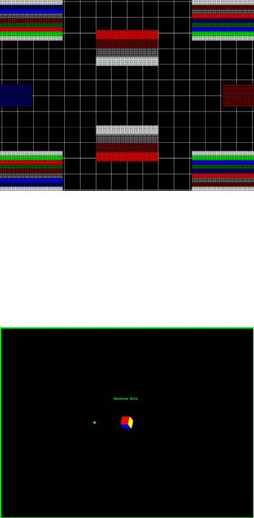
802BT/802R Video Test Generator User Guide 623
ComFocus
Description Special test image developed per customer specifications.
Cubes
Description This is an animated image consisting of one small multicolored cube orbiting around a
larger multicolored cube. Each cube also is spinning on its own axis. The default text string
is Quantum Data, which can be changed using commands. The primary version (shown
below) has a black background and a thick green border. The secondary version uses a
white background.
Purpose Can be used for show demonstrations with your own text.

624 Appendix B Image Reference
Custom
Description This image has a white border around the active video, a centered smaller yellow box, and
green diagonals.
Purpose This image is an example of some of the available drawing primitives. It is not intended to
be an image suitable for testing or adjusting a display. Rather, it can be used as a starting
point for developing a custom image of your own.
DeltaErr
Description Use with analyzer to test for flickering pixels in a static image. For more information, see
“Measuring pixel errors” on page 123.

802BT/802R Video Test Generator User Guide 625
Diamond1
Description Special test image developed per customer specifications.
Dot1606, Dot1610, Dot1612, Dot1615, Dot1812, Dot1815, Dot2016
Description The primary version has white pixel dots on a black background. The secondary version
has black pixel dots on a white background.
The primary version of the Dot2016 image is shown below.

626 Appendix B Image Reference
Dot_10, Dot_12, Dot_24
Description The active video area is filled with multiple rows of white, single pixel dots. The dots define
the corners of what would appear to be square boxes if all connecting pixels were lit. The
number of rows of boxes and the number of boxes per row depends on which version of
the image is selected and the screen aspect ratio of the currently-loaded format. The
number in the image’s name refers to the number of boxes that will be formed along the
minor axis for most aspect ratios. The generator calculates the ratio and then finds the
closest match from the following table.
The primary version has white pixel dots on a black background. A secondary version has
black pixel dots on a white background.
The primary version of the Dot_24 image is shown below.
Purpose To accurately produce an image on a color monitor, the three electron beams in the CRT
must meet (converge) at the same location at the same time. Small dots displayed on a
misconverged monitor appear as a group of multi-colored dots.
Aspect Ratio Dot_10 Dot_12 Dot_24
W : H Decimal Number
of Rows
Boxes per
Row
Number
of Rows
Boxes per
Row
Number
of Rows
Boxes per
Row
16 : 9 1.777 É 10 16 10 16 18 32
5 : 3 1.666 É 10 16 10 16 18 30
4 : 3 1.333 É 10 14 12 16 24 32
1 : 1 1.000 10 10 12 12 24 24
3 : 4 0.750 14 10 16 12 32 24
802BT/802R Video Test Generator User Guide 627
Method The convergence adjustments of most color monitors fall into two main categories. The
first set of adjustments, usually called Static Convergence, aligns the three beams in the
center of the display. This method involves turning on all three guns and adjusting the
various magnets on the convergence assembly to produce all white dots in the center of
the display. The convergence assembly is located on the neck of the CRT. Different
monitors and CRT types may each require their own magnet-adjustment sequence.
After the center of the display is properly converged, the outer areas are adjusted by using
the monitor’s Dynamic Convergence controls. The number of controls, the area of the
screen they affect, and their adjustment procedure depends on the monitor under test.
Test Focus adjustments
Purpose An out-of-focus monitor displays fuzzy pixels which, in turn, result in poorly formed and
hard-to-read characters.
Method On monitors with a single (static) focus adjustment, adjust the control for the best average
focus over the entire screen. The focus at certain locations should be within specified
limits.
Some monitors have a static and one or more dynamic focus controls. The sequence for
adjusting them and the areas of the screen they affect depend on the monitor under test.
DV_Swing
Description This image is only available with DVI and HDMI. The DV_Swing image is used to
temporally change the digital video swing (DVSS format parameter) between 90 and 1620
mVp-p of the HDMI and DVI digital output for the active format. This image displays the
current video swing value over a graduated (ramp) background. This image is supported
by HDMI boards (revision F or later), and DVI boards with FPGA F1 or later.
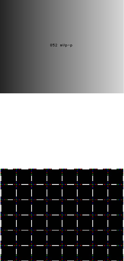
628 Appendix B Image Reference
Note: The DVSC command can be used to set the swing value between 150 and 1500
mVp-p.
Method To adjust the swing in 4 mV increments, press the Step key, then turn the Image knob.
Press the Step key again to reset the digital swing value to the default value, which is 1000
mVp-p for all formats.
Dyna
Description This image has multiple versions that display different sizes of the same pattern. Version 0
is shown below.


630 Appendix B Image Reference
EMITest1, EMITest2, EMITest3, EMITest4, EMITest5
Description Special test images used for electro-magnetic interference (EMI) testing of displays. The
entire active video area is filled with an “H” character. The primary versions of these
images draw white characters on a black background. The secondary versions draw black
characters on a white background. The EMITest1 image is shown below.
The EMITest2 image is the same as EMITest1, but with the bottom row of characters
constantly drawn left-to-right and then cleared.
The EMITest3 image is the same as EMITest1, but with a larger version of the “H”
character.
The EMITest4 image is the same as EMITest3, but with the bottom row of characters
constantly drawn left-to-right and then cleared.

802BT/802R Video Test Generator User Guide 631
The EMITest5 image is shown below.
FlashGry
Description This image flashes a flat gray image at a high-frequency rate.
The image flashed on the display is shown below.
FlashRGB
Description This image flashes RGB colors at a high frequency rate.

632 Appendix B Image Reference
The image used as a background on the display is shown below.
Flat, Flat07, Flat13, Flat20, Flat27, Flat33, Flat40, Flat47, Flat53, Flat60, Flat67,
Flat73, Flat80, Flat87, Flat93, FlatGray, Flat_01, Flat_02, Flat_03, Flat_04,
Flat_05, Flat_06, Flat_07, Flat_08, Flat_09, Flat_10, Flat_11, Flat_12, Flat_13,
Flat_14, Flat_15, Flat_16
Description The entire active video area is filled with a shade of gray. Each image displays a different
shade of gray. The FlatGray image is shown below.

802BT/802R Video Test Generator User Guide 633
Flat_B, Flat_G, Flat_R
Description The screen is filled with blue (B), green (G) or red (R). The Flat_B image is shown below.
Focus20
Description Primary version shown below. The secondary version has black characters on a white
background.

634 Appendix B Image Reference
FocusC14
Description Primary version shown below.The secondary version has black characters on a white
background.
FocusCCx
Description Primary version shown below. The secondary version has black characters on a white
background.

802BT/802R Video Test Generator User Guide 635
FocusEM
Description Primary version shown below. The secondary version has black characters on a white
background.
FocusEMP
Description Primary version shown below. The secondary version has black characters on a white
background.

636 Appendix B Image Reference
FocusM00 - FocusM15
Description The FocusM00 image is shown below.
Focus_@6, Focus_@7, Focus_@8, Focus_@9
Description In the primary versions, the screen is filled with white “@” characters on a black
background. The secondary versions are drawn with black characters on a white
background. The primary version of the Focus_@6 image is shown below.
Test Focus adjustments
Purpose An out-of-focus monitor displays fuzzy graphic images and poorly formed, hard-to-read
text characters.

802BT/802R Video Test Generator User Guide 637
Method On monitors with a single (static) focus adjustment, adjust the control for the best average
focus over the entire screen. The focus at certain locations of the screen should be within
specified limits.
Some monitors have a static and one or more dynamic focus controls. The sequence for
adjusting them and the areas of the screen that they affect depend on the monitor under
test.
Focus_Cx
Description In the primary version (shown below), the screen is filled with white Cx characters on a
black background. The secondary version is drawn with black characters on a white
background.
Test Focus adjustments
Purpose An out-of-focus monitor displays fuzzy graphic images and poorly formed, hard-to-read
text characters.
Method On monitors with a single (static) focus adjustment, adjust the control for the best average
focus over the entire screen. The focus at certain locations of the screen should be within
specified limits.
Some monitors have a static and one or more dynamic focus controls. The sequence for
adjusting them and the areas of the screen that they affect depend on the monitor under
test.

638 Appendix B Image Reference
Focus_H
Description In the primary version (shown below), the screen is filled with white H characters on a
black background. The secondary version is drawn with black characters on a white
background.
Test Focus adjustments)
Purpose An out-of-focus monitor displays fuzzy graphic images and poorly formed, hard-to-read
text characters.
Method On monitors with a single (static) focus adjustment, adjust the control for the best average
focus over the entire screen. The focus at certain locations of the screen should be within
specified limits.
Some monitors have a static and one or more dynamic focus controls. The sequence for
adjusting them and the areas of the screen that they affect depend on the monitor under
test.

802BT/802R Video Test Generator User Guide 639
Focus_MM
Description In the primary version (shown below), the screen is filled with white M characters on a
black background. The secondary version is drawn with black characters on a white
background.
Focus_Oo
Description In the primary version (shown below), the screen is filled with white Oo characters on a
black background. The secondary version is drawn with black characters on a white
background.
Test Focus adjustments
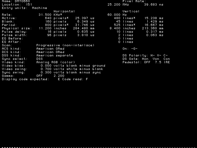
640 Appendix B Image Reference
Purpose An out-of-focus monitor displays fuzzy graphic images and poorly formed, hard-to-read
text characters.
Method On monitors with a single (static) focus adjustment, adjust the control for the best average
focus over the entire screen. The focus at certain locations of the screen should be within
specified limits.
Some monitors have a static and one or more dynamic focus controls. The sequence for
adjusting them and the areas of the screen that they affect depend on the monitor under
test.
Format
Description A listing of the data contained in any format. The primary image lists the settings of the
format driving the display. The secondary image can be used to list the contents of any
stored format (via the Location field).
This pattern works best at display resolutions of at least 640 pixel by 480 lines.
FormatRx
Description Used by analzyer to view timing parameters measured from external signal. For more
information, see “Measuring timing of video signal” on page 114.
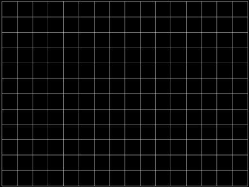
802BT/802R Video Test Generator User Guide 641
GenOps
Description Provides key sequences and status of special operating modes. For more information, see
“Special operating modes” on page 18.
GenStats
Description Provides detailed information about the generator. For more information, see “Displaying
system information” on page 44.
Geom_1 - Geom_5
Description The primary version of the Geom_1 image is shown below. Secondary version is drawn
with black lines on a white background.

642 Appendix B Image Reference
Gray25, Gray40
Description The Gray25 image is shown below.
GrayBar
Description The primary version (shown below) has 16 full-height vertical graybars. The intensity of
the bars is shown below. The secondary version splits the field into a top and bottom half.
The bars in the bottom half of the screen are in reverse order.
Test Video color tracking (color monitors)
Purpose To verify that a color monitor accurately reproduces colors at all intensities.

802BT/802R Video Test Generator User Guide 643
Method Perform the Brightness Control Adjustment and Brightness Uniformity tests first.
Changes in brightness from bar to bar should be uniform. All of the bars should appear as
an untinted gray at all levels.
Test Video gain linearity (monochrome monitors)
Purpose To check the video linearity (grayscale modulation)
Method Perform the Brightness Control Adjustment and Brightness Uniformity tests first.
Changes in brightness from bar to bar should be visible and uniform.
GrayL1, GrayL3
Description The GrayL1 image is shown below.
Grays5, Grays9, Grays11, Grays16, Grays32, Grays64
Description These images have the designated number of full-height vertical graybars.

644 Appendix B Image Reference
The Grays11 image is shown below.
GraysAll
Description Contains 256 grayscale versions, from 0 (full black) to 255 (full white).
Grill_11, Grill_15, Grill_22, Grill_33, Grill_44
Description The entire active video area is filled with alternating black and white stripes. The stripes
are drawn at different resolutions. Each of the stripes is four (4) pixels wide in the Grill_44
image and three (3) pixels wide in the Grill_33 image. Each of the stripes is two (2) pixels
wide in the Grill_22 image and one (1) pixel wide in the Grill_11 image.

802BT/802R Video Test Generator User Guide 645
The primary versions draw vertical stripes. The secondary versions draw horizontal
stripes. The primary version of the Grill_44 image is shown below.
Test Verify monitor resolution
Purpose The resolution of your monitor should meet or exceed the design specifications.
Method First adjust the brightness, contrast, and focus to their correct settings. You should be able
to see individual and distinct stripes in all areas of the display at all four resolutions. Failure
to see distinct lines at the highest resolution (Grill_11) may indicate you have a defective
video amplifier or picture tube.
Note: If multi-colored lines appear on a mask-type color picture tube, you may have a
problem with convergence or you may be exceeding the resolution of the picture tube.

646 Appendix B Image Reference
HalfArea
Description Primary version shown below. Secondary version is drawn with black boxes and white
background.
HalfClk
Description

802BT/802R Video Test Generator User Guide 647
Hat1606, Hat1610, Hat1612, Hat1615
Description Primary version of Hat1606 is shown below. Secondary version is inversed.
Hat1606A, Hat1610A, Hat1612A, Hat1615A
Description Primary version of Hat1606A is shown below. Secondary version is inversed.

648 Appendix B Image Reference
Hat1812, Hat1815
Description Primary version of Hat1812 is shown below. Secondary version is inversed.
Hat1812A, Hat1815A
Description Primary version of Hat1812A is shown below. Secondary version is inversed.

802BT/802R Video Test Generator User Guide 649
Hat2016
Description Primary version is shown below. Secondary version is inversed.
Hat2016A
Description Primary version is shown below. Secondary version is inversed.

650 Appendix B Image Reference
Hatch_6, Hatch_10i, Hatch_10o, Hatch_12i, Hatch_12o, Hatch_24i,
Hatch_24o, Hatch_24s, Hatch_G, Hatch_M, GRN_HTCH, and MAGENTA
Description The primary versions consist of a white, green (G and GRN), or magenta (M) crosshatch
drawn on a black background. The lines form square boxes. A single pixel dot is located in
the center of each crosshatch box. The number of boxes formed depends on the version
of the image selected and the screen aspect ratio of the currently loaded format. The
number in the image’s name refers to the number of boxes that are formed along the minor
axis for most aspect ratios. The generator calculates the ratio and then finds the closest
match from the table on the next page. Version names indicate the drawing method, as
follows:
• Versions ending in “i” draw from the inside (center) out. Any partial boxes are placed
around the perimeter of the image.
• Versions ending in “o” draw from the outside in. Any partial boxes are placed along the
centerlines of the image.
• Versions ending in “s” are the “i” version plus a 1-pixel thick border.
The secondary versions invert the images to black lines and dots on a white background.
Hatch_G, Hatch_M, GRN_HTCH and Magenta do not have secondary versions.
The primary version of the Hatch_10i image is shown below.
Aspect Ratio Dot_10 Dot_12 Dot_24
W : H Decimal Boxes
Vertically
Boxes
Horizon-
tally
Boxes
Vertically
Boxes
Horizon-
tally
Boxes
Vertically
Boxes
Horizon-
tally
16 : 9 1.777 É 10 16 10 16 18 32
5 : 3 1.666 É 10 16 10 16 18 30
4 : 3 1.333 É 10 14 12 16 24 32

802BT/802R Video Test Generator User Guide 651
Test Convergence adjustment (color monitors only)
Purpose To accurately produce an image on a color monitor, the three electron beams in the CRT
must meet (converge) at the same location at the same time. Lines displayed on a
misconverged monitor appear as several multi-colored lines, and the transitions between
different colored areas contain fringes of other colors.
Method The convergence adjustments of most color monitors fall into two main categories. The
first set of adjustments, usually called Static Convergence, aligns the three beams in the
center of the display. This method involves turning on all three guns and adjusting the
various magnets on the convergence assembly to produce all white dots in the center of
the display. The convergence assembly is located on the neck of the CRT. Different
monitors and CRT types may each require their own magnet adjustment sequence.
After the center of the display is properly converged, the outer areas are adjusted by using
the monitor’s Dynamic Convergence controls. The number of controls, the area of the
screen they affect, and their adjustment procedure depend on the monitor under test.
Hatch_16, Hatch_20
Description The primary version of the Hatch_16 image is shown below. The secondary versions draw
black lines on a white background.
1 : 1 1.000 10 10 12 12 24 24
3 : 4 0.750 14 10 16 12 32 24
Aspect Ratio Dot_10 Dot_12 Dot_24

652 Appendix B Image Reference
Hatch20
Description Primary version...The secondary version draws black lines on a white background.
Hatch4x3, Hatch5x4 and Hatch8x8
Description These are different versions of a crosshatch pattern that may be called for by some display
manufacturers’ test procedures. The primary version consists of white crosshatch and
circles on a black background. The secondary version inverts the image to black lines on a
white background.
The primary version of the Hatch4x3 image is shown below.
Purpose This is a general purpose test image that can be used to check and adjust video scan
linearity and geometry and color convergence.

802BT/802R Video Test Generator User Guide 653
Hatch64W
Description This is a crosshatch pattern that may be called for by some manufacturers’ test
procedures. The primary version (shown below) consists of an 8x8 white crosshatch on a
black background. A white rectangular patch is added in the center. The secondary
version inverts the image to black lines and box on a white background.
Purpose
Method This is a general purpose test image that can be used to check and adjust video scan
linearity and geometry, and color convergence. The large white rectangle also allows for
checking a display’s high voltage regulation. This is done by observing the vertical lines at
the left and right edges of the image. They should be fairly straight and not pull in the area
of the white rectangle.
HdcpA1B1, HdcpA1B2, HdcpA2B1, HdcpA2B2, HdcpProd
Description Used with HDCP feature. For more information, see Chapter 11, “Testing HDCP.”

654 Appendix B Image Reference
Hitachi1
Description Special test image developed per customer specifications. The image consists of a 2x2
cluster of Microsoft Windows® screen simulations using Japanese characters.
HSVnRGB
Description

802BT/802R Video Test Generator User Guide 655
Imex1
Description
InFocus1
Description Special test image developed per customer specifications.

656 Appendix B Image Reference
InFocus2
Description Special test image developed per customer specifications.
KanjiKAN
Description In the primary version (shown below), the screen is filled with white Japanese Kan
characters on a black background. The secondary version is drawn with black characters
on a white background.
Test Focus adjustments

802BT/802R Video Test Generator User Guide 657
LGLCDTVB, LGLCDTVG, LGLCDTVR, LGLCDTVW
Description Special test image developed per customer specifications. Each image has three versions.
The primary version of the LGLCDTVB image is shown below.
LGRamp
Description Special test image developed per customer specifications. The image provides a
grayscale of two objects. The secondary version of the LGRamp image is shown below.

658 Appendix B Image Reference
Linearty (Linearity)
Description This image has three parts. The first part consists of six (6) white circles. A large circle is
drawn in the center of the screen. Its diameter equals the lesser of the video height or
width of the display. A smaller circle is drawn at half the diameter and concentric with the
larger circle. A circle also is drawn in each of the corners of the screen. The diameter of
the corner circles equals one-fifth of the display width.
The second part of the image consists of a white crosshatch. The number of boxes in the
crosshatch depends on the physical size of the display.
The last part of the image consists of white tic marks on the horizontal and vertical center
lines of the image. The marks are one pixel thick at every other pixel location. Every fifth
mark is slightly longer. The color of the pattern can be changed with the individual video
output controls.
Test Linearity adjustment
Purpose To present an undistorted display, the horizontal and vertical sweeps of the electron beam
across the face of the CRT should be at uniform speeds. Any non-uniformity in the sweep
causes portions of an image to stretch while other portions are compressed. Non-linearity
in a monitor shows up in several ways. It may be present across the entire screen, in a
large portion of the screen, or localized in a very small area.
Method The circles in the image can be used to do a general adjustment of a monitor’s linearity
controls. Adjust the controls to form perfectly round circles. The crosshatch image can be
used to measure linearity and to make finer control adjustments. All the full boxes in the
crosshatch should be identical in size. Measure them with a ruler or a gauge made for the
monitor under test. Any deviation should be within your specification limits. Use the tic
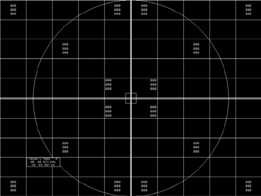
802BT/802R Video Test Generator User Guide 659
marks and a ruler or gauge to measure linearity over a small portion of the display.
Compare the number of tic marks per unit of measure with an adjacent or overlapping
area.
LinFocus
Description This image has several parts. The first part consists of a large circle in the center of the
screen. Its diameter equals the lesser of the video height or width of the display.
The second part is a 10x10 box crosshatch. The crosshatch is drawn in from the outside
edges, with any extra pixels in the boxes placed along the vertical and horizontal axis. The
vertical centerline is two pixels thick if the format has an even number of active pixels per
line. The horizontal centerline is two pixels thick if the format has an even number of active
lines per frame. A smaller box is added at the center of the image. The box is one-half the
height and two-fifths the width of one of the crosshatch boxes. Current format data is
shown in the lower left quadrant of the image. It shows the number of active pixels (H) and
lines (V) as well as the vertical and horizontal scan rates.
The primary version (shown below) consists of a white pattern on a black background. The
secondary version has a black pattern on a white background.
The image also includes blocks of focus-checking characters at various locations. The
blocks are positioned inside the crosshatch boxes and are up to 3x3 characters in size.
The size of the blocks is limited by the number of characters that can fit in one box.
Test Linearity adjustment
Method Please see the Linearity test image on “Linearty (Linearity)” on page 658 for information
on measuring linearity.
Test Focus adjustment
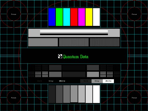
660 Appendix B Image Reference
Purpose An out-of-focus monitor displays fuzzy graphic images and poorly formed, hard-to-read
characters when text is displayed on the screen.
Method On monitors with a single (static) focus adjustment, adjust the control for the best average
focus over the entire screen. The focus at certain locations of the screen should be within
specified limits.
Some monitors have a static and one or more dynamic focus controls. The sequence for
adjusting them and the areas of the screen they affect depend on the monitor under test.
Master
Description

802BT/802R Video Test Generator User Guide 661
MoireX, MoireX33, MoireY, MoireY33
Description The MoireX and MoireY images consist of black lines on a white background across the
active video area. MoireX provides vertical lines; MoireY provides horizontal lines. The
MoireX image is shown below.
The primary version of the MoireX33 and MoireY33 images provide a black frame around
the black lines. The secondary version draws a white frame around black lines. The
primary version of the MoireX33 image is shown below.

662 Appendix B Image Reference
Monoscop
Description
MSony7, MSony8
Description Special test image developed per customer specifications. Primary version of the MSony7
image is shown below. The secondary version draws white boxes and characters with a
black background.

802BT/802R Video Test Generator User Guide 663
MulBurst
Description
Orion
Description This image provides a color bar that rotates (shifts) the bars to the right on an incremental
basis.
The color bars are shifted to the right at 3 second intervals. After pressing the Step key,
turn the Image knob to adjust the interval between 3, 10, 30 and 60 seconds.
Outline0, Outline1, Outline2, Outline3

664 Appendix B Image Reference
Description The primary version of the Outline0 image consists of a rectangular white border on a
black background. The border is one (1) pixel wide and defines the active video area. Two
(2) diagonal lines join the opposite corners. A-full size cross is centered in the image. The
horizontal line of the cross is one (1) pixel thick for formats with an odd number of active
lines and two (2) pixels thick for formats with an even number of active lines. The vertical
line of the cross is one (1) pixel thick for formats with an odd number of active pixels per
line and two (2) pixels thick for formats with an even number of active pixels.
The secondary version of these images draw black lines on a white background.
In the Outline1 version, the two diagonal lines are removed and short marker lines are
added to the border lines near to where the cross lines meet the border lines. The markers
appear at both sides of the cross lines. The distance between the marker lines and the
cross lines is the greater of either two (2) pixels or one (1) millimeter.

802BT/802R Video Test Generator User Guide 665
In the Outline2 version, the two diagonal lines are removed and short marker lines are
added to the corners, and where cross lines meet and end.
In the Outline3 version, the two diagonal lines are removed, cross lines are shortened, and
short marker lines are added.
Test Yoke tilt correction
Purpose The horizontal axis of a displayed image should line up with the horizontal axis of your
monitor. Any tilt is likely due to the yoke being rotated on the neck of the CRT. A rotated
yoke makes any displayed image appear rotated.
Method Place your monitor on a flat surface so the face of the CRT is perpendicular to the surface.
Use a ruler or gauge to measure the height of each end of the image’s horizontal center
line from the surface. The difference between the two readings should be within
666 Appendix B Image Reference
specification for the monitor. If it is out of specification, the yoke must be adjusted. Loosen
the hardware that clamps the yoke to the neck of the CRT and rotate the yoke until the line
is horizontal. Tighten the yoke-clamp hardware.
Test Yoke winding orthogonality check
Purpose The horizontal and vertical deflection coils on the yoke should have their axes cross at
exactly 90 degrees. Improper orientation of the windings causes displayed rectangles to
look more like nonorthogonal parallelograms. This type of defect is almost impossible to
correct with adjustments. It is usually easier to replace the defective yoke.
Method First, perform the yoke tilt correction described above. The vertical center line of the image
should be perpendicular to the work surface. If the deviation is beyond specification, the
monitor should be rejected and sent back for repair, rather than trying to magnet a
defective yoke.
Test Display size correction
Purpose A too-large active video size adjustment on a monitor may cause information to be lost
around the edges of the screen. A too-small active video size adjustment may make some
displayed information hard to read. The correct size is needed to obtain the correct aspect
ratio. You need the correct aspect ratio to get round circles and square squares.
Method First, determine the correct physical size of the active video area for the display. This
information usually is given in a display’s specification sheet or service manual. The size
should match the sizes in the format you are using. The size setting of the current format
can be checked using the Format test image.
Place a ruler or gauge along the horizontal line of the image and adjust the monitor's
horizontal size control until the distance between the end points matches the specified
value.
Move the ruler or gauge to the vertical line and adjust your monitor's vertical size control
until the distance between the end points matches the specified value.
Test Parallelogram distortion check
Purpose Parallelogram distortion is very difficult to correct with magnets because the correction
often causes barrel distortion. Therefore, you should decide early whether your monitor
meets this specification. The problem usually can be traced to the improper winding of the
yoke coils. If the problem is not too severe, it may be corrected by adding or adjusting
magnets on the yoke. However, if the distortion is excessive, it may be an indication of a
defective yoke which cannot be corrected with magnets.
802BT/802R Video Test Generator User Guide 667
Method Measure the lengths of the two (2) diagonal lines. Any difference is an indication of
parallelogram distortion. The difference in readings should be within the specifications of
the monitor.
If the difference in the readings is too far beyond specification, the monitor should be
rejected and sent back for repair, rather than trying to magnet a defective yoke.
Test Trapezoid distortion correction
Purpose This image gives you a way to measure trapezoid distortion in your monitor. If the
distortion is not too severe, you may be able to correct it by adding or adjusting magnets
on the yoke.
Method Perform the yoke winding orthogonality check and parallelogram distortion check first to
avoid wasting time on a monitor with a defective yoke.
Measure the width of the image at the top and bottom of the display. Any difference in
readings should be within the specification limits. Measure the height of the image at both
sides of the display. Again, any difference in readings should be within specification limits.
If either of the differences is out of specification, the trapezoid distortion of the monitor is
out of specification.
Add or adjust magnets on the yoke to correct the problem. The pin and barrel distortion
correction should be repeated to make sure that it is still in specification.
Test Pin and barrel distortion correction
Purpose If perfectly linear sweep signals are sent to a perfectly wound deflection yoke mounted on
a perfect CRT, you would not necessarily get a perfectly formed raster. Instead you would
likely get a raster that had its corners stretched away from the center, resembling a pin
cushion. This distortion occurs because the geometry of the deflected electron beam does
not match the geometry of the tube face plate. Also, imperfections in the yoke or CRT may
affect this problem. In some cases one or more corners may be pulled towards the center
of the raster causing it to look like a barrel. Uncorrected raster distortion carries over as
distortion of the displayed image.
Method A slot gauge may be used to determine if the amount of pincushion or barrel distortion is
within limits. A basic slot gauge may consist of a piece of opaque film with at least two (2)
transparent slots in it. One slot is used for top and bottom distortion and the other is used
for the sides. By positioning the correct slot over each portion of the border line, the entire
line should be visible. If this cannot be done at all four sides, the monitor requires
correcting.

668 Appendix B Image Reference
There are two main ways of correcting pincushion distortion. The first involves placing or
adjusting magnets on the yoke. This is a trial-and-error method. However, skilled operators
develop a feel for how strong a magnet to use and how to place it in order to get the
desired correction. If any correction is performed, the trapezoid distortion correction
should be repeated.
The other correction method involves adding correction signals to the deflection signal
driving the yoke. This method is usually found in color monitors, where adding magnets to
the yoke would cause problems with convergence and purity. The type and number of
adjustments depends on the monitor being tested.
P1
Description This image is a 6x6 white crosshatch without a border on a black background.

802BT/802R Video Test Generator User Guide 669
P2
Description This image is a 4x4 white crosshatch with a border on a black background.
P3
Description This image is a 4x4 white crosshatch with a border and a small, centered white patch on a
black background.

670 Appendix B Image Reference
P4
Description This image is an 8x8 white crosshatch with a border on a black background.
P5
Description This image is an 8x8 white crosshatch with a border and a small, centered white patch on
a black background.

802BT/802R Video Test Generator User Guide 671
P6
Description 16x12 pixel white crosshatch with a border on a black background.
P6_Sony
Description 6x12 pixel white crosshatch with a border on a black background.

672 Appendix B Image Reference
P7
Description 16x12 white crosshatch with a border and a small, centered white patch on a black
background.
P8
Description This image is an all black active video area. The secondary version draws an all white
video area.

802BT/802R Video Test Generator User Guide 673
P9
Description This image is an all white active video area. The secondary version draws an all black
video area.
P10
Description Special test image developed per customer specifications. There are four versions of this
image.
After pressing the Step key, turn the Image knob to select up to 4 different versions of this
image.
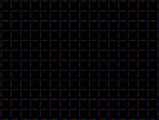
674 Appendix B Image Reference
PacketRx
Description Displays the InfoFrame data received by HDMI receiver. For more information, see
“Testing HDMI transmit device InfoFrame capability” on page 127.
PacketTx
Description Displays the InfoFrame data transmitted from the HDMI transmitter. For more information,
see “Viewing InfoFrame contents” on page 161.
PdsCrt1
Description Special test image developed per customer specifications.

802BT/802R Video Test Generator User Guide 675
PdsCrt2
Description Special test image developed per customer specifications.
Persist
Description In the primary version, 15 small white boxes move back and forth between diagonal guide
lines. The lines form 15 side-by-side tracks. The size of each box is scaled to the light
meter box size set by the MSIZ system parameter. The image does the following:
• The box in the center track (marked “1X”) moves one scan line vertically and one pixel
horizontally for each vertical frame of refresh.
• The seven boxes to the right of the center track (marked “2X” through “8X”) move 2, 3,
4, 5, 6, 7, and 8 pixels and lines per frame, respectively.
• The seven boxes to the left of the center track (marked “/2” through “/8”) move one scan
line vertically and one pixel horizontally for every 2, 3, 4, 5, 6, 7, and 8 vertical frames
of refresh, respectively. These boxes are at the bottom of the tracks.
In cases where the next move would cause the box to move beyond the end of its track, it
immediately reverses and moves the correct distance in the opposite direction for the next
frame.
A continuously-running counter appears in the upper left corner of the image. The number
shown is the number of vertical frame refreshes that have occurred since the generator
was first powered up.
The secondary version draws a black image on a white background.
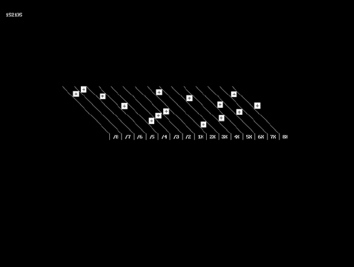
676 Appendix B Image Reference
An example of the primary version of the Persist image is shown below:
Test Phosphor persistence
Purpose The phosphors on the face of most CRTs continue to glow for a short period of time after
the electron beam has stopped energizing them. This phenomenon is called persistence.
A certain amount of persistence is desirable in most applications. It prevents a flickering of
a displayed image that most users would find objectionable. On the other hand, a CRT
with an overly long persistence time causes moving objects to leave a blurred trail.
Method A flickering in the slower moving boxes indicates that the combination of refresh rate and
phosphor persistence is not suitable for long-term viewing.
A fading tail left behind by the faster moving boxes indicates that the display may not be
suitable for viewing animated images.

802BT/802R Video Test Generator User Guide 677
PgBar64H, PgBar64V
Description Special test image developed per customer specifications. The PgBar64H image is shown
below.
PgCB, PgCG, PgCR, PgCW, PgCWrgb
Description Special test image developed per customer specifications. Primary version of PgCB is
shown below. The secondary versions draw all white over the last bar.
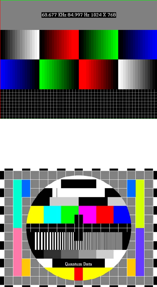
678 Appendix B Image Reference
The PGCWrgb is shown below.
Philips1
Description Special test image developed per customer specifications.
PixelRep
Description Used to test HDMI pixel repetition. There are 10 different versions of this image to support
the different pixel repetition settings. For more information, see “Testing HDMI video pixel
repetition” on page 152.

802BT/802R Video Test Generator User Guide 679
PRN24bit
Description This image displays pseudo-random noise using 24-bits-per-pixel color depth.
PRN_5, PRN_9
Description Used with analyer to verify the analyzer’s pseudo-random noise analysis capability. The
PRN_5 image introduces 5 pixel errors per color component, while the PRN_9 image
introduces 9 pixel errors per color component. For more information, see “Tes ti ng
accuracy of analyzer” on page 120.
The PRN_5 image is shown below.
‘
PulseBar
Description This image is intended for TV formats, but can be displayed with any format up to 100
MHz. The image looks like two vertical lines followed by a wide vertical bar on a display’s
screen. The first line is a sine-squared modulated pulse that fades from black to red and

680 Appendix B Image Reference
back to black. The pulse is 20 T for PAL and 12.5 T for NTSC formats. The second
narrower line is a 2 T white sine-squared pulse. T = 100 nSec for PAL and 125 nSec for
NTSC formats. The wide bar is white with sine-squared edges.
Test Video system testing
This multi-purpose pattern can be used with other instruments to check television K
factors. The modulated pulse can be used to check chrominance-to-luminance delay and
gain. The narrow white line can be used to measure short term linear distortion (K2T).

802BT/802R Video Test Generator User Guide 681
QuartBox
Description The primary version (shown below) has a single white box in the center of active video.
The size of the box is one-half the width and height of the active video area (a quarter of
the entire active video area). The secondary version draws a black box on a white
background.
Test Brightness control adjustment
Purpose The wrong brightness setting on your monitor may cause other tests such as Contrast,
Focus, and Beam Size to be invalid. An accurate brightness setting helps give repeatable
measurements throughout other tests. This version of the brightness box should be used if
the display’s specifications call for the brightness to be set with one-fourth of the screen lit.
Method Place your light meter probe within the center box and adjust the monitor’s brightness
control to obtain the required light meter reading.
Notes The color of the center box is a special color, named foreground. The FRGB command
can be used to change the default color of foreground to any RGB value.
IMGL quartbox: ALLU // loads QuartBox image
FRGB 122 122 122 // sets RGB color of box
After loading a different format, send the FRGB command again to set the box fill color.
If you want to draw your own box, use foreground as the fill color, and then use the FRGB
command to define the color of “foreground.” For example:
IMGL raster; ALLU // clears display
RECT foreground 100 100 100 100 dither100
FRGB 128 128 0
FRGB 192 192 64

682 Appendix B Image Reference
FMTL DMT0660; ALLU
FRGB 192 192 64
Ramp
Description This image provides an active video area starting from full black (+7.5 IRE) at one edge of
the screen to full white (+100 IRE) at opposite end of the screen.
There are 4 versions of this image—one for each edge of the display.
When selected, this image is displayed.
After pressing the Step key, turn the Image knob to change the image starting point to left,
right, top, or bottom.
RampX
Description This image provides a ramp image that continuously sweeps (moves) to the right on an
adjustable time basis.

802BT/802R Video Test Generator User Guide 683
When selected, this image is displayed.
After pressing the Step key, the image moves to the right. Adjust the speed using the
Image knob (turn clockwise to slow down the image).
Ramp_B, Ramp_G, and Ramp_R
Description The active video area goes from full black (+7.5 IRE) at the left edge of the screen to full
blue (_B), green (_G), or red (_R) at the right edge. The Ramp_B image is shown below.
Test Video gain linearity
Method When viewed on a TV screen, the full range of grays should be visible. There should be no
color shifts visible.

684 Appendix B Image Reference
Raster
Description The primary version shows a totally black display (nothing being displayed). The
secondary version shows a totally white display.
Test Raster centering
Purpose Many monitor applications require that the displayed image or text fit completely within a
bezel that surrounds the CRT. This usually requires that you first center the blank raster on
the face of the CRT, and then center the image within the raster. Use this image for
centering the raster on the CRT.
Method Turn up your monitor’s brightness control until the raster is just visible. Adjust the raster’s
position and size using the size and raster centering controls. The raster centering
adjustment for many monochrome monitors consists of moving magnetic rings on the
deflection yoke.
Regulate
Description The image cycles between two (2) patterns. In the primary version, the first pattern is a
white outline that defines the edges of displayed video. The other pattern has the same
outline plus a solid white rectangle in the center. The size of the solid rectangle equals
95% of the height and width of displayed video. The speed of the cycle cannot be
changed. The secondary version has a thick white frame with a black center for the first
pattern and a solid white active video area for the other pattern.

802BT/802R Video Test Generator User Guide 685
The first pattern of the primary version is shown below.
Test High voltage regulation
Method The size of the border should not change for each half of the image. The change in border
size between the two images should be within the specification limits of the monitor.
Samsung1, Samsung2
Description Special test images developed per customer specifications. The image consists of three
small simulations of Microsoft Windows® screens on a blue background (Samsung1) or
black background (Samsung2). A border and centered cross are formed with repeating
686 Appendix B Image Reference
groups of the characters “e” and “m”. The repeating characters are also used to form a
rectangular patch in the upper left hand corner and a circular area in the center of the
image. The secondary version of Samsung2 draws a white background.
Samsung3
Description Special test image developed per customer specifications.

802BT/802R Video Test Generator User Guide 687
Samsung4
Description Special test image developed per customer specifications.
Samsung5
Description Special test image developed per customer specifications.
Samsung6
Description Special test image developed per customer specifications.

688 Appendix B Image Reference
SamsungB
Description Special test image developed per customer specifications.
SamsungT
Description Special test image developed per customer specifications. There are four versions of this
image. When selected, the following image is displayed.
802BT/802R Video Test Generator User Guide 689
SlideBox
Description This image displays a 16x9 white crosshatch with a large white patch moving across the
screen.
To change the animation speed:
1. Load the SlideBox image.
2. Establish a terminal session with the generator (see page 14).
3. Enter the following commands:
ISUB 1
IVER 1
IMGU
DELX 10;
IMGU
DELX 20;
IMGU

690 Appendix B Image Reference
SlideX
Description This image displays a black background with a large white vertical bar moving across the
screen.
After pressing the Step key, the speed of vertical bar movement can be increased by
turning the Image knob (turn clockwise to speed up image).
To change the animation speed using the command-line interface:
1. Establish a terminal session with the generator (see page 14).
2. Load the SlideX image.
3. Enter the following commands:
ISUB 1
IVER 1
IMGU
DELX 10;
IMGU
DELX 20;IMGU
SMPTE133
Description This image is based on a recommended practice (RP-133) test pattern designed by the
Society of Motion Picture and Television Engineers (SMPTE). The original application was
used in testing and evaluating medical imaging monochrome displays. The image now is
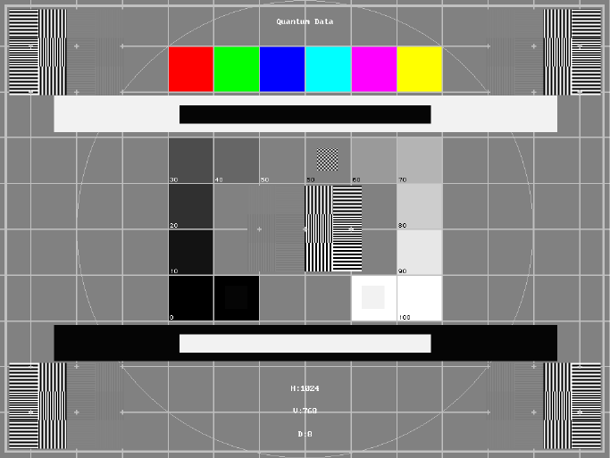
802BT/802R Video Test Generator User Guide 691
used in many different display applications. The image is self-scaling as to the number of
active pixels and active lines used. Some of the image’s elements have minor differences
from the original SMPTE specification.
These differences are noted in descriptions of the individual elements.
• The image is drawn on a reference background having a 50% intensity level. The
background covers the entire active video area.
•Crosshatch – There are 10 boxes vertically. The number of horizontal boxes is based
on the physical aspect ratio determined by the HSIZ and VSIZparameters in the
currently loaded format. The boxes are perfectly square with any fractional spaces
placed around the outside edges of the image. The vertical lines are two (2) pixels thick
while the horizontal lines are two (2) scan lines thick. Small crosses indicate the
intersection of the horizontal and vertical lines when they are covered by other parts of
the image. All parts of the crosshatch are normally drawn using a 70% intensity level.
A 75% level is used in the secondary version.
•Resolution patch – The patch is made up of six (6) smaller boxes that are each about
6.25% of the height of the display. The boxes are made of alternating intensity (0 and
100%) stripes. The stripes run vertically and horizontally. The stripes may be one (1),
two (2) or three (3) pixels wide each. Details of the patch are shown in the lower half of
the following illustration. The patches are located in each corner of the main image and
in the center. They are oriented with the highest resolution and contrast boxes closest
to the outside corners. The 48%-53%, 48%-51% and 50%-51% level patches are
omitted in the secondary version.
•Grayscale boxes – Twelve (12) boxes at eleven (11) intensity levels are clustered
around the center of the main image. They start at 0% and increase in 10% steps to
692 Appendix B Image Reference
100% with two (2) boxes at a 50% level. All of the grayscale boxes are omitted in the
secondary version.
•Gamma check dither box – A small box is drawn inside the right-hand 50% grayscale
box. The box is half the width and height of the larger box. The box consists of a
checkerboard of alternate one-on and one-off pixels. The alternate pixels have levels
of 0 and 100%. This smaller box is not part of the original SMPTE specification and is
omitted in the secondary version.
•Contrast boxes – Two (2) boxes are drawn adjacent to the grayscale boxes. They are
at 0 and 100% levels. There are smaller boxes drawn inside each box at 5 and 95%
levels. The contrast boxes are omitted in the secondary version.
•Black and white windows – Two (2) horizontal bars are located above and below the
grayscale boxes. Their height equals 8% of the display height. There are half-size bars
centered in the larger bars. In the primary version, the dark portion of the windows is
at a 5% level and the bright portion is at a 95% level. Zero and 100% levels are used
in the secondary version.
•Border – A border line is drawn around the image. It is set in from the edges of
displayed video a distance equal to 1% of the displayed height and has a thickness
equal to 0.5% of the displayed height. The intensity level is the same as that of the
crosshatch lines.
•Circle – A large circle is centered in the image. It touches the top and bottom of the
active video area when the aspect ratio is wider than it is high (landscape-type display).
The circle touches the left and right sides of active video when the aspect ratio is taller
than it is wide (portrait-type display). The intensity level is the same as that of the
crosshatch lines. The circle is not part of the original SMPTE specification.
•Resolution data - The number of active pixels per line and the number of active lines
is shown as text below the lower black and white window. The pixel depth also is shown.
The intensity level of the text is the same as that of the crosshatch lines. The displaying
of the data is not part of the original SMPTE specification.
The secondary version adds a row of six (6) color bars above and below the
black-and-white windows. The order of the colors, from left to right, is red, green, blue,
cyan (g+b), magenta (r+b) and yellow (r+g). The top row is drawn at 100% intensity
levels and the bottom row is drawn at 50% intensity levels. Color bars are not part of
the original SMPTE specification.
Test Deflection linearity
Method If the overall height and width of the display’s active video area match the sizes in the
format, the large circle should be perfectly round. Each box in the crosshatch pattern
should be the same size and shape. For more information on testing linearity, refer to the
Linearty test image on page 658.
802BT/802R Video Test Generator User Guide 693
Test High contrast resolution
Method All the 0 and 100% level stripes in all the resolution patches should be separate and
distinct.
Test Low contrast resolution and noise
Method All the mid-level 2 on - 2 off stripes in all the resolution patches should be visible and
distinct. This is a sensitive test for noise in the display’s video amplifiers.
Test Quick gamma check
Method The average brightness level of the small gamma dither box should match the brightness
of the larger surrounding box. This is a visual check to see if the display’s gamma
correction is producing the correct mid-level response.
Test Video gain linearity and gamma
Method The individual grayscale boxes all should be at their indicated levels. A small aperture
photometer is usually required to get accurate and repeatable readings.
Test Contrast and brightness check
Method On a display with properly adjusted brightness and contrast controls, both the 5% and
95% contrast boxes should be clearly visible inside their larger surrounding 0% and 100%
boxes.
Test Video amplifier stability
Method The two black-and-white windows should show sharp transitions between the smaller box
and the surrounding window. Streaking may be an indication of undershoot or overshoot
while ghost images may indicate a ringing problem.
Test Excessive overscan and off-center alignment
Method The entire border should be clearly visible on the face of the tube and not be hidden by the
edge of the glass or by any bezel.
Test Interlace flicker
694 Appendix B Image Reference
Method The horizontal 1 on - 1 off stripes in the resolution boxes should not have objectionable
flicker when shown with an interlaced format. Excessive flicker indicates that the
combination of the display’s CRT persistence and frame scan rate is below the persistence
time of the human eye.
SMPTEbar
Description This image is based on an engineering guideline (EG1-1990) test signal specified by the
Society of Motion Picture and Television Engineers (SMPTE). The SMPTE pattern, in turn,
is derived from an EIA standard test pattern (RS-189-A). The image, is set up to be
generated by an 801GX generator as an encoded TV output. It is designed for adjusting
the color settings of a television monitor by eye. It can also be used with a TV waveform
analyzer and vectorscope for testing video signal processors and color decoders. The
image is available on all models as a component RGB signal. Some of the image’s
elements have some differences from the original SMPTE specification.
These differences are given in descriptions of the individual elements.
• The upper 67% of the image consists of a series of color bars. These bars match the
order of the bars in the SMPTE and EIA patterns. They are similar to the 801GX’s
TVBar_75 image without the last black bar.
• The left side of the lower 25% of the image contains isolated -I and Q color difference
signals that match the original EIA and SMPTE patterns. The -I signal appears as a
bluish-gray bar and the Q signal appears as a purple bar on a TV monitor. The bars are
separated by a white (+100 IRE) bar.
• The right side of the lower 25% of the image contains a narrow 12.5 IRE gray bar. Due
to a hardware limitation on the 801GX, this portion of the pattern does not match the
original EIA and SMPTE patterns. The original patterns had +3.5 (blacker than black)
and +11.5 IRE bars separated by a +7.5 IRE (black) bar.

802BT/802R Video Test Generator User Guide 695
• The remaining central 8% of the image contains a row of chroma set bars. These bars
are part of the SMPTE pattern but are not in the EIA pattern. The order of the
alternating color and black bars matches those in the SMPTE pattern.
Test Color video performance
Purpose This general purpose pattern can be used to check the video handling capabilities of most
parts of a television system.
Method When viewed on a TV screen, all of the upper color bars should be correct and in the order
shown. The hue and intensity of each bar should be uniform over the entire bar.
The image can be used with a TV waveform analyzer to check the performance of a video
system. The upper color bars, as they would appear on a waveform analyzer, are shown
on a previous page.
Test Color decoder performance
Purpose The image can used with a TV vectorscope to check for proper operation of a video color
decoder. Vectorscope signatures of the upper and lower portions of the image using
NTSC encoding can be found on the previous page.
Method The vectorscope signature for the color bars should hit the target test point for each color
on the vectorscope’s graticule. If you are using PAL encoded video, the signature will be
similar to the one shown for the TVBar_75 test image on page page 702.
The three “legs” of the vectorscope signature for the -I and Q color difference signals
should match the Burst, -I and Q reference lines on the vectorscope’s graticule.
The following tests are based on the original SMPTE guideline:
696 Appendix B Image Reference
Test Visual chroma gain adjustment
Method To perform this test, you must have a way of turning off the red and green guns in the
monitor under test. Turning off the red and green video components of the 801GX
generator’s video output will not work for this test.
This test uses the upper and central color bars. Switch off the red and green guns on the
monitor. This will produce four blue bars, separated by black bars. Adjust the chroma gain
so that the brightness of each outer blue bar is uniform over the entire bar. The gain is
correct when the bottom 10% of each bar is the same brightness as the rest of the bar.
Test Visual chroma phase adjustment
Method In order to perform this test, you must have a way of turning off the red and green guns in
the monitor under test. Turning off the red and green video components of the 801GX
generator’s video output will not work for this test.
This test uses the upper and central color bars. Switch off the red and green guns on the
monitor. This will produce four blue bars, separated by black bars. Adjust the chroma
phase so that the brightness of each of the two central blue bars is uniform over the entire
bar. The phase is correct when the bottom 10% of each bar is the same brightness as the
rest of the bar.
Test Visual black level adjustment
Method This test uses the lower right hand portion of the image. Reduce the black level until the
gray bar disappears. Slowly increase the black level until the bar just becomes clearly
visible.

802BT/802R Video Test Generator User Guide 697
Sony6
Description Special test image developed per customer specifications.
Sony6WLC
Description Special test image developed per customer specifications.

698 Appendix B Image Reference
sRGBflat
Description For testing color response per Microsoft’s WinColorKit standard. This standard was
developed by Microsoft to standardize methods relating to the matching of colors
appearing on various displays (go to
http://www.microsoft.com/whdc/hwdev/tech/color/ColorTest.mspx for more details). There
are 38 different versions of this image to support this feature.
When selected, a flat image appears with a color that is remembered from the last time
the image was set up. The example below shows version 8 (Red1) of the sRGBflat image:
A small label in the upper left corner of the image indicates the Microsoft name for the
color that is currently being displayed (for example, “sRGB-Gray5”). Note that some of the
names that appear conflict with generator color names (for example, “sRGB-Gray5” is not
the same as the generator color “Gray5”).
After pressing the Step key, turn the Image knob to select up to 38 different versions of
this image. Each image displays another WinColorKit color.
Note: For more information of generator support for Microsoft WinColorKit, go to
http://www.quantumdata.com/support/kb/article.asp?kbid=100152.
Staircas, Stairs20
Description The active video area goes from full black at the left edge of the screen to full white at the
right edge. There are six (6) steps (Stairs20) or sixteen (16) steps (Staircas).

802BT/802R Video Test Generator User Guide 699
The Stairs20 image is shown below.
Test Video gain linearity
Method When viewed on a monitor’s screen, a black bar plus five (5) gray bars should be visible.
There should be no color shifts, and each of the bars should be uniform in color.
The image also can be used with an oscilloscope or TV waveform analyzer to check the
gain linearity and gamma correction of a video system.
Strokes0, Strokes1
Description This image may cited by some display manufacturers’ test procedures. The Strokes0
version consists of multiple groups of separated red, green and blue horizontal lines drawn
on a black background. The Strokes1 version consists of multiple groups of separated red,
green and blue diagonal lines drawn on a black background.

700 Appendix B Image Reference
The Strokes0 image is shown below.
Purpose These images are special-purpose test patterns used in test and alignment procedures
specified by some display manufacturers.
Text_9, Text_9T, Text_11, Text_12T, Text_16
Description In the primary versions, the screen is filled with random paragraphs of white text on a
black background. The amount of text is determined by the size of the font used and the
horizontal and vertical resolution of the format. The Text_16 image uses a larger font than
the Text_9 image. The secondary versions use black text on a white background.
The primary version of the Text_9 image is shown below.
Test Word processor simulation

802BT/802R Video Test Generator User Guide 701
Purpose If your monitor is used in word processor workstations or other applications that call for
large amounts of text to be displayed, you can use this image to simulate actual user
conditions.
Method Select a suitable font size and text color. Adjust your monitor’s brightness and contrast
controls to obtain the best image. The characters in all areas of the display should be well
formed and in focus.
TintAlign
Description
Toshiba
Description Special test image developed per customer specifications. There are two sub images, the
secondary image is depicted below. The top half of the image has three small boxes (red,
green, blue) with the upper left half at 92.7% luminence and the upper right half at 50%

702 Appendix B Image Reference
luminence. There is a series of 11 small boxes of increasing luminence left to right with the
luminence identified in text. The lower left quarter of the image is 28.5% luminence and
the lower right is magenta at 44.3 IRE.
TVBar100 & TVBar_75 (TV formats only)
Description The image consists of seven vertical bars that fill the entire active video area. The color
and order of the bars is shown in the figure below. The TVBar100 image has a peak video
level of 100 IRE and the TVBar_75 image has a peak video level of 75 IRE.
The TVBar100 image is shown below.
Test Color video performance

802BT/802R Video Test Generator User Guide 703
Purpose This general purpose pattern can be used to check the video handling capabilities of most
parts of a television system.
Method When viewed on a TV screen, all of the colors should be correct and in the order shown.
The hue and intensity of each bar should be uniform over the entire bar.
The image can be used with a TV waveform analyzer to check the performance of a video
system. Individual scan lines of each image, as they would appear on a waveform
analyzer, are shown on the following page.
The image is quite effective when used with a TV vectorscope to see how a video system
handles an encoded color signal.The image consists of a white crosshatch on a black
background. The lines form square boxes when the display’s active video area has a 4:3
aspect ratio. The vertical lines are made using sine-squared (2 T) pulses (T = 125 nSec for
NTSC and T = 100 nSec for PAL).
Test Convergence adjustment
Purpose To accurately produce an image on a color monitor, the three electron beams in the CRT
must meet (converge) at the same location at the same time. Lines displayed on a
mis-converged monitor will appear as several multi-colored lines, and the transitions
between different colored areas will contain “fringes” of other colors.
Method The convergence adjustments of most color monitors can be divided into two main
categories. The first set of adjustments, usually called “Static Convergence,” calls for
aligning the three beams in the center of the display. This method involves turning on all
three guns and adjusting the various magnets on the convergence assembly to produce
all white lines and dots in the center of the display. The convergence assembly is located
on the neck of the CRT. Different monitors and CRT types may each require their own
magnet adjustment sequence.

704 Appendix B Image Reference
After the center of the display is properly converged, the outer areas can be adjusted by
using the monitor’s “Dynamic Convergence” controls. The number of controls, the area of
the screen that they affect and their adjustment procedure is dependent upon the monitor
under test.
Test Sweep linearity adjustment
Purpose To present an undistorted display, the horizontal and vertical sweeps of the electron beam
across the face of the CRT should be at uniform speeds. Any non-uniformity in the sweep
will cause portions of an image to be stretched while other portions will be compressed.
Non-linearity in a monitor can show up in several ways. It may be present across the entire
screen, a large portion of the screen, or it may be localized in a very small area.
Method Adjust the display’s linearity controls so that all of the boxes in the crosshatch are identical
in size. You can measure the boxes with a ruler or with a gauge made for the monitor
under test. Any deviation should be within your specification limits.
Taffeta
Description
TVoutLin
Description Equivalent to Outline1 image but it uses anti-aliasing for vertical bars and double
horizontal lines, which reduces flickering.

802BT/802R Video Test Generator User Guide 705
TVSplBar
Description Special test image developed per customer specifications.
706 Appendix B Image Reference
708 Appendix C Error Messages
System errors
This section discusses system error messages that may be displayed by the generator
from time to time.
Power-on self test messages
The integrity of the data stored in non-volatile memory is checked every time the generator
is turned on. The following tests are performed:
1. The system configuration memory is checked. The memory remembers what the
generator was doing when it was last powered down. The memory also stores all
system wide parameters such as calibration factors and the light meter size. It is also
checked to see if it is compatible with the current version of operating firmware. If
everything is in order, then the generator goes on to step 2.
Otherwise, a “System corrupt!” message is displayed for 2 seconds. This message is
immediately followed by a “Memory blank” message, which is displayed for 2 seconds
while the format memory is re-initialized. Memory initialization involves clearing the
entire non-volatile memory and loading it with factory default data. Any and all data
created or edited by the user will be wiped out. The calibration factors are restored to
the original values used at the factory to test and calibrate the unit. The generator then
continues with step 3.
Note: System corruption is rare, and may be an indication of a bad memory backup
battery or a damaged generator.
Note: If you update the firmware EPROM in your unit, your system will appear to be
corrupt at the next power-on.
2. The remainder of non-volatile memory is checked to see if any data has been corrupted
since the last time the generator was used. This check includes each of the 300 format
storage locations. All user created custom images and test sequences are also
checked. If no problems are found, the generator goes on to step 3.
If one (or more) items have been corrupted, a message containing a tally of the
defective items is displayed for 2 seconds. A message for two corrupted items is shown
here. Please note that the checking routine does not identify the types of items (format,
802BT/802R Video Test Generator User Guide 709
custom image or test sequence) that are corrupted. It is up to the user to check the
contents of the individual items. Attempting to load a corrupted item will report and error
for that item.
A corrupted format can be repaired be either editing it or by downloading a new set of
data from a computer.
In most cases, a corrupted custom image or test sequence can not be repaired. This is
due to the variable data structure used. You will need to recreate and save the data
back into memory.
Repeated corruption of the data in non-volatile memory usually indicates a weak
battery. Battery replacement information can be found in the chapter on Maintenance.
3. A power-on message, indicating the current firmware and hardware revision levels, will
appear for 2 seconds at the end of the self test procedure.
If an animated image is displayed at power on, this message will not disappear until a
button is pushed or a knob is turned.
Power fail message
Whenever the AC power line voltage dips below the minimum specified, this message is
displayed and the generator’s microprocessor is halted.
If you see this message during normal operation, it probably indicates that a power sag or
short duration drop-out has occurred. To clear this condition, cycle the power going to the
generator. If the power is good, the generator should resume normal operation. If you still
have a problem, you may also want to check to see that the line voltage selector (next to
the power inlet) is set correctly for the power being fed into the generator.
710 Appendix C Error Messages
Format errors
Under normal operating conditions, a properly programmed model 801GX generator
should never report any Format error messages. If you do get an error message while
loading a format it is for one of two reasons. The generator distinguishes between invalid
data, entered in one of the programming modes, and corrupted data caused by a memory
failure. In either case, the generator will shut all of its outputs off. The outputs remain off
until a valid format is loaded.
Invalid data error messages
The example on the left shows a typical invalid data error message. The top line of the
display shows the format’s storage location number and name. The bottom line shows the
error number. Error numbers will be in the range of 2000 through 2999. Different numbers
indicate what type invalid data or combination of data is causing the error.
The following pages explain the cause of each of the error numbers and offers
suggestions on how to correct the problem.
Corrupt data error messages
The example on the left shows a corrupted data error message. The top line of the display
shows the format’s storage location number and name. The bottom line shows the error
number. Error number 9450 identifies the cause of the error as corrupted data. This type
of error either indicates the signs of a failing memory backup battery or a more serious
hardware failure in the generator.
Corrupted formats can corrected by either editing them or by downloading a clean copy of
the format from a computer. The “Programming” chapter explains both methods in detail.
802BT/802R Video Test Generator User Guide 711
Error code descriptions
2000-2999 Format errors
2030 Number of fields per frame less than 1
A valid video format must have at least one (1) vertical filed of video per frame.
2040 Number of fields per frame greater than 2
The generator hardware configuration does not support interlaced video formats having
more than two (2) vertical fields per frame.
2041 Can not repeat field if progressive
Repeat field operation is only supported in interlaced video formats.
2050 Horizontal total too small
The video format’s total (active + blanked) number of pixel clock cycles per horizontal scan
line is below the minimum number supported by the generator hardware configuration.
2060 Horizontal total too large
The video format’s total (active + blanked) number of pixel clock cycles per horizontal scan
line is greater than the maximum number supported by the generator hardware
configuration.
2071 Pixel rate too high
The video format’s total (active + blanked) number of pixel clock cycles per horizontal scan
line multiplied by the horizontal scan rate exceeds the maximum pixel clock frequency
supported by the generator hardware configuration for the format’s video type.
2072 Pixel clock rate too high for pixel depth
The video format’s pixel depth combined with the total (active + blanked) number of pixel
clock cycles per horizontal scan line and horizontal scan rate exceeds the maximum
internal video data bit rate supported by the generator hardware configuration. The pixel
depth and/or total number of pixels per line need to be reduced in order to keep the current
horizontal scan rate.
2073 Pixel rate justification too high
The target pixel clock rate selected for justification of the video format exceeds the
generator hardware configuration.
2074 Pixel depth not supported
The video format’s pixel depth is not supported by the generator hardware configuration.
712 Appendix C Error Messages
2075 Analog composite sync type not supported
The video format’s analog video composite sync type selection is not supported by the
generator hardware configuration.
2076 Digital sync composite type not supported
The video format’s digital composite sync type selection is not supported by the generator
hardware configuration.
2077 Number of digital links not allowed
The number of serial digital video data links in the video format exceeds the number of
links supported by the current firmware.
2078 Digital sync separate type not allowed for HDTV formats
The generator hardware configuration does not support digital separate sync for the
specific video type selection in the video format
2079 Number of links not supported
The number of serial digital video data links in the video format exceeds the number of
links supported by the generator hardware configuration.
2080 Pixel rate too low
The video format’s total (active + blanked) number of pixel clock cycles per horizontal scan
line multiplied by the horizontal scan rate is less than the minimum pixel clock frequency
supported by the generator hardware configuration for the format video type.
2082 Number of bits not allowed
The generator hardware configuration does not support the number of data bits per color
for the serial digital video type selected in the video format.
2083 Invalid quantizing mode
An invalid value has been specified for the DVQM parameter.
2084 Invalid Pixel Repetition
In digital mode, double clocking is not supported for this specific hardware. This error may
be the result of an older FPGA or hardware.
2085 Invalid Sampling Mode
The value specified for DVSM is not valid and is inconsistent with the setting of DVST.
2090 Horizontal total not even
The generator hardware configuration does not support interlaced video formats with a
total (active + blanked) number of pixel clock cycles per horizontal scan line that is not
evenly divisible by 2.
802BT/802R Video Test Generator User Guide 713
-OR-
The generator hardware configuration does not support a video format with a total (active
+ blanked) number of pixel clock cycles per horizontal scan line that is not evenly divisible
by 2 for the selected analog or digital composite sync type.
2091 Horizontal total not a multiple of 4
The generator hardware configuration does not support a video format with a total (active
+ blanked) number of pixel clock cycles per horizontal scan line that is not evenly divisible
by 4. Mostly applies to video formats using serial digital video.
2092 Horizontal resolution not even
Number of active pixels per line must be evenly divisible by 2 for the given video format
type and generator hardware configuration.
2093 Horizontal sync pulse width not even
Number of pixel clock cycles in the horizontal sync pulse width must be evenly divisible by
2 for the given video format type and generator hardware configuration.
2094 Horizontal sync pulse delay not even
The number of pixel clock cycles in the horizontal sync pulse delay must be evenly
divisible by 2 for the given video format type and generator hardware configuration.
2096 Horizontal resolution not a multiple of 4
The generator hardware configuration does not support a video format with a number of
active pixels per horizontal scan line that is not evenly divisible by 4. Mostly applies to
video formats using serial digital video.
2097 Horizontal sync pulse width not a multiple of 4
The generator hardware configuration does not support a video format with the number of
pixel clock cycles in the horizontal sync pulse width not evenly divisible by 4. Mostly
applies to video formats using serial digital video.
2098 Horizontal sync pulse delay not a multiple of 4
The generator hardware configuration does not support a video format with the number of
pixel clock cycles in the horizontal sync pulse delay not evenly divisible by 4. Mostly
applies to video formats using serial digital video.
2099 JRAT greater than 200MHz not allowed
The 802BT generator does not support a setting of JRAT greater than 200MHz.
714 Appendix C Error Messages
2130 Horizontal active too small
The number of active pixels per horizontal scan line is less than the minimum supported
by the generator hardware configuration.
2140 Horizontal blanking too small
The video format’s horizontal blanking period expressed in microseconds and/or number
of pixel clock cycles is not supported by the generator hardware configuration.
2141 Horizontal blanking too small
Same as Error number 2140. Found in some firmware releases for different generator
hardware configurations.
2150 Horizontal blanking too small
Same as Error number 2140. Found in some firmware releases for different generator
hardware configurations.
2151 Horizontal total less than horizontal resolution
The video format’s total (active + blanked) number of pixel clock cycles per horizontal scan
line can not be less than the number of active pixels per scan line.
2152 Horizontal resolution too large or Horizontal blanking too small
Same as Error number 2140. Found in some firmware releases for different generator
hardware configurations.
2155 Horizontal blanking too small
Same as Error number 2140. Found in some firmware releases for different generator
hardware configurations.
2180 Horizontal pulse width too small
The generator hardware configuration does not support video formats having horizontal
sync pulse widths less than one pixel clock cycle long.
2181 Horizontal sync pulse width not even
Number of pixel clock cycles in the horizontal sync pulse width must be evenly divisible by
2 at the current pixel clock rate for the video format and generator hardware configuration.
2190 HSPW too small for HDTV sync
The generator hardware configuration does not support video formats having horizontal
sync pulse widths less than two pixel clock cycles long for the current video and HDTV
sync type selections.
802BT/802R Video Test Generator User Guide 715
2191 HSPW must be even for HDTV sync
The number of pixel clock cycles in the horizontal sync pulse width must be evenly
divisible by 2 for the current video and HDTV sync type selections.
2200 Horizontal pulse width too large
The generator hardware configuration does not support a horizontal sync pulse width that
is greater than the horizontal blanking period.
2201 Horizontal pulse delay not even.
The number of pixel clock cycles in the horizontal sync pulse delay must be evenly
divisible by 2 at the current pixel clock rate for the video format and generator hardware
configuration.
2205 Frame sync pulse width too small
The generator hardware configuration does not support a Frame Sync pulse width less
than horizontal scan period.
2206 Frame sync pulse width too large
The Frame Sync pulse width can not be greater than the total (active + blanked) number of
horizontal scan lines in one frame of video.
2207 Probe sync pulse width too small
The probe sync pulse width is less than minimum supported by the generator hardware
configuration.
2208 Probe sync pulse width too large
The probe sync pulse width is greater than maximum supported by the generator
hardware configuration.
2230 Horizontal pulse delay extends sync beyond blanking
The generator hardware configuration does not support the video format’s combination of
horizontal sync pulse delay and pulse width that places any portion of the horizontal sync
pulse outside of the horizontal blanking period.
2231 Vertical serration adjustment too big
The video format’s HVSA setting beyond the maximum limit for the video type selected
and generator hardware configuration.
2240 Vertical total too small
The total (active + Blanked) number of horizontal scan lines per frame a progressive scan
(non-interlaced) video format is lees than the minimum supported by the generator
hardware configuration.
716 Appendix C Error Messages
2250 Vertical total too small for interlaced format
The total (active + blanked) number of horizontal scan lines per frame is less than the
minimum number supported by the generator hardware configuration.
2270 Vertical total is even
The generator hardware configuration does not support interlaced scan video formats
having an even total (active + blanked) number of horizontal scan lines per frame.
2280 Vertical total too large
The total (active + blanked) number of horizontal scan lines per frame exceeds the
maximum limit for the generator hardware configuration.
2300 Vertical active too small
The active number of horizontal scan lines per frame of a progressive scan
(non-interlaced) video format is less than the minimum supported by the generator
hardware configuration.
2310 Vertical blanking too small
The number of blanked horizontal scan lines per frame for a progressive scan
(non-interlaced) video format is less than the minimum supported by the generator
hardware configuration.
2320 Vertical active too small for interlaced format
The active number of horizontal scan lines per frame of an interlaced video format is less
than the minimum supported by the generator hardware configuration.
2321 Vertical active not even
The generator hardware configuration does not support interlaced scan video formats
having an odd active number of horizontal scan lines per frame.
2330 Vertical blanking too small for interlaced format
The number of blanked horizontal scan lines per frame for an -interlaced video format is
less than the minimum supported by the generator hardware configuration.
2350 Vertical pulse too small
The vertical sync pulse width is less than the minimum supported by the generator
hardware configuration.
2370 Vertical pulse too large
The vertical sync pulse width is greater than the maximum supported by the generator
hardware configuration.
802BT/802R Video Test Generator User Guide 717
2390 Vertical pulse too large for interlaced format
The vertical sync pulse width combined with the number of pre and post-equalization
pulses for an interlaced format is greater than the maximum supported by the generator
hardware configuration.
2391 Incompatible analog composite sync & digital composite sync types
The generator hardware configuration does not support the video format outputting both
analog composite sync and digital composite sync type selections at the same time.
2392 Incompatible analog composite sync & digital separate sync types
The generator hardware configuration does not support the video format outputting both
analog composite sync and digital separate sync type selections at the same time.
2393 Analog composite sync type not compatible with analog video type
The generator hardware configuration does not support the video format’s analog
composite sync type being added to the current analog video type.
2394 ACS available on green only
The generator hardware configuration supports adding analog composite sync to only the
green analog video output
2395 Sync type selection incompatible with analog video type selection
The video format’s analog video type selection requires the use of analog composite sync.
2396 Invalid analog composite sync type
The current firmware does not support the format’s analog composite sync type parameter
value (ASCT setting) or the generator hardware configuration does not support a video
format’s analog composite sync type for non-interlaced operation.
2397 Invalid digital composite sync type
The current firmware does not support the format’s digital composite sync type parameter
value (DSCT setting) or the generator hardware configuration does not support a video
format’s digital composite sync type for non-interlaced operation.
2398 Invalid digital separate sync type
The current firmware or generator hardware configuration does not support the format’s
digital separate sync type parameter value (DSST setting)
2399 Invalid sync type selection
The current firmware does not support the format’s active sync type selection (SSST
setting).
718 Appendix C Error Messages
2400 Analog composite sync type and digital separate sync type incompatible
The generator hardware configuration does not support analog composite sync and digital
separate sync being active at he same time for the given analog composite sync type
parameter value (ASCT setting) and digital separate sync type parameter value (DSST
setting).
2401 Invalid horizontal sync pulse delay
The generator hardware configuration does not support the format’s current horizontal
sync pulse delay setting
2405 Frame sync pulse delay negative
The video format’s frame sync pulse delay setting must be zero or a positive number.
2406 Frame sync pulse delay too large
The video format’s frame sync pulse delay setting exceeds the maximum limit supported
by the generator hardware configuration.
2407 Negative probe sync pulse vertical delay
The video format’s probe pulse vertical delay setting must be zero or a positive number.
2408 Probe sync pulse vertical delay too large
The video format’s probe pulse vertical delay setting exceeds the maximum limit
supported by the generator hardware configuration.
2409 Negative probe sync pulse horizontal delay
The video format’s probe pulse horizontal delay setting must be zero or a positive number.
2410 Probe sync pulse horizontal delay too large
The video format’s probe pulse horizontal delay setting exceeds the maximum limit
supported by the generator hardware configuration.
2425 Sync type selection not supported
The current firmware does not support the video format’s active sync type selection (SSST
setting) or the active sync type selection is not supported by the current analog video type
selection (AVST setting).
2430 Vertical pulse delay extends sync beyond blanking
The generator hardware configuration does not support non-interlaced video formats
having a vertical sync pulse period greater that the vertical blanking period
2450 Vertical pulse delay extends sync beyond blanking
The generator hardware configuration does not support interlaced video formats having a
vertical sync pulse period greater that the individual blanking periods between the fields.
802BT/802R Video Test Generator User Guide 719
2465 Pixel clock pulse gate = 1 and pixel depth = 8
The generator hardware configuration does not support outputting a pixel clock output
when the video format’s pixel depth is eight bits-per-pixel.
2466 Pixel clock pulse gate = 1 not allowed
The generator hardware configuration does not support a pixel clock output.
2490 EQ before too large
The video format’s number of lines of pre-equalization for analog or digital composite sync
must not exceed the number of lines of vertical sync pulse delay.
2495 EQ after too large for interlaced format
The interlaced video format’s number of lines of post-equalization for analog or digital
composite sync must not exceed the number of scan lines from the end of the vertical
sync pulse to the start of video for either field.
2496 EQ after too large
The non-interlaced video format’s number of lines of post-equalization for analog or digital
composite sync must not exceed the number of scan lines from the end of the vertical
sync pulse to the start of video.
2550 Not enough video memory
The generator hardware configuration does not have enough video memory to support the
video format’s combination of active pixels per line (HRES setting) and active lines per
frame (VRES setting).
2551 Insufficient memory
Not implemented at the time this document was created.
2553 No PCMCIA card found in drive
When attempting to download a bitmap no PCMCIA card was detected in the generator’s
PCM slot.
2554 PCMCIA card is write-protected
When attempting to download a bitmap to a PCMCIA card, the PCM card was
write-protected.
2555 PCMCIA card is bad
When attempting to download a bitmap to a PCMCIA card, the PCM card was found to be
bad.
720 Appendix C Error Messages
2704 Invalid horizontal physical size
The video format’s horizontal physical size value can not be negative.
2705 Invalid physical size units
The current firmware does not support the type number used for the video format’s units of
measure for physical size (USIZ setting).
2706 Invalid vertical physical size
The video format’s vertical physical size value can not be negative.
2714 Pedestal swing out of range
The video format’s blanking pedestal level (AVPS setting) can not be less that 0.0% of the
peak video level or more than 100.0% of the peak video level.
2715 Gamma correction out of range
The current firmware does not support a video format’s gamma correction factor (GAMA
setting) of less than 0.1 or greater than 10.
2716 Analog video swing out of range
The generator hardware configuration does not support the video format’s analog video
swing value (AVSS setting) for the given analog video type selection.
2717 Sync swing out of range
The generator hardware configuration does not support the video format’s analog video
composite sync swing value (ASSS setting) for the given analog video type selection.
2719 Video swing calibration out of range
The generator hardware configuration does not support the current user defined analog
video swing calibration factors (AVSC settings) for one or more of the red, green or blue
channels. The valid factory default setting is 1.00 for all three channels.
2720 Sync swing calibration out of range
The generator hardware configuration does not support the current user defined analog
video composite sync swing calibration factors (ASSC settings) for one or more of the red,
green or blue channels. The valid factory default setting is 1.00 for all three channels.
2721 NTSC TV signals require blanking pedestal
The generator hardware configuration does not support producing NTSC TV video outputs
that do not use a blanking pedestal (AVPG setting of 0) as required by the NTSC
specifications.
802BT/802R Video Test Generator User Guide 721
2722 Blanking pedestal out of range for NTSC TV signal
The generator hardware configuration does not support producing NTSC TV video outputs
that do not use a nominal blanking pedestal level (AVPS setting) of 7.5 IRE as required by
the NTSC specifications.
2741 Digital video signal type not supported
The generator hardware configuration does not support any type of digital video outputs.
2742 Invalid digital video signal type
The current firmware does not support the format’s digital video type selection (DVST
setting).
2743 Digital video polarity not positive
The generator hardware configuration and/or the firmware does not support digital video
formats having a logic low level for the active (lit) pixels.
2745 Can not have analog AND digital video
The generator hardware configuration does not support the simultaneous generation of
analog and digital video signals.
2747 Invalid analog video signal type
The current firmware for a given model generator does not support the video format’s
analog video type selection.
2748 Analog video signal type not supported
The generator hardware configuration does not support the video format’s analog video
type selection.
2760 Digital video not supported
The generator hardware configuration does not support the video format’s digital video
type selection.
2761 Digital video signal swing out of range
The value specified for the digital video signal swing is out of range.
2762 Digital video swing calibration out of range
The value specified for the digital video swing calibration is out of range.
2800 Pseudo-random noise seed value exceeds limit
The seed value for the pseudo-random noise analysis exceeds its maximum value.
722 Appendix C Error Messages
2801 Pseudo-random noise sequence exceeds limit
The length of the pseudo-random noise sequence exeeds maximum value.
2802 Pseudo-random noise type is not supported
The pseudo-random noise type is not supported.
2803 No signal input to analyzer
There is no signal input to the receive interface of the analyzer.
2804 X coordinate for delta patch out-of-range
The value specified for the X coordinate of the delta patch test is out-of-range.
2805 Y coordinate for delta patch out-of-range
The value specified for the Y coordinate of the delta patch test is out-of-range.
2806 Patch height must be greater than one
The patch height specified for a delta error test must be greater than one.
3000-3999 Image errors
3000 Invalid color name
The current firmware does not support a named color used by one or more primitives in
the user defined custom image
3001 Invalid pattern name
The current firmware does not support a named fill patterns used by one or more
primitives in the user defined custom image
3002 No image memory
There is not enough unused edit buffer memory space available to start a new custom
image editing session.
3004 Invalid font name
The current firmware does not support a named font used by one or more primitives in the
user defined custom image
3005 Image editor running
The current firmware does not allow a new custom image editing session to be started
while the current custom image editing session is still running.
802BT/802R Video Test Generator User Guide 723
3006 Nothing to save
An attempt was made to save the contents of a custom image editing buffer when there
was no open custom image editing session to save.
3007 Overwrite ROM Image
A user defined test image can not be saved using the same name as that of a built-in test
image (case insensitive).
3008 Image save failed
Saving the contents of the custom image editing buffer failed for a reason other than those
reported by error codes 3005 or 3006.
3010 R, G or B 8-Bit video DAC setting out of range
A combination of system calibration factors, user calibration multiplier settings and video
output level settings have resulted in one or more calculated input values to go below zero
or above the analog video Digital-to-Analog Converter’s maximum limit of 255.
3011 R, G or B 6-Bit video DAC setting out of range
A combination of system calibration factors, user calibration multiplier settings and video
output level settings have resulted in one or more calculated input values to go below zero
or above the analog video Digital-to-Analog Converter’s maximum limit of 63.
3015 R, G or B 10-Bit video DAC setting out of range
A combination of system calibration factors, user calibration multiplier settings and video
output level settings have resulted in one or more calculated input values to go below zero
or above the analog video Digital-to-Analog Converter’s maximum limit of 1023.
3020 Kill EPROM image
Built in test images can not be removed from the firmware.
3025 Image not found
A test image of a given name could not be found as either a built-in test image in the
firmware or as a user defined custom image.
3050 Grayscale video DAC setting out of range
One or more internal calculations have resulted in an analog video DAC input grayscale
setting below zero or greater than 100% video level.
724 Appendix C Error Messages
4000-4999 Test sequence errors
4000 Invalid format name
The test sequence contains one or more steps that have an invalid format name
parameter.
4001 Invalid image name
The test sequence contains one or more steps that have an invalid image name
parameter.
4002 No sequence memory
There is not enough unused edit buffer memory space available to start a new test
sequence editing session.
4003 Sequence memory full
There is not enough free battery backed user storage memory to save the sequence that
is in the edit buffer.
4004 Sequence not found
A test sequence of the given name could not be found in the user storage memory area.
4005 Sequence editor running
The current firmware does not allow a new test sequence editing session to be started
while the current test sequence editing session is still running.
4006 No sequence to save
An attempt was made to save the contents of a test sequence editing buffer when there
was no open test sequence editing session to save.
4007 Sequence buffer full
No more steps can be added to the current sequence being edited because no more edit
buffer space is available.
4008 Invalid delay setting in sequence
The test sequence contains one or more steps that have a negative number for the step
delay time.
4010 Font index out of range
An attempt was made to use a font at an index location that is less than zero (0) or greater
than the highest index number in use.
802BT/802R Video Test Generator User Guide 725
4020 No font present at given index
Attempt to access a font at a valid index but the specified index is empty because of a
previous delete.
4030 Invalid font location
Can not install a font that has not first been transferred to memory.
4040 Sequence is running
A sequence editing session can not be started while a sequence is running.
4045 No sequence buffer
An attempt was made to change a parameter in a sequence step when there were no
sequence steps in the current sequence being edited.
4100 Pattern index out of range
The selected index number for a drawing primitive’s fill pattern is less than zero or greater
than the highest number used by the current firmware.
4576 Can not convert to inches, not valid units
The format’s current physical units of measure (inches or millimeters) is unknown and the
firmware is unable to convert a dimension to inches.
4579 Can not convert to mm, not valid units
The format’s current physical units of measure (inches or millimeters) is unknown and the
firmware is unable to convert a dimension to millimeters.
5000-5999 Directory errors
5002 No directory memory
The DIRN or NAMI command failed because there is an insufficient amount of managed
memory for the buffer request.
5003 Directory memory full
The DIRA or DIRS command failed because there is insufficient room in the directory
memory pool for the requested save.
5006 No directory to save
An attempt was made to save the contents of a directory editing buffer when there was no
open directory editing session to save.
726 Appendix C Error Messages
5009 Directory list full
This occurs during DIRA and DIRS commands when attempting to save more directories
than supported by the current firmware.
5010 Invalid name index
The value of the <index> parameter used for a NAMQ? query is can not be zero(0).
6000-6999 Bitmap errors
6006 No map to save
An attempt was made to save the contents of a bit map editing buffer when there was no
open bit map editing session to save.
6020 Map not found
An attempt was made to access a bit map whose name can not be found in the
generator’s list of currently stored bitmaps
6030 Invalid map dimensions
A bit map can not have a horizontal or vertical dimension of less than one (1) pixel.
6035 Invalid map depth
The current firmware and/or generator hardware configuration does not support pixel
depth setting of the selected bit map.
6036 Map data index
An attempt was made to recall a bit map at an index location that is less than zero (0) or
greater than the highest index number in use for bit maps.
7000-7999 LUT errors
7006 No LUT to save
An attempt was made to save the contents of a color lookup table editing buffer when
there was no open color lookup table editing session to save.
7010 No LUT buffer
An attempt was made to modify the contents of a color lookup table editing buffer when
there was no open color lookup table buffer available.
802BT/802R Video Test Generator User Guide 727
7011 Invalid LUT Index
An attempt was made to recall a color lookup table at an index location that is less than
zero (0) or greater than the highest index number in use for color lookup tables.
7020 LUT not found
8000-8999 Font errors
8450 Cannot remove font. Font not found.
Attempt to use FNTK command to delete a nonexistent font by name.
8455 Cannot remove built-in font
Attempt to use FNTK command to delete a built-in font.
8460 Font already exists in memory
Attempt made to transmit a font to the generator which already contained a font with the
same name.
9000-9999 System errors
9450 Corrupted format
Checksum error in data for a particular video format
9451 Bad location for format, failed verify
This occurs during FMTV command and FMTV? query when you attempt to verify data
integrity at an invalid location.
9452 Bad location for format verify
This occurs during a FMTZ? query when you try to determine if an invalid location has
been erased.
9453 Kill EPROM format
Can not delete factory default formats stored in EPROM
9453 Can not change EPROM contents
This occurs during FMTW or FMTZ commands when you try to overwrite or zero out an
EPROM format.
728 Appendix C Error Messages
9454 Bad location for format erase
This occurs during FMTE command when you try to access an invalid format memory
location.
9456 Bad location for format read/write
This occurs during FMTR or FMTW commands when you try to read or write to an invalid
format memory location.
9457 Bad location for format name read
This occurs during FMTR? query when you try to read or write to an invalid format
memory location.
9458 Bad location for format copy
This occurs during FMTD command when you try during copying to access an invalid
format memory location.
9459 Can not change EPROM contents
This occurs during FMTD command when you try during copying to overwrite an EPROM
format.
9460 Bad location for format duplicate
This occurs during FMTD and FMTI commands when you try to use one or more invalid
format memory locations as the command arguments.
9467 Bad location for format erase
This occurs during FMTZ command when you try to make one or more invalid format
memory locations as the command arguments.
9470 Can not change EPROM contents
An attempt was made to insert a format using the FMTI command into an EPROM format
memory location.
9471 Bad location for format yank
This occurs when you try to remove (yank) one or more formats from invalid format
memory locations using the FMTY command.
9472 Can not change EPROM contents
This occurs when you try to remove (yank) one or more formats from EPROM format
memory locations using the FMTY command.
9475 Can not change EPROM contents
One or more EPROM format locations was given as the destination location for the FMTD
command.
802BT/802R Video Test Generator User Guide 729
9477 Error duplicating formats
The <first> memory location parameter used with the FMTD command is greater than the
<last> memory location parameter.
9480 Format not found / Format data missing
The FMTR command tried to read a format from an empty format storage location.
9490 DDC mod not present
The generator hardware configuration does not support DDC communications.
9491 DDC not available
The generator hardware configuration does not support DDC communications.
9492 DDC2B no ACK from receiver
Low level DDC communications failed with Unit Under Test (UUT). No DDC
acknowledgment bit was received from the UUT.
9493 DDC2B arbitration lost
Low level DDC communications failed with Unit Under Test (UUT). DDC bus arbitration
lost with the UUT.
9494 DDC2B timeout on bus
Low level DDC communications failed with Unit Under Test (UUT). DDC communications
timed out with the UUT.
9496 EDID header not found
A valid block of header data could not be found in the EDID data read back from Unit
Under Test (UUT).
9497 DDC old monitor
A DDC compliant Unit Under Test (UUT) could not be found connected to the generator.
9498 I2C address missing
There was a communications error within the generator hardware architecture because
the device address was missing.
9499 I2C count missing
There was a communications error within the generator hardware architecture because
the data count was missing.
730 Appendix C Error Messages
9500 I2C stream too big
There was a communications error within the generator hardware architecture because
the data stream size exceeded the size supported by the device.
9500 Sequence data not found
An attempt was made to use the SEQR command to read a sequence from an empty
sequence storage location.
9501 I2C data missing
There was a communications error within the generator hardware architecture because
the device data stream was missing.
9502 I2C register missing
There was a communications error within the generator hardware architecture.
9503 I2C data byte missing
There was a communications error within the generator hardware architecture because
the device data stream had missing data.
9504 Serial digital video PLL not locked
There is an internal problem with the generator’s serial digital video hardware’s Phase
Lock Loop circuit.
9505 TV output hardware not ready
The generator’s serial digital video generating hardware is not yet ready to output video
9506 Serial digital video hardware not ready
The generator’s TV signal generating hardware reports it is not yet ready to output valid
video
9507 I2C offset missing
There was a communications error within the generator hardware architecture
9508 Invalid HDCP receiver KSV
The HDCP Key Selection Vector returned from the HDCP receiver in the Unit Under Test
(UUT) is not valid.
9520 HDCP key combination not supported
The HDCP key combination between the Tx and the Rx is invalid. The Tx may have
production keys and the Rx public keys.
9521 HDCP failed after a while
The HDCP authentication started but failed after a while.
802BT/802R Video Test Generator User Guide 731
9522 HDCP key combination not supported
The HDCP authentication did not start.
9523 HDCP production keys not supported
HDCP test initiated and specified production keys where are not supported in generator
option.
9524 Invalid transmitter KSV
HDCP video transmitter KSV sent by the generator is invalid.
9525 HDCP Ri value not ready
HDCP authentication cannot start because HDCP Ri value (link verification response) at
the transmitter is not ready.
9527 HDCP Ri do not match
HDCP authentication cannot start because HDCP Ri (link verification response) values at
the transmitter and receiver do not match.
9528 HDCP was interrupted
HDCP authentication was interrupted possibly by disconnecting the cable.
9529 HDCP receiver not detected
HDCP authentication failed to start because the hot plug was not detected.
9530 HDCP invalid for animation
HDCP test will not run when an animated image is loaded.
9531 I2C segment number missing
The segment number of the enhanced DDC bus is missing.
9532 I2C address 1 missing
The first address of the enhanced DDC bus is missing.
9533 I2C address 2 missing
The second address of the enhanced DDC bus is missing.
9600 Can not save format to EPROM
An attempt was made to save a format edit buffer’s contents to a location in the firmware
EPROM.
732 Appendix C Error Messages
10000-10999 System errors
10000 Out of memory
There is not enough unused battery backed user memory space to store the contents of
the given edit buffer
10010 Invalid file check sum
The data object file that has been recalled from the generator’s memory contains an
invalid checksum. Data may be corrupted.
10020 Invalid file version
The data object file that has been recalled from memory contains a file version number
that does not match the current firmware. Data may not be properly interpreted by the
firmware
10025 File type
The data object file that has been recalled from memory contains a file type identification
that is not supported by the current firmware.
10026 File size
The size of the data object file that has been recalled from memory does not match the
size information stored in the file’s header data.
10030 Feature not implemented
The generator hardware configuration does not support one or more settings in the video
format
10035 Video board not detected
An attempt was made to reprogram the firmware Flash EPROMs in a Model 822 series
generator without a video board installed. The video board’s memory is used as a buffer
for the initial uploading of the firmware data.
10100 Filename alias not found
An attempt was made to delete a filename alias that does not exist.
10200 Font not overwriteable
An attempt was made to save the contents of a font editing buffer to a location in the
firmware EPROM.
10205 Font save failed
There is not enough unused battery backed user memory space to store the contents of
the font editing buffer.
802BT/802R Video Test Generator User Guide 733
10210 Font table range
The recalled font data object contains a reference to a nonexistent table in the data object.
10215 Font table Index range
The recalled font data object contains a reference to a nonexistent location in one of the
tables in the data object.
10220 Font not found
An attempt was made to recall a font by name that is not stored in the generator.
10225 Can not delete font in EPROM
Ann attempt was made to delete a font stored in the firmware EPROM.
10230 Invalid font check mode
The current firmware does not support the selected test method on the contents of the font
edit buffer.
10235 No font definition
The recalled font does not contain valid font definition data need to determine the size
needed by the edit buffer.
10240 Font character high range
The character height setting of the font in the edit buffer is less than one or greater than
the maximum supported by the current firmware.
10241 Font ascent descent sum
The character height setting of the font in the edit buffer is does not match the sum of the
character ascent and descent settings
10242 Invalid font character range
The first or last character number setting of the font in the edit buffer is greater than the
maximum supported by the current firmware or the number of the first character is greater
than the number of the first character.
734 Appendix C Error Messages
