Quantum Dlt S4 Users Manual Product
2015-07-28
: Quantum Quantum-Dlt-S4-Users-Manual-780179 quantum-dlt-s4-users-manual-780179 quantum pdf
Open the PDF directly: View PDF ![]() .
.
Page Count: 177 [warning: Documents this large are best viewed by clicking the View PDF Link!]
- Contents
- Figures
- Tables
- Preface
- Product Overview
- Before You Begin
- Cartridges
- Specifications
- Common Interface Information
- Parallel SCSI Interface
- Fibre Channel Interface
- Serial Attached SCSI (SAS) Interface
- Installing an Internal SCSI Tape Drive
- Equipment Required
- Installation Steps
- Rear Panel Connectors
- Unpacking the Tape Drive
- Setting the SCSI ID
- Securing the Tape Drive in the System
- Connecting the Cables and Terminating the SCSI Bus
- Setting TERMPWR
- Confirming the Installation
- Adding an Additional Device
- Using the Loader/Library Interface Connector
- Installing an Internal Fibre Channel Tape Drive
- Installing an Internal SAS Tape Drive
- Installing the Tabletop Tape Drive
- Equipment Required
- Installation Steps
- Rear Panel Connectors
- Unpacking the Tabletop Tape Drive
- Selecting a Location for the Tabletop Tape Drive
- Setting the SCSI ID
- Connecting the Tape Drive to the Host Computer and Terminating the SCSI Bus
- Connecting the AC Power Cable
- Confirming the Installation
- Adding an Additional Device
- Configuring the Tape Drive
- Using TERMPWR
- Using the Tape Drive
- Troubleshooting
- Preparing the Tape Drive for Shipping
- Diagnostic Tools
- Environmental Compliance
- Regulatory Statements
- Glossary
- Index

$
'/767DSH'ULYH
'/767DSH'ULYH
'/76
3URGXFW0DQXDO 3URGXFW0DQXDO3URGXFW0DQXDO 3URGXFW0DQXDO
DLT-S4 Product Manual, 81-81278-01 A01, July 2006, Made in USA.
Quantum Corporation provides this publication “as is” without warranty of any kind, either express or
implied, including but not limited to the implied warranties of merchantability or fitness for a particular
purpose. Quantum Corporation may revise this publication from time to time without notice.
COPYRIGHT STATEMENT
Copyright 2006 by Quantum Corporation. All rights reserved.
Your right to copy this document is limited by copyright law. Making copies or adaptations without prior
written authorization of Quantum Corporation is prohibited by law and constitutes a punishable violation of
the law.
TRADEMARK STATEMENT
Quantum, the Quantum logo, DLT, DLTtape, and the DLTtape logo are registered trademarks of Quantum
Corporation in the U.S. and other countries. The DLT logo, GoVault, DLTSage, and SuperLoader are
trademarks of Quantum Corporation.
All other trademarks are the property of their respective owners.

DLT-S4 Product Manual iii
Contents
Preface xiii
Chapter 1 Product Overview 1
Storage Capacity and Transfer Rates............................................................................. 2
Tape Drive Models........................................................................................................... 2
Tape Drive Features......................................................................................................... 4
Maximum Data Transfer Rate ........................................................................................ 5
Functional Specifications................................................................................................. 6
Tape Drive Technology ................................................................................................... 7
Tape Drive Components ................................................................................................. 8
Interface Types................................................................................................................ 11
Host Interface........................................................................................................... 11
Physical Characteristics.......................................................................................... 12
Chapter 2 Before You Begin 13
Warranty Note ................................................................................................................ 14
Safety Precautions .......................................................................................................... 14
Tape Drive Handling and Storage Guidelines........................................................... 15
Electrostatic Discharge Protection ............................................................................... 16
Pre-Installation Guidelines ........................................................................................... 17

Contents
DLT-S4 Product Manual iv
Chapter 3 Cartridges 19
Choosing Compatible Cartridges ................................................................................ 19
Using Unsupported Cartridges.................................................................................... 21
Backward-read Compatibility Transfer Rate ............................................................. 22
Cartridge Handling and Storage Guidelines.............................................................. 23
Inspecting a Cartridge ................................................................................................... 25
Write-protecting a Cartridge ........................................................................................ 29
Loading a Cartridge....................................................................................................... 32
Unloading a Cartridge................................................................................................... 33
DLTSage WORM............................................................................................................ 34
DLTSage WORM Features..................................................................................... 34
Formatting a Cartridge as DLTSage WORM ...................................................... 35
Chapter 4 Specifications 37
Physical Specifications................................................................................................... 38
Dimensions and Weights .............................................................................................. 39
Electromagnetic Field Specifications........................................................................... 40
Electromagnetic Emissions .................................................................................... 40
Electromagnetic Interference and Immunity ...................................................... 41
Acoustic Noise Emissions ............................................................................................. 42
Chapter 5 Common Interface Information 43
SCSI Command Timeout............................................................................................... 44
Rear Panel Connectors................................................................................................... 46
Power Connector Pin Assignments...................................................................... 46
Loader/Library Interface Connector.................................................................... 46
Chapter 6 Parallel SCSI Interface 48
Rear Panel Connectors................................................................................................... 49
SCSI Cable Connectors .................................................................................................. 49
SCSI Tape Drive Features.............................................................................................. 50
SCSI Stub and Cable Lengths ....................................................................................... 50
SCSI Connectors and Pin Assignments....................................................................... 51

Contents
DLT-S4 Product Manual v
Chapter 7 Fibre Channel Interface 55
Rear Panel Connectors................................................................................................... 56
Fibre Channel Cable Connector ................................................................................... 56
Fibre Channel Tape Drive Features............................................................................. 57
Practical Considerations................................................................................................ 58
Hot-Swappable Cables ........................................................................................... 58
Power Usage ............................................................................................................ 58
Power Cycle (Tape Drive On) ............................................................................... 58
Failure to Obtain a Loop Address ........................................................................ 58
Fibre Channel Speed and Topology ............................................................................ 59
World-wide Names........................................................................................................ 61
Chapter 8 Serial Attached SCSI (SAS) Interface 62
Rear Panel Connectors................................................................................................... 63
SAS Cable Connector..................................................................................................... 64
SAS Tape Drive Features............................................................................................... 64
Practical Considerations................................................................................................ 64
SAS Tape Drive Speed................................................................................................... 65
World-wide Names........................................................................................................ 65
Chapter 9 Installing an Internal SCSI Tape Drive 66
Equipment Required...................................................................................................... 67
Installation Steps ............................................................................................................ 67
Rear Panel Connectors................................................................................................... 68
Unpacking the Tape Drive............................................................................................ 69
Setting the SCSI ID ......................................................................................................... 69
Securing the Tape Drive in the System ....................................................................... 71
Connecting the Cables and Terminating the SCSI Bus............................................. 74
Setting TERMPWR......................................................................................................... 77
Confirming the Installation........................................................................................... 78
Adding an Additional Device ...................................................................................... 78
Using the Loader/Library Interface Connector......................................................... 79

Contents
DLT-S4 Product Manual vi
Chapter 10 Installing an Internal Fibre Channel Tape Drive 80
Equipment Required...................................................................................................... 81
Installation Steps ............................................................................................................ 81
Rear Panel Connectors................................................................................................... 82
Unpacking the Tape Drive............................................................................................ 83
Securing the Tape Drive in the System ....................................................................... 83
Connecting the Cables................................................................................................... 86
Confirming the Installation........................................................................................... 87
Adding Additional Devices.......................................................................................... 88
Using the Loader/Library Interface Connector......................................................... 88
Chapter 11 Installing an Internal SAS Tape Drive 89
Equipment Required...................................................................................................... 90
Installation Steps ............................................................................................................ 90
Rear Panel Connectors................................................................................................... 91
Unpacking the Tape Drive............................................................................................ 92
Securing the Tape Drive in the System ....................................................................... 92
Connecting the Cables................................................................................................... 95
Confirming the Installation........................................................................................... 96
Adding Additional Devices.......................................................................................... 97
Using the Loader/Library Interface Connector......................................................... 97
Chapter 12 Installing the Tabletop Tape Drive 98
Equipment Required...................................................................................................... 99
Installation Steps ............................................................................................................ 99
Rear Panel Connectors................................................................................................. 100
Unpacking the Tabletop Tape Drive ......................................................................... 101
Selecting a Location for the Tabletop Tape Drive.................................................... 101
Setting the SCSI ID ....................................................................................................... 102
Connecting the Tape Drive to the Host Computer and Terminating the SCSI Bus .
103
Connecting the AC Power Cable ............................................................................... 105
Confirming the Installation......................................................................................... 107
Adding an Additional Device .................................................................................... 107
Configuring the Tape Drive........................................................................................ 109
Using TERMPWR......................................................................................................... 109

Contents
DLT-S4 Product Manual vii
Chapter 13 Using the Tape Drive 110
Front Panel Controls and LEDs.................................................................................. 111
Left LED.................................................................................................................. 111
Front Panel Controls............................................................................................. 112
Power-On Self-Test ...................................................................................................... 113
Performing a Trial Backup.......................................................................................... 115
Firmware Update via the Host Interface .................................................................. 116
Updating Firmware Using the Host Interface .................................................. 116
Creating a CUP/FUP Cartridge From Which to Update Firmware.............. 116
Firmware Update via the Library Tape Drive Interface......................................... 118
Cleaning the Tape Drive.............................................................................................. 119
When to Clean the Tape Drive............................................................................ 119
Which Cleaning Cartridge to Use....................................................................... 119
Cleaning Cartridge Life Expectancy................................................................... 120
Cleaning Cartridge Compatibility...................................................................... 120
Cleaning Instructions............................................................................................ 120
Cycle Time for Cleaning Cartridge..................................................................... 121
Optimizing Tape Drive Performance........................................................................ 121
Chapter 14 Troubleshooting 123
General Troubleshooting............................................................................................. 123
POST and SCSI Troubleshooting ............................................................................... 124
Over Temperature Condition..................................................................................... 128
Chapter 15 Preparing the Tape Drive for Shipping 129
Appendix A Diagnostic Tools 131
Accessing the Tools...................................................................................................... 132
Device Drivers .............................................................................................................. 132
TapeAlert.......................................................................................................................133
Medium Auxiliary Memory........................................................................................ 133
DLTSage.........................................................................................................................134
xTalk Management Console ....................................................................................... 135
DLTSage Dashboard and DLTSage Tape Security.................................................. 136

Contents
DLT-S4 Product Manual viii
Appendix B Environmental Compliance 137
WEEE and RoHS Compliance.................................................................................... 137
Disposal of Electrical and Electronic Equipment .................................................... 138
Appendix C Regulatory Statements 139
Glossary 144
Index 153

DLT-S4 Product Manual ix
Figures
Figure 1 Internal Tape Drive..................................................................................... 3
Figure 2 Tabletop Tape Drive................................................................................... 3
Figure 3 Tape Drive Integrated Components ...................................................... 10
Figure 4 Receiver Area ............................................................................................ 16
Figure 5 Compatible Tape Cartridges................................................................... 20
Figure 6 Data Cartridge Care ................................................................................. 25
Figure 7 Cartridge Bottom View............................................................................ 26
Figure 8 Cartridge Reel Locks ................................................................................ 27
Figure 9 Opening the Media Access Door............................................................ 28
Figure 10 Inspecting Inside the Media Access Door............................................. 28
Figure 11 Cartridge Write-protect Tab.................................................................... 30
Figure 12 Loading a Cartridge ................................................................................. 33
Figure 13 DLTSage WORM Button ......................................................................... 36
Figure 14 ADI/Loader Port Interface Schematic................................................... 47
Figure 15 SCSI Connectors and Jumpers (Rear View).......................................... 49
Figure 16 SCSI Connectors........................................................................................ 50
Figure 17 Fibre Channel Connectors and Jumper Block (Rear View) ................ 56
Figures
DLT-S4 Product Manual x
Figure 18 Fibre Channel Cable Connector.............................................................. 57
Figure 19 Fibre Channel Speed and Topology Jumper Block.............................. 59
Figure 20 SAS Connectors and Jumper Block (Rear View).................................. 63
Figure 21 SAS Cable Connector ............................................................................... 64
Figure 22 SCSI Connectors and Jumpers (Rear View).......................................... 68
Figure 23 Detail of the Empty SCSI ID Connector ................................................ 70
Figure 24 Tape Drive Mounting Holes — Right Side View................................. 72
Figure 25 Tape Drive Mounting Holes — Bottom View ...................................... 73
Figure 26 SCSI Cable with Built-in Terminator ..................................................... 75
Figure 27 SCSI Interface – Terminator Installation ............................................... 75
Figure 28 SCSI and Power Cable Locations ........................................................... 76
Figure 29 Enabling TERMPWR................................................................................ 77
Figure 30 Fibre Channel Connectors and Jumper Block (Rear View) ................ 82
Figure 31 Tape Drive Mounting Holes — Right Side View................................. 84
Figure 32 Tape Drive Mounting Holes — Bottom View ...................................... 85
Figure 33 Connecting the Fibre Channel and Power Cables ............................... 87
Figure 34 SAS Connectors and Jumpers (Rear View)........................................... 91
Figure 35 Tape Drive Mounting Holes — Right Side View................................. 93
Figure 36 Tape Drive Mounting Holes — Bottom View ..................................... 94
Figure 37 Connecting the SAS and Power Cables ................................................ 96
Figure 38 Tabletop Tape Drive — Rear View ...................................................... 100
Figure 39 Tabletop SCSI ID Selector Switch......................................................... 103
Figure 40 SCSI Chain — Single Device ................................................................. 105
Figure 41 AC Power Cable Connector Types....................................................... 106
Figure 42 SCSI Chain — Multiple Devices .......................................................... 109
Figure 43 Tape Drive Front Panel.......................................................................... 111

DLT-S4 Product Manual xi
Tables
Table 1 Maximum Transfer Rate............................................................................ 5
Table 2 Tape Drive Technology.............................................................................. 7
Table 3 Tape Drive Components............................................................................ 8
Table 4 Interface Speed and Options................................................................... 11
Table 5 Tape Drive Interface Physical Characteristics...................................... 12
Table 21 Backward-read Compatibility Transfer Rates...................................... 22
Table 22 Write-protect Tab Positions..................................................................... 31
Table 23 Physical Specifications ............................................................................. 38
Table 24 Tape Drive Physical Dimensions............................................................ 39
Table 25 Unpackaged and Shipping Weights ...................................................... 39
Table 26 EMI Regulations and Certifications....................................................... 40
Table 27 Electromagnetic Interference and Immunity Test Summary............. 41
Table 28 Acoustic Noise Emissions........................................................................ 42
Table 29 SCSI Command Timeout Values............................................................ 44
Table 30 MSE Mode SCSI Connector Pin Assignments...................................... 51
Table 31 MSE LVD Mode SCSI Connector Pin Assignments ............................ 53
Table 32 Fibre Channel Speed Configuration ...................................................... 60
Tables
DLT-S4 Product Manual xii
Table 33 Fibre Channel Topology Configuration ................................................ 61
Table 34 SCSI ID Address Selections..................................................................... 70
Table 35 Interpreting Front Panel LEDs.............................................................. 112
Table 36 LED Lighting Pattern During POST .................................................... 114
Table 37 POST and SCSI Troubleshooting Guidelines ..................................... 125
Table 1 DLTSage Features................................................................................... 134

DLT-S4 Product Manual xiii
Preface
This document serves as an easy-to-use information source and product
catalog to familiarize Quantum customers and systems professionals with
the DLT-S4 tape drive system. The DLT-S4 tape drive is an extension of
the Quantum Digital Linear Tape (DLT®) product family.
Audience The primary audience for this document consists of end users installing
and using the tape drive. The information in this document applies to the
internal tape drive, the library tape drive, and the tabletop tape drive.
Purpose This document provides information on the DLT-S4 tape drive including:
• Product description
• Installation instructions
• Operation instructions
• Regulatory compliance

Preface
DLT-S4 Product Manual xiv
Document Organization This document is organized as follows:
•Chapter 1, Product Overview, provides an overview of the DLT-S4
tape drive system, including features, tape drive technology,
components, interface types, and functional specifications.
•Chapter 3, Cartridges, provides information on recognizing,
handling, inspecting, write-protecting, loading, unloading, and
creating secure write-once read-many (WORM) cartridges.
•Chapter 2, Before You Begin, provides unpacking and safe handling
guidelines you need to know before you begin installing and using
your DLT-S4 tape drive.
•Chapter 4, Specifications, provides basic physical and emissions
specifications of the DLT-S4 tape drive.
•Chapter 5, Common Interface Information, provides information
common to all interfaces.
•Chapter 6, Parallel SCSI Interface, provides information specific to
the SCSI interface.
•Chapter 7, Fibre Channel Interface, provides information specific to
the Fibre Channel interface.
•Chapter 8, Serial Attached SCSI (SAS) Interface, provides information
specific to the SAS interface.
•Chapter 9, Installing an Internal SCSI Tape Drive, provides
instructions for installing the internal SCSI tape drive.
•Chapter 10, Installing an Internal Fibre Channel Tape Drive, provides
instructions for installing the internal Fibre Channel tape drive.
•Chapter 11, Installing an Internal SAS Tape Drive, provides
instructions for installing the internal SAS tape drive.
•Chapter 12, Installing the Tabletop Tape Drive, provides instructions
for installing the tabletop tape drive.
•Chapter 13, Using the Tape Drive, provides information that you
need to use the tape drive, including front panel controls and LEDs,
POST, performing a trial backup, updating the firmware, cleaning the
tape drive, and information on how to optimize tape drive
performance.
•Chapter 14, Troubleshooting, provides troubleshooting information.

Preface
DLT-S4 Product Manual xv
•Chapter 15, Preparing the Tape Drive for Shipping, provides
information on how the special soft-load mechanism “parks” and
“unparks” the tape drive for safe shipping and moving.
•Appendix B, Environmental Compliance, provides information on
how the DLT-S4 tape drive complies with environmental standards,
and information on how to safely dispose of electric and electronic
equipment.
•Appendix A, Diagnostic Tools, provides information about the
diagnostic tools to use with DLT-S4 tape drives.
•Appendix C, Regulatory Statements, lists all the regulatory
statements for the tape drive.
This document concludes with a glossary and a detailed index.
Notational Conventions This document uses the following conventions:
This document uses the following terminology:
• Right side of the tape drive — Refers to the right side as you face the
component being described.
• Left side of the tape drive — Refers to the left side as you face the
component being described.
• Power cycle — Means to turn the tape drive or system off, then on
again.
Note: Notes emphasize important information related to the main
topic.
Caution: Cautions indicate potential hazards to equipment and are
included to prevent damage to equipment.
Warning: Warnings indicate potential hazards to personal safety and
are included to prevent injury.

Preface
DLT-S4 Product Manual xvi
Related Documents The following documents are related to the DLT-S4 tape drive:
Document No. Document Title Document Description
81-81281-xx DLT-S4 Interface
Reference Guide
Provides command and
reference information on the
tape drive
81-81279-xx DLT-S4 Product
Specification
Provides hardware,
performance, environment,
shock and vibration, and
regulatory specifications for
the tape drive
81-81283-xx DLT-S4 Quick Start
Guide
Provides instructions on how
to install and run the tape
drive
81-81639-xx DLTSage Dashboard
and DLTSage Tape
Security Quick Start
Guide
Provides instructions on how
to install and use DLTSage
Dashboard and DLTSage Tape
Security
6464162-xx DLT Tape Drive Library
Interface Specification
Describes the interface
implemented for two-way
communication between a
tape drive and a library
81-81235-xx 2U Rackmount Quick
Start Guide
Provides instructions on
installing tape drives into the
2U Rackmount unit
81-81610-01 xTalk Management
Console for Windows
User’s Guide
Provides instructions for using
xTalk Management Console
via a Windows interface
81-81612-01 xTalk Management
Console User’s Guide -
Command Line
Interface
Provides instructions for using
xTalk Management Console
via a Linux or Solaris interface
Current SCSI standards documents available from www.t10.org

Preface
DLT-S4 Product Manual xvii
SCSI Standards 0
Copies of the approved version of the SCSI standards may be obtained
from:
Global Engineering Documents
15 Inverness Way, East
Englewood, CO 80112
(800) 854-7179 or (303) 397-2740
Contacts Quantum company contacts are listed below.
Quantum Corporate Headquarters 0
To order documentation on this or other Quantum products, contact:
Quantum Corporation
141 Innovation Drive
Irvine, CA 92617
(949) 856-7800
(800) 284-5101
• SCSI Architecture Model (SAM-3)
• SCSI Primary Commands (SPC-3)
• SCSI Parallel Interface (SPI-5)
• SCSI Stream Commands (SSC-3)
• Serial Attached SCSI (SAS-1.1)
• Fibre Channel Protocol (FCP-2)
• Fibre Channel Framing and Signaling (FC-FS-2)
• Fibre Channel Arbitrated Loop (FC-AL-2)
• Fibre Channel General Services (FC-GS-5)
Document No. Document Title Document Description

Preface
DLT-S4 Product Manual xviii
Technical Publications 0
To comment on existing documentation send e-mail to:
doc-comments@quantum.com
Quantum Home Page 0
Visit the Quantum home page at:
http://www.quantum.com
Customer Support 0
The Quantum Customer Support Department provides a 24-hour help
desk that can be reached at:
North/South America: (949) 725-2100 or (800) 284-5101
Asia/Pacific Rim:
APAC Headquarters: (International Code) + 65 6334 0660
Specific countries: www.quantum.com/ServiceandSupport/
ContactServiceandSupport/DLTSupportAPAC//
Index.aspx
Europe/Middle East/Africa: (International Code) + 44 1256 848 766
Send faxes for the Customer Support Department to:
North/South America: (949) 725-2176
Asia/Pacific Rim: (International Code) + 65 6432 2830
Europe/Middle East/Africa: (International Code) + 44 1256 848 777
Send e-mail for the Customer Support Department to:
North/South America: http://www.quantum.com/am/service_support/
Index.aspx
Asia/Pacific Rim: apachelp@quantum.com
Europe/Middle East/Africa: eurohelp@quantum.com

DLT-S4 Product Manual 1
Chapter 1
1Product Overview
This chapter describes the features of the DLT-S4 tape drive system and
covers the following topics:
•Storage Capacity and Transfer Rates
•Tape Drive Models
•Tape Drive Features
•Maximum Data Transfer Rate
•Functional Specifications
•Tape Drive Technology
•Tape Drive Components
•Interface Types

Chapter 1 Product Overview
Storage Capacity and Transfer Rates
DLT-S4 Product Manual 2
Storage Capacity and Transfer Rates 1
The DLT-S4 tape drive system provides:
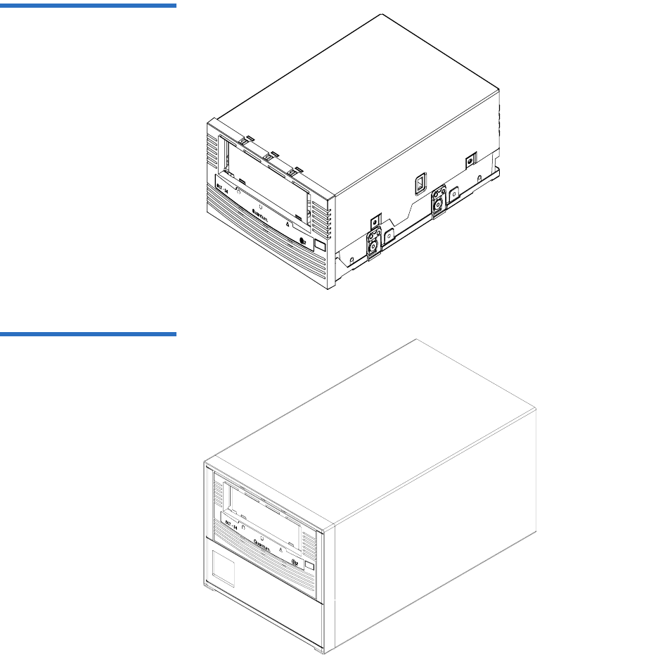
Tape Drive Models 1
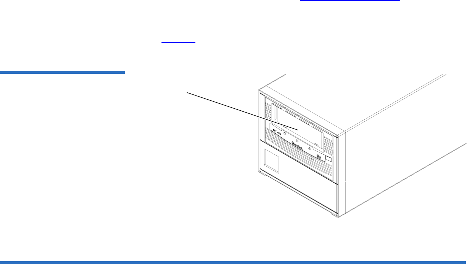
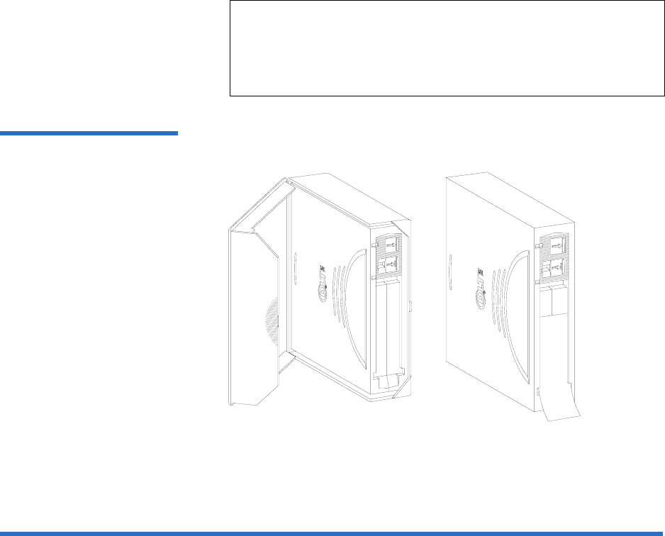
The tape drive system is available in three models: an internal unit for
server installation (see figure 1), a tabletop (or external) unit (see figure 2),
and a library model for installing in tape automation systems. The library
model (not shown) is similar to the internal model, but has a different
front bezel.
Mode Storage Capacity Transfer Rate
Native 800 Gigabytes (GB) 60 Megabytes per second
(MB/second)
Compresseda
a. 2:1 compression ratio.
1.6 Terabytes (TB) 120 MB/second
Chapter 1 Product Overview
Tape Drive Models
DLT-S4 Product Manual 3
Figure 1 Internal Tape Drive
Figure 2 Tabletop Tape Drive

Chapter 1 Product Overview
Tape Drive Features
DLT-S4 Product Manual 4
Tape Drive Features 1
The DLT-S4 tape drive system provides the following product features:
Feature Description
Media A streaming tape drive that uses half-inch wide
DLTtape S4 media
Form Factor A standard 5.25-inch full-height form factor to
simplify integration into system and tape library
solutions
Format
Compatibility Tape Drive Cartridge
DLT-S4 DLTtape S4
(write/read)
SDLT 600 Super DLTtape II
(read only)
SDLT 320 Super DLTtape I
(read only)
Interface
Options
Ultra320 SCSI
4 Gigabit (Gb) Fibre Channela
a. Fibre Channel and SAS interfaces are not available with the
tabletop model.
3 Gb SAS-1.1a
Capacity Mode Value
Native capacity 800 GB
Compressed capacity 1.6 TBb
(2:1 compression ratio)
b. In accordance with industry practice, a typical compression
ratio is quoted. Actual compression ratios depend on the
redundancy and kind of data files you write.

Chapter 1 Product Overview
Maximum Data Transfer Rate
DLT-S4 Product Manual 5
Maximum Data Transfer Rate 1
Table 1 shows the maximum and burst data transfer rates for the DLT-S4
tape drive.
Table 1 Maximum Transfer
Rate
Configuration Native Compressed Burst Maxa
a. The interface limits burst rates, not the design of the tape drive or the media.
2:1 >4:1
Ultra320 SCSI 60 MB/sec 120 MB/sec 140 MB/sec 320 MB/sec
Fibre Channel 60 MB/sec 125 MB/sec 180 MB/sec 4 Gb/sec
SAS-1.1 60 MB/sec 125 MB/sec 180 MB/sec 3 Gb/sec
Note: Cable lengths and cable type may limit attainable transfer rates.

Chapter 1 Product Overview
Functional Specifications
DLT-S4 Product Manual 6
Functional Specifications 1
This section provides performance data for the DLT-S4 tape drive.
Feature Value
Tape drive read/write transfer
ratea
a. Depending on data type, SCSI bus limitations, and the tape
system configuration.
Native—60 MB per second
Compressed—120 MB per
second
Tracks 80 logical tracks
1280 physical tracks
Track density 2988 tracks per inch (tpi)
Linear bit density 256 Kb per inch (Kbpi)
Read/Write media speed 155 inches per second (ips)
Rewind media speed 200 inches per second
Linear search media speed 200 inches per second
Average rewind timeb
b. Note that data is typical; times may be longer if error recovery
time is necessary.
70 seconds
Maximum rewind timeb140 seconds
Average access timeb
(from BOT)
70 seconds
Maximum access timeb
(from BOT)
142 seconds
Load to BOTb25 seconds
70 seconds (unformatted media)
Unload from BOTb25 seconds
Nominal media tension Stationary—3.0 ± 0.5 oz.
Operating speed—3.5 ± 0.5 oz.
Rewind—3.5 ± 0.5 oz.

Chapter 1 Product Overview
Tape Drive Technology
DLT-S4 Product Manual 7
Tape Drive Technology 1
The DLT-S4 tape drive incorporates state-of-the-art technologies that
contribute to the SDLT architecture. Some of these ideas are trademarked,
others are patented. Table 2 lists some of the important technologies that
comprise the DLT-S4 tape drive system.
Table 2 Tape Drive Technology
Technology Description
Laser Guided
Magnetic Recording
The DLT-S4 tape drive system is based on Quantum’s Laser Guided Magnetic
Recording (LGMR) technology. LGMR provides a unique combination of the
best optical and magnetic technologies, which results in dramatically higher
capacities by substantially increasing the number of recording tracks on the
data-bearing surface of the media.
Magneto Resistive
Cluster Heads
Magneto Resistive Cluster (MRC) heads are a densely packed array of small
Magneto Resistive (MR) tape heads precisely positioned using advanced thin-
film processing technology.
Advanced Partial
Response Maximum
Likelihood
Improving on Partial Response Maximum Likelihood (PRML) technology
traditionally used in disk drives and communication systems, Quantum’s
advanced PRML channel technology, co-developed with Lucent Technologies,
brings new levels of performance and capacity to high-performance linear tape
products.
Advanced Metal
Powder Media
Advanced Metal Powder (AMP) media is a state-of-the-art media using
durable metal powder technology for recording high densities of data. The
back side of AMP media receives a specially formulated coating to accept the
optical servo tracks, which ensures that the entire data-bearing side of the
media is available for recording data and eliminates the need for pre-
formatting.
Positive Engagement
Tape Leader
Buckling Mechanism
The positive engagement tape leader buckling mechanism engages the media
leader on cartridge load and disengages it on cartridge unload. It uses a metal
pin attached to the tape drive leader to link with molded clips permanently
attached to the media leader inside the cartridge.

Chapter 1 Product Overview
Tape Drive Components
DLT-S4 Product Manual 8
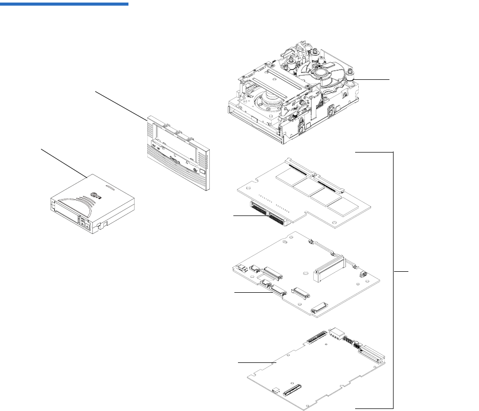
Tape Drive Components 1
The DLT-S4 tape drive is designed as a total system. The system includes
a complex interaction of a number of important components including
the base mechanical assembly, the front panel assembly (bezel), and the
board assemblies. Table 3 describes these components.
Table 3 Tape Drive Components
Components Description
Base mechanical
assembly
The base mechanical assembly houses the tape control mechanical, actuator,
reel motor, load mechanism, eject button, and front-panel indicators. It
positions the actuator servo head over the correct tape track. It implements the
functions required to buckle and unbuckle the media and control the media
motion. It engages the media leader on cartridge load and disengages it on
cartridge unload.
• Auto load—The tape auto load is a soft-load and seating mechanism that is
tolerant of forced media loading; a media sensor is triggered upon cartridge
insertion, and after the media reaches a hard stop point, the auto load sensor
engages, pulling the cartridges the remaining distance onto the motor. On
media ejection, the assembly reverses the process and automatically ejects
the cartridge a fixed distance from the front of the tape drive.
• Base plate—Acts as the support platform for the other modules and for the
tape drive enclosure. It also includes the mounting holes (shock mounts)
used to install the tape drive into a server or tape library.

Chapter 1 Product Overview
Tape Drive Components
DLT-S4 Product Manual 9
Front panel assembly
(bezel)
The front panel assembly (bezel) performs these functions:
• Protects the front of the drive from physical damage
• Channels air flow through the system
• Aligns the cartridge when it is inserted into the system
• Provides label identifiers for the LEDs mounted on the front of the tape
drive
• Enables cartridge ejection
• Reduces internal environmental contamination with a built-in dust door
(internal and tabletop configurations only)
Board assemblies The board assemblies provide the main control function for the system and the
interface from the system to the host computer, library, or autoloader. This
provides the Advanced Partial Response Maximum Likelihood (PRML) feature
of the Quantum DLT-S technology.
There are three board assemblies:
• Pre-amplifier Board (PAB) — The PAB contains the preamplfier for the read
heads, and the write driver for the write heads.
• Motor Driver Board (MDB) — The MDB interfaces with the reel motor
drivers and hall sensors, actuator driver and sensors, sensor and motor
drivers for the soft load, LEDs for front-panel indicators, and eject button
signals.
• Drive Control Board (DCB) — The DCB is the main control card for the
DLT-S4 tape drive. It sends commands to the MDB to control and drive the
tape mechanism. The board interfaces with the PAB to send signals to the
head for reading and writing.
Components Description
Chapter 1 Product Overview
Tape Drive Components
DLT-S4 Product Manual 10
Figure 3 Tape Drive Integrated
Components
Front panel
assembly (bezel)
Cartridge
Base
mechanical
assembly
Board
assemblies
MDB
DCB
PAB

Chapter 1 Product Overview
Interface Types
DLT-S4 Product Manual 11
Interface Types 1
This section contains the following information for the DLT-S4 tape drive:
•Host Interface
•Physical Characteristics
Host Interface 1The interface supported by an DLT-S4 tape drive is dependent on the
kind of Drive Control Board (DCB) PWA installed. The DLT-S4 tape
drive comes in these interface types:
• Tabletop model with Ultra320 SCSI interface
• Internal model with either an Ultra320 SCSI interface, 4 Gb Optical
Fibre Channel interface, or SAS Interface
Interface speeds and protocol options are shown in table 4.
Table 4 Interface Speed and
Options
Interface
Versions Speed (Maximum
Burst) Protocol Options
Ultra320
SCSI
320 MB/seconda
a. The SCSI bus itself limits this rate, not the design of the tape
drive or media.
Low Voltage Differential (LVD)
sense running up to 320 MB per
second burst
Ultra160 2/FAST-20/
Asynchronous
Fibre
Channel
1 Gb/second
2 Gb/second
4 Gb/second
Class3
Connect to N port, NL port,
FL port, and F port
SAS 1.5 Gb/second
3 Gb/second
Serial SCSI Protocol (SSP)

Chapter 1 Product Overview
Interface Types
DLT-S4 Product Manual 12
Physical Characteristics 1Table 5 lists the physical characteristics for each interface of the tape
drive. These interfaces are available from the rear panel (per type, per
port).
Table 5 Tape Drive Interface
Physical Characteristics Interface
Versions Physical Characteristics
Parallel SCSI Ultra320
LVD
SCSI ID/TERMPWR connector style: 6-pin
Connector style: 68-pin high density SCSI
Fibre
Channel
Topology-constrained (drive automatically detects
topology)
4 Gb interface (drive automatically detects speed)
LC connector with 850 nanometer SFP transceiver
(supplied)
SAS-1.1 Point-to-point topology
3 Gb interface (drive automatically detects speed)

DLT-S4 Product Manual 13
Chapter 2
2Before You Begin
Inappropriate or careless handling of DLT-S4 tape drive systems may
result in damage to the product. Follow the precautions and directions to
prevent damaging the DLT-S4 tape drive system. In addition, follow the
steps in Pre-Installation Guidelines on page 17 to ensure that you have the
correct hardware for the system configuration.
This chapter provides the following important information you need to
know before you install and use your DLT-S4 tape drive:
•Warranty Note provides a general reminder of certain precautions to
follow so you do not void your warranty
•Safety Precautions
•Tape Drive Handling and Storage Guidelines
•Electrostatic Discharge Protection
•Pre-Installation Guidelines describes proper steps to take before
installing the tape drive in a system

Chapter 2 Before You Begin
Warranty Note
DLT-S4 Product Manual 14
Warranty Note 2
See the tape drive warranty before installing the tape drive; the tape
drive’s warranty could be voided if the installation guidelines and
restrictions are not closely followed.
Generally, the Limited Product and Limited Repair Warranties are
contingent upon proper use in the application for which the product is
intended, and do not cover the product if you perform any of the
following actions:
• Modify the product without the manufacturer’s written approval
• Subject the product to unusual physical, environmental, or electrical
stress, including damage caused by handling or shipping in
unapproved containers or packaging
• Disturb any warranty labels, or the integrity of the product in any
other way
• Remove or damage the serial number label to the extent that
warranty status of the product cannot be determined
Safety Precautions 2
For your safety, follow all safety procedures described here and in other
sections of the document.
• Turn off the system into which the DLT-S4 tape drive is to be
installed or attached before installing or removing the tape drive to
prevent the possibility of electrical shock or damage to the tape drive.
• Unplug the system that contains—or is to contain—the tape drive
from AC power before installing the tape drive to provide an added
measure of safety.
• Read, understand, and observe all label warnings.

Chapter 2 Before You Begin
Tape Drive Handling and Storage Guidelines
DLT-S4 Product Manual 15
• The DLT-S4 tape drive uses a Class I laser product. This laser product
complies with 29 CFR 1200 and 29 CFR 1910 as applicable on the date
of manufacture.
Tape Drive Handling and Storage Guidelines 2
Damage to the DLT-S4 tape drive system can occur as the result of
careless handling, vibration, shock, or electrostatic discharge (ESD). For
more details on ESD, see Electrostatic Discharge Protection on page 16.
Follow these guidelines to avoid damage to the tape drive:
• Always handle the tape drive carefully and gently— a drop of ¼ inch
onto a bench or desktop can damage a tape drive.
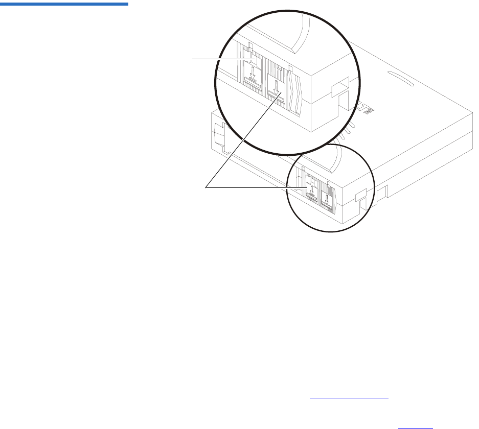
• Hold the internal tape drive only by its sides.
• Never hold or carry the tape drive by inserting your fingers into the
receiver area on the front of the tape drive. You could damage the
receiver area if you lift or carry it in this manner.
• Do not bump, jar, or drop the tape drive. Use care when transporting
the tape drive.
• Do not place the tape drive so that it rests on its front bezel.
• Always gently place the tape drive flat and horizontal on an
appropriate ESD-protected work surface to keep the tape drive from
accidentally being knocked over.
• Do not stack objects on the tape drive.
Warning: If you open the tape drive chassis, you may become
exposed to invisible laser emission which could be
harmful if you are directly exposed to the beam.
Caution: Never power off the tape drive or the host while the tape
drive contains a cartridge. Failure to remove a cartridge
may result in cartridge or tape drive damage.
Chapter 2 Before You Begin
Electrostatic Discharge Protection
DLT-S4 Product Manual 16
• Do not expose the tape drive to dusty, humid, or smoke-filled areas,
or to excessive heat or cold (see Physical Specifications on page 38 for
required temperature and humidity conditions).
• Do not place foreign objects inside the tape drive’s receiver area (see
figure 4).
Figure 4 Receiver Area
Electrostatic Discharge Protection 2
Several electrical components of the DLT-S4 tape drive system are
sensitive to static electricity and electrostatic discharge (ESD). Even a
static buildup or discharge that is too slight to feel can be sufficient to
destroy or degrade a component’s operation.
To minimize the possibility of ESD-related damage to the system, the
tape drive’s manufacturer strongly recommends using both a
workstation anti-static mat and an ESD wrist strap. If the devices are
correctly installed and properly used, they reduce the buildup of static
electricity that might harm the system.
Follow these guidelines to avoid ESD damage to the tape drive:
• Use a properly fitted wrist strap or other suitable ESD protection.
• Observe proper ESD grounding techniques.
• Keep the internal tape drive in its antistatic bag until ready to install.
Receiver area

Chapter 2 Before You Begin
Pre-Installation Guidelines
DLT-S4 Product Manual 17
• Place the tape drive in the antistatic bag before placing it in a
shipping container.
• Hold the internal tape drive only by its sides.
• Place the tape drive on a properly grounded anti-static work surface
pad while it is out of its protective antistatic bag.
• Do not pack other materials with the tape drive in its antistatic bag.
• Do not use the bag as a substitute for the work surface antistatic pad.
The outside surface of the bag may not have the same antistatic
properties as the inside surface. It could actually increase the
possibility of ESD problems.
• Do not remove either the tabletop tape drive cover or the internal/
library tape drive cover to use any test equipment to check
components on the PCBAs. There are no user-serviceable
components on the tape drive.
Pre-Installation Guidelines 2
Before you install the tape drive in a system, follow these steps. Also,
check the tape drive to be certain it is operating properly before installing
it in a system.
1Unpack and review the contents of the box for any physical damage.
If you find damaged items, contact the tape drive sales representative
and the shipping company immediately.
2Save the shipping box and packing materials in case you need to
move or ship the tape drive at a later date.
3Record the model and serial number of the DLT-S4 tape drive system
in the space provided below.
Caution: When returning a unit to Quantum for repair, you
must use the original or equivalent packing materials
or risk voiding your warranty.

Chapter 2 Before You Begin
Pre-Installation Guidelines
DLT-S4 Product Manual 18
These numbers provide specific information on the DLT-S4 tape
drive system and will be helpful if you must contact technical
support. You can find these numbers on the bottom of the tabletop
tape drive enclosure and on the top of the internal and library tape
drives.
4Check the enclosed SCSI, Fibre Channel, or SAS cable to ensure it is
compatible with the SCSI, Fibre Channel, or SAS controller card in
the host computer.
5Check the SCSI, Fibre Channel, or SAS interface on the host computer
to ensure that it is compatible with the tape drive (see table 5 on
page 12 for a list of the possible interfaces that are available and the
various options with each).
6Confirm that your back-up software and operating system are
compatible with the tape drive.
See www.quantum.com for the most up-to-date compatibility
information.
Model Number
(usually begins with TC)
Serial Number
(usually begins with QP, QX,
or QK)

DLT-S4 Product Manual 19
Chapter 3
3Cartridges
This chapter discusses the cartridges that you can use in the DLT-S4 tape
drive. This chapter covers the following topics:
•Choosing Compatible Cartridges
•Using Unsupported Cartridges
•Backward-read Compatibility Transfer Rate
•Cartridge Handling and Storage Guidelines
•Inspecting a Cartridge
•Write-protecting a Cartridge
•Loading a Cartridge
•Unloading a Cartridge
•DLTSage WORM [explains how create a secure archival write-once,
read-many (WORM) cartridge]
Choosing Compatible Cartridges 3
The only cartridge the DLT-S4 tape drive can both read and write to is the
DLTtape S4 cartridge.
Chapter 3 Cartridges
Choosing Compatible Cartridges
DLT-S4 Product Manual 20
The DLT-S4 tape drive can read from, but not write to:
• Super DLTtape II cartridges formatted in the SDLT 600 tape drive
• Super DLTtape I cartridges formatted in the SDLT 320 tape drive
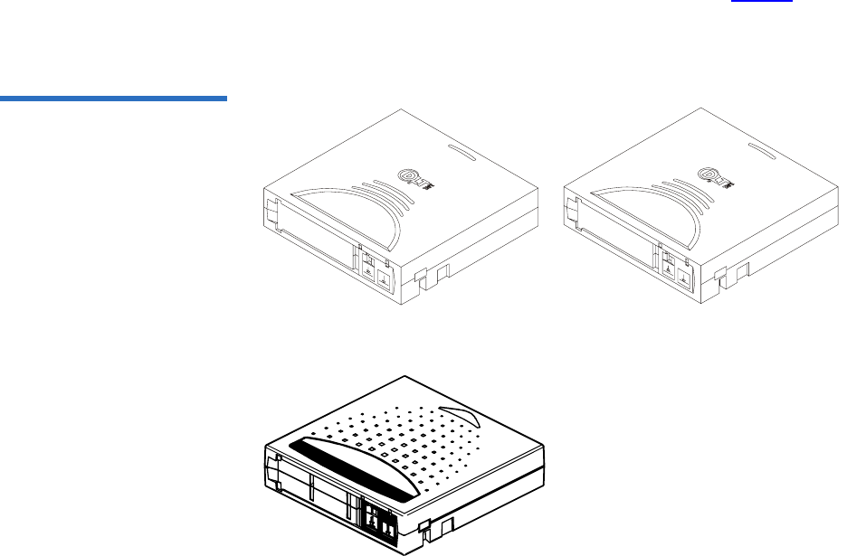
The DLTtape S4 cartridge is black and has a distinctive pattern molded
into the plastic, along with the DLTtape logo. The cartridge is made of
wear-resistant materials to reduce the potential for debris generation and
increase the life of the cartridge.
The cartridge’s geometry is similar to previous DLTtape cartridges to
simplify integration with existing tape library designs (see figure 5). Its
keying feature, however, ensures that it cannot be loaded into previous
generation tape drives.
Figure 5 Compatible Tape
Cartridges
DLTtape S4 Data Cartridge (BLACK) Super DLTtape II Data Cartridge (BLUE)
Super DLTtape I Data Cartridge (GREEN)

Chapter 3 Cartridges
Using Unsupported Cartridges
DLT-S4 Product Manual 21
Using Unsupported Cartridges 3
DLT-S4 tape drives are intended to be used only with the cartridges
specified in Choosing Compatible Cartridges on page 19. However,
Quantum DLT drives are tested with a variety of unsupported cartridges
and are designed to ensure that no damage occurs to either the tape drive
or the cartridge if a user attempts to use an unsupported cartridge.
If you try to insert an unsupported cartridge into the DLT-S4 drive, the
drive will not be able to accept it. Possible results are:
• You may not be able to insert the unsupported cartridge into the
drive.
• The unsupported cartridge may trigger the soft-load mechanism at
an inappropriate time, which may cause the soft-load mechanism to
stop at an improper location. While the soft-load mechanism is
stopped, the unsupported cartridge may not be completely loaded in
the drive, and the drive may not automatically eject the cartridge. (If
this happens, you must manually eject the cartridge by issuing an
EJECT command or by pressing the Eject button.)
• If the unsupported cartridge does manage to load properly, the drive
will not be able to buckle, read, or write to it. If this happens, a load
failure will be issued over the interface. (If this happens, you must
manually eject the cartridge by issuing an EJECT command or by
pressing the Eject button.)
When a compatible cartridge is loaded correctly, the left LED lights either
green or orange. If you load, or attempt to load, an incompatible
cartridge, the left LED stays off (see Loading a Cartridge on page 32).

Chapter 3 Cartridges
Backward-read Compatibility Transfer Rate
DLT-S4 Product Manual 22
Backward-read Compatibility Transfer Rate 3
The DLT-S4 tape drive includes a backward-read compatibility feature
that enables it to read Super DLTtape I and Super DLTtape II cartridges
(but not write to these cartridges). The following table lists the transfer
rates for backward-read cartridges.
Table 21 Backward-read
Compatibility Transfer Rates
Formata
a. Tape drives older than the DLT-S4 will eject a data cartridge written with DLT-S4 format.
Cartridge Type Native Capacity Native Read
Transfer Rate
Native Read
Transfer Rate in
DLT-S4 Tape
Driveb
b. Transfer rates shown are the minimum when reading uncompressed data.
SDLT 600 Super DLTtape II 300 GB 36.0 MB/sec ≥ 18.0 MB/sec
SDLT 320 Super DLTtape I 160 GB 16.0 MB/sec ≥ 8.0 MB/sec

Chapter 3 Cartridges
Cartridge Handling and Storage Guidelines
DLT-S4 Product Manual 23
Cartridge Handling and Storage Guidelines 3
DLTtape S4 cartridges are engineered to be reliable, robust, and durable.
They are manufactured to withstand 1,000,000 head passes and have a
shelf life of 30 years. By following these guidelines, you will greatly
reduce the chance that you will experience problems with the cartridges
or cause damage to the tape drive system.
For best results, follow these guidelines for data cartridge handling and
storage:
• Follow the handling instructions and observe the environmental
specifications provided in the plastic cartridge case.
• Inspect tape cartridges for damage as described in Inspecting a
Cartridge on page 25.
• Store cartridges vertically in their protective cases when not in use or
when archived (see figure 6).
• Protect cartridges from shock, vibration, moisture, direct sunlight,
dust, smoke, and magnetic fields.
• Do not stack more than five cartridges on top of each other.
• Do not carry cartridges loosely in a box or any other container.
Allowing cartridges to jostle together exposes them to unnecessary
physical shock.
• When carrying cartridges in their cases, orient the cases so that the
grooves in the cases interlock. This prevents the cases from slipping
apart and falling.
• Do not drop the cartridge. A dropped cartridge may have dislodged,
loosened, or damaged internal components. If you drop a cartridge,
give it a thorough visual inspection (see Inspecting a Cartridge on
page 25 for complete instructions).
Caution: The safety of data depends on proper care and handling of
cartridges.
Caution: Never power off the tape drive while it contains a
cartridge. Failure to remove a cartridge prior to power-off
may result in cartridge or tape drive damage.

Chapter 3 Cartridges
Cartridge Handling and Storage Guidelines
DLT-S4 Product Manual 24
• Use only the slide-in labels provided with each cartridge or slide-in
bar code labels designed for use with DLT media. Slide labels into the
label slot on the cartridge (see figure 6). Never apply adhesive labels
or “sticky” notes on the top, side, or bottom of tape cartridges, and do
not write on the cartridge.
• Do not write on the labels with debris-producing writing
instruments, such as graphite pencils and water-soluble felt pens.
• Other than the bar code label, ensure that nothing else is stuck to the
cartridge before inserting it into the tape drive. Loose labels and other
materials can cling to the bottom of the cartridge and get stuck in the
tape drive.
• Leave unused labels attached to the printed material (called the
u-card) within the cartridge case.
• Store any loose labels or other materials that are smaller than 4.5 x 4.5
inches (114.3 x 114.3 mm) separate from the cartridge. A loose label or
piece of paper accidentally inserted into the tape drive along with a
cartridge can prevent the hub reel and tape drive gear from meshing.
• Never touch the tape or media leader. Dust and oils from your skin
contaminate the tape and affect performance.
• Avoid unnecessarily opening the cartridge media access door (see
figure 9). This may expose the media to contamination or physical
damage.
• Protect cartridges from shock, vibration, moisture, direct sunlight,
dust, smoke, and magnetic fields. Devices that may produce
magnetic fields, such as computer monitors, motors, or video
equipment can alter or erase data on the media.
• Observe the proper temperature and humidity conditions for
operating and storing cartridges as follows:
Temperature
Operating 10 °C to 40 °C (50 °F to 104 °F)
Storage (with data) 18 °C to 28°C (64 °F to 82 °F)
Humidity
Operating 20% to 80% non-condensing
Storage (with data) 40% to 60% non-condensing
Chapter 3 Cartridges
Inspecting a Cartridge
DLT-S4 Product Manual 25
Figure 6 Data Cartridge Care
Inspecting a Cartridge 3
Improper cartridge handling is the primary reason for tape drive
problems. To avoid losing data or damaging the tape drive, inspect the
cartridges:
• Before loading a new cartridge in the tape drive
• After dropping a cartridge or subjecting it to physical shock
Note: If storage or transportation of a cartridge has exposed it to
temperature or humidity conditions outside the
specifications shown in the preceding table, allow the
cartridge to acclimate to the proper operating environment
for 24 hours before using it.
Use slide-in labels
Store data cartridges vertically in
plastic cases
Chapter 3 Cartridges
Inspecting a Cartridge
DLT-S4 Product Manual 26
• When the tape drive becomes inoperable after loading a cartridge
• When you receive a shipment of cartridges that show any sign of
shipping damage
Follow these steps to inspect a tape cartridge:
1Gently shake the cartridge and listen for loose pieces.
2Remove the cartridge from its protective plastic case.
3Check for loose debris attached to the cartridge, and for other
contamination (oily, slimy, or sticky substances) that may have built
up on the surface of the cartridge.
4Check the cartridge for any obvious cracks or other physical damage.
Rotate the cartridge in your hands, looking for broken or missing
parts.
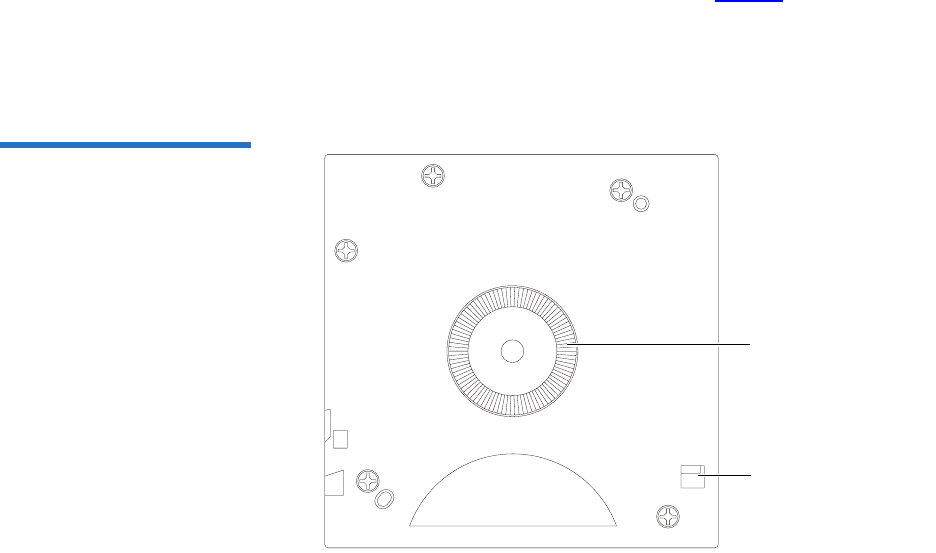
5Rotate the cartridge to view the bottom (see figure 7).
Confirm that the spring-loaded hub on the bottom of the cartridge is
centered. Press the hub to ensure that the spring is functioning
properly and that the hub returns to its normal position.
Figure 7 Cartridge Bottom
View
Spring-loaded hub
Reel lock
Chapter 3 Cartridges
Inspecting a Cartridge
DLT-S4 Product Manual 27
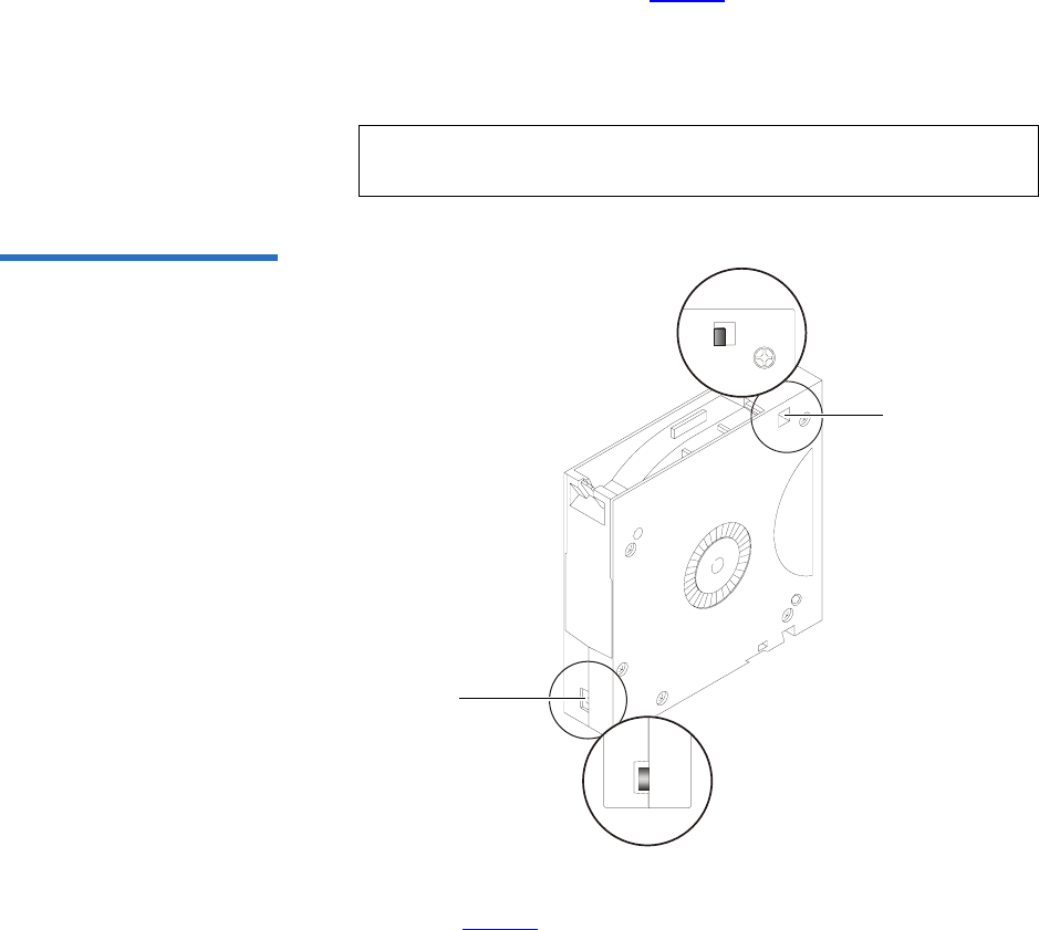
6Check that both reel lock tabs (the small plastic tabs inside the reel
lock) are partially visible (see figure 8).
One reel lock is located on the end of the cartridge that is inserted
into the tape drive. The other is on the bottom of the cartridge. The
reel locks are black.
Figure 8 Cartridge Reel Locks
7Open the media access door by pressing on the tab in the door pivot
notch (see figure 9). Ensure that you do not touch the media leader.
Note: The reel locks can break if you drop the cartridge. If the
reel lock tabs are not visible, do not use the cartridge.
Reel lock
Reel lock
Chapter 3 Cartridges
Inspecting a Cartridge
DLT-S4 Product Manual 28
Figure 9 Opening the Media
Access Door
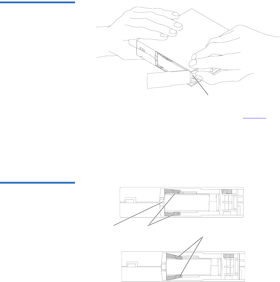
8Compare what you see inside the media access door to figure 10.
Look for damage to the cartridge buckling clips, including:
• Bent or “toed-in” appearance on one or both clips
• Improper seating (clips should be fully retracted towards the left
side of the opening)
• Bending of the leader bar that supports the clips
Figure 10 Inspecting Inside the
Media Access Door
Tab in the door pivot notch
Proper position
of cartridge
buckling clips Cartridge buckling clips
excessively “toed-in”
Leader bar

Chapter 3 Cartridges
Write-protecting a Cartridge
DLT-S4 Product Manual 29
9Examine the visible media leader (without touching it) for excessive
debris, oily or sticky residue, condensed droplets of moisture, or any
other signs of contamination.
10 Finally, check for proper operation of the cartridge’s write-protect tab
(see figure 11).
This sliding tab, located on the end of the cartridge used for the label,
should snap smartly back and forth, and the orange tab should be
visible when the cartridge is set to provide write protection (you
cannot write over the data already on the media).
Write-protecting a Cartridge 3
Each cartridge has a write-protect tab, which you can use to prevent
accidental erasure of data. Before inserting the cartridge into the tape
drive, position the write-protect tab on the front of the cartridge (see
figure 11) according to the kind of operations you expect to perform.
Caution: If a cartridge shows any signs of damage, do not use it.
If a cartridge is dropped, retrieve the data, back it up
on a new cartridge, and dispose of the dropped
cartridge. A dropped cartridge should not reused even
if it shows no signs of damage.
Note: To ensure you don’t erase valuable data already written to a
data cartridge, always make sure the cartridge is write-
protected before inserting it into the tape drive.
Chapter 3 Cartridges
Write-protecting a Cartridge
DLT-S4 Product Manual 30
Figure 11 Cartridge Write-
protect Tab
•To enable write protection — Slide the write-protect tab to the left so
that the bright orange rectangle is visible. This is the visual reminder
that you cannot write data to the media.
You can read existing data; however, you cannot write over existing
data on the media, nor append additional data to the media.
•To disable write protection — Slide the write-protect tab to the right so
that the orange rectangle is not visible.
You can write over existing data on the media, and you can append
additional data to the media unless the cartridge is write-protected
via firmware (in other words, the cartridge has been formatted as a
DLTSage WORM cartridge; see DLTSage WORM on page 34 for
details).
For more details about write-protecting a cartridge, see table 22.
Orange
indicator
rectangle
Write-
protect tab

Chapter 3 Cartridges
Write-protecting a Cartridge
DLT-S4 Product Manual 31
Table 22 Write-protect Tab
Positions Write-protect
Tab Position Orange Write-
protect
Indicator
Result
Before Loading the Cartridge
Enabled
(Slide tab to left)
Visible • You cannot write data to the
media
• You cannot overwrite existing
data on the media
• You cannot append
additional data to the media
Disabled
(Slide tab to
right)
Not Visible Unless the cartridge is write-
protected via firmware:
• You can write data to the
media
• You can overwrite existing
data on the media
• You can append additional
data to the media
After Loading the Cartridge and During Operation
If you move the
write-protect tab
from its right
(disabled)
position to its left
(enabled)
position
Visible If the tape drive is currently
writing to a cartridge, the write-
protect feature does not take
effect until after the current write
operation completes.
If you move the
write-protect tab
from its left
(enabled)
position to its
right (disabled)
position
Not Visible The cartridge becomes write-
enabled after a variable number
of seconds.

Chapter 3 Cartridges
Loading a Cartridge
DLT-S4 Product Manual 32
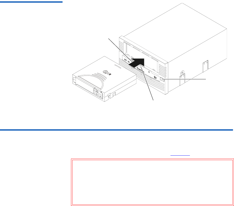
Loading a Cartridge 3
Follow these steps to load a cartridge (see figure 12).
1Insert the cartridge into the receiver on the front of the tape drive.
2Push the front center of the cartridge into the tape drive until the soft-
load mechanism engages and mounts the tape.
The middle LED flashes to show that the media is loading. When the
media reaches the Beginning of Tape (BOT) marker, the middle LED
lights steadily.
The cartridge is now ready for use.
To verify that you have loaded a compatible cartridge, look at the left
LED for the following indications.
For more information on choosing cartridges, see Choosing Compatible
Cartridges on page 19.
If the Left LED is... Then this cartridge is loaded...
Green DLTtape S4
Orange Super DLTtape I or Super DLTtape II
Off No cartridge is inserted or an incompatible
cartridge is inserted
Chapter 3 Cartridges
Unloading a Cartridge
DLT-S4 Product Manual 33
Figure 12 Loading a Cartridge
Unloading a Cartridge 3
Follow these steps to unload a cartridge (see figure 12).
1Press the Eject button (or issue an appropriate system software
command).
The tape drive completes any active writing, then rewinds. The
middle LED flashes as the media rewinds. When the media is
finished rewinding, the tape drive ejects the cartridge and the middle
LED lights steadily.
Caution: Never turn off the tape drive or the host while the tape
drive contains a cartridge. Failure to remove a cartridge
prior to power-off may result in cartridge or tape drive
damage.
Do NOT rush removal of the cartridge. Wait until the tape
drive ejects the cartridge and the middle LED lights steady
before removing the cartridge.
Eject button
Middle LED
Left LED

Chapter 3 Cartridges
DLTSage WORM
DLT-S4 Product Manual 34
2Remove the cartridge from the tape drive and return it to its plastic
case to protect it from damage.
DLTSage WORM 3
DLTSage WORM is the firmware compliance management function of
DLTSage. This feature uses a Write Once, Read Many (WORM)
functionality, which allows you to securely archive data stored on a
DLTtape S4 cartridge written on a DLT-S4 tape drive. The firmware
allows you to append data to a cartridge, but you cannot rewrite,
reformat, or erase the data.
DLTSage WORM firmware is a standard feature of the DLT-S4 tape drive
and the DLTtape S4 cartridge. See Formatting a Cartridge as DLTSage
WORM on page 35 for instructions on how to create a WORM cartridge.
DLTSage WORM Features 3This section details the many features of DLTSage WORM. For more
information, see
http://www.dlttape.com/technology/DLTSageWORM/index.aspx
Feature Description
Security The tape drive’s firmware places an electronic signature key on each cartridge to
ensure that data written to the media cannot be rewritten, reformatted, or erased.
• The key is a unique identifier that cannot be altered.
• The firmware allows you to append new data to the cartridge.
• The cartridge initialization process assures that only unformatted cartridges will
be WORM enabled.
Verification The verification is a two-part process.
• The DLT-S4 tape drive provides best-of-class verification through its ECC
algorithms.
• The firmware provides archive media verification and tamper verification with
time and date signatures.

Chapter 3 Cartridges
DLTSage WORM
DLT-S4 Product Manual 35
Formatting a Cartridge as
DLTSage WORM 3Some backup software applications work with DLTSage to allow you to
format a tape cartridge as DLTSage WORM directly via the backup
software user interface.
If your backup software application does not allow this, you can use
xTalk Management Console to create the DLTSage WORM cartridge. (See
xTalk Management Console on page 135 for information about xTalk
Management Console.)
Follow these steps to format a cartridge with DLTSage WORM using
xTalk Management Console:
1If xTalk Mangement Console is not installed on your computer,
download it now (see Accessing the Tools on page 132 for
instructions on downloading).
2Obtain a blank DLTtape S4 cartridge that you want to format as
DLTSage WORM. Ensure that the cartridge contains no data.
3Insert the cartridge into the drive and wait for the tape drive to come
ready.
4Launch xTalk Management Console.
5Click the DLTSage WORM button on the toolbar (see figure 13).
Identification The identification applies to both the data and the cartridges.
• The storage management software issues a time and date stamp, which enables
you to locate and authenticate specific records using ISV compliant storage
management software.
• The cartridge used for DLTSage WORM is a standard DLTtape S4 cartridge. Use
the special yellow labels provided by Quantum to identify the WORM
cartridges.
Duplication The data stored on the DLTtape S4 cartridge can be downloaded to another storage
media through any ISV-compliant storage management software.
Feature Description

Chapter 3 Cartridges
DLTSage WORM
DLT-S4 Product Manual 36
Figure 13 DLTSage WORM
Button
The DLTSage WORM Wizard displays.
6Click Format to continue.
The cartridge is formatted as a DLTSage WORM cartridge.
Further information and instructions are available in the xTalk
Management Console for Windows User’s Guide found in the Help menu in
xTalk Management Console.

DLT-S4 Product Manual 37
Chapter 4
4Specifications
This chapter provides the following specifications for the DLT-S4 tape
drive:
•Physical Specifications
•Dimensions and Weights
•Electromagnetic Field Specifications
•Acoustic Noise Emissions
The specifications noted are applicable to the drive itself and not as it is
integrated into an automation system. Testing performed to validate
these specifications was done with the internal tape drive and the
tabletop tape drive models.

Chapter 4 Specifications
Physical Specifications
DLT-S4 Product Manual 38
Physical Specifications 4
Table 23 lists error types and environmental operating and storage limits
for the DLT-S4 tape drive.
Table 23 Physical Specifications
Data Integrity
Error Type Frequency
Detected, Unrecoverable Read < 1 error in 1018 bits read
Undetected Read < 1 error in 1027 bits read
Temperature
Operating 10 °C to 40 °C (50 °F to 104 °F)
Storage -40 °C to 66 °C (-40 °F to 150 °F)
Humidity
Operating 20% to 80% non-condensing
Storage 10% to 95% non-condensing
Safety Certifications
Meets UL 60950, GS mark, and EN60950/IEC 950 standards (EN60825-1: Information Technology
Equipment). See the DLT-S4 Product Specification for more detailed information.
Air Flow
10.4 CFM minimum with 0.09 in H2O pressure drop
Note: Allow at least 100 mm of unobstructed space behind the tape drive for proper air flow.
Electrical Rating (numbers describe the SCSI model)
Tabletop 85 to 264 VAC, 63 W typical,
100 W (power supply rating) maximum, 47 to 63 Hz
Internal +5 V, 4.9 A RMS, 6.2 A Peak, typical
+12 V, 0.7 A RMS, 2.7 A Peak, typical

Chapter 4 Specifications
Dimensions and Weights
DLT-S4 Product Manual 39
Dimensions and Weights 4
Table 24 lists the dimensions and weights for the internal, library, and
tabletop tape drives.
Table 24 Tape Drive Physical
Dimensions
Table 25 Unpackaged and
Shipping Weights
Dimension Internal Model Library Model Tabletop Model
Height (without the front
bezel)
(including the front bezel)
82.55 mm (3.25 in.)
85.73 mm (3.38 in.)
82.55 mm (3.25 in.)
85.73 mm (3.38 in.)
164.46 mm (6.48 in.)
Width (without the front
bezel)
(including the front bezel)
146.05 ± 1.143 mm
(5.75 ± .045 in.)
148.59 mm (5.85 in.)
146.05 ± 1.143 mm
(5.75 ± .045 in.)
148.59 mm (5.85 in.)
174.75 mm (6.88 in.)
Depth (from the rear of the
front bezel)
(including the front bezel)
203.20 mm (8.00 in.)
212.73 mm (8.375 in.)
204.47 mm (8.05 in.)
213.61 mm (8.41 in.)
320.04 mm (12.60 in.)
Note: The mounting hole pattern for the bottom and sides of the system is industry standard.
Weight Internal Version Tabletop Version
Unpackaged weighta
a. Weights depend on the configuration.
2.38 kg (5.25 lbs.) 6.27 kg (13.82 lbs.)
Shipping weightb
b. The packaging used may change the shipping weight
3.77 kg (8.31 lbs.) 9.90 kg (21.83 lbs.)

Chapter 4 Specifications
Electromagnetic Field Specifications
DLT-S4 Product Manual 40
Electromagnetic Field Specifications 4
Quantum tape drives are electrical devices; as such, this equipment
generates, uses, and may emit radio frequency energy. The tape drives
may emit energy in other frequencies, as well, as discussed in the
following sections.
Electromagnetic
Emissions 4The internal tape drive model complies with Class A limits in a
2U Rackmount enclosure. The tabletop tape drive model complies with
Class B limits. The library tape drive model is subject to the enclosure
utilized in an automation system integration.
Table 26 lists electromagnetic interference (EMI) regulations and
certifications held by the DLT-S4 tape drive internal and tabletop models.
Table 26 EMI Regulations and
Certifications
Type Regulation/Certification
EEC Directive 89/336 CE BS6527 (UK)
EN55022 (EU)
EN55024 (EU)
CFR 47, 1995 FCC Rules Part 15 (MDOC)
IECS-003 Canada
V-3/97.04 VCCI (Japan)
CNS 13438 BSMI (Taiwan)
AS/NZS 3548 C-tick (Australia/New Zealand)

Chapter 4 Specifications
Electromagnetic Field Specifications
DLT-S4 Product Manual 41
Electromagnetic
Interference and
Immunity 4
The DLT-S4 tape drive internal and tabletop models were tested to the
performance limits listed in Table 27 (per legislative and customer
requirements). The drives were tested to the latest standards in effect on
the date of the test, and passed in all cases.
Table 27 Electromagnetic
Interference and Immunity Test
Summary
Test Name Test Specification Required
Performance
EN55022: 2003 Radiated and Conducted Emissions
Radiated Electromagnetic Emissions
EN55022: 2003 Class B
Conducted Electromagnetic Emissions
Current Harmonics and Flicker Emissions Tests
AC Power Supply Harmonic Emissions EN61000-3-2 Pass
AC Power Supply Voltage Flicker EN61000-3-3 Pass
EN55024: 1998 Immunity Tests
Electrostatic Discharge Immunity EN61000-4-2 Criteria Aa
a. The minimum legal requirement for this drive is Criteria B; however, the drive was tested to
and passed Criteria A.
Radiated Electromagnetic Immunity EN61000-4-3 Criteria A
Electrical Fast Transient / Burst Immunity EN61000-4-4 Criteria B
Electrical Surge Immunity EN61000-4-5 Criteria B
Conducted Electromagnetic Immunity EN61000-4-6 Criteria A
Power Frequency Magnetic Field Immunity EN61000-4-8 Criteria A
AC Voltage Dips and Interrupts Immunity EN61000-4-11 Criteria B

Chapter 4 Specifications
Acoustic Noise Emissions
DLT-S4 Product Manual 42
Acoustic Noise Emissions 4
This section lists acoustic noise emission levels, both as noise power and
sound pressure. The table provides the preliminary declared values per
ISO 9296 and ISO 7779/EN27779. The values shown in table 28 are the
maximum values based on 3 sigma limits from a distribution of tape
drives.
Table 28 Acoustic Noise
Emissions
Mode Internal Tabletop
Noise Power Emission Level (LNPEc)
Idle Not applicable 5.4 Bel
Streaming 5.9 Bel 5.9 Bel
Sound Pressure Level (LPAc)a
a. Sound pressure level measured at front of tape drive.
Idle Not applicable 42 dB
Streaming 47 dB 53 dB

DLT-S4 Product Manual 43
Chapter 5
5Common Interface
Information
This chapter provides interface specifications that apply to all variations
of the DLT-S4 tape drive, which include the following topics:
•SCSI Command Timeout lists the length of time the SCSI command
initiator waits for a response before it times out for each SCSI
command
•Rear Panel Connectors describes how to use the connectors on the
rear of the tape drive, defines the connectors, and lists the power and
loader connector pinouts

Chapter 5 Common Interface Information
SCSI Command Timeout
DLT-S4 Product Manual 44
SCSI Command Timeout 5
This section lists the length of time the SCSI command initiator waits for a
response before it times out.
Table 29 SCSI Command
Timeout Values
Command Timeout
ERASE 6 hours (overwrite
entire media)
INQUIRY 500 milliseconds
LOAD/UNLOAD 16 minutes
LOCATE 6 hours
LOG SELECT 500 milliseconds
LOG SENSE 500 milliseconds
MODE SELECT 500 milliseconds
MODE SENSE 500 milliseconds
PERSISTENT RESERVE IN 500 milliseconds
PERSISTENT RESERVE OUT 500 milliseconds
PREVENT/ALLOW MEDIA REMOVAL 500 milliseconds
READ 1 hour
READ ATTRIBUTE 500 milliseconds
READ BLOCK LIMITS 500 milliseconds
READ BUFFER 3 minutes
READ POSITION 500 milliseconds
RECEIVE DIAGNOSTIC RESULTS 500 milliseconds
RELEASE (10) 500 milliseconds
RELEASE UNIT 500 milliseconds

Chapter 5 Common Interface Information
SCSI Command Timeout
DLT-S4 Product Manual 45
REPORT DENSITY SUPPORT 500 milliseconds
REPORT DEVICE IDENTIFIER 500 milliseconds
REPORT LUNS 500 milliseconds
REPORT SUPPORTED OPERATION CODES 500 milliseconds
REQUEST SENSE 500 milliseconds
RESERVE (10) 500 milliseconds
RESERVE UNIT 500 milliseconds
REWIND 6 minutes
SEND DIAGNOSTIC 20 minutes
SET DEVICE IDENTIFIER 500 milliseconds
SPACE 6 hours (directory
may need rebuilding)
TEST UNIT READY 500 milliseconds
VERIFY 1 hour
WRITE 1 hour
WRITE ATTRIBUTE 500 milliseconds
WRITE BUFFER (UPDATE FIRMWARE) 10 minutes
WRITE FILEMARKS 1 hour
Note: For more information on SCSI commands, see the DLT-S4
Interface Reference Guide (81-81281-xx).
Command Timeout

Chapter 5 Common Interface Information
Rear Panel Connectors
DLT-S4 Product Manual 46
Rear Panel Connectors 5
This section describes how to use the rear panel connectors that are
common to all models of the tape drive.
For the locations of these connectors, see the following illustrations:
•SCSI— Figure 15 on page 49
• Fibre Channel— Figure 17 on page 56
•SAS — Figure 20 on page 63
Power Connector Pin
Assignments 5Pin assignments for the 4-pin power connector are listed here. Pin 1 is
indicated by a solid red dot in the illustrations.
Loader/Library Interface
Connector 5The connector for the library/tape drive interface is an RS-422 serial port
set to 9600 baud, 8 bits per character, no parity, and 1 stop bit. All data
sent to or from the library/tape drive interface consists of bit-wise
encoded hex values.
This 10-pin loader connector provides the signals used when the tape
drive is part of a loader/library configuration. The loader connector
provides a “universal port” that can support various serial interface
protocols. The electrical signals from the DLT-S4 tape drive need to be
translated to the appropriate serial interface protocol by a hardware and
software interface system.
The Loader/Library Controller interface conforms to the T10 Committee
Automation/Drive – Transport Protocol (ADT) Specification (see www.t10.org).
Pin Number Signal Name
1 +12 V DC
2 Ground (+12 V return)
3 Ground (+5 V return)
4+5 V DC
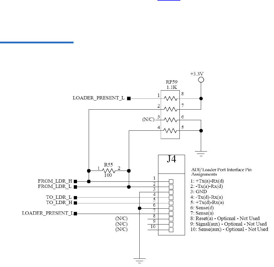
Chapter 5 Common Interface Information
Rear Panel Connectors
DLT-S4 Product Manual 47
The loader connector part number is Molex, 89401-1010; it is a single row,
10x2 mm configuration. See figure 14 for a schematic representation of
the connector and for connector pin assignments.
For more information, see the DLT Tape Drive Library Interface Specification
(6464162-xx).
Figure 14 ADI/Loader Port
Interface Schematic

DLT-S4 Product Manual 48
Chapter 6
6Parallel SCSI Interface
This chapter provides SCSI interface specifications associated with the
DLT-S4 tape drive, which includes the following topics:
•Rear Panel Connectors
•SCSI Cable Connectors
•SCSI Tape Drive Features
•SCSI Stub and Cable Lengths
•SCSI Connectors and Pin Assignments
For information on transfer rates and protocol options, see table 4 on
page 11.
For more information on the SCSI interface, see the DLT-S4 Interface
Reference Guide (81-81281-xx).
Also, see the latest SCSI reference documentation available at www.t10.org.
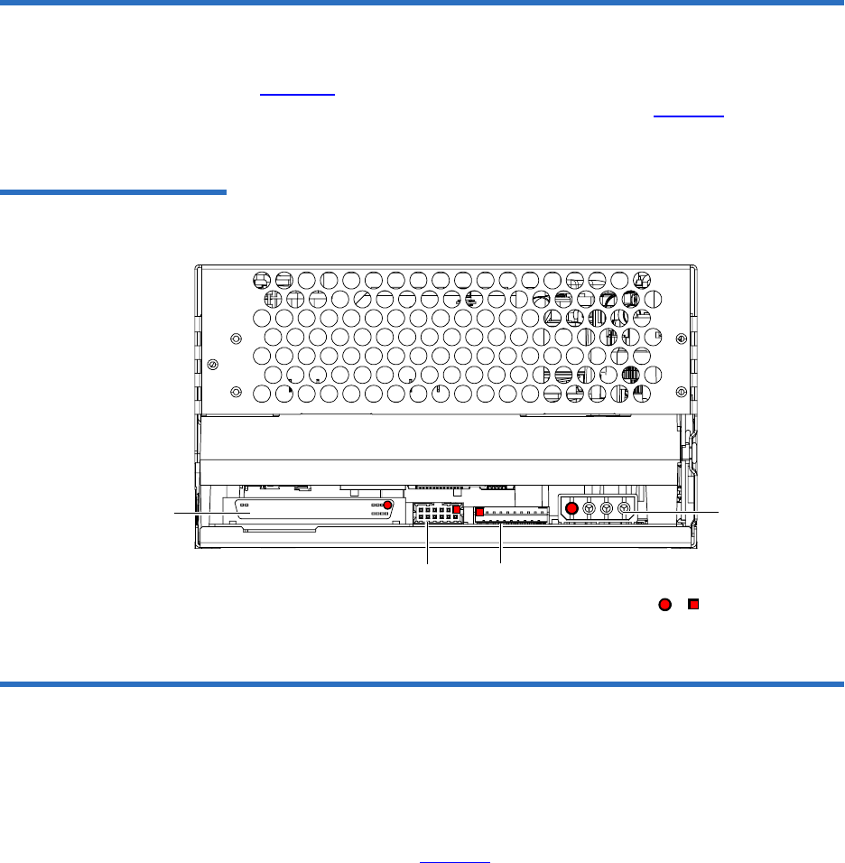
Chapter 6 Parallel SCSI Interface
Rear Panel Connectors
DLT-S4 Product Manual 49
Rear Panel Connectors 6
Figure 15 shows the location of the connectors on the rear panel of the
DLT-S4 SCSI configured internal tape drive. (See figure 38 on page 100
for an illustration of the SCSI connectors on the tabletop model.)
Figure 15 SCSI Connectors
and Jumpers (Rear View)
SCSI Cable Connectors 6
SCSI models of the DLT-S4 tape drive have two high-density 68-pin SCSI
connectors. Connect the tape drive to the computer using a SCSI cable
with the correct type of connector on each end. The tape drive operates
best when the computer and host end of the cable have one of the types of
connector shown in figure 16. (The tape drive will, however, operate with
other host-end connectors.)
Loader/library
interface connector
(10 pin)
SCSI ID jumper
block (includes
TERMPWR Enable) or denotes pin #1
Power
connector
(4 pin)
SCSI connector
(68 pin)
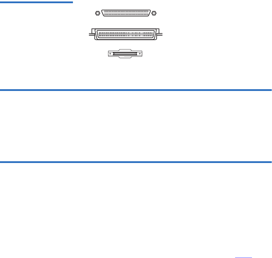
Chapter 6 Parallel SCSI Interface
SCSI Tape Drive Features
DLT-S4 Product Manual 50
Figure 16 SCSI Connectors
SCSI Tape Drive Features 6
The DLT-S4 tape drive conforms to the Ultra320 SCSI standard and
allows for a maximum burst rate of 320 MB per second.
Quantum recommends one DLT-S4 tape drive per bus, with a maximum
of two DLT-S4 tape drives per bus.
SCSI Stub and Cable Lengths 6
The longest stub length on the DLT-S4 PCBA is 1.64 inches, and the
maximum cable length for one DLT-S4 tape drive is 20 meters. The
maximum SCSI cable interconnect length is 10 meters total with a
maximum of two DLT-S4 tape drives on the bus.
To operate properly in Ultra320 mode, ensure that all SCSI cables and
terminators are Ultra320 (SPI-4) compatible.
For more information on the SCSI interface, see the DLT-S4 Interface
Reference Guide (81-81281-xx).
For information on transfer rates and protocol options, see table 4 on
page 11.
High-density 68-pin Micro DB68 or
Mini DB68
SCA 80-pin Hot Swap Connector
Very High-density Interconnect
Connector

Chapter 6 Parallel SCSI Interface
SCSI Connectors and Pin Assignments
DLT-S4 Product Manual 51
SCSI Connectors and Pin Assignments 6
This section shows the connector pin assignments for:
• MSE Mode SCSI connector (see table 30)
• MSE LVD Mode SCSI connector (see table 31)
Table 30 MSE Mode SCSI
Connector Pin Assignments Signal Name Pin Number Pin Number Signal Name
Ground 1 35 -DB(12)
Ground 2 36 -DB(13)
Ground 3 37 -DB(14)
Ground 4 38 -DB(15)
Ground 5 39 -DB(P1)
Ground 6 40 -DB(0)
Ground 7 41 -DB(1)
Ground 8 42 -DB(2)
Ground 9 43 -DB(3)
Ground 10 44 -DB(4)
Ground 11 45 -DB(5)
Ground 12 46 -DB(6)
Ground 13 47 -DB(7)
Ground 14 48 -DB(P0)
Ground 15 49 Ground
DIFFSENS 16 50 Ground
TERMPWR 17 51 TERMPWR
Note: The minus sign (-) next to a signal indicates active low.

Chapter 6 Parallel SCSI Interface
SCSI Connectors and Pin Assignments
DLT-S4 Product Manual 52
TERMPWR 18 52 TERMPWR
Reserved 19 53 Reserved
Ground 20 54 Ground
Ground 21 55 -ATN
Ground 22 56 Ground
Ground 23 57 -BSY
Ground 24 58 -ACK
Ground 25 59 -RST
Ground 26 60 -MSG
Ground 27 61 -SEL
Ground 28 62 -C/D
Ground 29 63 -REQ
Ground 30 64 -I/O
Ground 31 65 -DB(8)
Ground 32 66 -DB(9)
Ground 33 67 -DB(10)
Ground 34 68 -DB(11)
Signal Name Pin Number Pin Number Signal Name
Note: The minus sign (-) next to a signal indicates active low.

Chapter 6 Parallel SCSI Interface
SCSI Connectors and Pin Assignments
DLT-S4 Product Manual 53
Table 31 MSE LVD Mode
SCSI Connector Pin
Assignments
Signal Name Pin Number Pin Number Signal Name
+DB(12) 1 35 -DB(12)
+DB(13) 2 36 -DB(13)
+DB(14) 3 37 -DB(14)
+DB(15) 4 38 -DB(15)
+DB(P1) 5 39 -DB(P1)
+DB(0) 6 40 -DB(0)
+DB(1) 7 41 -DB(1)
+DB(2) 8 42 -DB(2)
+DB(3) 9 43 -DB(3)
+DB(4) 10 44 -DB(4)
+DB(5) 11 45 -DB(5)
+DB(6) 12 46 -DB(6)
+DB(7) 13 47 -DB(7)
+DB(P) 14 48 -DB(P)
Ground 15 49 Ground
DIFFSENS 16 50 Ground
TERMPWR 17 51 TERMPWR
TERMPWR 18 52 TERMPWR
Reserved 19 53 Reserved
Ground 20 54 Ground
+ATN 21 55 -ATN
Ground 22 56 Ground
+BSY 23 57 -BSY
Note: The minus sign (-) next to a signal indicates active low.

Chapter 6 Parallel SCSI Interface
SCSI Connectors and Pin Assignments
DLT-S4 Product Manual 54
+ACK 24 58 -ACK
+RST 25 59 -RST
+MSG 26 60 -MSG
+SEL 27 61 -SEL
+C/D 28 62 -C/D
+REQ 29 63 -REQ
+I/O 30 64 -I/O
+DB(8) 31 65 -DB(8)
+DB(9) 32 66 -DB(9)
+DB(10) 33 67 -DB(10)
+DB(11) 34 68 -DB(11)
Signal Name Pin Number Pin Number Signal Name
Note: The minus sign (-) next to a signal indicates active low.

DLT-S4 Product Manual 55
Chapter 7
7Fibre Channel Interface
This chapter provides Fibre Channel interface specifications associated
with the DLT-S4 tape drive, which include the following topics:
•Rear Panel Connectors
•Fibre Channel Cable Connector
•Fibre Channel Tape Drive Features
•Practical Considerations
•Fibre Channel Speed and Topology
•World-wide Names
The Fibre Channel interface operates at transfer rates up to 4 Gb/second.
The Fibre Channel interface is ONLY available with the internal and
library models; it is not available with the tabletop model.
Fibre Channel can support up to 126 devices in a loop configuration.
Longwave transceivers (with fiber optic cable) support distances up to
10 kilometers; short pulsewave transceivers (with fiber optic cable)
support distances up to 500 meters.
For more information on transfer rates and protocol options, see table 4
on page 11.
For more information on the Fibre Channel interface, see the DLT-S4
Interface Reference Guide (81-81281-xx).
Also, see the latest Fibre Channel reference documentation available at
www.t10.org.
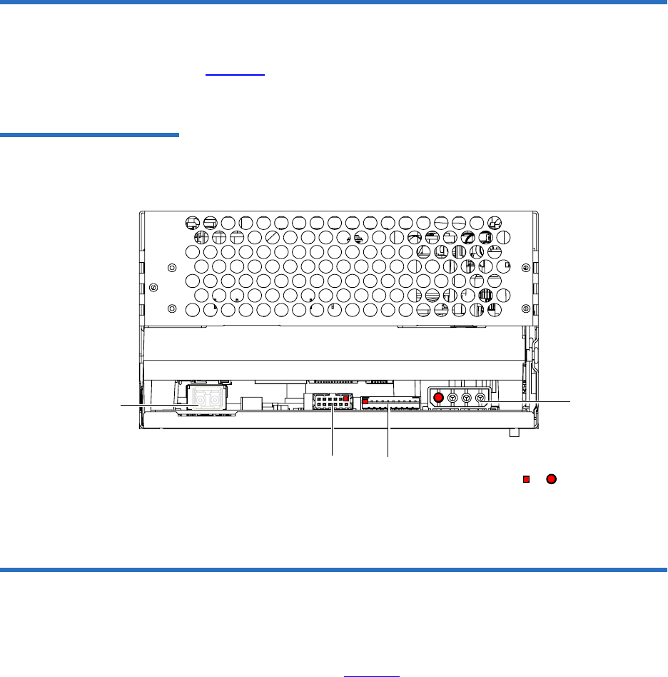
Chapter 7 Fibre Channel Interface
Rear Panel Connectors
DLT-S4 Product Manual 56
Rear Panel Connectors 7
Figure 17 shows the location of the connectors on the rear panel of the
DLT-S4 Fibre Channel configured internal tape drive.
Figure 17 Fibre Channel
Connectors and Jumper Block
(Rear View)
Fibre Channel Cable Connector 7
Fibre Channel models of the DLT-S4 tape drive (internal model only)
have one Fibre Channel port. The Fibre Channel cable connector looks
like the one shown in figure 18.
or denotes pin #1
Power
connector
(4-pin)
Loader/library interface
connector (10-pin)
Fibre Channel Jumper Block
Fibre Channel
port

Chapter 7 Fibre Channel Interface
Fibre Channel Tape Drive Features
DLT-S4 Product Manual 57
Figure 18 Fibre Channel Cable
Connector
Fibre Channel Tape Drive Features 7
The DLT-S4 Fibre Channel tape drive supports the following features:
• Automatic speed negotiation, with transfer rates of:
• 1 Gb per second
• 2 Gb per second
• 4 Gb per second
• Automatic topology negotiation (the tape drive operates as an
NL_Port or N_Port):
• Arbitrated Loop—private loop, NL_Port to NL_Ports(s)
• Arbitrated Loop—public loop, NL_Port to NL_Ports(s) and one
FL_Port.
• Fabric attachment—N_Port to F_Port
• Point-to-Point attachment—N_Port to N_Port
• FCP-2 (SCSI-3 command set) for tape devices
• Class 3 level of service
• Basic and extended link services
• Hard assigned port address, when attached to a library.
The library has the ability to assign a hard address to the tape drive. If
no hard address is assigned to the tape drive, then a soft address is
taken initially.

Chapter 7 Fibre Channel Interface
Practical Considerations
DLT-S4 Product Manual 58
Practical Considerations 7
This section describes considerations specific to the DLT-S4 Fibre
Channel tape drive.
Hot-Swappable Cables 7Fibre Channel cables are “hot swappable,” which means that you may
connect and disconnect them with unit power turned on. Therefore,
unlike some other systems, the tape drive and computer may remain
powered on while you connect the DLT-S4 tape drive to the host
computer.
Power Usage 7DLT-S4 Fibre Channel tape drives use slightly more power than SCSI-
configured tape drives. See the DLT-S4 Product Specification (81-81279-xx).
Power Cycle (Tape Drive
On) 7When the tape drive completes the power cycle process (including POST)
and the port is initialized, the Fibre Channel port is enabled and will
attempt to initialize on the attached Fibre Channel topology.
When the tape drive completes the power cycle process (tape drive
turned on and POST complete), the device is on-line and capable of tape
drive operations.
See Power-On Self-Test on page 113 for information about POST.
Failure to Obtain a Loop
Address 7If the tape drive is unable to obtain an address (fabric assigned,
previously assigned, hard assigned, or soft assigned), it goes into a non-
participating mode and immediately implicitly logs out all logged-in
ports.
If the tape drive experiences a power-on reset, or recognizes an
LIP (AL_PD, AL_PS), it does not retain a previously acquired address to
use during the next loop initialization.
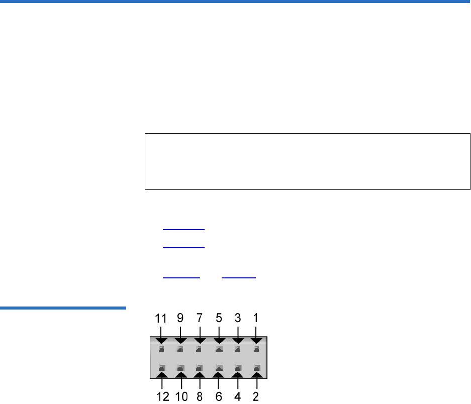
Chapter 7 Fibre Channel Interface
Fibre Channel Speed and Topology
DLT-S4 Product Manual 59
Fibre Channel Speed and Topology 7
Although Fibre Channel DLT-S4 tape drives will auto-negotiate the speed
and topology, you may override the automatic selections by placing
jumpers on the Fibre Channel jumper block at the rear of the tape drive.
If you decide it is necessary to change the tape drive’s speed or topology,
use your fingers to move the jumpers to the pattern corresponding to the
speed or topology you want. Using this jumper block is optional.
See:
•Figure 17 for the Fibre Channel jumper block location
•Figure 19 for the empty jumper block that you use to set the speed
and topology
•Table 32 and table 33 for the various jumper setting combinations
Figure 19 Fibre Channel
Speed and Topology Jumper
Block
Note: The tape drive only checks the jumpers at a power cycle. To
change the speed or topology configurations after installation,
turn off the tape drive, move the jumpers as needed, and then
turn on the tape drive.

Chapter 7 Fibre Channel Interface
Fibre Channel Speed and Topology
DLT-S4 Product Manual 60
Table 32 Fibre Channel Speed
Configuration
To Select This
Speed Put Jumper on
These Pins Result
1 Gb per second 7 and 8 Tape drive attempts to synchronize the link at 1 Gb per
second only
2 Gb per second 5 and 6 Tape drive attempts to synchronize the link at 2 Gb per
second only
4 Gb per second 3 and 4 Tape drive attempts to synchronize the link at 4 Gb per
second only
Auto-negotiate No jumpers Auto Speed Negotiate: Tape drive attempts to synchronize
• first at 4 Gb per second
•then at 2 Gb per second
• then at 1 Gb per second
5 and 6
AND
3 and 4
Auto Speed Negotiate: Tape drive attempts to synchronize
• first at 4 Gb per second
•then at 2 Gb per second
• then at 1 Gb per second
Note: Pins 1 and 2 are spare pins that are not used; there is no effect if they are jumpered or not
jumpered.

Chapter 7 Fibre Channel Interface
World-wide Names
DLT-S4 Product Manual 61
Table 33 Fibre Channel
Topology Configuration
World-wide Names 7
Each DLT-S4 tape drive contains two unique, 64-bit world-wide names: a
node name for the tape drive, and one for the tape drive’s Fibre Channel
port. The tape drive reports the world-wide names to the host through
the INQUIRY Command (12h). See the DLT-S4 Interface Reference Guide
(81-81281-xx) for more information.
To Select This
Topology Put Jumper on
These Pins Result
Arbitrated Loop 11 and 12 Tape drive attempts to initialize the link in FC Arbitrated
Loop topology only
Point-to-Point 9 and 10 Tape drive attempts to initialize the link in FC Point-to-Point
topology only
Auto-negotiate No jumpers Auto Topology: Tape drive attempts to
• first initialize in FC Arbitrated Loop topology
• then initialize in FC Point-to-Point topology
11 and 12
AND
9 and 10
Auto Topology: Tape drive attempts to
• first initialize in FC Arbitrated Loop topology
• then initialize in FC Point-to-Point topology
Note: Pins 1 and 2 are spare pins that are not used; there is no effect if they are jumpered or not
jumpered.

DLT-S4 Product Manual 62
Chapter 8
8Serial Attached SCSI (SAS)
Interface
This chapter provides SAS interface specifications associated with the
DLT-S4 tape drive, which include the following topics:
•Rear Panel Connectors
•SAS Cable Connector
•SAS Tape Drive Features
•Practical Considerations
•SAS Tape Drive Speed
•World-wide Names
The SAS interface is ONLY available with the internal and library models;
it is not available with the tabletop model.
For information on transfer rates and protocol options, see table 4 on
page 11.
For more information on the SAS interface, see the DLT-S4 Interface
Reference Guide (81-81281-xx).
Also, see the latest SAS reference documentation available at www.t10.org.
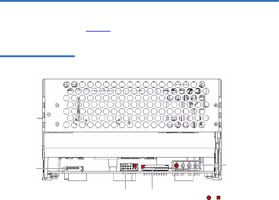
Chapter 8 Serial Attached SCSI (SAS) Interface
Rear Panel Connectors
DLT-S4 Product Manual 63
Rear Panel Connectors 8
Figure 20 shows the location of the connectors on the rear panel of the
DLT-S4 SAS configured internal tape drive.
Figure 20 SAS Connectors and
Jumper Block (Rear View)
SAS port
Loader/library interface
connector (10 pin)
Power
connector
(4 pin)
or denotes pin #1
Unused jumper
block
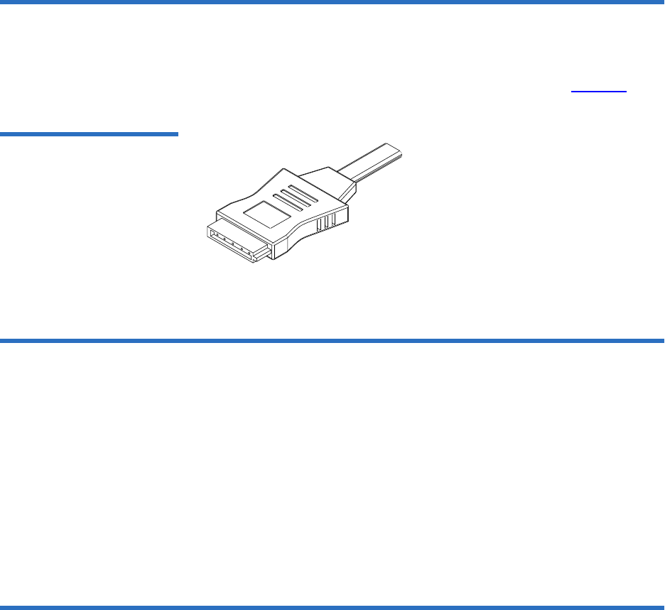
Chapter 8 Serial Attached SCSI (SAS) Interface
SAS Cable Connector
DLT-S4 Product Manual 64
SAS Cable Connector 8
SAS models of the DLT-S4 tape drive (internal model only) have one SAS
port. The SAS cable connector looks like the one shown in figure 21.
Figure 21 SAS Cable
Connector
SAS Tape Drive Features 8
The DLT S4 SAS tape drive supports the following features:
• Automatic speed negotiation, with speeds of:
• 1.5 Gb per second
• 3 Gb per second
•SAS-1.1
• Transport Layer Retries
Practical Considerations 8
SAS cables are “hot-swappable,” meaning that you may connect and
disconnect them with unit power turned on. Therefore, unlike some other
systems, the tape drive and computer may remain powered on while you
connect the DLT S4 tape drive to the host computer.

Chapter 8 Serial Attached SCSI (SAS) Interface
SAS Tape Drive Speed
DLT-S4 Product Manual 65
DLT S4 SAS tape drives use slightly more power than SCSI-configured
tape drives. See the DLT-S4 Product Specification (81-81279-xx) for
additional information.
SAS Tape Drive Speed 8
SAS DLT-S4 tape drives auto-negotiate the speed. The tape drive
attempts to synchronize:
• first at 3 Gb per second
• then at 1.5 Gb per second
World-wide Names 8
Each DLT-S4 tape drive contains two unique, 64-bit world-wide names: a
node name for the tape drive, and one for the tape drive’s SAS port. The
tape drive reports the world-wide names to the host through the INQUIRY
Command (12h). See the DLT-S4 Interface Reference Guide (81-81281-xx) for
more information.

DLT-S4 Product Manual 66
Chapter 9
9Installing an Internal
SCSI Tape Drive
This chapter describes how to configure and install the DLT-S4 internal
SCSI tape drive.
This chapter includes the following information:
•Equipment Required
•Installation Steps
•Rear Panel Connectors
•Unpacking the Tape Drive
•Setting the SCSI ID
•Securing the Tape Drive in the System
•Connecting the Cables and Terminating the SCSI Bus
•Setting TERMPWR
•Confirming the Installation
•Adding an Additional Device
•Using the Loader/Library Interface Connector
Caution: Before you begin, review the safety, ESD, and handling
precautions described in Chapter 2 to avoid personal
injury or damage to equipment.

Chapter 9 Installing an Internal SCSI Tape Drive
Equipment Required
DLT-S4 Product Manual 67
Equipment Required 9
You need the following items to install the tape drive in a system:
• Four (4) M3 x 8 mm long screws
• Screwdriver
• Jumpers (supplied)
• Internal Ultra320 SCSI cable, SPI-4 (or SPI-5) compatible
• Active Ultra320 SCSI terminator (if the SCSI cable is already
terminated at the end then you do not need this item)
Installation Steps 9
To install the tape drive, perform the following tasks in this order. Each
task is described in detail on the pages listed below.
Step No. Step Page
1Unpack the tape drive. Page 69
2Set the SCSI ID. Page 69
3Secure the tape drive in the system. Page 71
4Connect the cables and terminate the
SCSI bus.
Page 74
5Set TERMPWR. Page 77
6Confirm the installation. Page 78
7Add an additional device (optional). Page 78
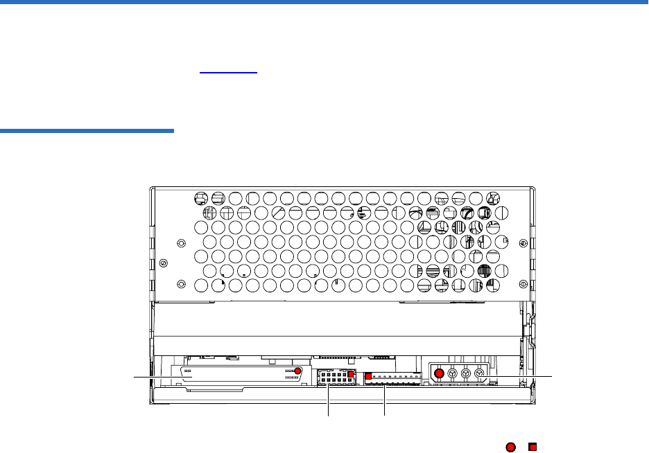
Chapter 9 Installing an Internal SCSI Tape Drive
Rear Panel Connectors
DLT-S4 Product Manual 68
Rear Panel Connectors 9
Figure 22 shows the location of the connectors on the rear panel of the
DLT-S4 SCSI configured internal tape drive.
Figure 22 SCSI Connectors
and Jumpers (Rear View)
Loader/library
interface connector
(10 pin)
SCSI ID jumper
block (includes
TERMPWR Enable) or denotes pin #1
Power
connector
(4 pin)
SCSI connector
(68 pin)

Chapter 9 Installing an Internal SCSI Tape Drive
Unpacking the Tape Drive
DLT-S4 Product Manual 69
Unpacking the Tape Drive 9
Before you begin, clear a desk or table so that you can unpack the tape
drive.
Unpack and inspect the tape drive for shipping damage. If you notice any
damage, report it both to the sales representative and to the shipping
company immediately.
If there is no damage to the tape drive, select a server or workstation to
host the tape drive, then move on to the following installation steps.
Setting the SCSI ID 9
Each device on the SCSI bus must have a unique SCSI ID address
assigned to it. Check the SCSI IDs on all other devices on the selected
server or workstation, including the SCSI host adapter, and select an
unused SCSI ID for the tape drive. The factory default SCSI ID for the
internal tape drive is 5 (no jumpers are installed on the jumper block). If
the tape drive’s factory default SCSI ID is not currently in use by another
device, you do not need to change the SCSI ID.
Note: If the room in which you are working differs from the
temperature at which the tape drive was shipped or stored by
30 ºF (17 ºC) or more, let the tape drive acclimate to the
surrounding environment for at least 12 hours before opening
the shipping carton.
Caution: Save the packing materials in case you need to move or
ship the tape drive in the future. When returning a unit to
Quantum for repair, you must use the original or
equivalent packing materials or risk voiding your
warranty.
Caution: If you reset the SCSI ID, do not use ID 7, as that ID is
already in use by the SCSI host adapter.
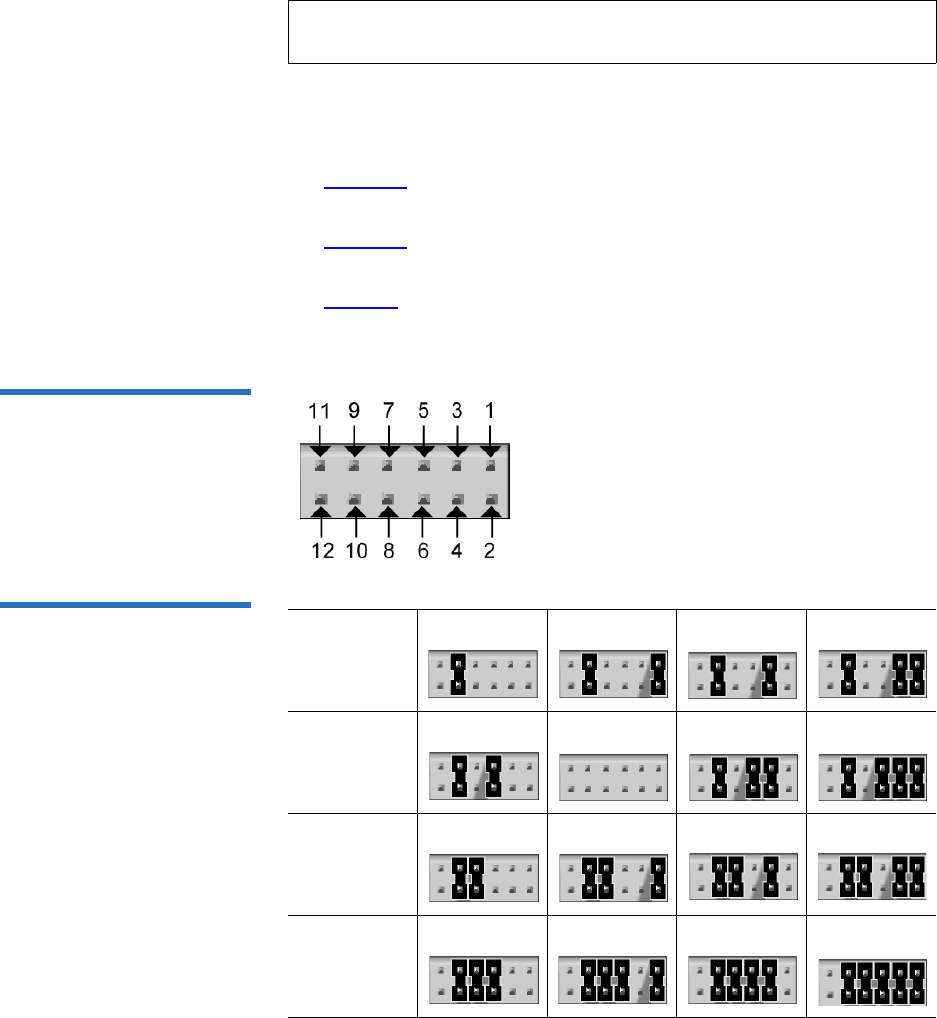
Chapter 9 Installing an Internal SCSI Tape Drive
Setting the SCSI ID
DLT-S4 Product Manual 70
You can set the SCSI ID from 0 to 15. To change the SCSI ID, use your
fingers to place the supplied jumpers on the 12-pin SCSI ID jumper block
as follows:
•Figure 22 shows the location of the jumper block on the rear panel of
the tape drive.
•Figure 23 shows the empty 12-pin jumper block that you use to set
the SCSI ID.
•Table 34 shows how to place the jumpers to obtain the desired SCSI
ID.
Figure 23 Detail of the Empty
SCSI ID Connector
Table 34 SCSI ID Address
Selections
Note: For specific recommendations for assigning SCSI IDs, refer to
the system or SCSI controller documentation.
SCSI ID
Jumper
Block
0123
SCSI ID
Jumper
Block
45 (default) 6 7
SCSI ID
Jumper
Block
89
10 11
SCSI ID
Jumper
Block
12 13 14 15

Chapter 9 Installing an Internal SCSI Tape Drive
Securing the Tape Drive in the System
DLT-S4 Product Manual 71
Securing the Tape Drive in the System 9
This section describes how to mount and secure the tape drive in the
system. Because of the variety of mounting possibilities for tape drives,
the instructions presented here are general guidelines. Use these
instructions only as a guide for mounting the tape drive in the system.
Mount the tape drive in the system by performing the following steps:
1Ensure that the host computer and all peripheral devices are turned
off.
2Position the tape drive in the system and align the tape drive
mounting holes (side or bottom) with those in the system (see
figure 24 and figure 25).
3Secure the tape drive in the bay or chassis using four M3 x 8mm long
screws.
Note: The computer system and the tape drive SCSI IDs are only
checked when you turn both the computer system and the
tape drive off and then on again. To change the SCSI ID after
installation, turn off the system, change the tape drive’s SCSI
ID, and then turn on the system.
Note: In some system configurations, it may be more convenient to
connect the SCSI bus and power cables to the tape drive before
securing it in the system.
Caution: The screws used to mount the tape drive must be
M3 x 8mm long. This kind of screw is exactly the
proper length and will not damage the tape drive.
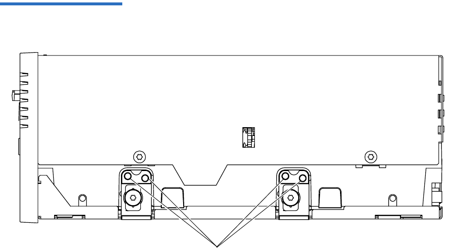
Chapter 9 Installing an Internal SCSI Tape Drive
Securing the Tape Drive in the System
DLT-S4 Product Manual 72
Figure 24 Tape Drive Mounting
Holes — Right Side View
Mounting holes
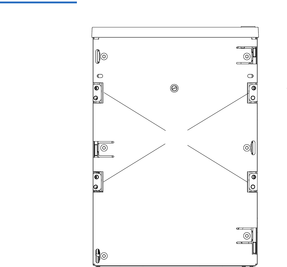
Chapter 9 Installing an Internal SCSI Tape Drive
Securing the Tape Drive in the System
DLT-S4 Product Manual 73
Figure 25 Tape Drive Mounting
Holes — Bottom View
Mounting
holes

Chapter 9 Installing an Internal SCSI Tape Drive
Connecting the Cables and Terminating the SCSI Bus
DLT-S4 Product Manual 74
Connecting the Cables and Terminating the SCSI Bus 9
You can connect the DLT-S4 tape drive to the host computer as a single
device, or as one of two total devices connected via a SCSI cable with
multiple SCSI connectors in a “chain” configuration.
If you are connecting two devices to the SCSI bus, connect only one tape
drive to the host computer at this time. Finish the installation procedure
and confirm that the host computer and tape drive are communicating
correctly (see Confirming the Installation) before adding the additional
device (see Adding an Additional Device).
Follow these steps to connect the tape drive to the host computer (see
SCSI Connectors and Pin Assignments on page 51 for more information).
1Ensure that the tape drive, host computer, and all peripheral devices
(such as printers) are turned off.
2Disconnect any other SCSI devices from the SCSI bus at this time.
You can add them back on later (see Adding an Additional Device).
3Ensure that the SCSI cable(s) and terminator(s) are Ultra320 and SPI-4
(or SPI-5) compatible.
4Terminate the SCSI bus by making sure a terminator is installed in
the very last connector of the SCSI cable.
Note: Use care when connecting the cables to avoid bending or
damaging the connector pins.
Caution: Never connect the tape drive while the tape drive,
host system, or peripheral devices are turned on.
Doing so could result in damage to the tape drive or
other peripheral devices.
Note: SPI refers to SCSI Parallel Interface; you can learn more
from this standard at the Web site www.t10.org.
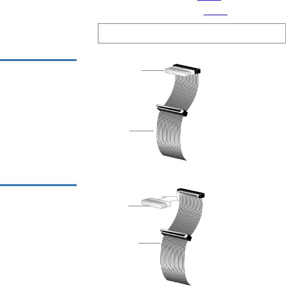
Chapter 9 Installing an Internal SCSI Tape Drive
Connecting the Cables and Terminating the SCSI Bus
DLT-S4 Product Manual 75
If the SCSI cable you are using has a built-in terminator, you do not
need to add another terminator (see figure 26 for an example of such
a cable). If the cable is not terminated, then install an active Ultra320
SCSI terminator on the SCSI cable (see figure 27).
Figure 26 SCSI Cable with
Built-in Terminator
Figure 27 SCSI Interface –
Terminator Installation
Note: There should be only one terminator at the end of the SCSI
bus.
SCSI cable
Built-in
terminator
Terminator
SCSI cable
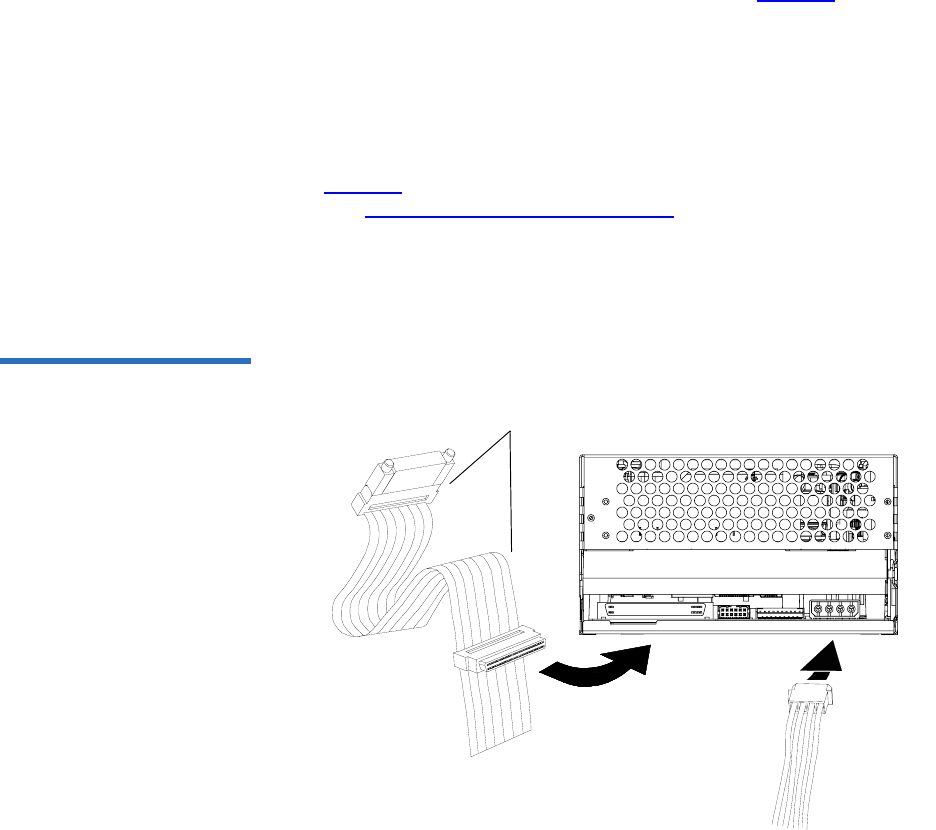
Chapter 9 Installing an Internal SCSI Tape Drive
Connecting the Cables and Terminating the SCSI Bus
DLT-S4 Product Manual 76
5Connect one of the SCSI connectors on the SCSI cable to the SCSI
connector on the rear panel of the tape drive (see figure 28). The SCSI
connectors are keyed, preventing improper connection.
6If not already connected, connect the other end of the SCSI cable to
the connector in the SCSI host adapter, aligning the colored stripe on
the cable with pin 1 on the SCSI host adapter’s connector.
7Locate an available DC power cable in the host computer and attach
it to the power connector on the rear panel of the tape drive (see
figure 28). The connector is keyed, preventing improper connection.
(See Power Connector Pin Assignments on page 46 for power pin
number assignments and signal names.)
8Check all the cable and termination connections to ensure that they
are attached correctly, seated firmly, and secured.
Figure 28 SCSI and Power
Cable Locations SCSI cable (shown with
terminator installed)
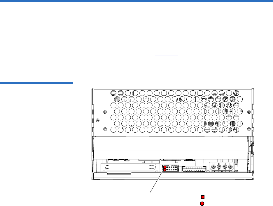
Chapter 9 Installing an Internal SCSI Tape Drive
Setting TERMPWR
DLT-S4 Product Manual 77
Setting TERMPWR 9
At least one device on the bus must supply terminator power
(TERMPWR).
• To enable TERMPWR — Install a jumper across pins 11 and 12 on the
SCSI jumper block (see figure 29).
• To disable TERMPWR — Remove the jumper.
Figure 29 Enabling TERMPWR
TERMPWR Enable jumper
on jumper block denotes pin #12
denotes pin #11

Chapter 9 Installing an Internal SCSI Tape Drive
Confirming the Installation
DLT-S4 Product Manual 78
Confirming the Installation 9
To confirm the installation, turn on the host computer.
The screens displayed at power-on contain:
•BIOS
•Operating system
• SCSI controller information
If the first screen displays host adapter and SCSI ID information
indicating the drive is a Quantum product, then the installation was
successful.
If the installation was NOT successful, see POST and SCSI
Troubleshooting on page 124.
Adding an Additional Device 9
Once you have successfully confirmed the installation of your tape drive,
you may add one additional device to the SCSI bus.
1Ensure that all devices have unique SCSI IDs (see Setting the SCSI ID
on page 69).
2Ensure that the tape drive, host computer, and all peripheral devices
(such as printers) are turned off.
3Make sure that all the SCSI cables and terminators are SPI-4 (or SPI-5)
compatible.
Note: Use care when connecting the cables to avoid bending or
damaging the connector pins.
Caution: Never connect the tape drive while the tape drive,
host system, or peripheral devices are turned on.
Doing so could result in damage to the tape drive or
other peripheral devices.

Chapter 9 Installing an Internal SCSI Tape Drive
Using the Loader/Library Interface Connector
DLT-S4 Product Manual 79
4Connect all additional tape drives and peripheral devices to the host
computer’s SCSI cable.
5Ensure that a terminator is installed on the very last SCSI connector
on the SCSI cable.
6Check all the cable and termination connections to ensure that they
are attached correctly and seated firmly.
7Turn on power to the system and all attached devices.
8Confirm the installation (see Confirming the Installation on page 78).
Using the Loader/Library Interface Connector 9
This connector is only used for tape drives installed in loaders/libraries.
If your system requires it to be used, it should have been pre-assembled
at the factory. For more information about the loader/library connector,
see Loader/Library Interface Connector on page 46.
Note: Regardless of which device terminates the SCSI bus, that
device must have power applied and be powered on for
proper termination to occur.

DLT-S4 Product Manual 80
Chapter 10
10Installing an Internal Fibre
Channel Tape Drive
This chapter describes how to configure and install the DLT-S4 internal
Fibre Channel tape drive.
This chapter includes the following information:
•Equipment Required
•Installation Steps
•Rear Panel Connectors
•Unpacking the Tape Drive
•Securing the Tape Drive in the System
•Connecting the Cables
•Confirming the Installation
•Adding Additional Devices
•Using the Loader/Library Interface Connector
Caution: Before you begin, review the safety, ESD, and handling
precautions described in Chapter 2 to avoid personal
injury or damage to equipment.

Chapter 10 Installing an Internal Fibre Channel Tape Drive
Equipment Required
DLT-S4 Product Manual 81
Equipment Required 10
You need the following items to install the tape drive in a system:
• Four (4) M3 x 8 mm long screws
• Screwdriver
• Fiber optic cable
Installation Steps 10
To install the tape drive, perform the following tasks in this order. Each
task is described in detail on the pages listed below.
Step No. Step Page
1Unpack the tape drive. Page 83
2Secure the tape drive in the system. Page 83
3Connect the cable. Page 86
4Confirm the installation. Page 87
5Add additional devices (optional). Page 88
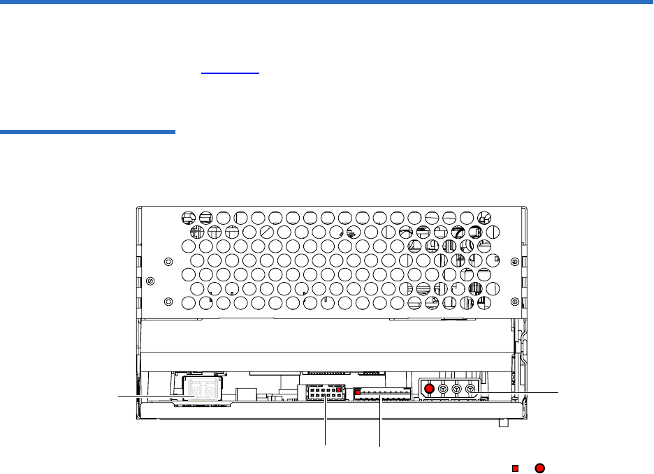
Chapter 10 Installing an Internal Fibre Channel Tape Drive
Rear Panel Connectors
DLT-S4 Product Manual 82
Rear Panel Connectors 10
Figure 30 shows the location of the connectors on the rear panel of the
DLT-S4 Fibre Channel internal tape drive.
Figure 30 Fibre Channel
Connectors and Jumper Block
(Rear View)
or denotes pin #1
Power
connector
(4-pin)
Loader/library interface
connector (10-pin)
Fibre Channel Jumper Block
Fibre Channel
port

Chapter 10 Installing an Internal Fibre Channel Tape Drive
Unpacking the Tape Drive
DLT-S4 Product Manual 83
Unpacking the Tape Drive 10
Before you begin, clear a desk or table so that you can unpack the tape
drive.
Unpack and inspect the tape drive for shipping damage. If you notice any
damage, report it both to the sales representative and to the shipping
company immediately.
If there is no damage to the tape drive, select a server or workstation to
host the tape drive, then move on to the following installation steps.
Securing the Tape Drive in the System 10
This section describes how to mount and secure the tape drive in the
system. Because of the variety of mounting possibilities for tape drives,
the instructions presented here are general guidelines. Use them only as a
guide for mounting the tape drive in the system.
Note: If the room in which you are working differs from the
temperature at which the tape drive was shipped or stored by
30 ºF (17 ºC) or more, let the tape drive acclimate to the
surrounding environment for at least 12 hours before opening
the shipping carton.
Caution: Save the packing materials in case you need to move or
ship the tape drive in the future. When returning a unit to
Quantum for repair, you must use the original or
equivalent packing materials or risk voiding your
warranty.
Note: In some system configurations it may be more convenient to
connect the Fibre Channel and power cables to the tape drive
before securing it in the system.
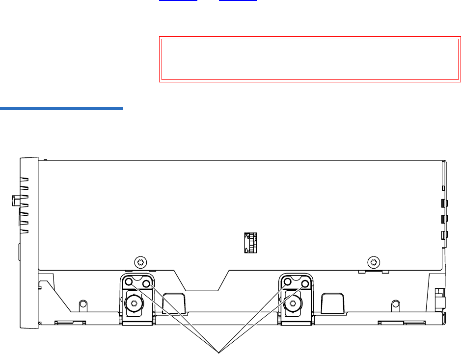
Chapter 10 Installing an Internal Fibre Channel Tape Drive
Securing the Tape Drive in the System
DLT-S4 Product Manual 84
Mount the tape drive in the system by performing the following steps:
1Ensure that the host computer and all peripheral devices are turned
off.
2Position the tape drive in the system and align the tape drive
mounting holes (side or bottom) with those in the system (see
figure 31 and figure 32).
3Secure the tape drive in the bay or chassis using four M3 x 8mm long
screws.
Figure 31 Tape Drive Mounting
Holes — Right Side View
Caution: The screws used to mount the tape drive must be
M3 x 8mm long. This kind of screw is exactly the
proper length and will not damage the tape drive.
Mounting holes
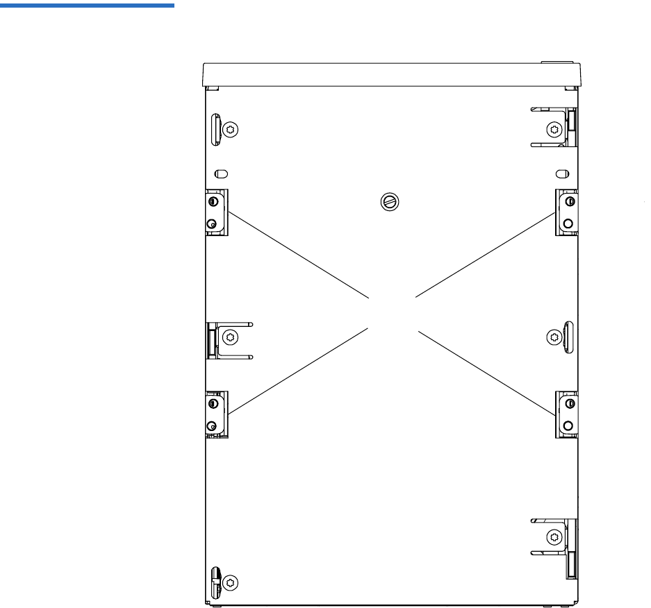
Chapter 10 Installing an Internal Fibre Channel Tape Drive
Securing the Tape Drive in the System
DLT-S4 Product Manual 85
Figure 32 Tape Drive Mounting
Holes — Bottom View
Mounting
holes

Chapter 10 Installing an Internal Fibre Channel Tape Drive
Connecting the Cables
DLT-S4 Product Manual 86
Connecting the Cables 10
Connect the Fibre Channel and power cables as follows:
1Ensure that both the tape drive and computer are turned off.
2Insert the fiber optic cable into the Fibre Channel port on the rear of
the tape drive (see figure 33).
The connector is fully seated when it snaps into the port.
3Insert the other end of the fiber optic cable into the Fibre Channel
port on the host computer.
4Locate an available DC power cable in the host computer and attach
it to the power connector on the rear panel of the tape drive (see
figure 33). The connector is keyed, preventing improper connection.
(See Power Connector Pin Assignments on page 46 for power pin
number assignments and signal names.)
5Check all cable connections to ensure that they are attached correctly,
seated firmly, and secured.
Note: If you are connecting several devices to the system,
connect only the tape drive to the host computer at this
time. Finish the installation procedure and confirm that
the host computer and tape drive are communicating
correctly before adding additional devices (see Adding
Additional Devices on page 88).
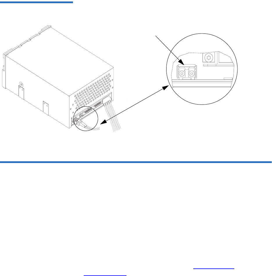
Chapter 10 Installing an Internal Fibre Channel Tape Drive
Confirming the Installation
DLT-S4 Product Manual 87
Figure 33 Connecting the Fibre
Channel and Power Cables
Confirming the Installation 10
To confirm the installation, turn on the host computer.
The screens displayed at power-on contain:
•BIOS
•Operating system
• SCSI controller information
If the first screen displays host adapter and SCSI ID information
indicating the drive is a Quantum product, then the installation was
successful.
If the installation was NOT successful, see POST and SCSI
Troubleshooting on page 124.
Fibre Channel port
Detail of the empty Fibre
Channel port

Chapter 10 Installing an Internal Fibre Channel Tape Drive
Adding Additional Devices
DLT-S4 Product Manual 88
Adding Additional Devices 10
Once you have successfully confirmed the installation of your tape drive,
you may add additional devices.
For each additional device:
1Ensure that both the tape drive and computer are turned off.
2Insert the fiber optic cable into the Fibre Channel port on the device
(for tape drives see figure 33).
The connector is fully seated when it snaps into the port.
3Insert the other end of the fiber optic cable into the Fibre Channel
port on the host computer.
4Check all cable connections and ensure that they are attached
correctly and seated firmly before turning the system on.
5Confirm the installation (see Confirming the Installation on page 87).
Using the Loader/Library Interface Connector 10
This connector is only used for tape drives installed in loaders/libraries.
If your system requires it to be used, it should have been pre-assembled
at the factory. For more information about the loader/library connector,
see Loader/Library Interface Connector on page 46.

DLT-S4 Product Manual 89
Chapter 11
11Installing an Internal SAS
Tape Drive
This chapter describes how to configure and install the DLT-S4 internal
SCSI tape drive.
This chapter includes the following information:
•Equipment Required
•Installation Steps
•Rear Panel Connectors
•Unpacking the Tape Drive
•Securing the Tape Drive in the System
•Connecting the Cables
•Confirming the Installation
•Adding Additional Devices
•Using the Loader/Library Interface Connector
Caution: Before you begin, review the safety, ESD, and handling
precautions described in Chapter 2 to avoid personal
injury or damage to equipment.

Chapter 11 Installing an Internal SAS Tape Drive
Equipment Required
DLT-S4 Product Manual 90
Equipment Required 11
You need the following items to install the tape drive in a system:
• Four (4) M3 x 8 mm long screws
• Screwdriver
•SAS cable
Installation Steps 11
To install the tape drive, perform the following tasks in this order. Each
task is described in detail on the pages listed below.
Step No. Step Page
1Unpack the tape drive. Page 92
2Secure the tape drive in the system. Page 92
3Connect the cables. Page 95
4Confirm the installation. Page 96
5Add additional devices (optional). Page 97
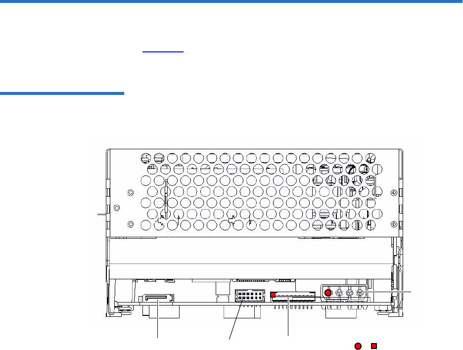
Chapter 11 Installing an Internal SAS Tape Drive
Rear Panel Connectors
DLT-S4 Product Manual 91
Rear Panel Connectors 11
Figure 34 shows the location of the connectors on the rear panel of the
SAS configured internal tape drive.
Figure 34 SAS Connectors and
Jumpers (Rear View)
SAS
connector Loader/library interface
connector (10 pin)
Power
connector
(4 pin)
or denotes pin #1
Unused
jumper block

Chapter 11 Installing an Internal SAS Tape Drive
Unpacking the Tape Drive
DLT-S4 Product Manual 92
Unpacking the Tape Drive 11
Before you begin, clear a desk or table so that you can unpack the tape
drive.
Unpack and inspect the tape drive for shipping damage. If you notice any
damage, report it both to the sales representative and to the shipping
company immediately.
If there is no damage to the tape drive, select a server or workstation to
host the tape drive, then move on to the following installation steps.
Securing the Tape Drive in the System 11
This section describes how to mount and secure the tape drive in the
system. Because of the variety of mounting possibilities for tape drives,
the instructions presented here are general guidelines. Use them only as a
guide for mounting the tape drive in the system.
Mount the tape drive in the system by performing the following steps:
Note: If the room in which you are working differs from the
temperature at which the tape drive was shipped or stored by
30 ºF (17 ºC) or more, let the tape drive acclimate to the
surrounding environment for at least 12 hours before opening
the shipping carton.
Caution: Save the packing materials in case you need to move or
ship the tape drive in the future. When returning a unit to
Quantum for repair, you must use the original or
equivalent packing materials or risk voiding your
warranty.
Note: In some system configurations it may be more convenient to
connect the SAS and power cables to the tape drive before
securing it in the system.

Chapter 11 Installing an Internal SAS Tape Drive
Securing the Tape Drive in the System
DLT-S4 Product Manual 93
1Ensure that the host computer and all peripheral devices are turned
off.
2Position the tape drive in the system and align the tape drive
mounting holes (side or bottom) with those in the system (see
figure 35 and figure 36).
3Secure the tape drive in the bay or chassis using four M3 x 8mm long
screws.
Figure 35 Tape Drive Mounting
Holes — Right Side View
Caution: The screws used to mount the tape drive must be
M3 x 8mm long. This kind of screw is exactly the
proper length and will not damage the tape drive.
Mounting holes

Chapter 11 Installing an Internal SAS Tape Drive
Securing the Tape Drive in the System
DLT-S4 Product Manual 94
Figure 36 Tape Drive Mounting
Holes — Bottom View
Mounting
holes

Chapter 11 Installing an Internal SAS Tape Drive
Connecting the Cables
DLT-S4 Product Manual 95
Connecting the Cables 11
Connect the SAS and power cables as follows:
1Ensure that both the tape drive and computer are turned off.
2Insert the SAS cable into the SAS port on the rear of the tape drive
(see figure 34).
3Insert the other end of the SAS cable into the SAS port on the host
computer.
4Locate an available DC power cable in the host computer and attach
it to the power connector on the rear panel of the tape drive (see
figure 37). The connector is keyed, preventing improper connection.
(See Power Connector Pin Assignments on page 46 for power pin
number assignments and signal names.)
5Check all the cable and termination connections to ensure that they
are attached correctly, seated firmly, and secured.
Note: If you are connecting several devices to the system,
connect only the tape drive to the host computer at this
time. Finish the installation procedure and confirm that
the host computer and tape drive are communicating
correctly before adding additional devices (see
Confirming the Installation on page 96).
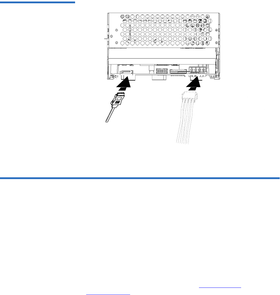
Chapter 11 Installing an Internal SAS Tape Drive
Confirming the Installation
DLT-S4 Product Manual 96
Figure 37 Connecting the SAS
and Power Cables
Confirming the Installation 11
To confirm the installation, turn on the host computer.
The screens displayed at power-on contain:
•BIOS
•Operating system
• SCSI controller information
If the first screen displays host adapter and SCSI ID information
indicating the drive is a Quantum product, then the installation was
successful.
If the installation was NOT successful, see POST and SCSI
Troubleshooting on page 124.

Chapter 11 Installing an Internal SAS Tape Drive
Adding Additional Devices
DLT-S4 Product Manual 97
Adding Additional Devices 11
Once you have successfully confirmed the installation of your tape drive,
you may add additional devices.
For each additional device:
1Ensure that both the tape drive and host computer are turned off.
2Insert the SAS cable into the SAS port on the device (for tape drives,
see figure 34).
3Insert the other end of the SAS cable into the SAS port on the host
computer.
4Check all cable connections and ensure that they are attached
correctly and seated firmly before turning the system on.
5Confirm the installation (see Confirming the Installation on page 96).
Using the Loader/Library Interface Connector 11
This connector is only used for tape drives installed in loaders/libraries.
If your system requires it to be used, it should have been pre-assembled
at the factory. For more information about the loader/library connector,
see Loader/Library Interface Connector on page 46.

DLT-S4 Product Manual 98
Chapter 12
12Installing the Tabletop
Tape Drive
This chapter describes how to configure and install the DLT-S4 tabletop
tape drive.
This chapter includes the following information:
•Equipment Required
•Installation Steps
•Rear Panel Connectors
•Unpacking the Tabletop Tape Drive
•Selecting a Location for the Tabletop Tape Drive
•Setting the SCSI ID
•Connecting the Tape Drive to the Host Computer and Terminating
the SCSI Bus
•Connecting the AC Power Cable
•Confirming the Installation
•Adding an Additional Device
•Configuring the Tape Drive
•Using TERMPWR

Chapter 12 Installing the Tabletop Tape Drive
Equipment Required
DLT-S4 Product Manual 99
Equipment Required 12
You need the following items to install the tape drive in a system:
• Four (4) M3 x 8 mm long screws
• Screwdriver
• Ultra320-rated SCSI cable and terminator (supplied)
• Ultra320-capable host bus adapter (HBA)
Installation Steps 12
To install the tape drive, perform the following tasks in this order. Each
task is described in detail on the pages listed below.
Caution: Before you begin, review the safety, ESD, and handling
precautions described in Chapter 2 to avoid personal
injury or damage to equipment.
Note: The tabletop model comes ONLY with the SCSI interface. The
Fibre Channel and SAS interfaces are not available.
Step No. Step Page
1Unpack the tape drive. Page 101
2Select a location for the tape drive. Page 101
3Set the SCSI ID. Page 102
4Connect the tape drive to the host
computer and terminate the SCSI bus.
Page 103
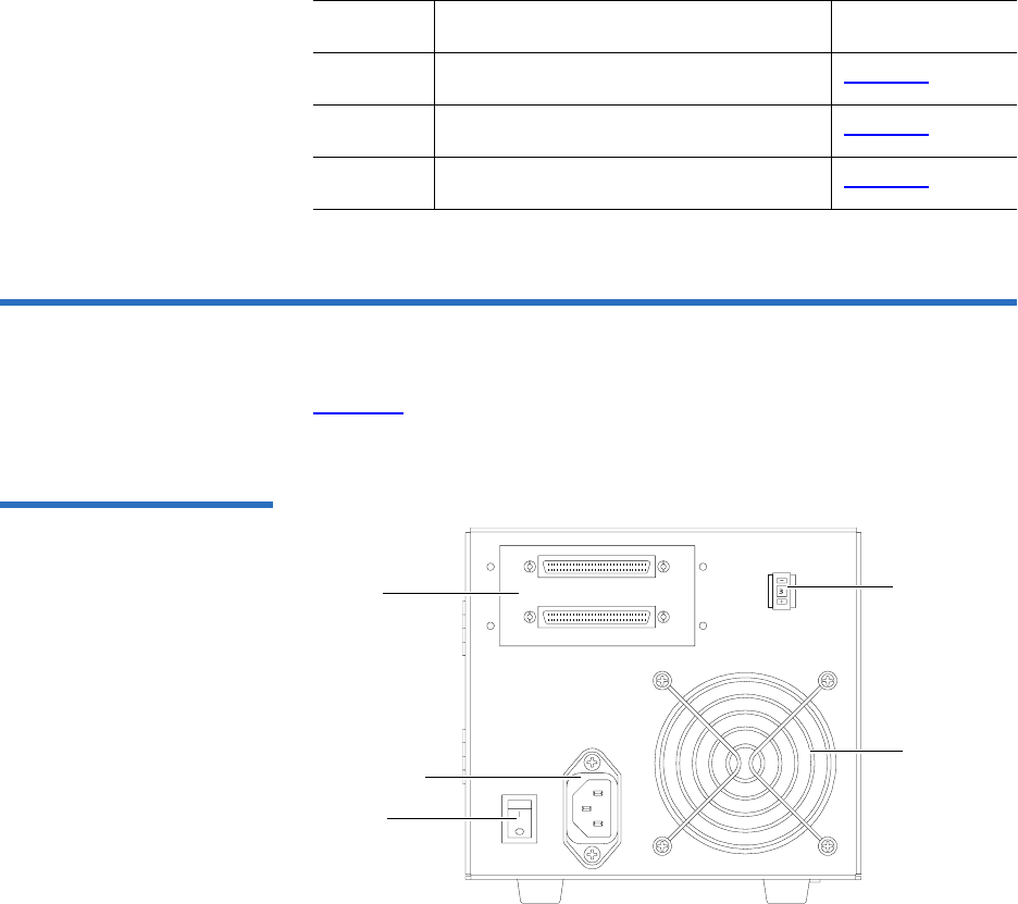
Chapter 12 Installing the Tabletop Tape Drive
Rear Panel Connectors
DLT-S4 Product Manual 100
Rear Panel Connectors 12
Figure 38 shows the location of the connectors on the rear panel of the
DLT-S4 tabletop tape drive.
Figure 38 Tabletop Tape Drive
— Rear View
5Connect the AC power cable. Page 105
6Confirm the installation. Page 107
7Add an additional device (optional). Page 107
Step No. Step Page
Power
connector
Power
switch
SCSI
connectors
SCSI ID
selector
switch
Fan

Chapter 12 Installing the Tabletop Tape Drive
Unpacking the Tabletop Tape Drive
DLT-S4 Product Manual 101
Unpacking the Tabletop Tape Drive 12
Before you begin, clear a desk or table so that you can unpack the tape
drive.
Unpack and inspect the tape drive for shipping damage. If you notice any
damage, report it both to the sales representative and to the shipping
company immediately.
Selecting a Location for the Tabletop Tape Drive 12
Select a location for the tape drive that is flat, sturdy, level, and close to
the server or workstation. There should be sufficient room for the tape
drive to sit without being crowded. A desk or tabletop surface is most
suitable. Regardless of the location you choose for the tape drive, make
sure the environment is free from dust, cigarette smoke, and excessive
temperature and humidity. See the Physical Specifications on page 38 for
acceptable operating temperature and humidity limits.
Be sure to follow these additional guidelines when selecting a location for
the tape drive:
• Allow at least 6 inches (15.2 cm) behind the tape drive for proper
cooling.
Note: If the room in which you are working differs from the
temperature at which the tape drive was shipped or stored by
30 ºF (17 ºC) or more, let the tape drive acclimate to the
surrounding environment for at least 12 hours before opening
the shipping carton.
Caution: Save the packing materials in case you need to move or
ship the tape drive in the future. When returning a unit to
Quantum for repair, you must use the original or
equivalent packing materials or risk voiding your
warranty.
Chapter 12 Installing the Tabletop Tape Drive
Setting the SCSI ID
DLT-S4 Product Manual 102
• Avoid locations near printers or photocopy machines, both of which
produce paper fiber and other types of dust and airborne
contaminants.
• Do not place the tape drive on the floor.
• Avoid locations near generators, electric motors, audio speakers, or
other sources of magnetic fields. Magnetic fields can adversely affect
the tape drive and data cartridges.
Setting the SCSI ID 12
Each device connected to a SCSI bus must have a unique SDSI ID. Check
the SCSI IDs on all other devices on the selected server or workstation,
including the SCSI host adapter, and select an unused SCSI ID for the
tape drive. The factory default SCSI ID for the tabletop tape drive is 3. If
the tape drive’s factory default SCSI ID is not already in use by another
device on the same SCSI bus, you do not need to change the SCSI ID.
You can configure the tape drive for SCSI ID addresses that range from 0
to 15 using the SCSI ID selector switch push buttons (see figure 39 for a
close-up view of the SCSI ID switch and its location on the rear of the
tabletop tape drive).
To change the SCSI ID, use a small screwdriver or ballpoint pen to press
the buttons until the desired SCSI ID appears in the display.
• To decrease the ID number — Press the button above the number.
• To increase the ID number — Press the button below the number.
Caution: If you reset the SCSI ID, do not use ID 7, as that ID is
already in use by the SCSI host adapter.
Note: For specific recommendations for assigning SCSI IDs, refer to
the system or SCSI controller documentation.
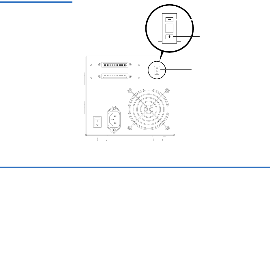
Chapter 12 Installing the Tabletop Tape Drive
Connecting the Tape Drive to the Host Computer and Terminating the SCSI Bus
DLT-S4 Product Manual 103
Figure 39 Tabletop SCSI ID
Selector Switch
Connecting the Tape Drive to the Host Computer and
Terminating the SCSI Bus 12
You can connect the DLT-S4 tape drive to the host computer as a single
device, or as one of a maximum of two devices connected via SCSI cables
in a “daisy chain” configuration.
If you are connecting two devices to the SCSI bus, connect only the tape
drive to the host computer at this time. Finish the installation procedure
and confirm that the host computer and tape drive are communicating
correctly (see Confirming the Installation) before adding an additional
device (see Adding an Additional Device).
3
SCSI ID
selector
switch
Press here to decrease
SCSI ID
Press here to increase
SCSI ID

Chapter 12 Installing the Tabletop Tape Drive
Connecting the Tape Drive to the Host Computer and Terminating the SCSI Bus
DLT-S4 Product Manual 104
Follow these steps to connect the tape drive to the host computer (see
SCSI Connectors and Pin Assignments on page 51 for more information):
1Ensure that the tape drive, host computer, and all peripheral devices
(such as printers) are turned off.
2Make sure that the SCSI cables and terminators are Ultra320 and
SPI-4 (or SPI-5) compatible.
3Terminate the SCSI bus by attaching a SCSI terminator to either of the
connectors on the rear of the tape drive (see figure 40).
4Carefully connect one end of the SCSI cable into the open SCSI
connector on the rear of the tape drive (see figure 40).
5Carefully connect the other end of the SCSI cable to the SCSI
connector on the host computer (see figure 40).
6Check all the cable and termination connections to ensure that they
are attached correctly, seated firmly, and secure.
Note: Use care when connecting the cables to avoid bending or
damaging the connector pins.
Caution: Never connect the tape drive while the tape drive,
host system, or peripheral devices are turned on.
Doing so could result in damage to the tape drive or
other peripheral devices.
Note: SPI refers to SCSI Parallel Interface; you can learn more
from this standard at the Web site www.t10.org.
Note: Regardless of which device terminates the SCSI bus, that
device must have power applied and be powered on for
proper termination to occur.
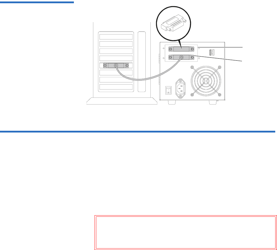
Chapter 12 Installing the Tabletop Tape Drive
Connecting the AC Power Cable
DLT-S4 Product Manual 105
Figure 40 SCSI Chain —
Single Device
Connecting the AC Power Cable 12
An AC power cable is supplied with each tabletop unit. The tabletop unit
power supply has an auto-sensing feature; it requires no adjustment or
switch setting changes for different AC sources.
To connect the AC power cable:
1Carefully inspect the power cable and ensure that the cable is the
appropriate cable for your country or region based on the following
criteria.
The AC power cable used with the tabletop unit must meet the
following criteria:
• The power cable should be a minimum of 18/3 AWG, 60 °C, type
SJT or SVT.
Warning: Do not attempt to modify or use a tabletop
100-115 V AC power cable for 220–240 V AC input
power. Modifying the power cable in any way can
cause personal injury and severe equipment damage.
SCSI
terminator
SCSI cable
connection
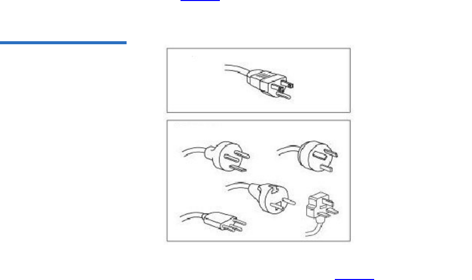
Chapter 12 Installing the Tabletop Tape Drive
Connecting the AC Power Cable
DLT-S4 Product Manual 106
• The cable must be UL and CSA certified cordage rated for use at
250 V AC with a current rating that is at least 125% of the current
rating of the product.
• You must terminate the AC plug in a grounding-type male plug
designed for use in your country or region. It must also have
marks showing certification by an agency acceptable in your
country or region.
• The tabletop unit cable connector must be an IEC type CEE-22
female connector.
• The cable must be no longer than 4.5 meters (14.5 feet).
• The cable must be FCC compliant with emissions specifications.
See figure 41 for the AC power cable plug-end types for 115 V AC and
220 V/240 V AC usage.
Figure 41 AC Power Cable
Connector Types
2Connect one end of the AC power cable into the power connector on
the rear of the tabletop tape drive (see figure 38 on page 100).
3Connect the other end of the power cable to the AC outlet.
115V
220V / 240V

Chapter 12 Installing the Tabletop Tape Drive
Confirming the Installation
DLT-S4 Product Manual 107
Confirming the Installation 12
To confirm the installation:
1Turn on the DLT-S4 tabletop tape drive.
2Turn on the host computer.
The screens displayed at power-on contain:
•BIOS
•Operating system
• SCSI controller information
If the first screen displays host adapter and SCSI ID information
indicating the drive is a Quantum product, then the installation was
successful.
If the installation was NOT successful, see POST and SCSI
Troubleshooting on page 124.
Adding an Additional Device 12
Once you have successfully confirmed the installation of your tape drive,
you may add another device (you may have a maximum of two devices)
to the SCSI bus.
Follow these steps to install the tape drive as a daisy-chain connection:
1Ensure that all SCSI devices have unique SCSI IDs (see Setting the
SCSI ID on page 102).
Note: Use care when connecting the cables to avoid bending or
damaging the connector pins.

Chapter 12 Installing the Tabletop Tape Drive
Adding an Additional Device
DLT-S4 Product Manual 108
2Ensure that the tape drive, host computer, and all peripheral devices
(such as printers) are turned off.
3Connect the SCSI cable from the host computer to the lower SCSI
connector on the rear of the tape drive (see figure 42).
4Continue the SCSI chain using the upper SCSI connector (see
figure 42).
5Make sure that all the SCSI cables and terminators are SPI-4 (or SPI-5)
compatible.
6Terminate the last device on the SCSI bus by attaching a SCSI
terminator on the upper SCSI connector of the last device (see
figure 42).
7Check all the cable and termination connections to ensure that they
are attached correctly, seated firmly, and secure.
Caution: Never connect the tape drive while the tape drive,
host system, or peripheral devices are turned on.
Doing so could result in damage to the tape drive or
other peripheral devices.
Note: Regardless of which device terminates the SCSI bus, that
device must have power applied and be powered on for
proper termination to occur.
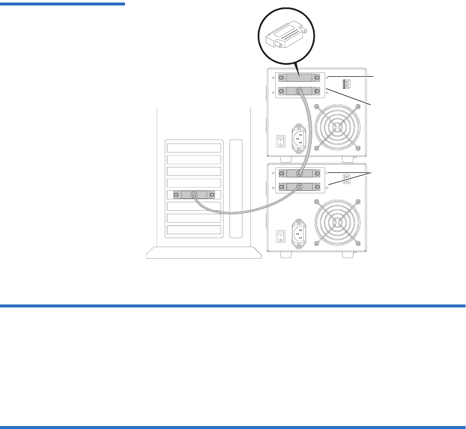
Chapter 12 Installing the Tabletop Tape Drive
Configuring the Tape Drive
DLT-S4 Product Manual 109
Figure 42 SCSI Chain —
Multiple Devices
Configuring the Tape Drive 12
This model of tape drive is normally configured to meet customer
specifications before leaving the factory, so should not require any
internal configuration changes on site.
Using TERMPWR 12
The factory preconfigures the termination (TERMPWR) setting for the
tabletop tape drive according to specific customer requirements. You
cannot select TERMPWR on site.
SCSI
terminator
SCSI cable
connector
SCSI cable
connector

DLT-S4 Product Manual 110
Chapter 13
13Using the Tape Drive
This chapter describes how to start using the DLT-S4 tape drive system.
This includes making a trial back-up, cleaning the tape mechanism, and
various troubleshooting information. This chapter also includes
information on the LEDs and buttons on the front panel of the system.
This chapter covers the following topics:
•Front Panel Controls and LEDs
•Power-On Self-Test
•Performing a Trial Backup
•Firmware Update via the Host Interface
•Firmware Update via the Library Tape Drive Interface
•Cleaning the Tape Drive
•Optimizing Tape Drive Performance
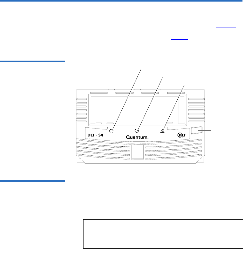
Chapter 13 Using the Tape Drive
Front Panel Controls and LEDs
DLT-S4 Product Manual 111
Front Panel Controls and LEDs 13
All controls and LEDs are on the tape drive’s front panel (see figure 43).
Use these controls and LEDs to operate the tape drive and monitor the
DLT-S4 tape drive system’s activities. See table 35 for a description of the
front panel controls and LED functionality.
Figure 43 Tape Drive Front
Panel
Left LED 13 On the DLT-S4 tape drive, the leftmost LED is dual color (green/orange).
This LED is the Density Indicator.
•Green — A DLTtape S4 cartridge is inserted
• Orange — A Backward Read Compatible (BRC) cartridge is inserted.
See table 35 for a summary of these combinations.
Note: The DLT-S4 tape drive is backward read compatible with
Super DLTtape II cartridges formatted in an SDLT 600 tape
drive; and Super DLTtape I cartridges formatted in an
SDLT 320 tape drive.
Eject button
Left LED
Middle LED
Right LED
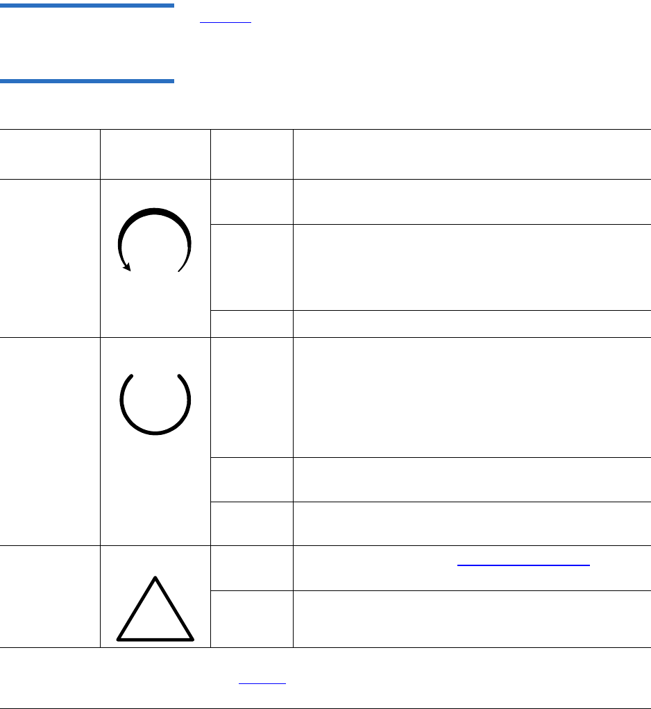
Chapter 13 Using the Tape Drive
Front Panel Controls and LEDs
DLT-S4 Product Manual 112
Front Panel Controls 13 Table 35 explains the function of the other LEDs and controls in the front
panel.
Table 35 Interpreting Front
Panel LEDs
LED/Button/
Port Title Color and
Symbol State or
Action Explanation
Left LED Green/Orange On
(Green)
Blank or formatted DLTtape S4 cartridge inserted
On
(Orange)
• SDLT 600 tape drive formatted Super DLTtape II
cartridge inserted
• SDLT 320 tape drive formatted Super DLTtape I
cartridge inserted
Off No compatible cartridge is inserted
Middle LED Green Flashing The tape drive is in use. This includes functions such as:
• The media is moving
• The tape drive is calibrating, reading, writing, or
rewinding the media
• The tape drive is loading, unloading, or rewinding
On The tape drive is idle. There may or may not be a
cartridge in the tape drive.
Off The tape drive has not been turned on or is not
connected to a power source.
Right LED Yellow On Cleaning is required. See Cleaning Instructions on
page 120 for cleaning instructions.
Off Cleaning is not required.
Notes: Whenever the tape drive resets, all LEDs illuminate briefly and then illuminate in sequence
until the reset completes (see table 36 on page 114 for a complete description).
Whenever the tape drive encounters an error, all LEDs flash together.
!

Chapter 13 Using the Tape Drive
Power-On Self-Test
DLT-S4 Product Manual 113
Power-On Self-Test 13
The DLT-S4 tape drive system performs a self-diagnostic test, called a
Power-On Self-Test (POST) each time you turn on the tape drive (see
table 36). This test helps in detecting problems with the tape drive.
POST completes in approximately 10 seconds. While POST is running,
the tape drive system responds BUSY to SCSI commands, but will
respond to various SCSI messages.
During POST, the tape drive responds in the following ways.
It may take longer than the duration of POST for the tape drive to become
ready.
Eject Button N/A Press Use the Eject button to eject the cartridge from the tape
drive. When you press the button, the tape drive
completes any active writing, then ejects the cartridge.
This button also “parks” the soft-load mechanism for
shipping. For instructions, see chapter 15, Preparing the
Tape Drive for Shipping.
See chapter 3, Cartridges for detailed cartridge
handling procedures.
If the host tries to negotiate... The tape drive...
synchronous transfer negotiates to asynchronous
wide transfer negotiates to narrow
LED/Button/
Port Title Color and
Symbol State or
Action Explanation
Notes: Whenever the tape drive resets, all LEDs illuminate briefly and then illuminate in sequence
until the reset completes (see table 36 on page 114 for a complete description).
Whenever the tape drive encounters an error, all LEDs flash together.

Chapter 13 Using the Tape Drive
Power-On Self-Test
DLT-S4 Product Manual 114
Table 36 LED Lighting Pattern
During POST
If the tape drive fails POST, check for the following possible problems:
• The tape drive is not receiving adequate power (try a new power
cable or a different outlet).
• The tape drive is not properly connected to the host computer and
other SCSI devices.
If any of these problems exist, correct the problem, turn off the tape drive,
and turn it back on to restart POST. For additional troubleshooting
guidelines, see POST and SCSI Troubleshooting on page 124.
Stage What You Observe
1
(Power cycle)
• All LEDs illuminate for approximately one
second.
2 • The left LED turns orange, then all LEDs turn off
simultaneously.
3 This stage typically lasts 5 to 10 seconds.
• The left and right LEDs remain off.
• The middle LED flashes until POST completes.
4When POST is complete:
• The middle LED stops flashing and remains
illuminated.
• The left and right LEDs remain off.
POST failure If POST fails:
• The middle and right LEDs illuminate steadily.
• The left LED flashes.
Note: If a cartridge is loaded when power is applied, all stages
remain the same except stage 3. It may take considerably
longer for stage 3 to complete because of media rewind and
searching operations that occur during this stage.

Chapter 13 Using the Tape Drive
Performing a Trial Backup
DLT-S4 Product Manual 115
Performing a Trial Backup 13
Complete the following steps to perform a trial backup and verify correct
tape drive installation:
1Insert a DLTtape S4 cartridge. Push the cartridge partially into the
system until the media automatically loads.
2Choose a sample file set from the host computer.
3Create a backup file and then restore the file set.
• If the backup file completely restores, without any errors, you
installed the system correctly.
• If you experience errors, double-check the tape drive’s
configuration and setup (see POST and SCSI Troubleshooting on
page 124).
After you have exhausted all troubleshooting alternatives, contact
your service representative.
4Press the Eject button to unload the cartridge (see figure 43 on
page 111).
Note: For specific instructions on loading cartridges, see chapter
3, Cartridges.

Chapter 13 Using the Tape Drive
Firmware Update via the Host Interface
DLT-S4 Product Manual 116
Firmware Update via the Host Interface 13
When you need to update the firmware in the tape drive, you can do it
either of two ways:
•Updating Firmware Using the Host Interface
•Creating a CUP/FUP Cartridge From Which to Update Firmware
(used in either a manual firmware update or in a library setting)
The xTalk Management Console tool allows you to update the tape
drive’s firmware using the host interface, or to create a CUP/FUP
cartridge for an DLT-S4 tape drive. See xTalk Management Console on
page 135 for information on downloading and using xTalk Management
Console.
The following subsections briefly describe both methods of updating the
tape drive firmware.
Updating Firmware Using
the Host Interface 13 Use xTalk Management Console to update the firmware:
1Follow the instructions for downloading xTalk Management Console
in xTalk Management Console on page 135.
2Follow the instructions in the xTalk Management Console User’s Guide
to download the firmware.
Creating a CUP/FUP
Cartridge From Which to
Update Firmware 13
Use xTalk Management Console to create a CUP/FUP cartridge:
1Follow the instructions for downloading xTalk Management Console
in xTalk Management Console on page 135.
2Follow the instructions in the xTalk Management Console User’s Guide
to create a CUP/FUP cartridge.
Follow these steps to use a CUP/FUP cartridge:
1Verify that the tape drive is turned on (power is applied), and the
middle LED on the front panel of the tape drive is on, but not
flashing.
2Verify that the tape drive’s cartridge opening is empty. If a cartridge
is in the tape drive, unload and eject it before proceeding.

Chapter 13 Using the Tape Drive
Firmware Update via the Host Interface
DLT-S4 Product Manual 117
3Press and hold the Eject button for six seconds; after six seconds, the
left LED begins to flash.
4Release the Eject button, then quickly press and release the Eject
button again.
At this point, the left and middle LEDs start flashing synchronously
in a regular, rhythmic pattern. The tape drive is now in Firmware
Upgrade mode.
You now have a “window” of 3 minutes to insert the CUP/FUP
cartridge. If you do not insert a CUP/FUP cartridge and the 3-minute
window expires:
• Both LEDs stop flashing, although the middle LED remains on
(steadily illuminated)
• The tape drive is now out of Firmware Update mode and can be
used in a normal manner (once you insert a cartridge)
To put the tape drive back in Firmware Update mode, repeat steps 2,
3, and 4.
5Insert the CUP/FUP cartridge.
After you insert the CUP/FUP cartridge, the left and middle LEDs
change their pattern and start flashing in an alternating pattern. The
tape drive is now performing the firmware update.
6Wait several minutes for the update process to complete.
The left and middle LEDs flash the entire time that firmware is being
updated.
When the update is complete, the tape drive resets itself and goes
through POST. The tape drive rewinds the CUP/FUP cartridge, then
Note: The firmware update fails the update process if the
firmware personalities do not match. The history log
(accessible via the LOG SENSE Page 07h) records this
information, as well as the reason for the failure.

Chapter 13 Using the Tape Drive
Firmware Update via the Library Tape Drive Interface
DLT-S4 Product Manual 118
unloads and ejects it. SCSI status indicates that firmware has been
updated (06h, 3F, 01).
Firmware Update via the Library Tape Drive Interface 13
The DLT-S4 library tape drive interface enables you to update the
firmware with a new version, or image via media update.
Follow these steps.
1Ensure that the tape drive contains no cartridge.
2Send the CODE UPDATE REQUEST command.
3Send the library ATTENTION command, then check the Tape Motion
Status field of the returned General Status Packet to verify the tape
drive is in the Ready for Code Update (0x09) state.
4Load the cartridge containing the new firmware into the tape drive.
5Send the library ATTENTION command, then check the Tape Motion
Status field of the returned General Status Packet to verify the
cartridge is loading (0x07).
6Send the library ATTENTION command, then check the Tape Motion
Status field of the returned General Status Packet to verify the
cartridge is in the CUP in Progress (0x0A) state.
7Send the library ATTENTION command, then check the Policy
Firmware Revision field to verify that the update completed
successfully.
Note: If the tape drive is mounted in a tape automation library,
the CUP/FUP cartridge rewinds to BOT and unbuckles in
preparation for unloading, but does not automatically
eject. Use the applicable library command to eject the
cartridge.
Note: It takes about 1 minute to enter the CUP in Progress (0x0A)
state.

Chapter 13 Using the Tape Drive
Cleaning the Tape Drive
DLT-S4 Product Manual 119
8Unload the cartridge and remove it from the tape drive.
Cleaning the Tape Drive 13
This section discusses the DLT-S4 tape drive cleaning cartridge,
maintenance considerations, and important compatibility issues.
When to Clean the Tape
Drive 13 Quantum tape drives occasionally require preventive cleaning. To a large
degree, the amount of ambient pollution and particulates in the
environment dictates the cleaning frequency.
Do not clean the tape drive unless the tape drive specifically indicates that
cleaning is necessary. When your backup software indicates that you need
to clean the tape drive, or the right (yellow) LED on the tape drive comes
on, use the cleaning cartridge to clean the unit. (See figure 43 on page 111
for the location of this LED.)
Which Cleaning Cartridge
to Use 13 Use ONLY the SDLT CleaningTape. Other cleaning cartridges, such as
CleaningTape III or DLT VS CleaningTape, are incompatible with the
DLT-S4 tape drive heads.
The cleaning cartridge is packaged in a plastic case, and is white in color.
Caution: During the firmware update, when reprogramming
the new image into the flash EEPROMs is actually in
progress, a power failure (but not bus RESET) or
power cycling the unit causes the controller module to
be unusable. When doing a firmware update, take
reasonable precautions to prevent a power failure.
Caution: Clean the tape drive only when the backup software or
right (yellow) LED light indicate cleaning is necessary (see
When to Clean the Tape Drive). Use only the correct
cleaning cartridge for your tape drive (see Which Cleaning
Cartridge to Use).

Chapter 13 Using the Tape Drive
Cleaning the Tape Drive
DLT-S4 Product Manual 120
Cleaning Cartridge Life
Expectancy 13 Each cleaning cartridge is good for 20 uses. Use one of the labels that is
supplied with the cleaning cartridge to track the number of uses and
discard the cleaning cartridge after the final use.
Cleaning Cartridge
Compatibility 13 The SDLT CleaningTape is compatible with SDLT 220, SDLT 320,
SDLT 600, and DLT-S4 tape drives.
Cleaning Instructions 13 To clean the tape drive, follow these steps:
1Insert a cleaning cartridge into the tape drive.
The middle (green) LED flashes and the cleaning cycle begins
automatically. Based upon previous cleaning cartridge usage, the
cleaning operation may last up to 10 minutes.
When the cleaning cycle completes, the tape drive automatically
ejects the cleaning cartridge; turns off the right LED; and steadily
illuminates the middle LED.
2Remove the cleaning cartridge, place it back in its plastic case, and
mark the label after each cleaning.
Note: To use the cleaning cartridge in an autoloader or library tape
drive, see the autoloader or library owner’s documentation.
Note: On the last (20th) cleaning, the tape drive does not eject the
cleaning cartridge. Press the Eject button on the front of the
tape drive to eject the expired cleaning cartridge. Dispose
of the expired cleaning cartridge.

Chapter 13 Using the Tape Drive
Optimizing Tape Drive Performance
DLT-S4 Product Manual 121
Cycle Time for Cleaning
Cartridge 13 Cycle times for cleaning cartridges are as follows.
On the last (20th) pass, the cleaning process completes and the cleaning
media is rewound, but the cleaning cartridge is not ejected. You must
manually eject the cartridge.
If the cleaning cartridge is loaded again after the 20th pass, it winds all
the way to the end of the cartridge and back again without performing
the cleaning sequence, and the cleaning cartridge does not eject. You
must manually eject the cartridge.
Optimizing Tape Drive Performance 13
Many factors contribute to tape drive performance. Host system
considerations include processor speed, block size, host adapter
performance, host bus configurations, and software.
If you are concerned about the performance of the tape drive, check the
following:
• Ensure that the tape drive is properly defined for the host system.
If the tape drive is not defined within the system, the host adapter
does not interact well with the tape drive.
• Ensure that the host bus adapter card and the SCSI bus are operating
in Ultra320 mode.
Cycle Time Valuea
a. These times are accurate to ± 20 seconds.
Shortest cycle time
(1st pass of cleaning cartridge)
2 minutes, 55 seconds
Longest cycle time
(20th pass of cleaning cartridge)
10 minutes, 20 seconds
“Expired” cycle time
(expired cleaning cartridge)
10 minutes
Chapter 13 Using the Tape Drive
Optimizing Tape Drive Performance
DLT-S4 Product Manual 122
• Check the host block size.
The DLT-S4 tape drive supports block sizes up to 16 MB. In general,
the larger the block size, the better the throughput. Many older
software applications default to a 512-byte block size, which results
in poor performance.
• Ensure that you are using a cartridge that is compatible with the tape
drive.

DLT-S4 Product Manual 123
Chapter 14
14Troubleshooting
This chapter lists troubleshooting tips and diagnostic tools to use if the
tape drive system fails or you experience poor performance. This chapter
covers:
•General Troubleshooting
•POST and SCSI Troubleshooting
•Over Temperature Condition
For complete inspection instructions for DLTtape S4, Super DLTtape II,
and Super DLTtape I cartridges, see chapter 3, Cartridges.
The Web site www.quantum.com also includes valuable information on
DLT systems.
General Troubleshooting 14
Follow these steps to troubleshoot problems with the DLT-S4 tape drive:
1Visually inspect the cartridge for damage, and try a new cartridge if
necessary (see chapter 3, Cartridges).
2Ensure that the cables and connectors are in good working condition.
For example, check that they are not worn or broken, and there are no
missing or bent pins.

Chapter 14 Troubleshooting
POST and SCSI Troubleshooting
DLT-S4 Product Manual 124
3Ensure that the connector on each end of the cable is fully seated.
4Disconnect the tape drive from the host system, turn off the tape
drive, and turn it on again to perform a POST (see Power-On Self-
Test on page 113).
5If you have a SCSI tape drive—remove all devices from the SCSI bus.
Connect the tape drive directly to the host computer and terminate it
(see Connecting the Cables and Terminating the SCSI Bus on page 74
for internal tape drives or Connecting the Tape Drive to the Host
Computer and Terminating the SCSI Bus on page 103 for tabletop
tape drives).
Confirm that the tape drive and host computer are communicating
properly before adding other devices.
6If you have a Fibre Channel tape drive—look at the rear panel to see
if the Fibre Channel cable is correctly attached (see Connecting the
Cables on page 86).
If the link light is illuminated, you have a working connection with
the Fibre Channel network.
7If you have a SAS tape drive -- look at the rear panel and make sure
the SAS cable is correctly attached (see Connecting the Cables on
page 95).
8Ensure that the operating system (modules, patches, and drivers),
backup software, and tape drive are compatible. See
www.quantum.com for the most current compatibility information.
If you cannot identify or correct the problem, contact customer support
(see Customer Support on page xviii for contact information). Have the
model and serial number available when you call. You can find these
numbers on the bottom of the tabletop tape drive enclosure and on the
top of the internal and library tape drives.
POST and SCSI Troubleshooting 14
Table 37 provides troubleshooting tips that you will find useful in the
event that the tape drive system fails its POST.

Chapter 14 Troubleshooting
POST and SCSI Troubleshooting
DLT-S4 Product Manual 125
If, after attempting the recommended actions listed in the table, the
problem still exists or recurs, a hardware failure may be the cause.
Contact your service representative.
Table 37 POST and SCSI
Troubleshooting Guidelines
If... Then... You should...
The computer does not
recognize the DLT-S4
tape drive system
The computer may not be
configured to recognize
the interface ID.
Configure the computer to recognize the DLT-S4
tape drive system’s ID.
The SCSI ID may not be
unique.
Change the SCSI ID and power cycle the entire
system.
The new ID becomes effective at the next power
cycle or interface bus reset.
Host bus adapter
parameters may be
incorrect.
• Check host bus adapter documentation for
parameter settings.
• Ensure that the host bus adapter card and the
SCSI bus are operating in Ultra320 mode.
The SCSI cable may be
loose.
Ensure the SCSI cable is fully seated at each
connector end.
The SCSI bus may not be
terminated correctly.
A terminator may not be at
the end of bus or more
than two terminators may
be present.
• Ensure that a terminator is installed at each end
of the bus (one terminator is usually already
installed at the host end of the bus).
• If the DLT-S4 tape drive is the last or only device
on the bus, be certain the terminator is installed
on the DLT-S4 tape drive.
• If the DLT-S4 tape drive is not the last or only
device on the bus, check the cable connections
and ensure that the bus is properly terminated at
each end.

Chapter 14 Troubleshooting
POST and SCSI Troubleshooting
DLT-S4 Product Manual 126
The computer does not
recognize the DLT-S4
tape drive system
(continued)
The SCSI bus may be too
long.
The maximum cable length for one DLT-S4 tape
drive is 20 meters. The maximum SCSI cable
interconnect length is 10 meters total with a
maximum of two DLT-S4 tape drives on the bus.
There may be too many
devices on the SCSI bus.
• Limit the number of tape drives on SCSI bus;
Quantum recommends one DLT-S4 tape drive
per bus, with a maximum of two DLT-S4 tape
drives per bus.
A device may not have
been turned on and a valid
SCSI ID may not have been
configured for that device
before the system powered
on and loaded BIOS.
Turn the tape drive on first, and then turn on the
computer. This will enable the tape drive to be
properly recognized by the system.
The tape drive does
not turn on
No power is reaching the
tape drive.
Check the tape drive’s power cable connection at
the rear of the system.
Nonfatal or fatal errors
have occurred for
which the cause
cannot be determined
Interface bus termination
or the interface cable
connections may be
incorrect.
• Ensure the SCSI bus is terminated and that all
connections are secure, or
• Ensure the Fibre Channel or SAS cables are
secured at the host and drive ends.
The AC power source
grounding may be
incorrect (tabletop model).
Use an AC outlet for the tabletop tape drive on the
same AC line used by the host system.
If... Then... You should...

Chapter 14 Troubleshooting
POST and SCSI Troubleshooting
DLT-S4 Product Manual 127
The tape drive is
operating more slowly
than indicated in its
performance
specification
Your host bus adapter may
be limiting the speed, or
you may be using an
incompatible cartridge.
• Check the host bus adapter documentation for
parameter settings.
• For the best performance, make sure the SCSI
controller card can operate at 320 MB/second.
Limit the number of tape drives on SCSI bus;
Quantum recommends one DLT-S4 tape drive
per bus, with a maximum of two DLT-S4 tape
drives per bus.
• Ensure that the tape drive is properly defined for
the host system. If the tape drive is not defined
within the system, the host adapter does not
interact well with the tape drive.
• Ensure that the host bus adapter card and the
SCSI bus are operating in Ultra320 mode.
• Check the host block size. The DLT-S4 tape drive
supports block sizes up to 16 MB. In general, the
larger the block size, the better the throughput.
Many older software applications default to a
512-byte block size, which results in poor
performance.
• Ensure that you are using a cartridge that is
compatible with the tape drive.
If... Then... You should...

Chapter 14 Troubleshooting
Over Temperature Condition
DLT-S4 Product Manual 128
Over Temperature Condition 14
The DLT-S4 tape drive has a thermal sensor located in the tape path. This
sensor, which is used to accurately monitor the air temperature in the
tape path, reacts in the following ways:
• TapeAlert occurs at 50 °C
• Shutdown occurs at 53 °C
SCSI status indicates the tape drive is in the over temperature condition.
For more information, see the DLT-S4 Product Specification (81-81279-xx)
and the DLT-S4 Interface Reference Guide (81-81281-xx).
Location
When the tape path temperature sensor
detects an over temperature condition
resulting in shutdown...
Not mounted in a
library
The media rewinds, unloads, and ejects from the
tape drive.
Mounted in a
library
The cartridge rewinds to BOT and unbuckles in
preparation for unloading, but does not
automatically eject.

DLT-S4 Product Manual 129
Chapter 15
15Preparing the Tape
Drive for Shipping
This chapter provides instructions on how to properly set the DLT-S4
tape drive for moving or shipping.
The DLT-S4 tape drive is equipped with a soft-load mechanism that is
“parked” prior to first power-on. Upon first power-on, the soft-load
mechanism becomes “un-parked” and ready for use.
If you intend to move or ship your DLT-S4 tape drive, you must “park”
the soft-load mechanism. (The soft-load mechanism will automatically
“unpark” upon the next power-on.)
1Remove the cartridge from the tape drive.
2Press and hold the Eject button for 15 seconds.
Midway through this 15-second interval, the left LED will flash
orange 5 times at a frequency of once per second. After the 15-second
interval, the left LED will flash green at a much higher frequency.
3Release the Eject button.
4Within 10 seconds, press and release the Eject button once.
The soft-load mechanism will “park” and the Left LED will flash
green at a frequency of once per second to verify the “parking”
operation is complete.
Caution: Do not ship the tape drive with a cartridge loaded
in it! This could cause damage to the tape drive or
the tape cartridge.
Chapter 15 Preparing the Tape Drive for Shipping
DLT-S4 Product Manual 130
5Power off the tape drive.
It is recommended that you retain and re-use the original packaging
materials if you plan to ship your DLT-S4 tape drive.

DLT-S4 Product Manual 131
Appendix A
ADiagnostic Tools
Quantum frequently provides new and updated tools to use with its tape
drives. These tools include such items as upgrades for product software
and firmware, and diagnostic software that may be newly developed.
These tools either come standard on the DLT-S4 firmware, or can be
downloaded from the Quantum Web site (see Accessing the Tools on
page 132 for instructions). New tools and utilities get added frequently,
so check the site often.
The tools discussed in this chapter are:
•Device Drivers
•TapeAlert
•Medium Auxiliary Memory
•DLTSage
•xTalk Management Console
•DLTSage Dashboard and DLTSage Tape Security

Appendix A Diagnostic Tools
Accessing the Tools
DLT-S4 Product Manual 132
Accessing the Tools 1
TapeAlert and Medium Auxiliary Memory are built-in features of the
DLT-S4 tape drive. The other tools described in this chapter can be
accessed from the Quantum Web site.
To access these tools:
1Go to the Quantum Web site: www.quantum.com.
2Click Service and Support in the upper menu bar. This opens the
Service and Support window.
3Click Downloads.
4Click the product for which you want to download (in this case,
DLT-S4 tape drive).
5Scroll down to the Downloads section to review the various items
until you find what you need.
Device Drivers 1
Quantum offers device drivers for:
•Windows
® 2000
•Windows XP
®
•Windows Server
TM 2003 (32-Bit Edition) - Intel x86 Platform
The Device Drivers allow for the use of all DLT tape drives with
Windows 2000, Windows XP, and Windows Server 2003 running on Intel
x86 (32-bit) platforms.
Note: These tools are only available to registered Quantum
customers.

Appendix A Diagnostic Tools
TapeAlert
DLT-S4 Product Manual 133
TapeAlert 1
DLT-S4 tape drives are delivered with TapeAlert features built in. The
tape drive firmware constantly monitors the device’s hardware and
media, checking for errors and potential difficulties. It flags any problems
identified on the SCSI LOG SENSE Page 2Eh.
After a backup, the TapeAlert-compatible backup application
automatically reads the device’s TapeAlert SCSI LOG SENSE Page 2Eh to
check for any problems. If an error is flagged, your backup software
displays a warning message on your screen, and adds the TapeAlert
messages to its logs. These messages are standard across all applications
that support TapeAlert, and give an explanation of the problem and
suggested resolution. For example, if you were attempting to back up to
an expired cartridge, you would see the following message:
WARNING: The data cartridge has reached the end of its calculated
useful life.
Copy any data you need to another cartridge.
Discard the old cartridge.
Medium Auxiliary Memory 1
Medium Auxiliary Memory (MAM) is a feature in the DLT-S4 tape drive
that produces various attributes about the cartridge and records them on
the media itself. These attributes provide the underlying information for
the DLTSage suite of intelligent data protection tools.
For more information on MAM, see the DLT-S4 Interface Reference Guide
(81-81281-xx).
You can view the MAM via xTalk Management Console (see xTalk
Management Console on page 135).

Appendix A Diagnostic Tools
DLTSage
DLT-S4 Product Manual 134
DLTSage 1
DLTSage is a suite of intelligent data protection tools that enables users to
more effectively manage and protect tape storage environments. Its
diagnostic and monitoring tools enhances manageability by allowing you
to manage and prevent problems that can occur during a routine backup.
DLTSage is a standard feature of the DLT-S4 tape drive, integrated as
part of the firmware. Some of the features of DLTSage are automatically
available to you when you use your backup software application. Others
(such as xTalk Management Console and DLTSage Dashboard) you must
download to use.
Several DLTSage applications are described in this manual:
•xTalk Management Console on page 135)
•DLTSage Dashboard and DLTSage Tape Security on page 136
•DLTSage WORM on page 34
The features of DLTSage are described in table 1. To learn more about
DLTSage and all its capabilities, see
http://www.dlttape.com/technology/DLTSage/index.aspx
Table 1 DLTSage Features
Feature Description
Manage The software ensures that you use tape drives and media as efficiently as possible.
• It provides management protocols for acquiring information on DLT tape drives
and media anywhere on an enterprise network
• It helps you to understand and control how tape drives are used throughout
your system
• It allows you to develop a complete inventory of tape drives and media and the
usage statistics for each
• You can ascertain which cartridges and which tape drives are nearing the end of
their useful lives.

Appendix A Diagnostic Tools
xTalk Management Console
DLT-S4 Product Manual 135
xTalk Management Console 1
xTalk Management Console is part of the DLTSage suite of tools. It allows
you to evaluate tape device health and determine when a device needs to
be sent for service or repair.
xTalk Management Console provides:
• Media and device diagnostic tools
• The ability to view analysis information
• The ability to quickly update the application or firmware
• The ability to create a secure DLTSage WORM tape (see Formatting a
Cartridge as DLTSage WORM on page 35)
See xTalk Management Console User’s Guide for detailed instructions on
how to use the software. The user’s guide is packaged with downloaded
software. For Windows users, access the user’s guide it through the Help
menu once the program is open (choose Help > Online User’s Guide).
Prevent The software allows you to see errors as they happen and correct them instantly.
• It alerts you to potential problems, enabling you to take corrective action
immediately
• It provides management protocol interfaces for third-party providers, such as
library and backup software vendors, to use key information across multiple
interfaces
• You can use tape drive and cartridge usage statistics to implement preventative
maintenance.
Feature Description

Appendix A Diagnostic Tools
DLTSage Dashboard and DLTSage Tape Security
DLT-S4 Product Manual 136
DLTSage Dashboard and DLTSage Tape Security 1
DLTSage Dashboard enables you to more effectively manage and protect
your tape storage environment. After you download DLTSage
Dashboard, it is accessible from the Windows Start menu and Device
Manager.
The Dashboard consists of the following two features:
•The
Status tab displays drive and media current health, status, and
security settings, including when the drive’s next cleaning is due and
the cartridge’s available free space.
•The
Tape Security tab allows you to add an electronic Secure Key to
tape cartridges. This protects your cartridges from unauthorized
access to data in the event that they are lost or stolen.
See the DLTSage Dashboard and DLTSage Tape Security Quick Start Guide
(81-81639-xx) for more information and instructions.

DLT-S4 Product Manual 137
Appendix B
BEnvironmental Compliance
This chapter describes the environmental compliance and provides basic
instructions for environmental disposal of your unit.
WEEE and RoHS Compliance 2
Quantum is committed to providing quality products in an
environmentally sound manner and to comply with all applicable
environmental laws, rules and regulations.
This product was designed, manufactured and made available with
consideration to worldwide laws, rules and regulations applicable to the
product and the electronics industry including the European Union
Directives 2002/95/EC & 2002/96/EC (RoHS and WEEE).

Appendix B Environmental Compliance
Disposal of Electrical and Electronic Equipment
DLT-S4 Product Manual 138
Disposal of Electrical and Electronic Equipment 2
This symbol on the product or on its packaging
indicates that this product should not be disposed of
with your other waste. Instead, it should be handed
over to a designated collection point for the recycling of
electrical and electronic equipment. The separate
collection and recycling of your waste equipment at the
time of disposal will help to conserve natural resources
and ensure that it is recycled in a manner that protects
human health and the environment. For more information about where
you can drop off your waste equipment for recycling, contact your local
government authority, your household waste disposal service or the
business from which you purchased the product.

DLT-S4 Product Manual 139
Appendix C
CRegulatory Statements
FCC Statement 3
This equipment has been tested and found to comply with the limits for a
Class A digital device, pursuant to Part 15 of the FCC Rules. These limits
are designed to provide reasonable protection against harmful
interference when the equipment is operated in a commercial
environment. This equipment generates, uses, and can radiate radio
frequency energy and, if not installed and used in accordance with the
instruction manual, may cause harmful interference to radio
communications.
Any changes or modifications made to this equipment may void the
user's authority to operate this equipment.
Operation of this equipment in a residential area may cause interference
in which case the user at his own expense will be required to take
whatever measures may be required to correct the interference.
This device complies with Part 15 of the FCC Rules. Operation is subject
to the following conditions:
1This device may not cause harmful interference, and
2This device must accept any interference received, including
interference that may cause undesired operation.
Appendix C Regulatory Statements
Taiwan Statement
DLT-S4 Product Manual 140
Taiwan Statement 3
Industry Canada (Digital Apparatus) 3
Reference: Interference-Causing Equipment Standard, ICES-003, Issue 2
This Class A digital apparatus meets all requirements of the Canadian
Interference-Causing Equipment Regulations.
Cet appareil numérique de la classe A respecte toutes les exigences du
Reglément sur le matériel brouilleur du Canada.
CISPR-22 Warning! 3This is a Class A product. In a domestic environment this product may
cause radio interference in which case the user may be required to take
adequate measures.
Achtung! 3Dieses ist ein Gerät der Funkstörgrenzwertklasse A. In Wohnbereichen
können bei Betrieb dieses Gerätes Rundfunkstörungen auftreten, in
welchen Fällen der Benutzer für entsprechende Gegenmassnahmen
verantwortlich ist.
Attention! 3Ceci est un produit de classe A. Dans un environment domestique, ce
produit peut causer des interférences radioélectriques. Il appartient alors
à l'utilisateur de prendre les mesures appropriées.
!" #$%&'()*+,-.

Appendix C Regulatory Statements
Notice for USA and CANADA Only
DLT-S4 Product Manual 141
Notice for USA and CANADA Only 3
If shipped to USA, use the UL LISTED power cord specified below for
100-120 V operation. If shipped to Canada, use the CSA CERTIFIED
power cord specified below for 100-120 V operation.
Plug Cap Parallel blade with ground pin (NEMA 5-15P configuration)
Cord Type: SJT, three 16 AWG (1.5 mm2) or
18 AWG (1.0 mm2) wires
Length Maximum 15 feet (4.5m)
Rating Minimum 10 A, 125 V
Attention 3LIRE LA REMARQUE DANS LE MODE D'EMPLOI.
Remarque 3CETTE REMARQUE NE CONCERNE QUE LES ÉTATS-UNIS ET LE
CANADA.
En cas d'envoi aux États-Unis, utiliser le cordon d'alimentation CERTIFIÉ
UL et convenant pour 100-120 V.
En cas d'envoi au Canada, utiliser le cordon d'alimentation CERTIFIÉ
CSA et convenant pour 100-120 V.
Fiche Broches parallèles avec une broche de mise à la terre
(configuration NEMA 5-15P)
Cordon Type: SJT, trifilaire 16 AWG (1.5 mm2) ou
18 AWG (1.0 mm2)
Longeur Maximum 15 pieds (4.5m)
Capacité Minimum 10 A, 125 V

Appendix C Regulatory Statements
Laser Statement
DLT-S4 Product Manual 142
Laser Statement 3
Class 1 Laser Product 3CAUTION: With all panels and enclosures in place, this product is rated
as a Class I laser product. The bar code scanner inside this product,
however, is a Class II laser. Avoid exposure to the laser light emitted from
the bar code scanner. Do not stare into the beam.
CAUTION: Use of controls or adjustments or performance of procedures
other than those specified herein may result in hazardous exposure.
Laser Klasse 1 3VORSICHT: Dieses Produkt Enthält Einen Laser der Kategorie II.
Laserstrahlen - Der Strichcode-scanner Gibt Laserstrahlen aus.
VERMEIDEN SIE jeden Blickkontakt und direkten körperlichen Kontakt
mit diesen Strahlen.
VORSICHT: Ein nicht ordnungsgemäßer (siehe hier enthaltene
Anweisungen) Einsatz bzw. Änderungen der Betriebsleistung können
einen Gesundheit gefährdenden Kontakt zur Folge haben.
Appareil à Laser de
Classe 1 3
ATTENTION: Ce produit émet de la classe laser II. Rayonnement laser -
NE PAS fixer des yeux le rayon. Éviter les expositions - Le rayonnement
laser est émis à partir du lecteur optique de code barre.
ATTENTION: L’utilisation de contrôles ou d’ajustements de
performance des procédures autres que ceux indiqués ici peut entraîner
une exposition dangereuse.
Producto Láser de
Clase 1 3
¡ATENCIÓN! Este producto contiene laser de clase II. Luz de laser - NO
mire el rayo. Evite el contacto con la luz: la luz de laser se emite desde el
explorador de código de barras.
¡ATENCIÓN! El uso de los controles o ajustes para realizar
procedimientos que no son especificados puede provocar una situación
peligrosa.
Appendix C Regulatory Statements
Power Cord Statement
DLT-S4 Product Manual 143
Luokan 1 Laserlaite 3ATTENZIONE: Questo prodotto emette una luce laser di Classe II. NON
guardare il facsio di luce ed evitare di esporsi alla fonte del laser. Il fascio
di luce laser h emesso dal dispositivo di scansione del codice a barre.
ATTENZIONE: L’uso di comandi o regolazioni per eseguire le procedure
che non siano quelli specificati in questa documentazione pur causare
rischi all ‘incolumit’ delle persone.
Power Cord Statement 3
DEN-AN Notice (Japan) 3

DLT-S4 Product Manual 144
Glossary
AAccess (v.) To read, write, or update information on a storage medium,
such as magnetic media. (n.) The operation of reading, writing, or
updating stored information.
Access Time The interval between the time a request for data is made by
the system and the time the data is available from the tape drive.
Advanced PRML Advanced Partial Response Maximum Likelihood. The
advanced PRML channel technology provides high-encoding efficiency
recording densities for greater capacity and performance.
AMP Media Advanced Metal Powder Media. A state-of-the-art media
first designed for Super DLTtape. It incorporates durable metal powder
technology for high-density data storage and embedded non-magnetic
information for head tracking.
Archiving The removal or copying of data from the computer system
onto secondary storage media that is safely stored away.
ASIC Application Specific Integrated Circuit.
BBackup A copy of a file, directory, or volume on a separate storage
device from the original, for the purpose of retrieval in case the original is
accidentally erased, damaged, or destroyed.
Base Plate An aluminum die casting that acts as the support platform
for the other modules and for the tape drive enclosure. The base plate

Glossary
DLT-S4 Product Manual 145
includes the precision mounting holes used to install SDLT tape drives
into a server or tape library.
Bezel (Also known as the faceplate.) A plastic panel that extends the face
of a tape drive so that it covers a computer’s tape drive bay opening. The
internal model of DLT-S4 has two bezels: a library bezel and an internal
bezel.
BIOS Basic Input/Output System. A set of routines that work closely
with the hardware to support the transfer of information between various
elements of the system, such as memory, disks, and peripheral devices.
Block A sector or group of sectors. DLT-S4 supports block sizes up to
16 MB.
BOT Beginning of Tape. The physical beginning of the media.
BRC Backward-read Compatibility is the ability of a current tape drive
product to read cartridges written on earlier model tape drives.
BSMI Bureau of Standards, Metrology, and Inspection (Taiwan).
Buckling Mechanism The buckling mechanism engages the media
leaders on cartridge load and disengages them on cartridge unload.
Buffer An area of RAM reserved for temporary storage of data that is
waiting to be sent to a device. The data is usually on its way to or from
the tape drive or some other peripheral device.
Bus The part of a chip, printed circuit board, or interface designed to
send and receive data.
CC The degree Celsius (°C) is a unit of temperature.
Cache Specialized RAM used as a buffer between a fast CPU or I/O
channel and storage which has a relatively slow access time (for example,
cartridge or diskette), to avoid slowing down the former.
CE Council of Europe.
Compressed Capacity Capacity after data has been processed, using
either software or hardware, to reduce storage space while maintaining
data integrity. (See also Data Compression.)
CFR Code of Federal Regulations (United States).
CSA Canadian Standards Association, also known as CSA International.
CTM Cartridge Tape Module. The main function of the SDLT’s CTM is to
provide the magnetic recording media used by the tape drive to store

Glossary
DLT-S4 Product Manual 146
customer information. The CTM also provides the protective cartridge,
which allows the media to be removed and stored safely.
CUP Code Update (a firmware update).
DData Compression A process that reduces the amount of storage space
required to hold a particular block of data. Data transfer speed and total
media capacity are affected by the data compression achieved. In
accordance with industry practice, a typical compression ratio is 2:1 of
data storage. Actual compression ratios achieved depend on the
redundancy of data files being written.
dB A Decibel is a logarithmic unit of sound intensity; 10 times the
logarithm of the ratio of the sound intensity to some reference intensity.
DC Direct Current is the continuous flow of electricity through a
conductor such as a wire from high to low potential.
DCB Drive Control Board.
Device According to the SCSI specification, multiple SCSI devices can be
connected to a single SCSI bus. Each SCSI device contains a SCSI ID
number that can be set in the range 0 to 15.
Device Driver A low-level (usually kernel-mode) operating system
component that enables a PC to communicate with peripheral devices
such as printers, CD-ROMs, and tape drives. Each kind of device requires
a different driver.
Differential A term referring to the electrical characteristics of the signal
used on the SCSI bus interface. Differential signals minimize the effect of
common mode signal noise and allow the SCSI bus to operate reliably
over greater distances at a higher speed.
DLT Digital Linear Tape.
DLTSage WORM Quantum’s firmware compliance management function
of DLTSage, which provides secure archival functionality to the DLT-S4
tape drive and the DLTtape S4 cartridge.
DLTSage Quantum’s suite of intelligent data protection tools that
enables users to more effectively manage and protect tape storage
environments.
DLZ Digital Lempel-Ziv 1 Algorithm is named after Abraham Lempel
and Jacob Ziv. It is a data compression technique used in all SDLT tape
drives.

Glossary
DLT-S4 Product Manual 147
EEEC European Economic Community.
EEPROM Electronically Erasable Programmable Read-Only Memory. An
integrated circuit memory chip that can store programs and data in a
non-volatile state. These devices store firmware in DLT and SDLT tape
drives, and can be erased and reprogrammed with new data.
EMC Electromagnetic Compatibility. The ability of a device or system to
function without error in its intended electromagnetic environment.
EMI Electromagnetic Interference. Electromagnetic emissions from a
device or system that interfere with the normal operation of another
device or system
EN EN standards are voluntary technical standards of the European
Union and European Economic Area.
Encoding (n.) Characters (or bytes) of information converted to magnetic
patterns on the media. (v.) The process of converting to the desired
pattern.
EOD End of Data. Location on media where the last session stopped.
EOM or EOT End of Media or End of Tape. Logical EOM allows space to
complete a write operation; physical EOM signifies that the media is
completely used.
Erase The removal of data from media.
Error A message that occurs when there is a loss of ability to interpret
recorded data; usually because of magnetic issues or defects in or on the
media.
ESD An Electrostatic Discharge is a sudden flow of electric current
through a material that is normally an insulator.
EU European Union.
FF Fahrenheit is a temperature scale where a degree Fahrenheit (°F) is 5/
9ths of a kelvin (or of a degree Celsius).
FC Fibre Channel
FCC Federal Communications Commission (United States).
Fibre Channel A high-speed serial architecture that allows either optical
or electrical connections at data rates from 265 MB to 2 Gb per second.
Fibre Channel is sometimes abbreviated FC.

Glossary
DLT-S4 Product Manual 148
Firmware Permanent or semi-permanent instructions and data
programmed directly into the circuitry of a programmable read-only
memory or electronically erasable programmable read-only memory
chips. Used for controlling the operation of the computer or tape drive.
Distinct from software, which is stored in random access memory and
can be altered with ease.
FUP Firmware Update.
GGB Gigabyte. Equal to 1,000,000,000 (109) bytes. This is the International
System of Units (SI) definition commonly used by telecommunications
and storage manufacturers.
Gb Gigabit. Equal to 1,000,000,000 (109) bits.
GS German Safety.
HHead The tiny electromagnetic coil and metal pole used to create and
read back the magnetic patterns on the media. Also known as the read/
write head.
IIEC The International Electrotechnical Commission is a standards
organization that prepares and publishes international standards for all
electrical, electronic, and related technologies.
Interface A hardware or software protocol—contained in the electronics
of the media controller and tape drive—that manages the exchange of
data between the tape drive and computer. The most common interfaces
for small computer systems are AT (IDE) and SCSI.
ISO The International Organization for Standardization is an
international non-governmental standard-setting body made up of
representatives from national standards bodies.
ISV Independent Software Vendor.
JJumper A tiny connector box that slips over two pins that protrude from
a circuit board. While in place, the jumper connects the pins electrically.
The jumper can be moved to change electrical connections.
KKB Kilobyte. Equal to 1,000 (103) bytes.
Kb Kilobit. Equal to 1000 (103) bits.

Glossary
DLT-S4 Product Manual 149
LLED Light Emitting Diode.
LGMR Laser Guided Magnetic Recording.
LVD Low Voltage Differential signalling is an electrical signalling system
that can run at high speeds.
MMAM Medium Auxiliary Memory (MAM) is an DLT-S4 tape drive
feature that provides information on the status and prior use history of an
SDLTtape III cartridge.
MB Megabyte. Equal to 1,000,000 (106) bytes. This is the International
System of Units (SI) definition used by telecommunications engineers
and storage manufacturers.
MDB Motor Driver Board
MR Magneto Resistive.
MRC Heads Magneto Resistive Cluster Heads. A cluster of small, cost-
effective Magneto Resistive (MR) media heads packed densely together.
ms A Millisecond is equal to one thousandth of a second.
NNative Capacity The capacity of a given media product in its basic
recording format (without the use of data compression).
Native Mode Refers to the uncompressed storage capacity of a media
subsystem. (See Native Capacity.)
Node In referring to a Fibre Channel network, a node is any device
attached to the network.
PPAB Pre-amplifier Board
Parity A method of generating redundant information that can be used
to detect errors in stored or transmitted data.
PCBA Printed Circuit Board Assembly
Peripheral A device added to a system as a complement to the basic
central processing unit (CPU), such as a disk drive, tape drive, or printer.
Port In referring to a Fibre Channel network, a port connects a node to
the network.

Glossary
DLT-S4 Product Manual 150
Positive Engagement Buckling Mechanism A highly robust, solidly
engineered media leader-buckling mechanism for heavy-duty-cycle
automated environments.
POST Power-on Self-Test. When power is applied to the tape drive, it
performs a POST.
Power Cycle The act of turning the tape drive or system off, then on
again.
PRML Partial Response Maximum Likelihood is a method for converting
the weak analog signal from the head of a magnetic disk drive into a
digital signal. Also see Advanced PRML.
PWA Printed Wiring Assembly.
RReceiver (cartridge) At media insertion, the cartridge receiver assembly
is responsible for guiding the media into its operating position, opening
the door, unlocking the cartridge brakes, and securing the media for
operation. At media ejection, the cartridge receiver assembly reverses the
process and automatically ejects the cartridge a fixed distance from the
front of the tape drive.
Restore To replace data on the hard drive with data obtained from
another media device.
RoHS Restrictions on Hazardous Substances is an EU directive that
restricts, and in some cases bans, the use of certain compounds in the
manufacture of electronic equipment. RoHS mandates that new electrical
and electronic equipment put on the market does not contain lead,
mercury, cadmium, hexavalent chromium, poly-brominated biphenyls
(PBB), or poly-brominated diphenyl ethers (PBDE).
SSAS Serial Attached SCSI.
SCSI Small Computer System Interface. An American National
Standards Institute (ANSI) standard for the interface between a computer
and peripheral controllers.
SDLT Super Digital Linear Tape.
Seek The movement of a read/write head to a specific data track.
Server A powerful computer system with a large tape drive capacity
that serves the information access and communication needs of multiple
users.

Glossary
DLT-S4 Product Manual 151
Shelf Life The length of time that media can be stored without losing its
magnetic strength. For Super DLTtape II media, this period is 30 years or
more.
SI The International System of Units.
TTB Terabyte. Equal to 1,000,000,000,000 (1012) bytes. This is the
International System of Units (SI) definition used by telecommunications
engineers and storage manufacturers.
Take-up Reel The reel inside every tape drive onto which DLTtape or
Super DLTtape media is wound. The in-the-tape drive take-up reel
enables DLTtape and Super DLTtape systems to operate using a single-
reel cartridge and thereby pack more media and data into every
cartridge.
TapeAlert™ A firmware feature that monitors and returns the results of
the tape drive’s on-going self-diagnosis activity.
Tape Path The path through which media moves from the cartridge, past
the read/write head, and onto the take-up reel.
Termination A physical requirement of the SCSI bus. A terminator is a
device that attaches to both ends of an electrical bus and prevents
reflection or echoes of signals that reach the end of the bus.
Track A linear or angled pattern of data written on a media surface.
SDLT tape drives write information on multiple tracks simultaneously.
Transfer Rate The speed at which the data moves between a host (that is,
tape drive) and a recorded device. Usually expressed as bytes/sec or
bits/sec.
UUL Underwriters Laboratories is a testing laboratory, which develops
standards for consumer products, chiefly dealing with product safety.
Unformatted Capacity The total number of usable byes on the media,
including the space that will be required later to record location,
boundary definitions, and timing information. (See also Native Capacity.)
Ultra320 An DLT-S4 tape drive SCSI interface that provides a low-
voltage differential (LVD) mode running up to 160 MB/sec.
USB Universal Serial Bus is a serial bus standard for connecting devices
to a computer.

Glossary
DLT-S4 Product Manual 152
VV A Volt is the potential difference across a conductor when a current of
one ampere dissipates one watt of power.
VCCI Voluntary Control Council for Interference by Information
Technology Equipment (Japan).
WW The Watt is the SI derived unit of power.
WEEE Waste Electronic and Electrical Equipment is an EU directive that
mandates that producers of electronic goods assume the responsibility of
recycling WEEE and create sustainable development programs to design
more easily reusable and recyclable products.
WORM Write Once Read Many is a functionality, which provides secure
archived records needed for government compliance.

DLT-S4 Product Manual 153
Index
Numerics
10-pin connector (see loader/library
interface connector)
12-pin connector (see SCSI > ID,
setting)
4-pin connector (see power
connector pin assignments)
68-pin connector (see SCSI >
connectors)
A
access door, media 24, 27 – 28
access time 6
acoustic noise emissions 42
AC power 14, 41, 105 – 106
cable 105 – 106
AC power supply tests 41
actuator driver 9
actuator sensor 9
additional devices, adding
Fibre Channel 88
SAS 97
SCSI (internal model) 78 – 79
tabletop tape drive 107 – 109
advanced metal powder media 7
advanced partial response
maximum likelihood 7, 9
advanced PRML 7, 9
air flow 9, 38
arbitrated loop configuration 61
asynchronous transfer 11, 113
Australian regulations 40
auto load 8
B
backup data 115
backward compatibility 4, 20, 22,
111
backward-read compatible
transfer rates 22
base mechanical assembly 8, 10
base plate 8
beginning of tape (BOT) access
time 6
bezel 9, 10, 111
bezel controls (see front panel
controls, LEDs)
board assemblies 9, 10
buckling clips 28
buckling mechanism 7, 28
burst (maximum) 5
C
cables
(see also connectors)
AC power 105 – 106
Fibre Channel 56 – 57, 58
connection of 86 – 87
hot swappable 58, 64
length of 50, 126
SAS 64
connection of 95 – 96

Index
DLT-S4 Product Manual 154
SCSI 49 – 50
connection of (internal tape
drive) 74 – 76
connection of (tabletop tape
drive) 103 – 106
Canada
regulations 40
cartridge
(see also cleaning cartridge,
media)
cleaning (see cleaning cartridge)
code update 116
compatibility 19 – 20
CUP/FUP 116
DLTSage WORM 34 – 36
dropping 29
ejecting 113
firmware update 116
handling 23 – 25
humidity 24 – 25
inspection 25 – 29
labeling 24
loading 32 – 33
media access door 24, 27 – 28
physical characteristics 20
reel lock 26 – 27
storage 23 – 25
temperature 24 – 25
unloading 33 – 34
unsupported, use of 21
WORM 34 – 36
write once, read many 34 – 36
write-protecting 29 – 31
cleaning cartridge
compatibility 120
cycle time 121
instructions for use 120
life expectancy 120
which type to use 119
cleaning the tape drive 119 – 121
code update (see firmware update)
compatibility
(see also backward
compatibility)
back-up software 18
backward 4, 20, 22, 111
cartridge 19 – 20
operating system 18
components of the tape drive 8 –
10
compressed
capacity 4
storage capacity 2
transfer rates 2, 5, 6
compression ratio 2
conducted electromagnetic
emissions 41
configuration (see installation)
connectors
(see also cables, rear panel
connectors)
common interface 46 – 47
daisy-chain 107
Fibre Channel 56, 56 – 57
loader/library interface 46 –
47
pin assignments (see pin
assignments)
rear panel 46 – 47
SAS 63, 64, 91
SCSI 49, 49 – 50, 51, 68
tabletop tape drive 100
contact Quantum xvii
control boards 9
CUP/FUP cartridge 116
current harmonics emissions 41
customer support xviii
D
data backup 115
data transfer rates 5
density
linear bit 6
track 6
depth, tape drive 39
device drivers 132
diagnostic tools 131 – 136
dimensions, tape drive 39
disposal of equipment 138
DLT-S4 tape drive (see tape drive)
DLTSage
Dashboard 136
general description 134
Tape Security 136
WORM 34 – 36
drive control board (DCB) 10
drivers 9, 132
dust door 9
E
eject button 9, 113
EJECT command 21
ejecting a cartridge 113
electrical rating 38
electromagnetic emissions 41
electromagnetic interference (see
EMI)
electronic signature key 34
electrostatic discharge (see ESD)

Index
DLT-S4 Product Manual 155
EMI
certification 40
and immunity 41
specifications 40 – 41
emissions 40 – 41
environmental compliance 137 –
138
error frequency 38
errors 135
ESD 15
precautions 16 – 17
European regulations 40
F
FCC regulations 40
Fibre Channel tape drive
cables 56 – 57, 58
connection of 86 – 87
connectors 56 – 57
installation 80 – 88
interface 12, 55 – 61
loop address, failure to
obtain 58
loop configuration 55
power usage 58
protocol options 11
rear panel connectors 56, 82
shipping 83
speed 5, 11, 57, 59 – 60
speed negotiation 57, 59 – 60
topology 59 – 61
topology negotiation 57, 59 –
61
transfer rates 5
unpacking 83
firmware
DLTSage WORM 34
TapeAlert 133
firmware update
cartridge (CUP/FUP) 116
via the library 118
via the SCSI bus 116
flicker emissions 41
form factor 4
front panel assembly (see bezel)
front panel controls
(see also LEDs)
eject button 113
general description 111
lighting pattern 114
front panel module, (see bezel)
G
glossary 144
H
hall sensors 9
handling guidelines
cartridge 23 – 25
tape drive 15 – 16
harmonic emissions 41
height, tape drive 39
host interface 11
hot-swappable cables 58, 64
humidity
cartridge 24 – 25
tape drive 16, 38, 101
I
idle mode 42, 112
immunity
and EMI 41
specifications 41
tests 41
inspection
cartridge 25 – 29
shipping box 17 – 18
tape drive 17 – 18
installation
(see also cables)
Fibre Channel tape drive 80 –
88
pre-installation guidelines 17
SAS tape drive 89 – 97
SCSI tape drive (internal) 66 –
79
tabletop tape drive 98 – 109
interface
physical characteristics 12
protocol options 11
speeds 11
types 4
internal tape drive
(see also items listed individually
under SCSI tape drive
(internal model), Fibre
Channel tape drive, and SAS
tape drive)
dimensions and weights 39
illustration of 3
J
Japan regulation 40

Index
DLT-S4 Product Manual 156
L
laser guided magnetic
recording 7
laser information 15, 142
leader
media 7, 8, 24, 27, 29
tape drive 7
leader bar 28
LEDs 9
(see also front panel controls)
during firmware update 116
during POST 114
during tape load 32
during tape unload 33
general description 111
left LED 21, 111, 112
lighting pattern 112
middle LED 112
right LED 112
tape drive errors 112
left LED 21, 111, 112
library tape drive xiii, 2
connectors 49, 56, 63
dimensions and weights 39
loader connectors 47
linear bit density 6
loader/library interface
connector 46 – 47, 79, 88, 97
loading a cartridge 32 – 33
load time 6
logical tracks 6
loop configuration 55
LVD
Ultra320 interface 11
M
magneto resistive cluster heads 7
MAM 133
media
(see also cartridge)
access door 24, 27 – 28
advanced metal powder 7
description 4
leader 7, 8, 24, 27, 29
speed 6
tension 6
medium auxiliary memory 133
memory update (see firmware
update)
middle LED 112
Mode 51
model number 17 – 18
motor driver board (MDB) 9, 10
motor drivers 9
mounting holes 72 – 73, 84 – 85,
93 – 94
MSE LVD mode SCSI connector pin
assignments 53
MSE mode SCSI connector pin
assignments 51
N
narrow transfer 113
native
backward-read compatibility
transfer rate 22
capacity 4
storage capacity 2, 22
transfer rates 2, 5, 6
New Zealand regulations 40
noise power emissions 42
O
over temperature condition 128
P
packing materials
saving 17, 69, 83, 92, 101
parking the soft-load
mechanism 113, 129
partial response maximum
likelihood (PRML) 7
performance
optimizing 121
troubleshooting 121, 127
physical interface 12
physical tracks 6
pin assignments
loader/library interface
connector 46 – 47
power connector 46
SCSI MSE LVD mode 53
SCSI MSE mode 51
point-to-point configuration 61
power, AC 14, 41
power cables 105 – 106
tabletop tape drive 105
types 106
power connector pin
assignments 46
power-on self-test (POST)
general description 113
troubleshooting 114, 124
power usage

Index
DLT-S4 Product Manual 157
Fibre Channel tape drive 58
SAS tape drive 65
pre-amplifier board (PAB) 9, 10
pre-installation guidelines 17 –
18
PRML 7
protocol options
Fibre Channel tape drive 11
SAS tape drive 11
SCSI tape drive 11
Q
Quantum
customer support xviii
R
radiated electromagnetic
emissions 41
rear panel connectors
all models 46 – 47
Fibre Channel tape drive 56,
82
SAS tape drive 63, 91
SCSI tape drive (internal) 49,
68
tabletop tape drive 100
reel drivers 9
reel lock 26 – 27
Related documents xvi
reset
SCSI bus 125
SCSI ID 69
tape drive 58, 112, 117
rewind speed 6
rewind time 6
right LED 112
RoHS compliance 137
S
safety
certifications 38
of data 23
precautions 14 – 15
SAS tape drive
cable 64
cables, connection of 95 – 96
connector 64
installing 89 – 97
interface 12, 62 – 65
protocol options 11
rear panel connectors 63, 91
shipping 92
speed 5, 11, 64, 65
speed negotiation 64, 65
transfer rates 5
unpacking 92
SCSI
(see also SCSI tape drive,
tabletop tape drive)
cable lengths 50
cables 49 – 50
commands
firmware update 118
timeout lengths 44
connectors 49 – 50, 51
ID, setting 69 – 71, 102 – 103
interface 12, 48 – 54
pin assignments 51
stub lengths 50
TapeAlert 133
troubleshooting 125
SCSI tape drive
protocol options 11
speed 5, 11
transfer rates 5
SCSI tape drive (internal model)
(see also SCSI)
cables, connecting 74 – 76
connectors 49, 68
installation 66 – 79
rear panel connectors 49, 68
SCSI ID setting 69 – 71
shipping 69
termination 74 – 76
TERMPWR, setting 77
unpacking 69
SCSI tape drive (tabletop model)
(see tabletop tape drive)
SDLT 320
BRC transfer rates 22
SDLT 600
BRC transfer rates 22
search speed 6
security (see DLTSage WORM,
DLTSage Dashboard, and
DLTSage Tape Security)
selftests (see POST)
serial number 17 – 18
serial port 46 – 47
shipping
box 17
preparing drive for 129 – 130
weight 39
signature key 34
soft-load mechanism 8
parking 113, 129
unparking 129

Index
DLT-S4 Product Manual 158
sound pressure emissions 42
specifications
interface 43 – 47
tape drive 37 – 42
speed 5, 11, 12, 57, 59 – 60, 64
(see also transfer rates)
Fibre Channel tape drive 5,
11, 12, 57, 59 – 60
linear search 6
maximum burst 5, 11
read/write 6
rewind 6
SAS tape drive 5, 11, 12, 64,
65
SCSI tape drive 5, 11, 12
speed negotiation
Fibre Channel 59 – 60
Fibre Channel tape drive 57
SAS tape drive 64, 65
status, of tape drive and cartridge
(see DLTSage Dashboard)
storage capacity 2, 4
storage guidelines
cartridge 23 – 25
tape drive 15 – 16
storage management software 35
streaming mode 42
stub lengths 50
synchronous transfer 113
T
tabletop tape drive
(see also SCSI)
AC power 105
cables, connection 103 – 106
configuration 109
dimensions and weights 39
illustration of 3
installation 98 – 109
pre-installation guidelines 17
rear panel connectors 100
SCSI ID setting 102 – 103
shipping 101
termination 103 – 106, 109
TERMPWR 109
unpacking 101 – 102
Taiwan
regulations 40
TapeAlert
feature 133
over temperature
condition 128
tape drive
(see also items listed individually
under SCSI tape drive
(internal model), Fibre
Channel tape drive, SAS tape
drive, and tabletop tape
drive)
appearance 2 – 3
cleaning 119 – 121
components 8 – 10
design 8
internal model 3
library model 2
performance 121
storage capacity 4
tabletop model 3
tape drive leader 7
tape heads 7
cleaning 119
tape leader (see media leader)
tape leader buckling
mechanism 7, 28
temperature
acclimitization 69, 83, 92, 101
cartridge 24 – 25
tape drive 38
tension 6
termination
SCSI tape drive (internal
model) 74 – 76
tabletop tape drive 103 – 106,
109
troubleshooting 125
terminator (see termination)
terminator power, setting 77, 109
TERMPWR
internal SCSI tape drive 77
tabletop tape drive 109
tools, diagnostic 131 – 136
topoloby
Fibre Channel tape drive 12
topology
Fibre Channel 59 – 61
Fibre Channel tape drive 57
SAS tape drive 12
topology negotiation
Fibre Channel 59 – 61
Fibre Channel tape drive 57
track density 6
transfer rates 2, 5, 6, 22
(see also speed)
backward-read compatible 22
Fibre Channel tape drive 5
SAS tape drive 5
SCSI tape drive 5
trial backup 115
troubleshooting 123 – 128
cartridges 25 – 29
over temperature
condition 128
tape drive 123

Index
DLT-S4 Product Manual 159
tape drive performance 121
U
Ultra320 11
United States regulations 40
unloading a cartridge 33 – 34
unload time 6
unpacking the tape drive
Fibre Channel 83
SAS 92
SCSI (internal) 69
tabletop 101 – 102
unparking the soft-load
mechanism 129
updating firmware 116, 118
W
warranty information 14, 17
(see also www.quantum.com)
WEEE compliance 137
weight, tape drive 39
wide transfer 113
width, tape drive 39
Windows device drivers 132
world-wide names
Fibre Channel tape drive 61
SAS tape drive 65
WORM cartridges, formatting,
DLTSage WORM 34 – 36
write driver 9
write-once read-many
(WORM) 34 – 36
write-protecting 29 – 31
write-protect tab 29, 29 – 31
