Quantum Scalar 50 Users Guide User’s
Tape Library PX502 81-81768-02_A01
2015-07-28
: Quantum Quantum-Scalar-50-Users-Guide-780315 quantum-scalar-50-users-guide-780315 quantum pdf
Open the PDF directly: View PDF ![]() .
.
Page Count: 290 [warning: Documents this large are best viewed by clicking the View PDF Link!]
- Contents
- Figures
- Tables
- Preface
- Library Description
- Basic Library Operations
- Quantum Scalar 50 Remote Management
- SNMP Trap List
- Troubleshooting
- Specifications
- SDLTtape Cartridge Maintenance
- Installing the Scalar 50 Library
- Repacking the Scalar 50 Library
- Firmware Upgrade Instructions for Stacked Libraries
- Regulatory Statements
- Glossary
- Index

Quantum Scalar 50
81-81768-02 A01
Quantum Scalar 50
Scalar Series
User’s Guide User’s Guide User’s Guide User’s Guide User’s Guide
Quantum Scalar 50 User’s Guide, 81-81768-02 A01, July 2008, Made in USA.
Quantum Corporation provides this publication “as is” without warranty of any kind, either express or
implied, including but not limited to the implied warranties of merchantability or fitness for a particular
purpose. Quantum Corporation may revise this publication from time to time without notice.
COPYRIGHT STATEMENT
Copyright 2008 by Quantum Corporation. All rights reserved.
Your right to copy this manual is limited by copyright law. Making copies or adaptations without prior
written authorization of Quantum Corporation is prohibited by law and constitutes a punishable violation of
the law.
TRADEMARK STATEMENT
DLT, SDLT, DLTtape III, DLTtape IV and Super DLTtape I are all trademarks of Quantum Corporation.
Other trademarks may be mentioned herein which belong to other companies.

Quantum Scalar 50 User’s Guide iii
Contents
Preface xvii
StorageCare Guardian...................................................................................xxii
Chapter 1 Library Description 1
Overview............................................................................................................. 2
Tape Drives......................................................................................................... 5
Tape Drive Types........................................................................................ 5
Library Features................................................................................................. 8
Front Panel................................................................................................... 8
Internal Layout.......................................................................................... 10
Back Panel.................................................................................................. 11
DLTSage™ Tape Security............................................................................... 13
Mixed Media Support ..................................................................................... 13
Capacity on Demand....................................................................................... 13
Enabling Capacity on Demand............................................................... 14
Library Scalability (Stacked Configurations)............................................... 15
Multiple Library Stack Requirements ................................................... 15
Getting Started ................................................................................................. 18
Installing the Quantum Scalar 50........................................................... 18
Cabling the Quantum Scalar 50 Series .................................................. 19
Loading Tape Cartridges......................................................................... 20
Initial Configuration................................................................................. 20

Contents
Quantum Scalar 50 User’s Guide iv
Chapter 2 Basic Library Operations 21
Installing Tape Cartridges .............................................................................. 21
Taking ESD Precautions .......................................................................... 23
SDLT Cartridges ....................................................................................... 24
LTO Cartridges ......................................................................................... 26
Cleaning Cartridges.................................................................................. 28
Preparing the Library for Operation............................................................. 30
Close the Cabinet Doors and Access Panels ......................................... 30
Connecting to Host Workstations .......................................................... 31
Turning the Library On and Off .................................................................... 36
Turning On the Library............................................................................ 36
Turning Off the Library ........................................................................... 37
Placing the Library On-line or Off-line.................................................. 37
Using the OCP.................................................................................................. 37
Home Screen.............................................................................................. 37
OCP Buttons .............................................................................................. 38
OCP Components ............................................................................................ 38
Info Screen ................................................................................................. 40
Operations Screen..................................................................................... 45
Setup Screen............................................................................................... 50
Diags Screen .............................................................................................. 57
Load Port Configuration................................................................................. 60
Chapter 3 Quantum Scalar 50 Remote Management 63
Quantum Scalar 50 Web Pages ...................................................................... 64
Quantum Scalar Web Page Menu Items................................................ 64
Accessing Scalar 50 Web Pages............................................................... 67
Using the Quantum Scalar 50 Web Pages............................................. 67
Quick Status............................................................................................... 68
Status.................................................................................................................. 70
Overview Page .......................................................................................... 70
Hardware Status Page.............................................................................. 71
Event Log Page.......................................................................................... 72
Statistics Page ............................................................................................ 73
Operations......................................................................................................... 77
Accessing the Operations Page............................................................... 77
Find Page.................................................................................................... 78
Move Page.................................................................................................. 80
Inventory Page .......................................................................................... 82
Drives Page................................................................................................ 83

Contents
Quantum Scalar 50 User’s Guide v
Setup .................................................................................................................. 84
Accessing the Setup Page ........................................................................ 85
Identification.............................................................................................. 86
Users ........................................................................................................... 87
Key Users ................................................................................................... 88
SCSI/Fibre ................................................................................................. 91
iSCSI Bridge............................................................................................... 92
Network ..................................................................................................... 93
Events ......................................................................................................... 95
Date & Time............................................................................................... 99
Library...................................................................................................... 101
Partitions .................................................................................................. 102
Field Service............................................................................................. 108
Setup Wizard........................................................................................... 108
Secure Key....................................................................................................... 113
Protection Mode for Cartridges............................................................ 115
Enable/Disable Secure Key for Drives................................................ 116
Select Secure Key for Library................................................................ 117
Assign Secure Key to Cartridge............................................................ 117
Create Secure Key Name/Secure Key Pair......................................... 118
Delete Secure Key Name ....................................................................... 119
Backup Secure Key File.......................................................................... 120
Upload Secure Key File.......................................................................... 121
Secure Key Best Practices and Tape Migration ......................................... 122
Best Practices ........................................................................................... 122
Key Migration Scenarios........................................................................ 122
Utilities ............................................................................................................ 124
Library...................................................................................................... 125
System Tests ............................................................................................ 127
Maintenance ............................................................................................ 129
Logs........................................................................................................... 131
Tasks ......................................................................................................... 133
Reference ......................................................................................................... 134
Logout.............................................................................................................. 136
Chapter 4 SNMP Trap List 137
Chapter 5 Troubleshooting 164
Common Problems and Solutions............................................................... 164

Contents
Quantum Scalar 50 User’s Guide vi
Start-up Problems ................................................................................... 165
OCP Problems ......................................................................................... 166
Robotics (Hand) Problems..................................................................... 166
Operating Problems ............................................................................... 168
Interpreting System LED Status .................................................................. 170
Operator Control Panel (OCP) LED Status......................................... 171
System Controller Board (SCB) LED Status........................................ 171
Power Supply LED Status ..................................................................... 175
Tape Drive LED Status........................................................................... 176
Appendix A Specifications 177
Physical Specifications .................................................................................. 178
Performance Specifications........................................................................... 179
Reliability Specifications............................................................................... 180
Tape Drive Specifications ............................................................................. 180
Environmental Specifications....................................................................... 181
Noise Levels............................................................................................. 181
SCSI Specifications......................................................................................... 181
Appendix B SDLTtape Cartridge Maintenance 182
Handling DLTtape Cartridges..................................................................... 182
Visual Inspection of DLTtape Cartridges................................................... 183
When To Visually Inspect a DLTtape Cartridge................................ 183
Visual Inspection Procedure ................................................................. 183
Appendix C Installing the Scalar 50 Library 187
Selecting an Installation Location................................................................ 187
Rack Space Requirements...................................................................... 188
Environmental Conditions.................................................................... 189
Preparing for the Installation ....................................................................... 189
Providing Necessary Tools and Equipment ....................................... 189
Taking ESD Precautions ........................................................................ 189
Installing the Library..................................................................................... 190
Locating the Mounting Position ........................................................... 190
Installing the Library.............................................................................. 192
Loading the Tape Cartridges ................................................................ 207

Contents
Quantum Scalar 50 User’s Guide vii
Initial Configuration............................................................................... 207
Emergency Library Access ........................................................................... 213
Appendix D Repacking the Scalar 50 Library 216
Removing the Library from the Rack.......................................................... 217
Installing the Internal Shipping Restraints ................................................ 220
Packing the Library for Shipment ............................................................... 224
Appendix E Firmware Upgrade Instructions for Stacked Libraries 226
Changing the Library Stack Role................................................................. 227
Uploading Library Firmware....................................................................... 228
Returning the Library Stack Role ................................................................ 233
Appendix F Regulatory Statements 235
Laser Statement.......................................................................................238
Glossary 259
Index 261

Quantum Scalar 50 User’s Guide viii
Figures
Figure 1 Scalar 50......................................................................................... 2
Figure 2 Slot Numbering, Scalar 50 SDLT ............................................... 3
Figure 3 Slot Numbering, Scalar 50 LTO.................................................. 4
Figure 4 Scalar 50 Front Panel.................................................................... 8
Figure 5 Scalar 50 Internal Layout .......................................................... 10
Figure 6 Scalar 50 Back Panel................................................................... 12
Figure 7 Multiple Library Stack (Cross Section..................................... 16
Figure 8 Rack Space Requirements......................................................... 19
Figure 9 Connecting the Library to the Local Area Network ............. 20
Figure 10 Inserting a Barcode Label (SDLT)............................................ 25
Figure 11 SDLT Cartridges......................................................................... 26
Figure 12 LTO Cartridges........................................................................... 28
Figure 13 SDLT Cleaning Cartridges........................................................ 29
Figure 14 LTO Cleaning Cartridges.......................................................... 29
Figure 15 Closing the Scalar 50 Front Doors............................................ 30
Figure 16 Scalar 50 Cable Configuration (SCSI Full Height Drives).... 32
Figure 17 Scalar 50 Cable Configuration (Native Fibre Channel Full
Height Drives) ............................................................................ 32
Figures
Quantum Scalar 50 User’s Guide ix
Figure 18 Scalar 50 Cable Configuration (SCSI Half-Height Drives)... 33
Figure 19 Scalar 50 Cable Configuration (SAS Half-Height Drives).... 33
Figure 20 Scalar 50 Cable Configuration (Native Fibre Channel Half-
Height Drives)............................................................................. 34
Figure 21 Scalar 50 Cable Configuration (Stacked)................................. 35
Figure 22 Turning On the Library ............................................................. 36
Figure 23 OCP Home Screen...................................................................... 38
Figure 24 OCP Component Tree................................................................ 39
Figure 25 Info Screen................................................................................... 40
Figure 26 Overview Screen......................................................................... 41
Figure 27 Hardware Screen........................................................................ 42
Figure 28 Event Log Screen........................................................................ 43
Figure 29 Statistics Screen........................................................................... 44
Figure 30 Operations Screen....................................................................... 45
Figure 31 Library Operations Screen ........................................................ 46
Figure 32 Match Label Screen .................................................................... 47
Figure 33 Move From Screen...................................................................... 48
Figure 34 Drive Operations Screen ........................................................... 49
Figure 35 Setup Screen ................................................................................ 51
Figure 36 Cabinet Setup Screen ................................................................. 51
Figure 37 Partitions Setup Screen.............................................................. 53
Figure 38 Security Screen............................................................................ 54
Figure 39 Network Screen .......................................................................... 55
Figure 40 Date and Time Screen................................................................ 57
Figure 41 Diagnostic Screen ....................................................................... 57
Figure 42 System-level Test Screen ........................................................... 58
Figure 43 Subsystem Tests Screen............................................................. 59
Figure 44 Component Tests Screen ........................................................... 60
Figure 45 Load Port Settings ...................................................................... 62
Figures
Quantum Scalar 50 User’s Guide x
Figure 46 Quantum Scalar 50 Web Page Menu Items ............................ 65
Figure 47 Quantum Tape Security and Tape Encryption Menus ......... 66
Figure 48 Overview Page............................................................................ 67
Figure 49 Status Page .................................................................................. 70
Figure 50 Hardware Status Page ............................................................... 71
Figure 51 Event Log Page ........................................................................... 72
Figure 52 Statistics Page.............................................................................. 76
Figure 53 Operations Page.......................................................................... 77
Figure 54 Find Page ..................................................................................... 78
Figure 55 Move Page ................................................................................... 81
Figure 56 Inventory Page............................................................................ 82
Figure 57 Drives Page.................................................................................. 83
Figure 58 Setup Page ................................................................................... 85
Figure 59 Users Page ................................................................................... 87
Figure 60 Create Key User.......................................................................... 89
Figure 61 Remove Secure User .................................................................. 89
Figure 62 Change Key User Password...................................................... 90
Figure 63 SCSI Page..................................................................................... 91
Figure 64 iSCSI Page.................................................................................... 93
Figure 65 Network Page ............................................................................. 94
Figure 66 Events Page ................................................................................. 96
Figure 67 SNMP Section of Event Page .................................................... 99
Figure 68 Date & Time Page..................................................................... 100
Figure 69 Library Page.............................................................................. 101
Figure 70 Native Fibre Channel Partition Example.............................. 103
Figure 71 Partitions Page .......................................................................... 105
Figure 72 Setup Wizard............................................................................. 109
Figure 73 Setup Wizard (Library Offline) .............................................. 109
Figure 74 Setup Wizard (Date and Time)............................................... 110
Figures
Quantum Scalar 50 User’s Guide xi
Figure 75 Setup Wizard (Configure Devices)........................................ 111
Figure 76 Setup Wizard (Configuring Load Ports)............................... 111
Figure 77 Setup Wizard (Configuring Partition)................................... 112
Figure 78 Setup Wizard (Wizard Completed).......................................113
Figure 79 Secure Key Page........................................................................ 114
Figure 80 Protection Mode for Cartridges.............................................. 115
Figure 81 Enable/Disable Secure Key for Drives.................................. 116
Figure 82 Select Secure Key for Library.................................................. 117
Figure 83 Assign Secure Key to Cartridge ............................................. 117
Figure 84 Create Secure Key Name/Secure Key Pair .......................... 118
Figure 85 Delete Secure Key Name......................................................... 119
Figure 86 Backup Secure Key File ........................................................... 120
Figure 87 Upload Secure Key File ........................................................... 121
Figure 88 Utilities Page ............................................................................. 124
Figure 89 Library Page.............................................................................. 125
Figure 90 Selftest Page............................................................................... 127
Figure 91 System Tests Page .................................................................... 128
Figure 92 Maintenance Page .................................................................... 129
Figure 93 Logs Page................................................................................... 132
Figure 94 View Log Page ......................................................................... 132
Figure 95 Tasks Page ................................................................................. 133
Figure 96 Task List Example .................................................................... 134
Figure 97 Reference Page.......................................................................... 135
Figure 98 About Page................................................................................ 135
Figure 99 Location of the Reel Locks and the Hub ............................... 184
Figure 100 Opening the Tape Cartridge Door......................................... 185
Figure 101 Write Protect Switch ................................................................ 186
Figure 102 Rack Space Requirements ....................................................... 188
Figure 103 Rail Adapter Orientation......................................................... 194
Figures
Quantum Scalar 50 User’s Guide xii
Figure 104 Assembling the Left-Hand Rack Mount Shelves................. 195
Figure 105 Assembling the Right-Hand Rack Mount Shelves .............. 196
Figure 106 Installing the Rack Mount Shelves......................................... 197
Figure 107 Back Mounting Brackets.......................................................... 199
Figure 108 Installing the Scalar 50 in the Rack ........................................ 200
Figure 109 Securing the Back of the Library............................................ 201
Figure 110 Scalar 50 Tape Drive Numbering........................................... 202
Figure 111 Scalar 50 Cable Configuration (SCSI Full Height Drives) .. 203
Figure 112 Scalar 50 Cable Configuration (Native Fibre Channel Full
Height Drives)........................................................................... 204
Figure 113 Scalar 50 Cable Configuration (SCSI Half-Height Drives). 204
Figure 114 Scalar 50 Cable Configuration (SAS Half-Height Drives).. 205
Figure 115 Scalar 50 Cable Configuration (Native Fibre Channel Half-
Height Drives)........................................................................... 205
Figure 116 Scalar 50 Cable Configuration (Stacked)............................... 206
Figure 117 Turning On the Library ........................................................... 208
Figure 118 Setup Screen.............................................................................. 210
Figure 119 Library Options Screen............................................................ 210
Figure 120 Date and Time Screen.............................................................. 211
Figure 121 Network Screen ........................................................................ 212
Figure 122 Opening the Right and Left Magazine Access Doors ......... 214
Figure 123 Removing the Magazines........................................................ 215
Figure 124 Removing the Scalar 50 Library ............................................. 219
Figure 125 Opening the Right and Left Magazine Access Doors ......... 221
Figure 126 Installing the Hand Restraint.................................................. 222
Figure 127 Installing the Restraining Bolt................................................ 223
Figure 128 Preparing the Library for Shipping ....................................... 225
Figure 129 Setup Screen.............................................................................. 227
Figure 130 Cabinet Screen .......................................................................... 227
Figure 131 Connecting to the Library SCB............................................... 229
Figures
Quantum Scalar 50 User’s Guide xiii
Figure 132 Overview Page.......................................................................... 230
Figure 133 Utilities Page ............................................................................. 231
Figure 134 Maintenance Page .................................................................... 232
Figure 135 Setup Screen.............................................................................. 233
Figure 136 Cabinet Screen .......................................................................... 233

Quantum Scalar 50 User’s Guide xiv
Tables
Table 1 DLT-S4 Performance Characteristics......................................... 5
Table 2 Quantum LTO-3 (Half- Height) Performance Characteristics
6
Table 3 HP LTO-3 (Full Height) Performance Characteristics............ 6
Table 4 HP LTO-4 (Half- Height) Performance Characteristics.......... 7
Table 5 HP LTO-4 Performance Characteristics.................................... 7
Table 6 Front Panel Features .................................................................... 9
Table 7 Scalar 50 Capacity Levels.......................................................... 14
Table 8 Capacity, Scalar 50 Multiple Library Stack - LTO (42U High
Rack)17
Table 9 Capacity, Scalar 50 Multiple Library Stack - SDLT (42U High
Rack)............................................................................................. 17
Table 10 Hardware Information .............................................................. 42
Table 11 Library Operations Options...................................................... 46
Table 12 Drive Options ............................................................................. 50
Table 13 Cabinet Setup.............................................................................. 52
Table 14 Partitions Setup .......................................................................... 53
Table 15 Security Setup............................................................................. 54
Tables
Quantum Scalar 50 User’s Guide xv
Table 16 Import/Export Option Settings................................................ 61
Table 17 Quick Status Library Health Conditions ................................ 68
Table 18 Quick Status Health Messages ................................................. 68
Table 19 Statistics Information................................................................. 74
Table 20 Identification Information......................................................... 86
Table 21 User Information ........................................................................ 88
Table 22 Native Fibre Channel Configuration Options........................ 92
Table 23 Network Configuration Fields ................................................. 95
Table 24 Email Notification ...................................................................... 97
Table 25 Send Email Test .......................................................................... 97
Table 26 SNMP Trap Selections ............................................................... 99
Table 27 Library Configuration.............................................................. 101
Table 28 Capacity on Demand Configuration ..................................... 102
Table 29 Creating a Partition.................................................................. 106
Table 30 Configuration File Types......................................................... 130
Table 31 Start-up Problems..................................................................... 165
Table 32 OCP Problems........................................................................... 166
Table 33 Robotics (Hand) Problems ...................................................... 167
Table 34 Problems During Library Operation ..................................... 168
Table 35 OCP LED States ........................................................................ 171
Table 36 SCSI SCB LED........................................................................... 172
Table 37 Surrogate SCB LED.................................................................. 173
Table 38 Fibre Channel SCB LED .......................................................... 174
Table 39 Power Supply LEDs................................................................. 175
Table 40 Tape Drive LEDs ...................................................................... 176
Table 41 Unit Dimensions/Weight ....................................................... 178
Table 42 Capacities................................................................................... 178
Table 43 Performance Specifications..................................................... 179
Table 44 Library Performance................................................................ 179
Tables
Quantum Scalar 50 User’s Guide xvi
Table 45 Reliability Specifications ......................................................... 180
Table 46 Tape Drive Specifications........................................................ 180
Table 47 Power ......................................................................................... 181
Table 48 Climate....................................................................................... 181
Table 49 Rack Hole Types....................................................................... 190
Table 50 Scalar 50 Rail Hole Patterns and Mounting Positions ........ 191
Table 51 Library Mounting Hardware.................................................. 192
Table 52 Back Mounting Bracket Orientation...................................... 198
Table 53 Setting Up the Cabinet............................................................. 211

Quantum Scalar 50 User’s Guide xvii
Preface
Audience This document is written for operators of the Scalar 50 tape library.
Purpose This document explains how to use the Scalar 50 tape library.
Document Organization This document is organized as follows:
•Chapter 1, Library Description, provides an overview of the Scalar 50
library.
•Chapter 2, Basic Library Operations, introduces the library OCP
screens and explains how to use them to perform basic library
operations such as moving tape cartridges within the library,
removing the tape cartridge magazines, and viewing library
information.
•Chapter 3, Quantum Scalar 50 Remote Management, explains how to
change the library configuration and manage the library using the
remote GUI.
•Chapter 4, SNMP Trap List, lists the SNMP traps supported by the
Scalar 50 library.
•Chapter 5, Troubleshooting, discusses problems you may encounter
during the setup and operation of the Scalar 50 library.

Preface
Quantum Scalar 50 User’s Guide xviii
•Appendix A, Specifications, lists the specifications for the Scalar
50 library.
•Appendix B, SDLTtape Cartridge Maintenance, provides
guidelines for handling SDLT cartridges and visually
inspecting them if necessary.
•Appendix C, Installing the Scalar 50 Library, provides installation
information for the Scalar 50 library.
•Appendix D, Repacking the Scalar 50 Library, provides repacking
information for the Scalar 50 library.
•Appendix E, Firmware Upgrade Instructions for Stacked Libraries,
provides procedures for upgrading library firmware to stacked
libraries.
•Appendix F, Regulatory Statements, provides regulatory
information for the Scalar 50 library.
This document concludes with a glossary and a detailed index.
Notational Conventions This manual uses the following conventions:
Caution: Cautions indicate potential hazards to equipment and are
included to prevent damage to equipment.
Warning: Warnings indicate potential hazards to personal safety and
are included to prevent injury.
This manual uses the following:
• Right side of the library — Refers to the right side as you face
the component being described.
• Left side of the library — Refers to the left side as you face the
component being described.
Note: Notes emphasize important information related to the main
topic.

Preface
Quantum Scalar 50 User’s Guide xix
Related Documents Documents related to the Scalar 50 tape library are shown below:
Quantum Scalar 50 Documentation 0
81-81767
81-81769
81-81770
81-81539
81-81771
6311658
81-81627
Refer to the appropriate product manuals for information about your
tape drives and cartridges.
Document No. Title Description
Scalar 50 Quick Start Provides information on
installing the Scalar 50
library in a rack.
Scalar 50 Tape Drive
Installation Instructions
Provides information on
installing tape drives in
the Scalar 50 library.
Scalar 50 Tape Drive
Replacement Instructions
Provides information on
replacing tape drives in
the Scalar 50 library.
TC2201 iSCSI Bridge
User’s Guide
Provides web and serial
interface information for
the TC2201 iSCSI bridge.
Scalar 50 Magazine
Upgrade Instructions
Provides installation
information for both the
SDLT and LTO tape
magazines.
SNMP Integration Guide Provides integration
information for SNMP.
Scalar 50 Series
DLTSage™ Secure Tape
Quick Start Guide
Provides information on
creating secure keys on
your library.

Preface
Quantum Scalar 50 User’s Guide xx
SCSI-2 Specification 0
The SCSI-2 communications specification is the proposed American
National Standard for information systems, dated March 9, 1990. Copies
may be obtained from:
Global Engineering Documents
15 Inverness Way, East
Englewood, CO 80112
(800) 854-7179 or (303) 397-2740
Contacts Quantum company contacts are listed below.
Quantum Corporate Headquarters 0
To order documentation on the DXi7500 or other products contact:
Quantum Corporation (Corporate Headquarters)
1650 Technology Drive, Suite 700
San Jose, CA 95110-1382
Technical Publications 0
To comment on existing documentation send e-mail to:
doc-comments@quantum.com
Quantum Home Page 0
Visit the Quantum home page at:
http://www.quantum.com
Getting More Information or
Help StorageCare™, Quantum’s comprehensive service approach, leverages
advanced data access and diagnostics technologies with cross-
environment, multi-vendor expertise to resolve backup issues faster and
at lower cost.
Accelerate service issue resolution with these exclusive Quantum
StorageCare services:

Preface
Quantum Scalar 50 User’s Guide xxi
•Service and Support Website - Register products, license software,
browse Quantum Learning courses, check backup software and
operating system support, and locate manuals, FAQs, firmware
downloads, product updates and more in one convenient location.
Benefit today at: http://www.quantum.com/ServiceandSupport/
index.aspx
•eSupport - Submit online service requests, update contact
information, add attachments, and receive status updates via email.
Online Service accounts are free from Quantum. That account can
also be used to access Quantum’s Knowledge Base, a comprehensive
repository of product support information. Sign up today at: http://
www.quantum.com/ServiceandSupport/eSupport/Index.aspx.
•StorageCare Guardian - Securely links Quantum hardware and the
diagnostic data from the surrounding storage ecosystem to
Quantum's Global Services Team for faster, more precise root cause
diagnosis. StorageCare Guardian is simple to set up through the
internet and provides secure, two-way communications with
Quantum’s Secure Service Center. More StorageCare Guardian
information can be found at: http://www.quantum.com/
ServiceandSupport/Services/GuardianInformation/Index.aspx.
For further assistance, or if training is desired, contact Quantum
Technical Assistance Center:
North America: +1-800-284-5101
UK, France and Germany 00800 4 QUANTUM
EMEA +44 1256 848 766
For worldwide support: http://www.quantum.com/ServiceandSupport/
eSupport/Index.aspx

Preface
StorageCare Guardian
Quantum Scalar 50 User’s Guide xxii
StorageCare Guardian 0
StorageCare Guardian is a remote monitoring and diagnostic solution that
enables Quantum to proactively monitor the health of Quantum
products, use diagnostic data to predict possible failures, and determine
whether or not the problem involves a Quantum product or other critical
component in the environment.
Benefits StorageCare Guardian gives the customer added assurance that Quantum
will make sure its products are running optimally to ensure maximum
operational efficiency. Deploying this solution is easy and enables
customers to minimize the costs associated with system downtime and
service issues should a problem arise.
More Reliable Backups Through continuous 24x7x365 monitoring, StorageCare Guardian
proactively checks Quantum systems for common errors and alerts the
customer when a Quantum product is underperforming. By proactively
identifying red flags, the risk of failed backups and machine downtime
can be mitigated.
Faster Resolution Time When the system is down, StorageCare Guardian provides the necessary
diagnostics data that enables Quantum to identify the root cause and
expedite the problem resolution process. Problems that used to take days
to fix can now be fixed in minutes. When problems require onsite
support, field engineers will have better information along with the right
parts necessary to fix the problem.
StorageCare Guardian allows Quantum to 0
• Monitor diagnostic data related to Quantum products
• Receive alarms that notify Quantum of issues at the customer site
• Run diagnostic utilities to more quickly determine the root cause of
issues

Preface
StorageCare Guardian
Quantum Scalar 50 User’s Guide xxiii
• Initiate remote connection to remote management interface to get
more in-depth information about the health of your Quantum
product.
• Distribute software/firmware upgrades - this will be available as a
future enhancement
Product Features 0
• Continuous Monitoring - Proactive 7x24x365 monitoring of Quantum
products enabling Quantum Support to be alerted on events such as
errors or marginal conditions that are defined by the user.
• Root Cause Diagnosis - Allows Quantum to quickly isolate and
identify the root cause of a problem.
• Rapid Problem Resolution- Quantum can rapidly recommend and/
or implement the corrective actions needed to resolve a problem
ensuring minimal impact to the IT environment.
• Quantum Remote Software Update - Distributed software update
capability allows fast updates to agent software and Quantum
hardware installed at customer sites
• Real-time Data Collection - Instant on-demand or scheduled
diagnostic data collection from Quantum products as well as the
ability to run user-defined data collection scripts from agent.
• Access Management - Customer has full control over Quantum's
access rights and privileges.
• Audit Logging - Audit logs are kept for all communications to and
from the agent.
How it works: 0
1Customers can download the StorageCare Guardian agent software
from http://www.quantum.com/guardiandownload.
2Customer installs the StorageCare Guardian agent on any Windows
2000/2003/XP or Solaris 8/9 server located at the customer’s site.
3The StorageCare Guardian agent monitors Quantum products, and
provides information and updates to the Quantum Enterprise Server
that resides at Quantum Support.
Preface
StorageCare Guardian
Quantum Scalar 50 User’s Guide xxiv
4If an error or problem is detected, Quantum queues a request to the
StorageCare Guardian agent for data collection or real-time access to
the system.
5The StorageCare Guardian agent checks access policy settings to
determine if access is allowed.
6If approved, the information is transferred to Quantum, or a remote
connection is initiated.
7Quantum Support will diagnose the problem and, if necessary, send
the needed parts and/or field personnel to resolve the issue.
8Quantum can identify if the backup problem is not associated with
the Quantum device and then direct the customer to resolve the issue
with appropriate third-party vendor.

Quantum Scalar 50 User’s Guide 1
Chapter 1
1Library Description
This chapter provides an overview of the Scalar 50 and is divided into
the following sections:
•Overview
•Tape Drives
•Library Features
•DLTSage™ Tape Security
•Mixed Media Support
•Capacity on Demand
•Library Scalability (Stacked Configurations)
•Getting Started
Chapter 1 Library Description
Overview
Quantum Scalar 50 User’s Guide 2
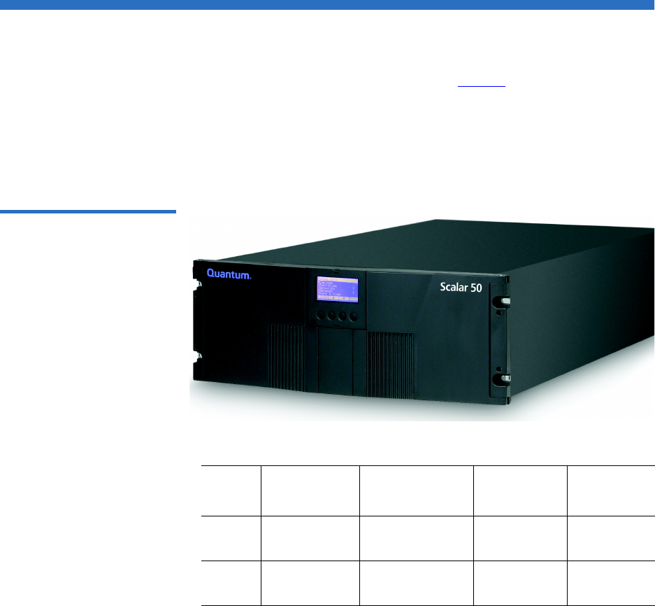
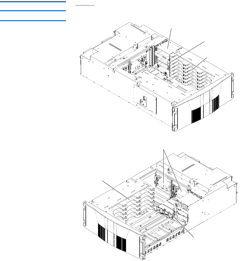
Overview
The Quantum Scalar 50 tape library (see figure 1) is an automated tape
storage and retrieval device that may consist of up to 4 tape drives and up
to 32 SDLT or 38 LTO tape cartridges. Cartridges are stored in two
removable cartridge magazines and two fixed slots. Both SDLT and LTO
tape cartridges can be installed in a single library as long as the
appropriate magazines and drives are installed.
Figure 1 Scalar 50
# Tape
Drives # Magazines
# Fixed
Slots
#
Cartridges
SDLT 0 - 2 2 (15 slots per
magazine)
232
LTO 0 - 4 2 (18 slots per
magazine)
238
Chapter 1 Library Description
Overview
Quantum Scalar 50 User’s Guide 3
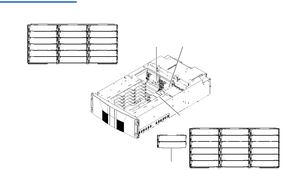
Figure 2 Slot Numbering,
Scalar 50 SDLT
0000
0030
0001
0002
0003
0004
0005
0006
0007
0008
0009
0010
0011
0012
0013
0014
0015
0016
0017
0018
0019
0020
0021
0022
0023
0024
0025
0026
0027
0028
0029
0031
Tape
drive 2
Tape
drive 1
Hand Top
Fixed cartridge slotsSDLT magazines have 15 cartridges
Mag 1
Mag 2
Chapter 1 Library Description
Overview
Quantum Scalar 50 User’s Guide 4
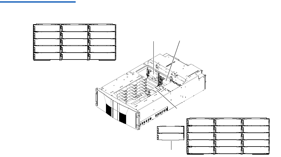
Figure 3 Slot Numbering,
Scalar 50 LTO
0027
0017
0036
0037
0000
0001
0002
0003
0004
0006
0007
0008
0009
0010
0012
0013
0014
0015
0016
0019
0020
0021
0022
0023
0025
0026
0029
0031
0032
0033
0034
0035
0005 0011
003000240018
0028
Tape
drive 1
Tape
drive 2
Hand Top
Fixed cartridge slots
LTO magazines have 18 cartridges
Mag 1
Mag 2

Chapter 1 Library Description
Tape Drives
Quantum Scalar 50 User’s Guide 5
Tape Drives
Scalar 50 tape libraries are equipped with either SCSI or native Fibre
Channel tape drives. SCSI buses are SCSI-2 fast/wide (8/16 bit), Ultra 3
SCSI, Ultra 160, or Ultra 320 SCSI, depending on the drives installed.
LVD SCSI configurations have a maximum allowable bus length of 12
meters. To determine the cable length of the bus, measure the lengths of
the SCSI cables connecting each device to that bus and add those lengths
together. To that total length, add 12.25 inches (31.10 cm) for the internal
SCSI cable length of each SCSI tape drive.
Tape Drive Types 1The Scalar 50 tape library support the following tape drives:
• Quantum DLT-S4 (SCSI and Native Fibre Channel)
• Quantum Half-Height LTO-3 (SCSI and Native Fibre Channel)
• HP LTO-3 (SCSI and Native Fibre Channel)
• HP LTO-4 (SCSI and Native Fibre Channel)
• HP Half-Height LTO-4 (SAS)
Scalar 50 library can support mixed media types, mixed interface types
(Fibre Channel and SCSI) as well as mixed form factors within the same
library. Example: The Scalar 50 can contain both LTO full height drives
with LTO half-height drives in the same library.
Refer to the following tables for tape drive performance characteristics.
Both SDLT and LTO tape drive can exist in the same library as long as the
appropriate magazines are installed in the library.
Table 1 DLT-S4 Performance
Characteristics Quantum Scalar 50 DLT-S4 Model (drives/slots) 2/32
Capacity in Terabytes (TB) (800 GB per cartridge) 25.6
*Compressed Capacity in TB (1600 GB per cartridge) 51.2
Throughput (GB/hr) based on 60 MB/sec transfer rate
(2 tape drives installed)
432
*Compressed Throughput (GB/hr) based on 120 MB/
sec transfer rate (2 tape drives installed)
864

Chapter 1 Library Description
Tape Drives
Quantum Scalar 50 User’s Guide 6
* Compressed capacity assumes a 2:1 compression ratio.
Table 2 Quantum LTO-3 (Half-
Height) Performance
Characteristics
* Compressed capacity assumes a 2:1 compression ratio.
Table 3 HP LTO-3 (Full Height)
Performance Characteristics
* Compressed capacity assumes a 2:1 compression ratio.
Quantum Scalar 50 Quantum LTO-3 Half-Height Model
(drives/slots) 4/38
Capacity in Terabytes (TB) (400 GB per cartridge) 15.2
*Compressed Capacity in TB (800 GB per cartridge) 30.4
Throughput (TB/hr) based on 80 MB/sec transfer rate (4
tape drives installed)
1.1
*Compressed Throughput (TB/hr) based on 160 MB/sec
transfer rate (4 tape drives installed)
2.3
Quantum Scalar 50 HP LTO-3 Model (drives/slots) 2/38
Capacity in Terabytes (TB) (400 GB per cartridge) 15.2
*Compressed Capacity in TB (800 GB per cartridge) 30.4
Throughput (TB/hr) based on 80 MB/sec transfer rate (2
tape drives installed)
.576
*Compressed Throughput (TB/hr) based on 160 MB/sec
transfer rate (2 tape drives installed)
1.1

Chapter 1 Library Description
Tape Drives
Quantum Scalar 50 User’s Guide 7
Table 4 HP LTO-4 (Half-
Height) Performance
Characteristics
* Compressed capacity assumes a 2:1 compression ratio.
Table 5 HP LTO-4
Performance Characteristics
If a drive experiences read/write errors when the AutoClean function is
enabled, the library issues an error message stating that drive cleaning is
required. Without user intervention, the library hand replaces the data
cartridge with a cleaning cartridge. When the cleaning procedure
finishes, the library hand returns the data cartridge to the drive.
Quantum Scalar 50 HP LTO-4 Half-Height Model
(drives/slots) 1/38
Capacity in Terabytes (TB) (800 GB per cartridge) 30.4
*Compressed Capacity in TB (1600 GB per cartridge) 60.8
Throughput (TB/hr) based on 80 MB/sec transfer rate (4
tape drives installed)
1.1
*Compressed Throughput (TB/hr) based on 160 MB/sec
transfer rate (4 tape drives installed)
2.3
Quantum Scalar 50 HP LTO-4 Model (drives/slots) 2/38
Capacity in Terabytes (TB) (800 GB per cartridge) 30.4
*Compressed Capacity in TB (1600 GB per cartridge) 60.8
Throughput (TB/hr) based on 120 MB/sec transfer rate (2
tape drives installed)
.864
*Compressed Throughput (TB/hr) based on 240 MB/sec
transfer rate (2 tape drives installed)
1.7
Note: When a cleaning cartridge has completed its 20-use limit, it is
automatically exported from the library, requiring a new one
to be loaded through the load port.

Chapter 1 Library Description
Library Features
Quantum Scalar 50 User’s Guide 9
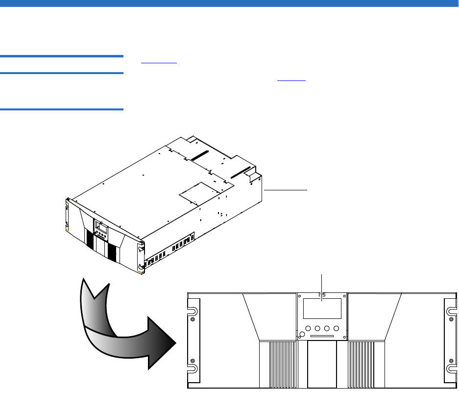
Table 6 Front Panel Features
Feature Description
Operator
control panel
(OCP)
The operator control panel consists of the following elements:
• OCP display The OCP displays library status information and allows you to
access the library menus. These menus allow you to view or
change the library settings and run diagnostic tests.
The OCP is discussed in detail in chapter 2.
•Five OCP
buttons
These buttons in combination with the OCP are used to scroll
through screens and select options or commands. The
functionality of these buttons changes depending on the
currently displayed OCP screen. The power button is used to
turn the library on and off.
• Light emitting
diode (LED)
indicator
The operator control panel has one LED indicators:
• Steady green - indicates a idle state
• Flashing green - indicates a busy state
• Flashing amber - indicates an attention state
• Steady amber - indicates an error
Magazine
access doors
These doors protect the data cartridge magazines.

Chapter 1 Library Description
Library Features
Quantum Scalar 50 User’s Guide 11
Each cartridge magazine holds 15 SDLT cartridges or 18 LTO cartridges.
The bins in the left magazines are numbered from 1 through 15 (18 in
LTO libraries) from front to back. The bins in the right magazines are
numbered from 1 through 15 (18 in LTO libraries) from back to front. The
Scalar 50 has two fixed slots behind the right magazine.
A bar code reader is attached to the library’s robotic hand. This bar code
reader automatically identifies the cartridges in the library, if the
cartridges are fitted with acceptable bar code labels.
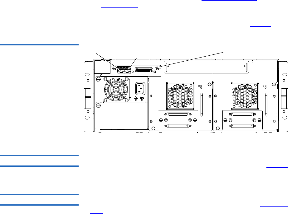
Back Panel 1The library back panel provides access to the following items:
•System Controller Board (SCB)
•Power Supplies
•CPCI Card Cage
•Tape Drives
System Controller Board (SCB) 1
The system controller board (SCB) contains the library firmware and
processor. Two Ethernet ports. One port for remote management and the
other for internal communications with add-on CPCI cards such as the
TC2201 iSCSI bridge.
Power Supplies 1
The power supplies provide redundant power to the library. The Scalar
50 can contain up to two power supplies (one power supply in the base
unit).
CPCI Card Cage 1
The CPCI (compact PCI) card cage provides space for option cards such
as the TC2201 iSCSI bridge. The Scalar 50 can contain one option card.
Chapter 1 Library Description
Library Features
Quantum Scalar 50 User’s Guide 12
Tape Drives 1
The Scalar 50 can contain up to four tape drives.
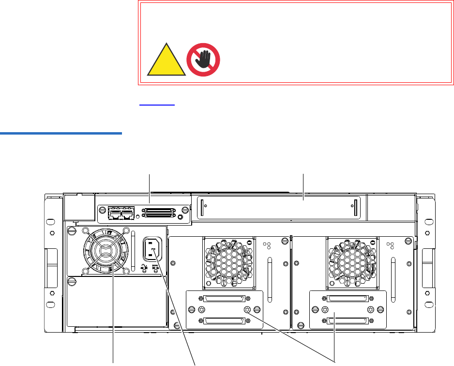
Figure 6 illustrates the back panel of the Scalar 50 library.
Figure 6 Scalar 50 Back Panel
Tape
drives
CPCI card cage
System controller board
Power connectorsPower supply
Warning: Hazardous Moving Parts.
Keep Fingers and Other Body
Parts Away When Removing
and Installing Tape
Drives.
Warning: Hazardous Moving Parts.
Keep Fingers and Other Body
Parts Away When Removing
and InstallingTape
Drives.
Warnung: Gefährliche bewegliche
Teile. Halten Sie die
Finger und andere
Körperteile weg, wenn
Sie Bandlaufwerke
entfernen und
anbringen.
Warnung: Gefährliche bewegliche
Teile. Halten Sie die
Finger und andere
Körperteile weg, wenn
Sie Bandlaufwerke
entfernen und
anbringen.

Chapter 1 Library Description
DLTSage™ Tape Security
Quantum Scalar 50 User’s Guide 13
DLTSage™ Tape Security
The Scalar tape library with DLT-S4 tape drives are capable of utilizing
DLTSage Tape security. DLTSage Tape Security is a unique solution
designed to prevent unauthorized access to tape cartridges which is
particularly valuable when protecting tapes that are transported offsite.
DLTSage Tape Security is a firmware feature designed into the DLT-S4
tape drive which uses an electronic key to prevent or allow reading and
writing of data on to a tape cartridge. This key is managed through the
remote management pages of the Scalar 50 tape library (see chapter 3,
“Quantum Scalar 50 Remote Management,”). DLTSage Tape Security is
available at no additional cost as an integrated feature in of the DLT-S4
tape drive and Scalar 50 tape library.
Mixed Media Support
The Scalar 50 tape library is capable of supporting mixed media (SDLT
and LTO media) and a mixture of tape drives in the same library frame.
You must have at least one magazine type (SDLT or LTO) for each tape
drive type (SDLT or LTO).
Capacity on Demand
Capacity on demand provides the ability to upgrade the storage capacity
of a library by using a software capacity key that grants access to
additional magazine slots. The Scalar 50 library has two capacity levels
(see table 7):
•Level 1 - default capacity (four magazine columns starting with the
three columns of the left-hand magazine and including the back
column of the right-hand magazine)
•Level 2 - full capacity (all six columns of the left and right magazines
and all physical slots in the system including stacked libraries)

Chapter 1 Library Description
Capacity on Demand
Quantum Scalar 50 User’s Guide 14
The two fixed slots located in every library are always available for use.
Table 7 Scalar 50 Capacity
Levels
Contact your Quantum Sales representative to acquire additional license
keys.
Enabling Capacity on
Demand 1If your Quantum Scalar 50 has not already been enabled with the full slot
capacity, you must complete the following procedure:
1Retrieve and record the Scalar 50 library serial number.
2Access the COD website and follow the instructions by providing the
Library serial number to obtain your new License Key for your
additional capacity purchase.
The COD website URL is: www.quantum.com/capacity/scalar50.
3Record your new License Key and then install it into the Library to
increase your slot capacity (see Library on page 101 for more
information on enabling capacity on demand).
Licensed Capacity (Slot Count)
Capacity Level LTO SDLT
Level 1 26 22
Level 2 38 32
Note: Partitioning cannot be used unless all libraries are at FULL
capacity.
Note: If your libraries are in a stacked configuration, all libraries
must be at FULL capacity. PX502 libraries are automatically at
full capacity.

Chapter 1 Library Description
Library Scalability (Stacked Configurations)
Quantum Scalar 50 User’s Guide 15
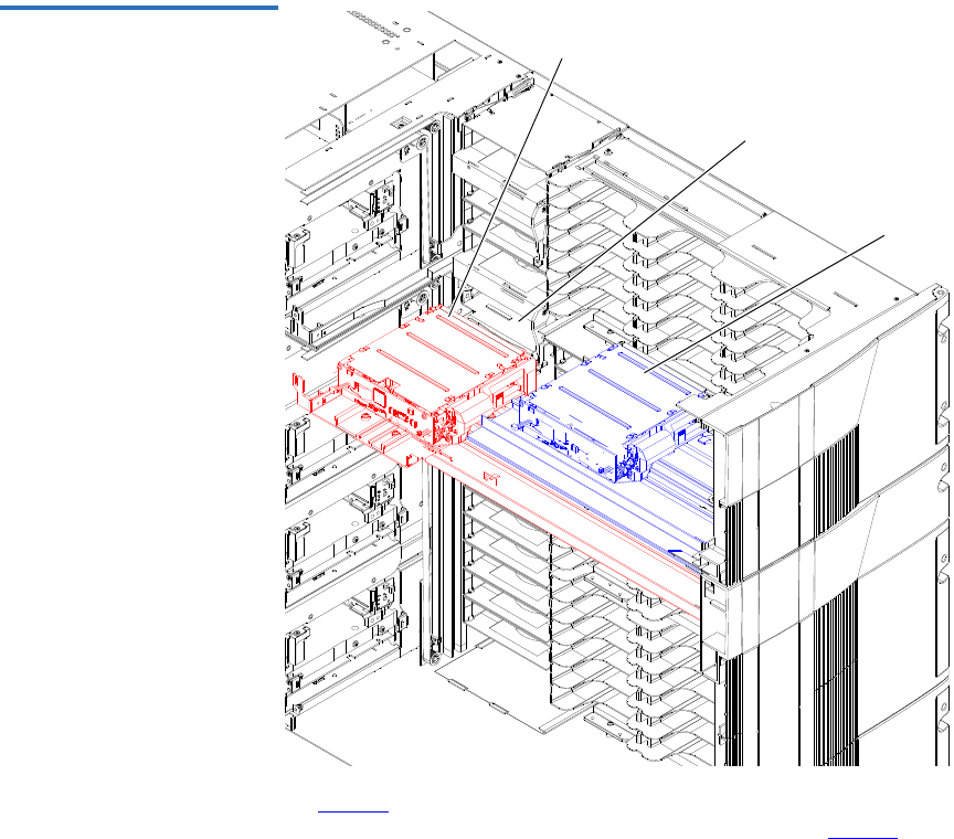
Library Scalability (Stacked Configurations)
The Scalar 50 library modules can be used as stand-alone libraries, or
combined with other Scalar 50 library modules in a standard 19-inch rack
to form a larger library system (called a multiple library stack). The
multiple library or stacked configuration appears as a single large
capacity library (or multiple libraries if partitioned) to the host (see
figure 7).
Multiple Library Stack
Requirements 1To ensure the proper operation of your multiple library stack, review the
following list of multiple library stack requirements:
• Multiple library stacks that contain a Scalar 50 can NOT exceed two
library cabinets.
• The Scalar 50 must be the Master library in a multiple library stack
containing PX502 libraries.
• The Master library must always be in the bottom most position in the
library stack.
• If a Scalar 50 is stacked with PX502 libraries, the PX502 can NOT
contain an HP LTO-2 tape drive or a FC1202 Fibre Channel bridge.
These devices are not supported by Scalar 50.
• All Scalar 50 libraries must have full capacity enabled.
• A library that contains SAS drives cannot be shared with SCSI or
Fibre Channel libraries.
• If your Scalar 50 is not already enabled with full slot capacity, you
must initially configure the Scalar 50 libraries and enable Full
capacity with a Capacity Key before configuring the cabinets as
Master and Slave libraries (see Library on page 125 for more Capacity
Key information).
Chapter 1 Library Description
Library Scalability (Stacked Configurations)
Quantum Scalar 50 User’s Guide 16
Figure 7 Multiple Library
Stack (Cross Section
Bottom hand lifting pass
through into top library
Pass through in top
library
Top hand
Table 8 lists the capacities of all the sizes of multiple library
stacks created using LTO Scalar 50 library modules. Table 9 lists
the capacities of all the sizes of multiple library stacks created
using SDLT Scalar 50 library modules.

Chapter 1 Library Description
Library Scalability (Stacked Configurations)
Quantum Scalar 50 User’s Guide 17
Table 8 Capacity, Scalar 50
Multiple Library Stack - LTO
(42U High Rack)
# of Scalar
50 Library
Modules
Max. # of
Tape Drives
# of
Cartridges*
*.The values in the # of Cartridges and Capacity columns assume that all the magazines and fixed cartridge slots are fully
populated with data cartridges.
†Compressed values assume 2:1 compression ratios.
12 full height/
4 half height
38 15.2 30.4 32 64
24 full height/
8 half height
76 28.8 57.6 64 128
Table 9 Capacity, Scalar 50
Multiple Library Stack - SDLT
(42U High Rack)
# of Scalar
50 Library
Modules
Max. # of
Tape Drives
# of
Cartridges*
*.The values in the # of Cartridges and Capacity columns assume that all the magazines and fixed cartridge slots are fully populated
with data cartridges.
†Compressed values assume 2:1 compression ratios.
12 full height/
4 half height
32 26.4 52.8
24 full height/
8 half height
64 52.8 105.6
Capacity (in TB)
LTO
Quantum/HP LTO Gen 3 HP LTO Gen 4
Native Compressed†Native Compressed†
Capacity (in TB)*
SDLT
DLT-S4
Native Compressed†

Chapter 1 Library Description
Getting Started
Quantum Scalar 50 User’s Guide 18
Getting Started
This chapter describes the procedures necessary to get your Quantum
Scalar 50 library up and running. Have the following equipment and
accessories available before installing the library:
• SCSI cables to support 1 host bus adapter (HBA) per two tape drives
• SCSI, SAS, or Fibre Channel HBAs in the host
•2 tape drives per SCSI bus
• Power source (see appendix A on page 177 for power requirements)
• Tape cartridges (LTO and/or SDLT)
After the Quantum Scalar 50 is in it’s final location, the following steps
are required to complete the installation:
•Installing the Quantum Scalar 50
•Cabling the Quantum Scalar 50 Series
•Loading Tape Cartridges
•Initial Configuration
Installing the Quantum
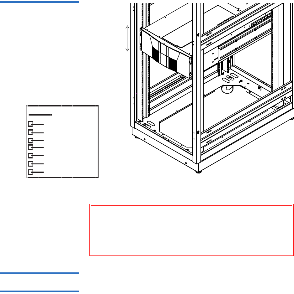
Scalar 50 1The Scalar 50 library modules fit into a standard 19-inch wide rack. Refer
to figure 8 for rack space requirements. Complete mounting information
is provided in the Quantum Scalar 50 Series Quick Start (PN 81-81767).
Note: Quantum ships sufficient SCSI cables and terminators
with the libraries to set up two-drives per SCSI bus. One
tape drive per SCSI bus may be necessary for optimum
performance. Refer to your tape drive documentation.
Chapter 1 Library Description
Getting Started
Quantum Scalar 50 User’s Guide 19
Figure 8 Rack Space
Requirements
*1U = 1. 75 in (44 .45 mm)
.625 in (15.9 mm)
.625 in (15.9 mm)
.5 in (12.7 mm)
.625 in (15.9 mm)
.625 in (15.9 mm)
Top of rack
.312 in (7.92 m m)
.5 in (12.7 mm)
Hole pattern
1 Scalar 50 library
module (4U)
Warning: If the rack is empty at the time of installation, do NOT
install the Scalar 50 modules too high in the rack. The
combined weight of the components may cause the rack
to become “top heavy” and unstable if installed in the top
of an empty rack. If installing a multiple library stack,
begin installing the bottom library module first.
Cabling the Quantum
Scalar 50 Series 1After the Quantum Scalar 50 is in its final location, the tape drives and
system controller board must be connected to the backup host system(s).
To cable the Quantum Scalar 50:
Chapter 1 Library Description
Getting Started
Quantum Scalar 50 User’s Guide 20
1The Scalar 50 tape drives and system controller board are accessed
from the back of the library (refer to Connecting to Host
Workstations on page 31).
2Connect Ethernet port located on the back of the library on the
system controller board to the local area network (see figure 9).
Figure 9 Connecting the
Library to the Local Area
Network
Ethernet port System controller boardInternal communication
with TC2201 CPCI card
Loading Tape Cartridges 1Before operating the library, load the appropriate tape cartridges (LTO or
SDLT) into the library starting with the left-hand magazine (see figure 2
and figure 3 for slot locations).
Initial Configuration 1The Quantum Scalar 50 must be initially configured with an IP address
before the remote management software is available. Refer to Using the
OCP on page 37 for information on configuring your Scalar 50 network
information and preparing for operation.

Quantum Scalar 50 User’s Guide 21
Chapter 2
2Basic Library Operations
This chapter describes the following basic library operating procedures:
•Installing Tape Cartridges
•Preparing the Library for Operation
•Turning the Library On and Off
•Using the OCP
•Load Port Configuration
Installing Tape Cartridges
To install tape cartridges:
1Label each cartridge (see “SDLT Cartridges” on page 24 and “LTO
Cartridges” on page 26 for information on cartridge labels).
2Set the write-protect switch to either write protect or write enable
(see “SDLT Cartridges” on page 24 and “LTO Cartridges” on
page 26 for information on write-protect switches).

Chapter 2 Basic Library Operations
Installing Tape Cartridges
Quantum Scalar 50 User’s Guide 22
3Place cartridges (right side up) in the fixed slots and magazines:
aOpen the library doors (see “Library Operations” on page 45 to
open the library doors).
bRemove the magazines (see “Library Operations” on page 45 to
release the magazines).
cLoad the tape cartridges in the magazines and fixed bins. It is
recommended to start loading tape cartridges in magazine 1, bin
0000 (see figure 2 on page 3 and figure 3 on page 4 for magazine
and bin locations).
Warning: Do NOT reach into the library to load tape cartridges
into the fixed bins. Use the Move page located on the
Operations tab from the remote management pages
(see chapter 3 on page 63) to move tape cartridges
from the magazines into the fixed bins.
dReplace the magazines in the library.
eClose the library doors.
Caution: Placing the cartridges in the bins upside down can
cause damage to the library (see figure 11 for SDLT
cartridges and figure 12 for LTO cartridges).
Caution: Handle tape cartridges with care. Do not drop or bang
them, or place them near sources of electromagnetic
interference. Rough handling can displace the tape
leader, making the cartridge unusable and potentially
hazardous to the tape drives. If a tape is dropped,
discard and replace with a new tape. Loss of data
could result from damaged tape cartridges inserted in
tape drives.
Note: You have approximately 10 seconds to open the doors and
remove the magazines. If you did not complete the
operation, repeat the steps.
Chapter 2 Basic Library Operations
Installing Tape Cartridges
Quantum Scalar 50 User’s Guide 23
Taking ESD Precautions 2Components within the Scalar 50 contain static-sensitive parts. To
prevent damage to these parts while performing installation,
maintenance, or replacement procedures, observe the following
precautions:
• Keep the cabinet turned off during all installation, maintenance, and
replacement procedures.
• Keep the cabinet power cord connected to a grounded power outlet
except when working with AC electrical components.
Warning: Avoid contact with the power supplies, EMI filter, and all
other AC electrical components while the cabinet is
connected to a power outlet.
Unplug all AC cords to remove power from equipment.
• Use an antistatic wrist strap when touching internal cabinet
components. To use the wrist strap properly, place the band around
your wrist and attach the clip to the cabinet frame. Keep the strap on
until you are ready to close the cabinet doors.
• Keep static-sensitive parts in their shipping containers until ready for
installation.
• Do not place static-sensitive parts on any metal surface. If you need to
put down a static-sensitive part, place it inside its protective shipping
bag or on a grounded antistatic mat.
• Avoid direct contact with static-sensitive parts. Avoid touching
connectors and discrete components.
• Close cabinet door and access panel when not working on the
cabinet.

Chapter 2 Basic Library Operations
Installing Tape Cartridges
Quantum Scalar 50 User’s Guide 24
• Be very careful when installing the cabinet or handling components
in dry climates or environments where cold weather heating is used.
Environments such as these with lower relative humidity have
greater potential to produce static electricity.
SDLT Cartridges 2The following section shows you how to label SDLT tape cartridges, as
well as setting the write-protect switch and proper orientation.
Labeling 2
The Scalar 50 is a multi-media library, meaning multiple drive and tape
cartridge types can be present in a single library. Barcode labels are
attached to each tape cartridge to differentiate the different tape cartridge
types (SDLT, LTO, and cleaning cartridges).
The SDLT cartridge label has eight characters (e.g. AAANNNS#). The
first six characters are called the volume identifier which is made up of
three alpha characters and three numeric characters. These characters
allow each cartridge to have a unique identifier. The last two characters
are called the media identifier and indicate the following media types:
•V4 = DLT-V4
• S1 = SDLT 220
• S2 = SDLT 320
• S3 = SDLT 600
•S4 = DLT-S4
Note: In environments with high potential for static electricity,
take additional precautions such as the use of an antistatic
smock or a grounded antistatic mat.
Note: Quantum highly recommends using barcode labels provided
by Quantum. Also, use the appropriate barcode labels for your
drive type. Do not use older barcode labels on tape cartridges
for newer drive types.
Chapter 2 Basic Library Operations
Installing Tape Cartridges
Quantum Scalar 50 User’s Guide 25
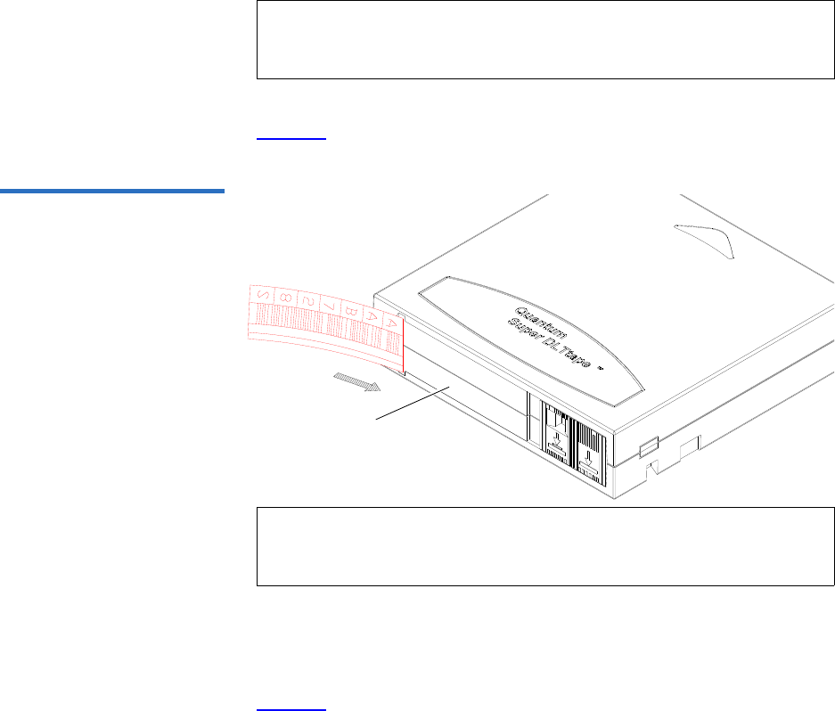
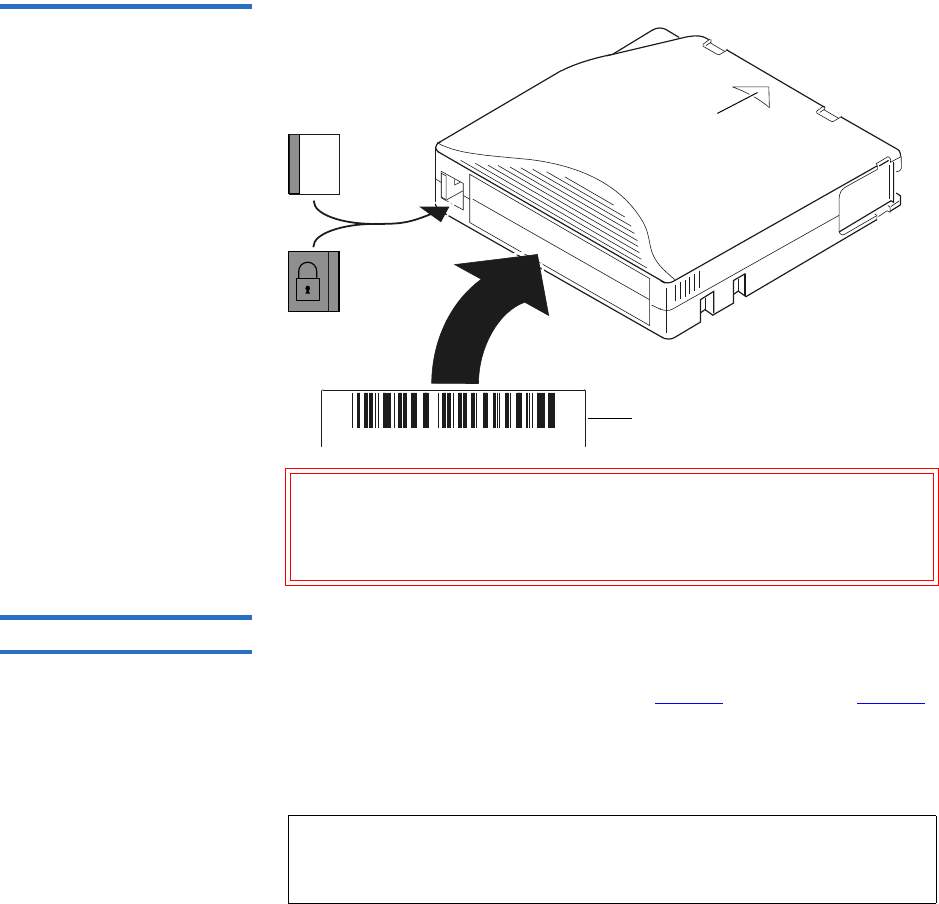
Place the label in the slide-in slot on the front of the cartridge (see
figure 10).
Figure 10 Inserting a Barcode
Label (SDLT)
Slide-in slot
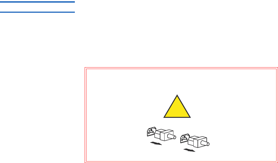
Setting the Write-Protect Switch 2
Each tape cartridge has a write-protect switch similar to that shown in
figure 11. This switch determines whether new data can be written to the
cartridge (write-enabled) or whether data on the cartridge is protected
from being erased or overwritten (write-protected). Set the write-protect
switch to enabled when inserting new cartridges into the library. Set the
write-protect switch to protected archiving tape cartridges.
Note: You cannot choose the sequence of labels inside the bar code
label packs. No two packs are ever the same to avoid issues
with duplicate bar code IDs.
Note: Only use barcode labels that have been designed for
cartridges. Do not adhere labels to a cartridge anywhere
except the slide-in slot.
Chapter 2 Basic Library Operations
Installing Tape Cartridges
Quantum Scalar 50 User’s Guide 26
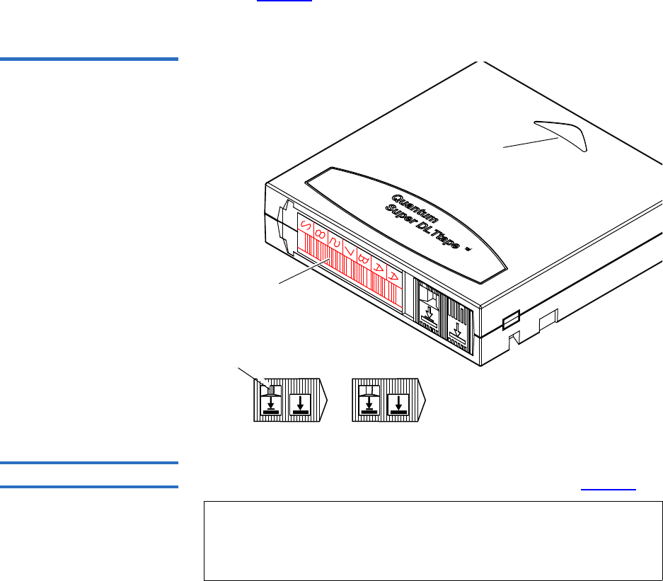
Proper Insertion Orientation 2
Refer to figure 11 for proper label placement, write protection settings
and insertion orientation.
Figure 11 SDLT Cartridges
Barcode label
Insertion arrow
Insert this end into the slot
Orange
window Write
protect
Write
enable
(SDLT cartridge shown)
Slide right (default)
Slide left
LTO Cartridges 2LTO tape cartridges are different in size to the SDLT cartridges as well as
in the barcode labeling and write-protect switch setting (see figure 12).
Note: Quantum highly recommends using barcode labels provided
by Quantum. Also, use the appropriate barcode labels for your
drive type. Do not use older barcode labels on tape cartridges
for newer drive types.

Chapter 2 Basic Library Operations
Installing Tape Cartridges
Quantum Scalar 50 User’s Guide 27
Labeling 2
The Scalar 50 is a multi-media library, meaning multiple drive and tape
cartridge types can be present in a single library. Barcode labels are
attached to each tape cartridge to differentiate the different tape cartridge
types (SDLT, LTO, and cleaning cartridges).
The LTO cartridge label has eight characters (e.g. AAANNNL#). The first
six characters are called the volume identifier which is made up of three
alpha characters and three numeric characters. These characters allow
each cartridge to have a unique identifier. The last two characters are
called the media identifier and indicate the following media types:
• L1 = LTO generation 1 (LTO)
• L2 = LTO generation 2 (LTO-2)
• L3 = LTO generation 3 (LTO-3)
• L4 = LTO generation 4 (LTO-4)
Adhesive-backed barcode labels are used on LTO tape cartridges. Refer
to figure 12 for proper label placement, write protection settings and
insertion orientation.
Note: You cannot choose the sequence of labels inside the bar code
label packs. No two packs are ever the same to avoid issues
with duplicate bar code IDs.
Chapter 2 Basic Library Operations
Installing Tape Cartridges
Quantum Scalar 50 User’s Guide 28
Figure 12 LTO Cartridges
A B C 1 2 3 L 1
Barcode label
Insertion arrow
Insert this end into the slot
Write
protect
Write
enable
Slide left (default)
Slide right
Caution: LTO tape drive media cannot be degaussed due to the fact
that it uses "magnetic servos." Do not attempt to degauss
LTO tape drive media. If this media is degaussed, it will
no longer work.
Cleaning Cartridges 2Cleaning cartridges are used when a tape drive within the library
requires cleaning. When Autoclean is enabled (either through the OCP or
remote management screens), the library will automatically clean the
tape drive when needed. A fixed bin (see figure 2 on page 3 and figure 3
on page 4 for bin locations) is generally used to store a cleaning cartridge,
however, the cartridge can be placed anywhere in the library. When the
library completes the inventory, the system stores the cleaning cartridge
location so it will be available when a tape drive requires cleaning.
Note: You must attach the appropriate cleaning cartridge barcode
label (SDLT or LTO) to the cleaning cartridge or the library
will mark it as unrecognizable media.
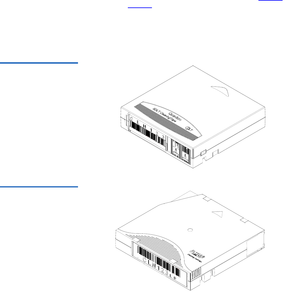
Chapter 2 Basic Library Operations
Installing Tape Cartridges
Quantum Scalar 50 User’s Guide 29
SDLT and LTO cleaning cartridge labels begin with CLN (see figure 13
for SDLT and figure 14 for LTO):
• SDLT cleaning cartridge labels are in the following format:
CLN###S#
• LTO cleaning cartridge tables are in the following format:
CLN###L#
Figure 13 SDLT Cleaning
Cartridges
Figure 14 LTO Cleaning
Cartridges

Chapter 2 Basic Library Operations
Preparing the Library for Operation
Quantum Scalar 50 User’s Guide 30
Preparing the Library for Operation
To prepare the cabinet for operation:
•Close the Cabinet Doors and Access Panels
•Connecting to Host Workstations
Close the Cabinet Doors
and Access Panels 2The Scalar 50 library has doors covering the tape cartridge magazines.
1Close the front doors until they latch (see figure 15)
Figure 15 Closing the Scalar
50 Front Doors
Right door
Left door

Chapter 2 Basic Library Operations
Preparing the Library for Operation
Quantum Scalar 50 User’s Guide 31
Connecting to Host
Workstations 2Connect the SCSI, SAS or Fibre Channel cables as shown in the following
figures:
•Scalar 50 Cable Configuration (SCSI Full Height Drives)
•Scalar 50 Cable Configuration (Native Fibre Channel Full Height
Drives)
•Scalar 50 Cable Configuration (SCSI Half-Height Drives)
•Scalar 50 Cable Configuration (SAS Half-Height Drives)
•Scalar 50 Cable Configuration (Native Fibre Channel Half-Height
Drives)
Caution: The SCSI cables used to connect to the library system
controller board MUST have an offset connector. Using a
straight-in SCSI connector may damage the system
controller board.
Stacked Configuration 2
•Scalar 50 Cable Configuration (Stacked)
Note: Quantum ships sufficient SCSI cables and terminators with the
libraries to set up two-drives per SCSI bus.
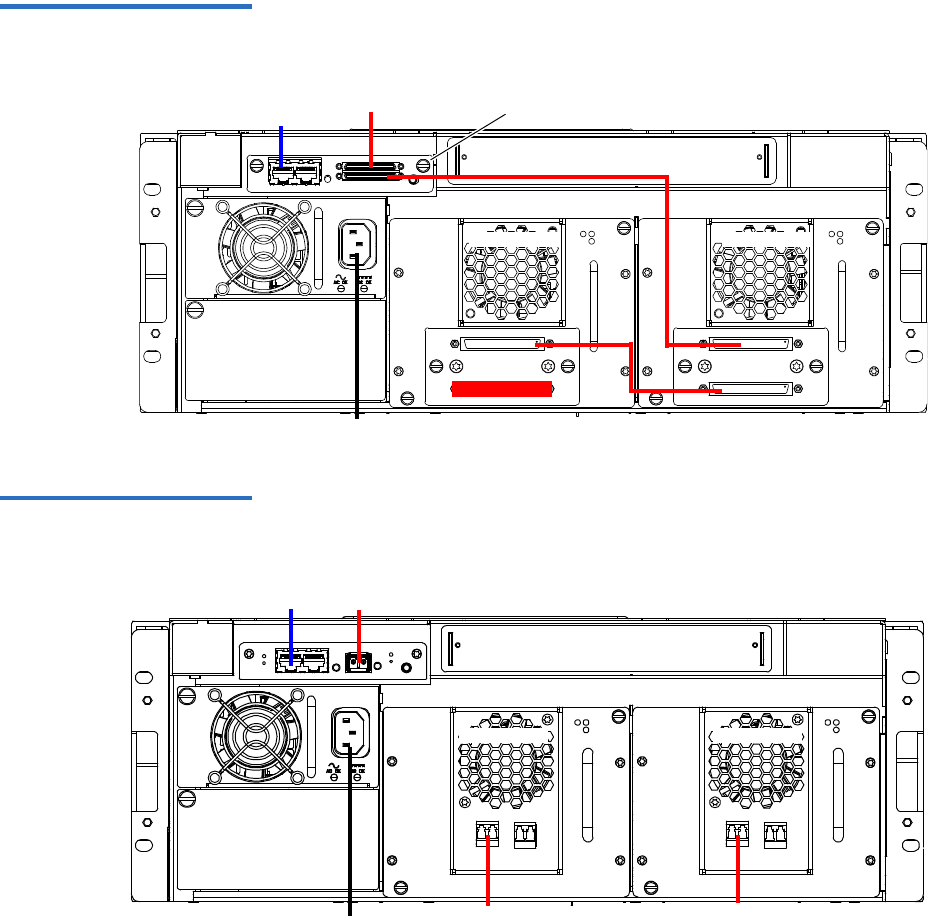
Chapter 2 Basic Library Operations
Preparing the Library for Operation
Quantum Scalar 50 User’s Guide 32
Figure 16 Scalar 50 Cable
Configuration (SCSI Full Height
Drives)
Back of Library
SCSI hostEthernet
Power
System Controller Board
Tape drive 1Tape drive 2
Figure 17 Scalar 50 Cable
Configuration (Native Fibre
Channel Full Height Drives)
Back of Library
Ethernet
Power
Tape drive 2 Tape drive 1
LTO Tape drives
shown. SDLT drives
have a single FC port
Fibre Channel
host/SAN
Fibre Channel
host/SAN
Fibre Channel host/SAN
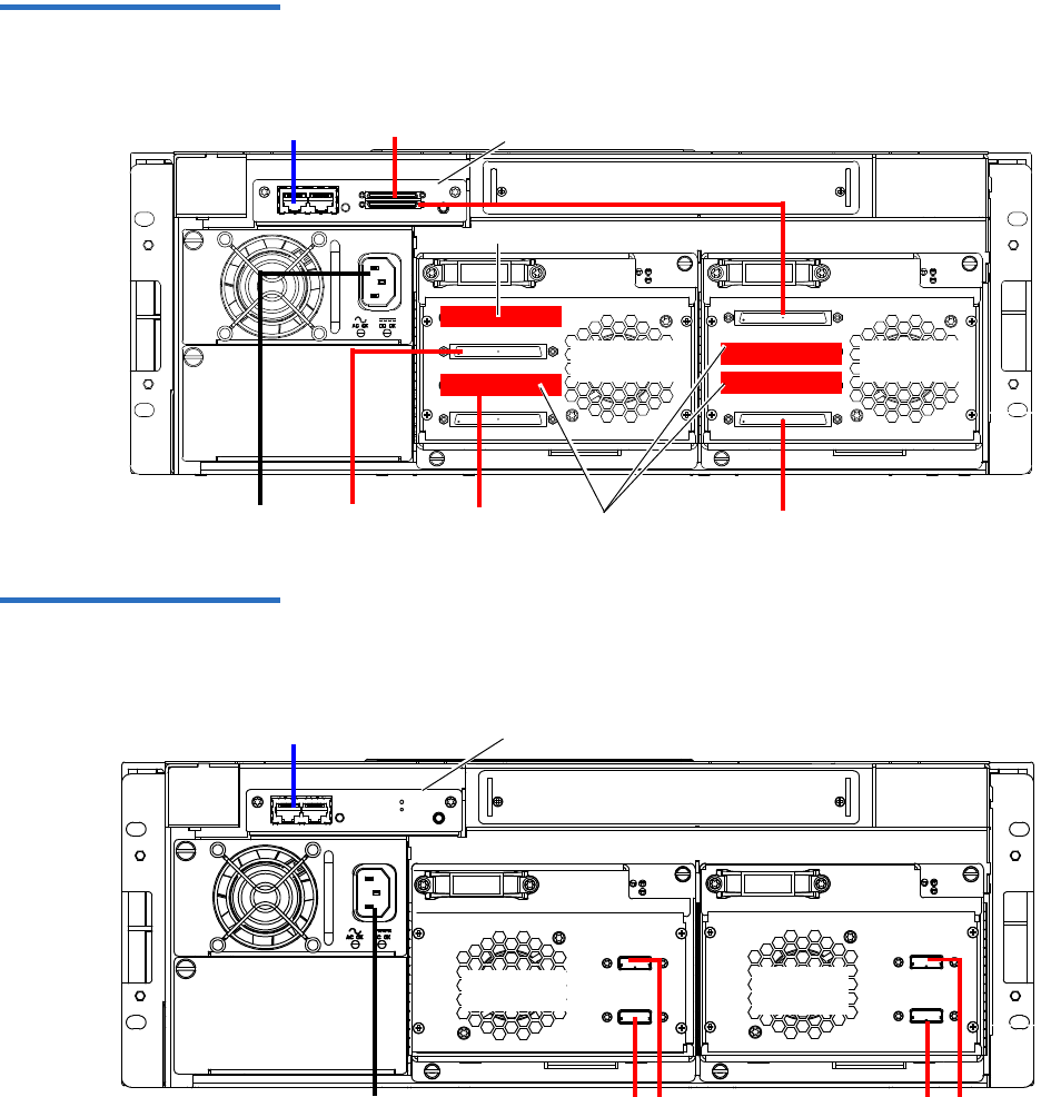
Chapter 2 Basic Library Operations
Preparing the Library for Operation
Quantum Scalar 50 User’s Guide 33
Figure 18 Scalar 50 Cable
Configuration (SCSI Half-
Height Drives)
Ethernet
Power
Back of Library
SCSI host
Terminator
Tape drives
1 and 2
Tape drives
3 and 4
SCSI host
Terminator
SCSI System Controller Board
SCSI hostSCSI host
Figure 19 Scalar 50 Cable
Configuration (SAS Half-Height
Drives)
Back of Library
Ethernet
Power SAS hosts
Tape drives
1 and 2
Surrogate Mode System
Controller Board ONLY
SAS hosts
Tape drives
3 and 4
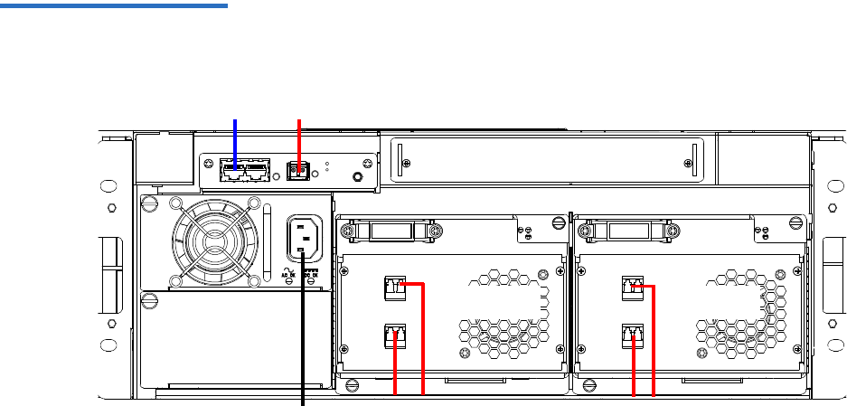
Chapter 2 Basic Library Operations
Preparing the Library for Operation
Quantum Scalar 50 User’s Guide 34
Figure 20 Scalar 50 Cable
Configuration (Native Fibre
Channel Half-Height Drives)
Back of Library
Ethernet
Power Fibre Channel
host/SAN
Fibre Channel
host/SAN
Tape drives
1 and 2
Tape drives
3 and 4
Fibre Channel host/SAN

Chapter 2 Basic Library Operations
Preparing the Library for Operation
Quantum Scalar 50 User’s Guide 35
Figure 21 Scalar 50 Cable
Configuration (Stacked)
Scalar 50 (master library)
Scalar 50 (slave library)
Host computer
Tap e
drive 2
Tape
drive 1
Tape
drive 1
Tap e
drive 2
Host computer
Ethernet
The library
host and
Ethernet
network are
connected only
to the Master
library.
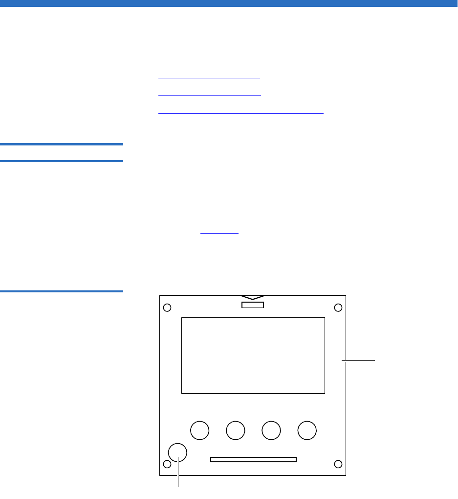
Chapter 2 Basic Library Operations
Turning the Library On and Off
Quantum Scalar 50 User’s Guide 36
Turning the Library On and Off
This section explains:
•Turning On the Library
•Turning Off the Library
•Placing the Library On-line or Off-line
Turning On the Library 2To turn on the library:
1Verify that:
• Power cables are firmly in place
• All doors are closed
2Push the power button located in the lower left-hand corner of the
OCP (see figure 22).
During the power up sequence, the library performs an inventory.
The power up sequence can take several minutes.
Figure 22 Turning On the
Library
Power button
OCP

Chapter 2 Basic Library Operations
Using the OCP
Quantum Scalar 50 User’s Guide 37
Turning Off the Library 2To turn off the library:
1Push the power button located on the front of the library and hold for
approximately 1 second (see figure 22).
The library begins the shutdown sequence. The shutdown sequence
can take up to two minutes to complete.
Placing the Library On-
line or Off-line 2With the library turned on, press the button corresponding to Ops on the
OCP to access the Operations screen. Select Library Operations and then
Library on/offline to turn the library off-line. Select Yes or No to confirm
the library state change. For more information on the Operations screen,
see “Library Operations” on page 45.
Using the OCP
The operator control panel (OCP) is located on the front of the library.
The menus on the OCP allow you to obtain information about the library,
execute library commands, and test library functions. Before using the
OCP to perform library functions, familiarize yourself with the:
•Home Screen
•OCP Buttons
Home Screen 2The first screen the OCP displays after library initialization is the main
screen. This screen displays library status and provides information on
the number of tape drives, slots, and serial number (see figure 23).
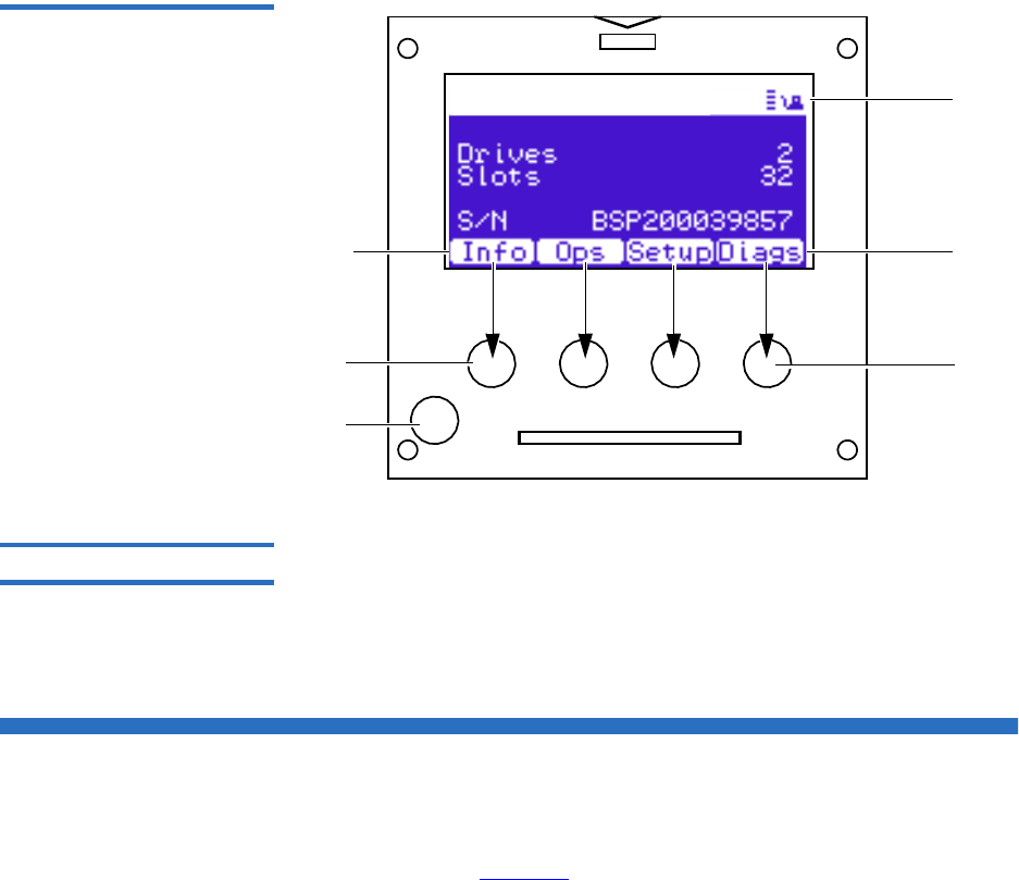
Chapter 2 Basic Library Operations
OCP Components
Quantum Scalar 50 User’s Guide 38
Figure 23 OCP Home Screen
Quantum Scalar 50
Power
button
Library
status
Button
labels
Push
buttons
Press this
button
To select this
function
OCP Buttons 2At the bottom of each OCP screen are four button labels. These labels
indicate the functions of the four push buttons below the OCP. To select a
function, press the push button directly below the button label on the
OCP screen. The OCP also contains a power button for turning the library
on and off.
OCP Components
The OCP allows the user to perform various functions on the Quantum
Scalar 50 library. Figure 24 provides a list of the OCP functionality
available from the Home screen.

Chapter 2 Basic Library Operations
OCP Components
Quantum Scalar 50 User’s Guide 39
Figure 24 OCP Component
Tree
Info menu
Overview
Firmware Information
Firmware revision
Date and time of rev.
Network Information
IP address
Network Mask
Gateway
System
Doors
Power Supply
Robotics
OCP
Drives
Hard Events
Soft Events
Code Update Events
Boot Events
Hardware Information
Event Logs
Library on/offline
Release Magazines
Park for Shipping
Library Operations
Search for label
Search for media ID
Find Tape
ElapsTm
Pcycles
SlotGet
SlotPut
SltRetG
SltRetP
DrvGet
DrvPut
DrvRetG
DrvRetP
Statistics
Health test
Self test
Calibration stats
Random load/unload
Random (slots only)
Random (drive focus)
Sequential bins
Sequential drives
System-level tests
Host bus
Stack role
Left load port
Right load port
Drive FUP from tape
Full Inventory
Cabinet
Barcode swap
Emulation
Auto clean
Configure Slots
Partitions
Set admin PIN
Set operator PIN
Security
DHCP
IP address
Subnet mask
Default gateway
Ethernet 0
Network
Time zone
Standard time
Daylight savings time
Date and Time
DrvLdR
DrvUnlR
XYmove
Zmove
Pmove
Rmove
XYretry
Zretry
Pretry
Rretry
Ops menu Setup menu Diags menu
Left mag(s)
Right mag(s)
MoveTape
Drives
Hand/Top Passthru
Drive Operations
Scan Inventory
Drive(s)
Pwr on
Pwr off
reset
Drive Type
Serial Number
Firmware Revision
XY test
Z test
Rotation stats
Translation test
Camera test
Temperature test
Home position
Component tests
XYZ test
Hand assembly test
Subsystem tests
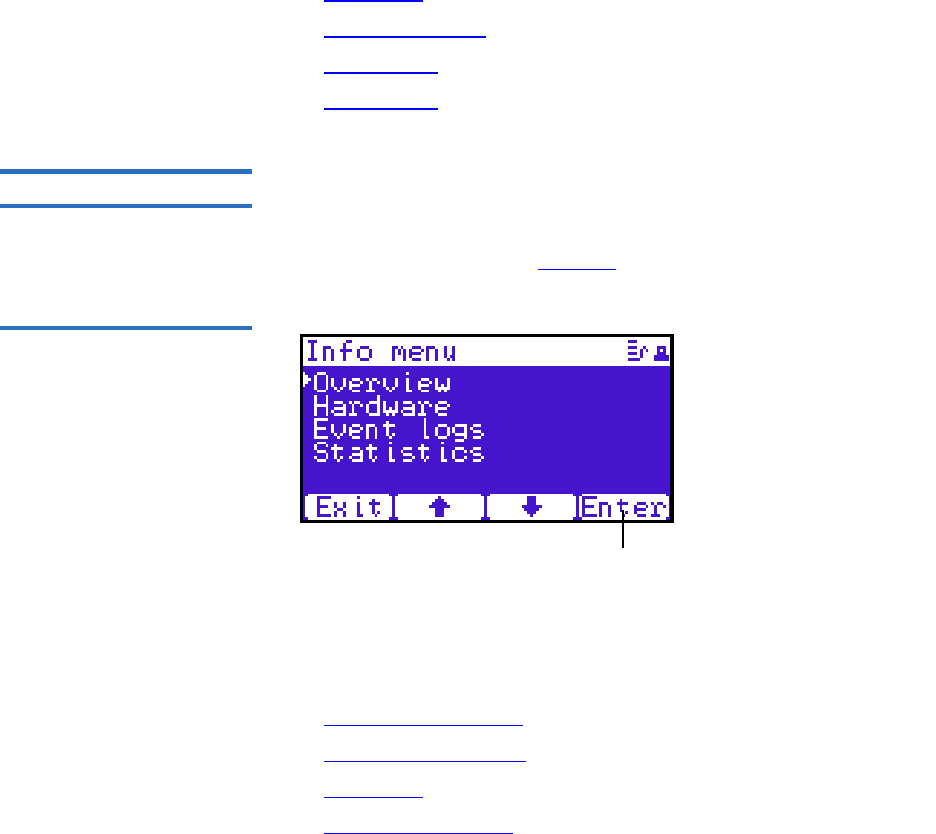
Chapter 2 Basic Library Operations
OCP Components
Quantum Scalar 50 User’s Guide 40
The following sections provide information on each function available
from the Quantum Scalar 50 OCP:
•Info Screen
•Operations Screen
•Setup Screen
•Diags Screen
Info Screen 2The Info screen provides access to library information such as hardware
status, event logs, and statistics.
To access the Info screen, press Info from the Home screen. The OCP
displays the Info screen (see figure 25):
Figure 25 Info Screen
Enter
The Info screen provides the following choices:
•Overview Information
•Hardware Information
•Event Logs
•Statistics Information

Chapter 2 Basic Library Operations
OCP Components
Quantum Scalar 50 User’s Guide 41
Overview Information 2
To view overview information:
1From the Info screen, use the up and down arrows to highlight
Overview and press Enter.
The Overview screen displays (see figure 26):
Figure 26 Overview Screen
The Overview screen displays the following information about the
library:
•Firmware revision
• Time and date the firmware was built
2Press Back or Next to review the network information such as the
current IP address, network mask, and gateway information.
3When you are finished viewing overview information, press Exit to
return to the Info screen.

Chapter 2 Basic Library Operations
OCP Components
Quantum Scalar 50 User’s Guide 42
Hardware Information 2
To view hardware information:
1From the Info screen, use the up and down arrows to highlight
Hardware and press Enter.
The Hardware screen displays (see figure 27):
Figure 27 Hardware Screen
Exit
The Hardware screen displays the following information (see
table 10):
Table 10 Hardware
Information Hardware
Information Description
System System information displays the overall sensor
details for the library.
Doors Door information displays the door sensor details.
Power Supply Power supply information displays the power
supply sensor details.
Robotics Robotics information displays the robotic sensor
details.
OCP OCP information displays the OCP sensor details.
Drives Drives information displays the tape drive sensor
details.
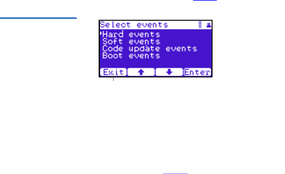
Chapter 2 Basic Library Operations
OCP Components
Quantum Scalar 50 User’s Guide 43
2Use the up and down arrows to highlight the information you wish
to display and press Enter.
3When you are finished viewing the hardware information, press Exit
to return to the Info screen.
Event Logs 2
To view the event logs:
1From the Info screen, use the up and down arrows to highlight Event
Logs and press Enter.
The Event Log screen displays (see figure 28).
Figure 28 Event Log Screen
Exit
2Use the up and down arrows to highlight the event type you wish to
view (Hardware, Software, Code updates, or Boot events).
The OCP displays the event severity list.
3Use the up and down arrows to highlight the severity type you wish
to view (All, Critical, Warning, and Informational).
The OCP displays the event or list of events in the specific severity
category. Use the Back and Next buttons to move between events.
4When you are finished viewing the event logs, press Exit to return to
the Info screen. Refer to chapter 4 on page 137 for detailed event
information.
Statistics Information 2
To view statistics information:

Chapter 2 Basic Library Operations
OCP Components
Quantum Scalar 50 User’s Guide 44
1From the Info screen, use the up and down arrows to highlight
Statistics and press Enter.
The Statistics screen displays (see figure 29):
Figure 29 Statistics Screen
Exit
The Statistics screen displays the following information about the
library:
• ElapsTm – seconds since boot.
• PCycles – total number of power cycles or reboots.
• SlotGet – count of cartridge retrievals from slots.
• SlotPut – count of cartridge deliveries to slots.
• SltRetG – count of retries in retrievals from slots.
• SltRetP – count of retries in deliveries to slots.
• DrvGet – count of cartridge retrievals from drives.
• DrvPut – count of cartridge deliveries to drives.
• DrvRetG – count of retries in retrievals from drives.
• DrvRetP – count of retries in deliveries to drives.
• DrvLdR – count of retries for cartridge loads in drives.
• DrvUnlR – count of retries for cartridge unloads in drives.
• XYmove – count of horizontal moves.
• Zmove – count of vertical moves.
• Pmove – count of extension moves.
• Rmove – count of rotation moves.

Chapter 2 Basic Library Operations
OCP Components
Quantum Scalar 50 User’s Guide 45
• XYretry – count of horizontal move retries.
• Zretry – count of vertical move retries.
• Pretry – count of extension move retries.
• Rretry – count of rotation move retries.
When you are finished viewing the statistics information, press Exit
to return to the Info screen.
Operations Screen 2The Operations (Ops) screen allows the user to view the status and issue
commands to the cabinet and tape drives.
To access the Operations screen, press Ops from the Home screen. The
OCP displays the Operations screen (see figure 30):
Figure 30 Operations Screen
Exit
The Ops screen provides the following choices:
•Library Operations
•Find Tape
•Move Tape
•Drive Operations
•Scan Inventory
Library Operations 2
To view library operations information:
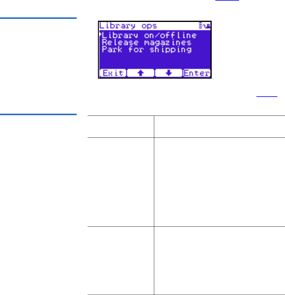
Chapter 2 Basic Library Operations
OCP Components
Quantum Scalar 50 User’s Guide 46
1From the Ops screen, use the up and down arrows to highlight
Library Operations and press Enter.
The Library Operations screen displays (see figure 31):
Figure 31 Library Operations
Screen
The following library operations options are available (see table 11):
Table 11 Library Operations
Options Library Operations
Options Description
Library on/offline When the cabinet is online, the library is ready
for host communication and for backup jobs
to proceed. When the cabinet is offline, the
host is no longer able to communicate with
the library. Self tests, diagnostics, and
inventory can only be performed when the
library is offline.
Use the up and down arrows to highlight
Library on/offline and press Enter to toggle the
library online or offline. Press Yes to confirm
the command or No to cancel.
Release magazines Use the up and down arrows to highlight
Release magazines and press Enter to view the
release magazines screen. Select the magazine
you wish to release and press Enter. Press Exit
to cancel.
Note: If there are no magazines installed or if
the magazines are configured as load ports,
this line will not display.
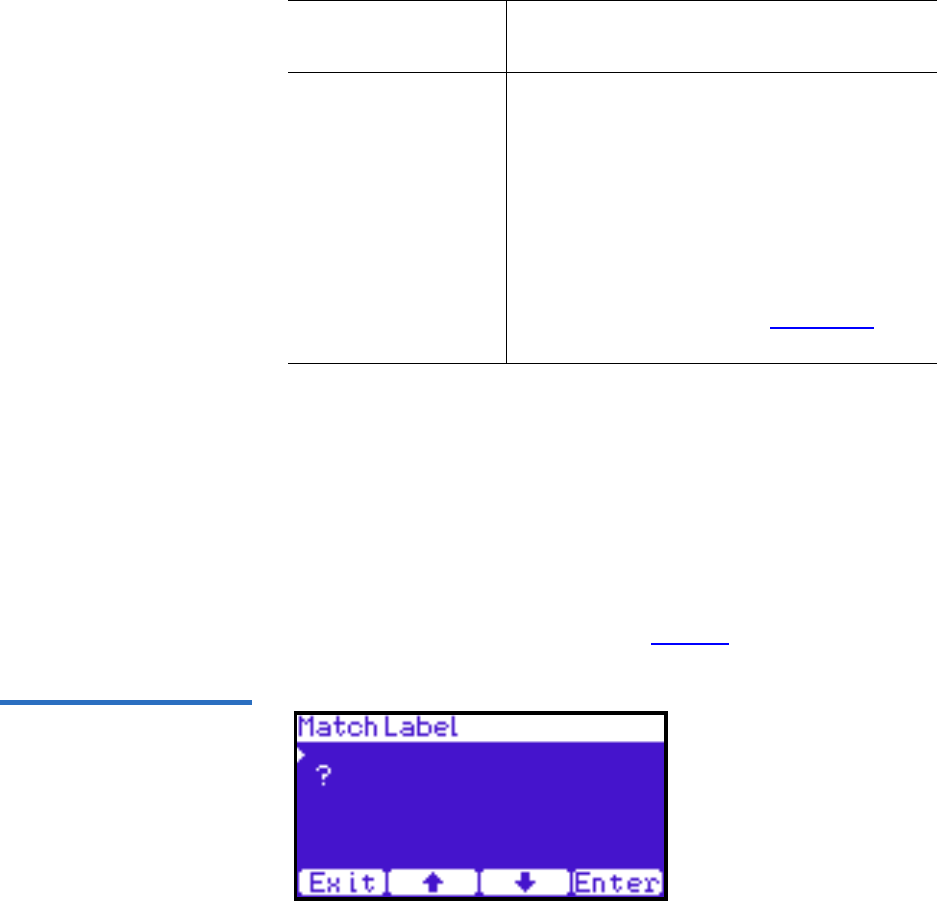
Chapter 2 Basic Library Operations
OCP Components
Quantum Scalar 50 User’s Guide 47
2When you are finished viewing the library operations information,
press Exit to return to the Ops screen.
Find Tape 2
To view media or tape cartridge information:
1From the Ops screen, use the up and down arrows to highlight Find
Tape and press Enter.
The Match Label screen displays (see figure 32):
Figure 32 Match Label Screen
2Use the up and down arrows to cycle through the alpha, numeric, or
wildcard (?) characters to enter the tape cartridge label. After each
character, press Enter.
Park for shipping Note: You must remove all tape cartridges
from the library prior to parking the library
robotics for shipment.
Use the up and down arrows to highlight Park
for shipping and press Enter to move the robot
to a safe position for transport. After the robot
is in it’s final position, the library shuts down.
After the library is shut down, you must
complete the repacking procedure before
transporting the library (see appendix D on
page 216).
Library Operations
Options Description
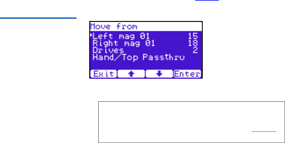
Chapter 2 Basic Library Operations
OCP Components
Quantum Scalar 50 User’s Guide 48
If a match is found, the cartridge type and location displays.
3If more than one match is found, a list of matching cartridges
displays. Select the tape cartridge from the list and press Enter.
The tape cartridge type and location displays.
Move Tape 2
To view the move tape screen:
1From the Ops screen, use the up and down arrows to highlight Move
Tape and press Enter.
The Move From screen displays (see figure 33):
Figure 33 Move From Screen
To move a tape cartridge within the library:
2Use the up and down arrows to select a magazine, tape drive, or fixed
slot group and press Enter.
The Move from screen displays a list of storage bins within the
selected magazine, tape drive, fixed slot group, and hand/top
passthru.
3Use the up and down arrows to select a tape cartridge from an
occupied bin and press Enter.
Note: If this is a master library in a multiple library stack, you
cannot move cartridges from one library into another. You
can only move cartridges manually from one library into
another via the remote management pages (see chapter 3
on page 63).
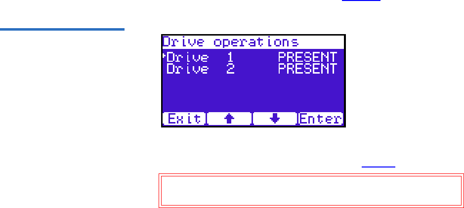
Chapter 2 Basic Library Operations
OCP Components
Quantum Scalar 50 User’s Guide 49
The Move to screen displays a list of magazine, tape drive, or fixed
slot groups.
4Use the up and down arrows to select a magazine, tape drive, or fixed
slot group to receive the cartridge and press Enter.
The Move to screen displays a list of storage elements within the
selected magazine, tape drive, or fixed slot group.
5Use the up and down arrows to select an empty bin to receive the
tape cartridge and press Enter.
The Move in progress screen displays. When the tape cartridge has
completed the move, a Success screen displays.
6When you are finished moving tape cartridges, press Exit to return to
the Ops screen.
Drive Operations 2
To perform a drive operation:
1From the Ops screen, use the up and down arrows to highlight Drive
Operations and press Enter.
The Drive Operations screen displays (see figure 34):
Figure 34 Drive Operations
Screen
1Use the up and down arrows to select a tape drive and press Enter.
The following drive options are available (see table 12):
Caution: Ensure that the tape drive does not contain a tape
cartridge prior to powering down the tape drive.

Chapter 2 Basic Library Operations
OCP Components
Quantum Scalar 50 User’s Guide 50
Table 12 Drive Options
2When you are finished viewing tape drive information, press Exit to
return to the Ops screen.
Scan Inventory 2
To perform an inventory of the library:
1From the Ops screen, use the up and down arrows to highlight Scan
Inventory and press Enter.
The Success screen displays. Press Done to complete.
Setup Screen 2The Setup screen allows the user to view or edit various library settings
such as date and time, network and host bus information.
To access the Setup screen, press Setup from the Home screen. The OCP
displays the Setup screen (see figure 30):
Device Options Description
Drive Pwr on This option powers on a specific tape drive
within the cabinet.
Pwr off This option shuts down a specific tape
drive within the cabinet in preparation for
tape drive removal.
Reset This option re initializes a specific tape
drive within the cabinet.
Drive Type Displays the tape drive type (DLT or LTO)
Serial
Number
Displays the tape drive serial number.
Firmware
Revision
Displays the tape drive firmware revision.
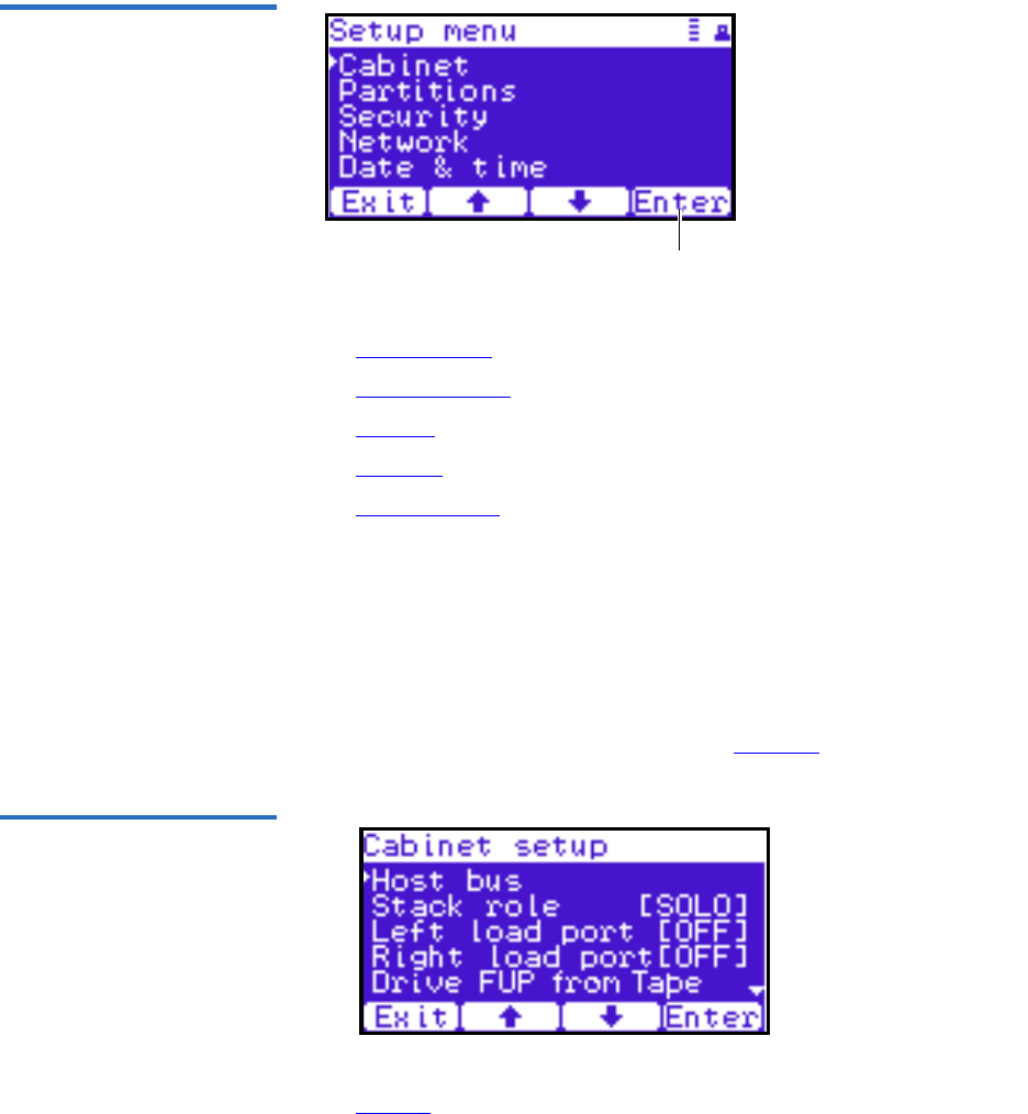
Chapter 2 Basic Library Operations
OCP Components
Quantum Scalar 50 User’s Guide 51
Figure 35 Setup Screen
Enter
The Setup screen provides the following choices:
•Cabinet Setup
•Partitions Setup
•Security
•Network
•Date and Time
Cabinet Setup 2
To view the cabinet setup screen:
1From the Setup screen, use the up and down arrows to highlight
Cabinet Setup and press Enter.
The Cabinet Setup screen displays (see figure 36):
Figure 36 Cabinet Setup
Screen
The Cabinet Setup screen displays the following options (see
table 13):

Chapter 2 Basic Library Operations
OCP Components
Quantum Scalar 50 User’s Guide 52
Table 13 Cabinet Setup
2When you are finished viewing the cabinet setup information, press
Exit to return to the Setup screen.
Partitions Setup 2
To view or edit the partition information:
Cabinet Setup Description
Host bus Select the host bus option to view or edit the SCSI
IDs for the changer (library) and tape drives. The
Host bus option also allows you to set the Fibre
Channel settings for any Fibre Channel tape drives
installed. Loop ID, topology, and speed for each tape
drive can be set.
NOTE: SAS tape drives do not require a SCSI ID and
cannot be configured. Use the default tape drive
configuration information.
Stack role Select the stack role option to view or set the library
stack role (stand alone, master, or slave).
Left load port Select the left load port options to enable/disable the
left load port and also to designate one column or the
entire magazine as a load port.
Right load port Select the right load port options to enable/disable
the right load port and also to designate one column
or the entire magazine as a load port.
Drive FUP
from tape
Select the magazine or fixed that contains the
firmware update cartridge (FUP) and then the
specific tape drive to update. The library must be
offline to update the tape drive firmware.
Full Inventory When full inventory is on, the library will complete a
full inventory of the tape cartridges whenever a door
is opened. When full inventory is off and a load port
is accessed, the library will only inventory the load
port and not the entire library.
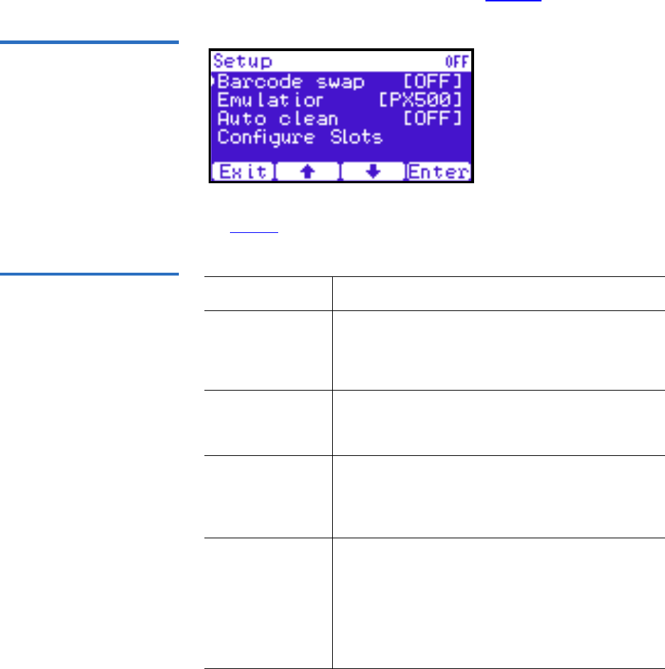
Chapter 2 Basic Library Operations
OCP Components
Quantum Scalar 50 User’s Guide 53
1From the Setup screen, use the up and down arrows to highlight
Partitions and press Enter.
The Partitions Setup screen displays (see figure 37):
Figure 37 Partitions Setup
Screen
The Partitions Setup screen displays the following options (see
table 14):
Table 14 Partitions Setup Partitions Setup Description
Barcode swap Select the barcode swap to change the barcode
swap option (enable/disable). When enabled, the
media type prefix is swapped from the back of
barcode to the beginning.
Emulation Select the emulation option to change the library
emulation mode. Emulation options are: Scalar 50,
PX500, or P2000.
Auto clean Select the auto clean option to change the library
autoclean mode (enable/disable). When enabled,
the library will automatically load a cleaning
cartridge when a tape drive requests a cleaning.
Configure Slots The configured slots option allows you to
designate the number of slots available and
reported to the host. Use the up and down arrows
to highlight Configure Slots and press Enter. Enter
the number of configured slots and press Enter.
The library will reconfigure with the new slot
count.
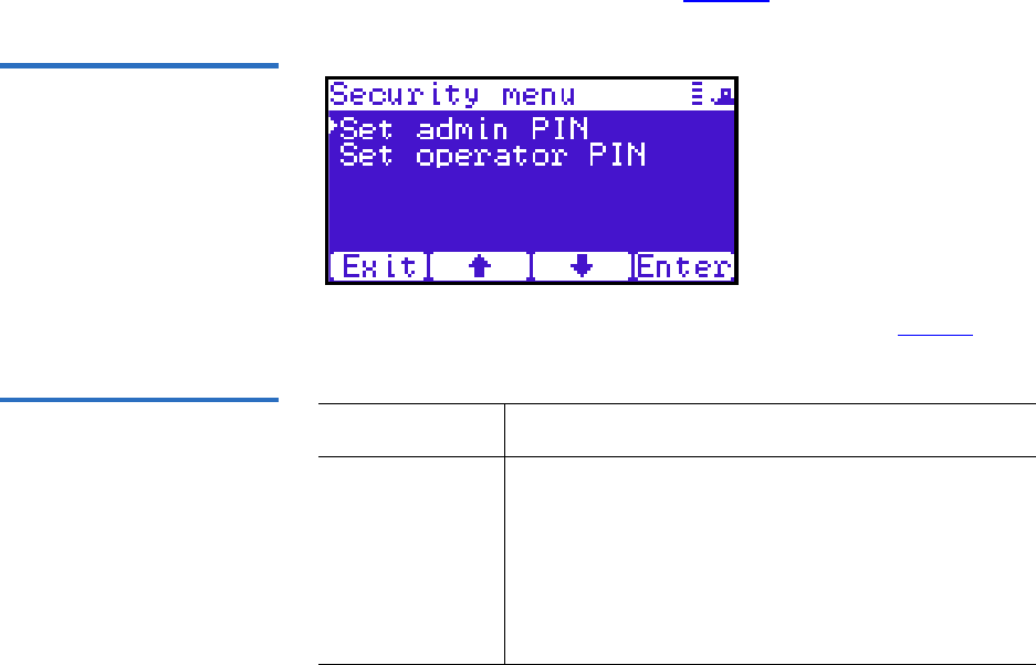
Chapter 2 Basic Library Operations
OCP Components
Quantum Scalar 50 User’s Guide 54
2When you are finished viewing/editing the library setup
information, press Exit to return to the Setup screen.
Security 2
To view or edit the security information:
1From the Setup screen, use the up and down arrows to highlight
Security and press Enter.
The Security screen displays (see figure 38):
Figure 38 Security Screen
The Security screen displays the following options (see table 15):
Table 15 Security Setup Security Setup Description
Set admin PIN The admin PIN allows access to all areas of the
OCP. Select Set admin PIN and use the up and down
arrows to cycle through the PIN numbers. Press
Enter to accept each digit and press Enter twice after
the last digit of the PIN. You must verify the PIN
number. The admin PIN can be 0 to 8 characters
long, numbers only.
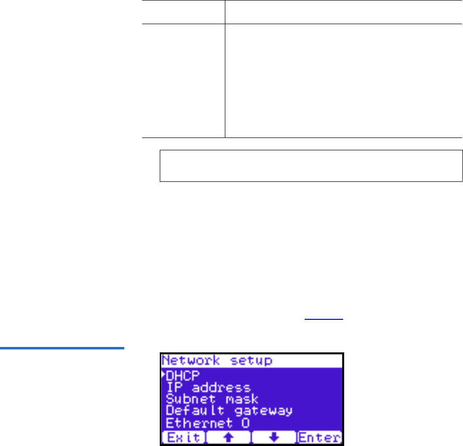
Chapter 2 Basic Library Operations
OCP Components
Quantum Scalar 50 User’s Guide 55
2When you are finished viewing/editing the security setup
information, press Exit to return to the Setup screen.
Network 2
To view or edit the network information:
1From the Setup screen, use the up and down arrows to highlight
Network and press Enter.
The Network screen displays (see figure 39):
Figure 39 Network Screen
Set operator
PIN
The operator PIN only allows access to the Info or
Ops menus of the OCP. The operator cannot change
any library settings. Select Set operator PIN to set
the operator PIN. use the up and down arrows to
cycle through the PIN numbers. Press Enter to
accept each digit and press Enter twice after the last
digit of the PIN. You must verify the PIN number.
The operator PIN can be 0 to 8 characters long,
numbers only.
Note: OCP passwords are independent of the remote
management passwords.
Security Setup Description

Chapter 2 Basic Library Operations
OCP Components
Quantum Scalar 50 User’s Guide 56
The Network screen allows you to view or edit the following network
settings:
•DHCP (default setting)
•IP address
•Subnet mask
• Default gateway
•Ethernet 0
2Use the up and down arrows to select the network setting you wish
to view or edit and press Enter.
aTo enable/disable DHCP, press Yes to enable DHCP or No to
disable DHCP. If your library is not connected to a network
which uses a DHCP server to assign IP information, disable this
function.
bTo set the IP address, subnet mask, and gateway, use the up and
down arrows to select the appropriate number and press Enter to
accept.
3When you are finished viewing/editing the network information,
press Exit to return to the Setup screen.
Date and Time 2
To view or edit the date and time information:
1From the Setup screen, use the up and down arrows to highlight Date
and Time and press Enter.
The Date and Time screen displays (see figure 40):
Note: The network settings (IP address, subnet mask, and
default gateway) are only active when DHCP is disabled.
Note: For the network information such as the IP address to be
active, the library must reboot. To reboot the library, see
“Reboot Library” on page 126.
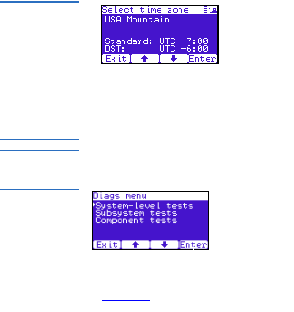
Chapter 2 Basic Library Operations
OCP Components
Quantum Scalar 50 User’s Guide 57
Figure 40 Date and Time
Screen
2Use the up and down arrows to view or edit the date and time
information. Press Enter to advance to the next choice. After you have
edited the final setting (seconds), press Save to accept the new
settings.
3When you are finished viewing/editing the date and time
information, press Exit to return to the Setup screen.
Diags Screen 2The Diagnostics screen allows the user to perform diagnostic tests on the
library.
To access the Diagnostics screen, press Diags from the Home screen. The
OCP displays the Diagnostics screen (see figure 41):
Figure 41 Diagnostic Screen
Enter
The Diagnostics screen provides the following choices:
•System-level Tests
•Component Tests
•Subsystem Tests

Chapter 2 Basic Library Operations
OCP Components
Quantum Scalar 50 User’s Guide 58
System-level Tests 2
To execute a system-level test:
1From the Diags screen, use the up and down arrows to highlight
System-level Test and press Enter.
The System-level Test screen displays (see figure 42):
Figure 42 System-level Test
Screen
The System-level Test screen provides the following diagnostic tests:
•Health test
•Self tests
• Calibration stats
• Random Load/Unload
• Random (Slots Only)
•Random (Drive Focus)
• Sequential bins
• Sequential drives
2Use the up and down arrows to select the system test and press Enter
to execute.
3When you are finished executing system-level tests, press Exit to
return to the Diags screen.
Subsystem Tests 2
To execute a subsystem test:
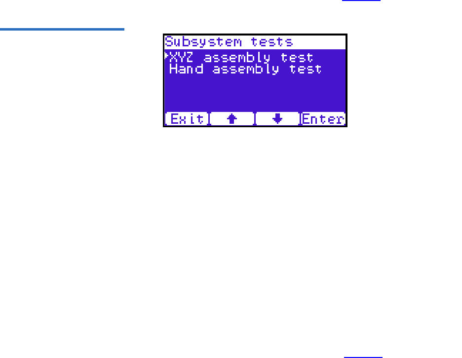
Chapter 2 Basic Library Operations
OCP Components
Quantum Scalar 50 User’s Guide 59
1From the Diags screen, use the up and down arrows to highlight
Subsystem Tests and press Enter.
The Subsystem Tests screen displays (see figure 43):
Figure 43 Subsystem Tests
Screen
The Subsystem Tests screen provides the following diagnostic tests:
• XYZ assembly test
• Hand assembly test
2Use the up and down arrows to select the subsystem test and press
Enter to execute.
3When you are finished executing subsystem tests, press Exit to return
to the Diags screen.
Component Tests 2
To execute a component test:
1From the Diags screen, use the up and down arrows to highlight
Component Tests and press Enter.
The Component Tests screen displays (see figure 44):
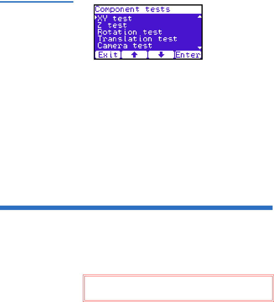
Chapter 2 Basic Library Operations
Load Port Configuration
Quantum Scalar 50 User’s Guide 60
Figure 44 Component Tests
Screen
The Component test screen provides the following diagnostic tests:
• XY test
•Y tests
• Rotation stats
• Translation test
• Camera test
• Temperature test
• Home position
2Use the up and down arrows to select the component test and press
Enter to execute.
3When you are finished executing component tests, press Exit to
return to the Diags screen.
Load Port Configuration
Load ports are used to import or export tape cartridges from the library.
When configured as a load port, your backup application will
automatically use these bins when exporting or importing tape
cartridges. The bottom left and right magazines in each library can be
configured to provide the following load port elements:
Caution: When placing tape cartridges in the load port slots, ensure
that the tape cartridges are completely in the slot before
sliding the magazine back into the library.

Chapter 2 Basic Library Operations
Load Port Configuration
Quantum Scalar 50 User’s Guide 61
• Single column load port (5 slots SDLT/6 slots LTO)
• Magazine load port (15 slots SDLT/18 Slots LTO)
Tech Tip: Deciding between a single column and an entire
magazines as a load port depends on the amount of tape
cartridges you typically import/export from the library. If
you generally import or export small numbers of tape
cartridges to and from the library, a single column should
be sufficient. If you import or export large numbers of
tape cartridges, an entire magazine as a load port would
be beneficial.
Each of the load ports are configured independently so that one load port
can be configured as a column and the other load port can be configured
as a column or as a magazine.
When set for a single column load port, the magazine is physically
restricted to allow access to the first column in the magazine only.
When set for a 15-slot load port, the entire magazine can be removed (the
same for a 18-slot LTO magazine).
The load port option is set using the operator control panel Setup menu.
The settings are listed in table 16 and illustrated in figure 45.
Table 16 Import/Export Option
Settings Setting Manual Access SCSI Element
None None Storage element
Single column Single column Import/Export element
Magazine Entire magazine Import/Export element
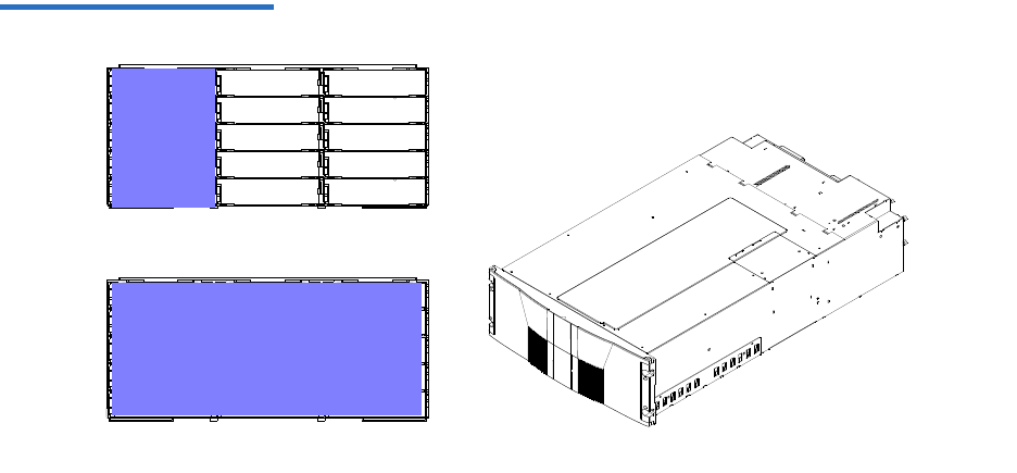
Chapter 2 Basic Library Operations
Load Port Configuration
Quantum Scalar 50 User’s Guide 62
Figure 45 Load Port Settings
Single column load port
Full magazine load port
Mag 1 Mag 1
Enabling load ports will reduce the number of storage elements in the
library. For example, if the library is set to the default capacity (left
magazine only) and a single column is set aside as a load port, the storage
capacity is reduced by the number of slots in that first column. The
number of storage slots would be reduced by five for an SDLT magazine
and six slots in a LTO magazine.

Quantum Scalar 50 User’s Guide 63
Chapter 3
3Quantum Scalar 50 Remote
Management
The Quantum Scalar 50 library utilizes a web-based interface which
allows you to configure and manage the library from a remote
workstation on the same network. The Quantum Scalar 50 library is
managed through the following web pages (accessible using Internet
browser software installed on the host computer):
•Status allows you to view the following: hardware status, event logs,
and statistics
•Operations allows you to perform cabinet operations remotely such
as cartridge movement and inventory requests and drive operations
•Setup allows you to setup cabinet identification, user information,
SCSI IDs, network information, events, date and time information,
partitioning, secure tape, and tape encryption information.
•Utilities allows the user to run cabinet utilities remotely.
•Reference links to related sites.
•Logout allows the user to log out of the library remote management
pages.

Chapter 3 Quantum Scalar 50 Remote Management
Quantum Scalar 50 Web Pages
Quantum Scalar 50 User’s Guide 64
Quantum Scalar 50 Web Pages
The internet browser software is not supplied with the Quantum Scalar
50 library; you must obtain and install it independently. The Quantum
Scalar 50 library supports the following internet browsers:
• Microsoft Internet Explorer 6.1 or later
You can download this software from
http://www.microsoft.com.
• Mozilla Suite 1.7 on Solaris 10
You can download this software from
http://www.mozilla.org
• Firefox 1.0.6 on Windows
You can download this software from
http://www.mozilla.org
• Java Plug-in 1.4.2 or later
You can download this software from
http://www.java.com
Quantum Scalar Web
Page Menu Items 3The following figures depict the menu items available from the Quantum
Scalar 50 Web Pages:
•Figure 46 provides the default menus for the Scalar 50 web pages
•Figure 47 provides an additional menu for the tape security feature
available with the DLT-S4 tape drives. When this feature is enabled,
the menu will display as part of the Setup page.
Note: To optimize performance, all browsers should have both
cookies and pop-ups enabled. This allows the refresh activities
of the remote management web pages to work appropriately.
Java 1.4.2 or above available from http://www.java.com
should also be installed to support applets that automatically
refresh pages and display pop-ups for warnings and critical
events.

Chapter 3 Quantum Scalar 50 Remote Management
Quantum Scalar 50 Web Pages
Quantum Scalar 50 User’s Guide 65
Figure 46 Quantum Scalar 50
Web Page Menu Items
Setup Logout
Setup Cont.
Identification
Library Information
Model
Serial Number
Library Name
Contract Number
Location
Description
Position
Business Inform.
Company
Address
Users
Users List
SCSI/Fibre
Cabinet
Device
SCSI ID
LUN
Vendor
Model
Serial Number
Revision
Connectivity
Remove Users
User Information
Full Name
User Name
Password
Network
Network Infor.
Hostname Field Service
Setup Wizard
Library Offline
Date and Time
Configuring Devices
Configuring Load Ports
Configuring Partition
Setup Wizard Complete
Domain
IP Address
Default Mask
Obtain DHCP
Email server Infor.
From:
Email server
Primary DNS
Secondary DNS
Verify password
User Name
Assign Role
Operator
Administrator
Address
Phone
Fax
Pager
Email
Add to Event List
Status
Overview
Date and Time
Model number
Software Version
Hardware Status
Event Log
Cabinet
Serial number
Power Supply
SCB temp.
View Events
From: date/time
To: date/time
Category
Cabinet
All errors
Cabinet #
Hard errors
Soft errors
Update errors
Boot errors
Doors
Left mag. door
Right mag. door
BackPlane status
Drives
Drive #
Drive present
Drive serial #
State
Drive Activity
Drive Status
Drive Power
Drive Reg. tmp
Drive fan RPM
BackPlane temp.
System power...
SCB volt. (1.2v)
SCB volt. (1.8v)
SCB volt. (2.5v)
SCB volt. (3.3v)
SCB volt. (5.0v)
cPCI card (12v)
OCP
OCP status
OCP temp.
Library Statistics
Cabinet #
Power on time
# of power cycles
# slot/port gets
# slot/port puts
# slot/port get retries
# drive get retries
# drive put retries
# drive load retries
# drive unload retries
# XY motor moves
# Z motor moves
# slot/port put retries
# drive gets
# drive puts
# picker moves
# rot. motor moves
# XY motor retries
# Z motor retries
# picker retries
# rot. motor retries
Power Supply #
Pwr sply pres.
Pwr sply (24v)
Fan sp. (RPM)
Events
Email
Message Type
Library
Library Config.
Load ports (L/R)
Partitions
Partition List
Remove All
Partition Config.
Name
Cabinets
Magazines
Drives
Load Ports
Surrogate Drive
Partion Options
Configured Slots
Recipients
Non-recipients
E-mail
Send test
SNMP
Comm. Names
Trap Dest.
Critical
Warning
Informational
Event Types
Critical
Warning
Informational
Date and Time
Date
Time
Current time
Time zone
Auto adjust.
En. Auto Cln.
Em. P-Series
En. Bar. Swap
Em.Scalar 50
Operations
Find
Find Barcode
Find Media
Logical Map
Physical Map
Inventory
Partition
Logical Map
Physical Map
Move
Source
Logical Map
Physical Map
Partition
Utilities
Library
Online/Offline
Reboot Library
Fib. Bridge Rescan
System Tests
Health Test
Select Cabinet
Start Test
Maintenance
Conf. Files
Upload Firmware
Action
Cabinet
Browse
Upload Drive Image
Drive Type
Drive Number
Cabinet
Browse
Browse
Logs
Tasks
Drive Log
View Log
FA Log
Retrieve
Cabinet
System Tests
Test Type
Action
Previous Results
Lib. Level Tests
Sys. Level Tests
Health Tests
Sub-Sys. Tests
Comp. Tests
Partition
Cabinet
Runs
Start Test
Continuous
Park for Shipping
Partition
Element
Position
Destination
Partition
Element
Position
Drives
Drive Operations
Logical Map
Physical Map
Partition
Action
Pwr Off
Pwr On
Reset
Drive #
Reference
Links
About
Library Information
Model
Software Version
Serial Number
IEEE ID
MAC Address
IP Address
Subnet Mask
Default Gateway
IEEE ID
MAC Address
Cabinet Information
Cabinet
Slots
Drives
Load Ports
Serial Number
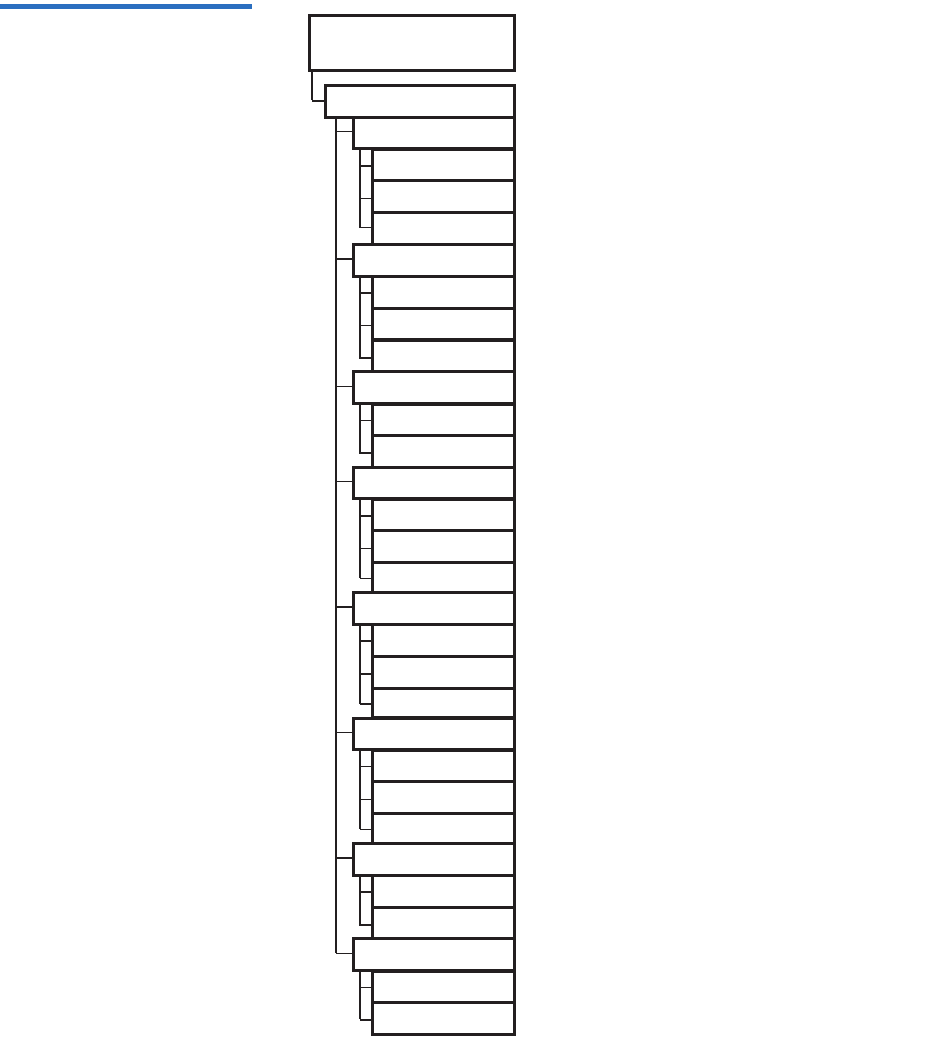
Chapter 3 Quantum Scalar 50 Remote Management
Quantum Scalar 50 Web Pages
Quantum Scalar 50 User’s Guide 66
Figure 47 Quantum Tape
Security and Tape Encryption
Menus
Setup
Secure Key
Protection Mode
Never write...
Only write...
Write to all...
Enable/Disable...
Enable all drives
Disable all drives
Select drives
Select Secure Key
Sec. Key Name
Date Created
Assign Secure Key
Find Sec. Cart.
Sec. Name, Date
Barcode
Create Secure Key
Sec. Key Name
Verify Sec. Key
Secure Key
Delete Secure Key
Unused Keys
Active Keys
Inactive Keys
Upload Secure Key
Encryption Key
File Name
Backup Secure Key
Encryption Key
Verify Encr. Key
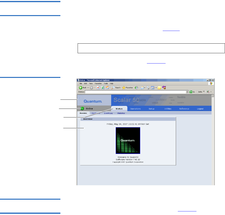
Chapter 3 Quantum Scalar 50 Remote Management
Quantum Scalar 50 Web Pages
Quantum Scalar 50 User’s Guide 67
Accessing Scalar 50 Web
Pages 3To access the Quantum Scalar 50 web pages:
1On the host computer, open the internet browser software.
2In the Address field, type http://IPaddress/ where IP address is the IP
address for the Quantum Scalar 50. (see “Setup” on page 84).
3Enter the username and password and click OK.
The Overview page displays (see figure 48):
Figure 48 Overview Page
Content area
Navigation area
Quick status
Banner area
Using the Quantum Scalar
50 Web Pages 3The first page that displays when you access the Quantum Scalar 50 web
pages is the Quantum Scalar 50 Overview page (see figure 48). This page
includes information on the Quantum Scalar 50 such as library name,
date and time, and includes a dynamic graphic which changes colors
depending on the library health.
Note: The default username and password is admin.
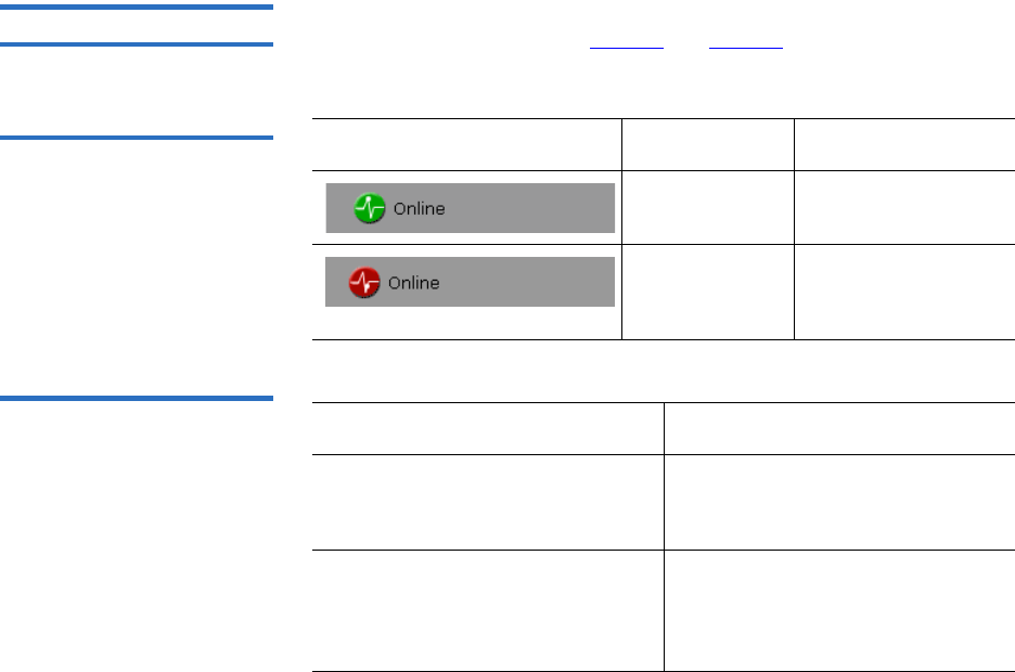
Chapter 3 Quantum Scalar 50 Remote Management
Quantum Scalar 50 Web Pages
Quantum Scalar 50 User’s Guide 68
The Overview page is divided into five distinct sections:
• Banner
• Quick status
• Navigation area
• Content area
The banner frame displays the corporate logo and product name. The
contents frame displays a list of the Quantum Scalar 50 web pages. To
view a page, click its corresponding link. The management frame
displays the page you selected.
To return to a previous web page, click the browser’s Back button.
Quick Status 3The Quick Status icon provides the current health status for the library.
Refer to the following tables (table 17 and table 18) for quick status library
health conditions.
Table 17 Quick Status Library
Health Conditions
Table 18 Quick Status Health
Messages
Quick Status Icon Library Health Description
Library health:
OK.
The library health is
OK.
Library health:
Critical
The library health is
in a Critical state
(needs attention)
Quick Status Messages Description
Online and Offline These messages indicate the
current availability status of the
library.
Init Error The library has failed to initialize.
Review the hardware status page
and contact Quantum Customer
Support if necessary.

Chapter 3 Quantum Scalar 50 Remote Management
Quantum Scalar 50 Web Pages
Quantum Scalar 50 User’s Guide 69
Stopped The hand has stopped. Check the
error log and contact Quantum
Customer Support if necessary.
Door Open A library door is open.
Tape Cleaning A tape drive is being cleaned.
Moving A tape cartridge is being moved.
Code Update The library is in the process of
upgrading the system code. Wait
until the process is complete
Initializing The library is in the process of
coming online. Wait until the
library becomes online.
Power Down The library is powering down.
Wait for the unit to shutdown.
Communication Down The library is in the process of
shutting down. Library
communication will resume
when the library powers on.
Over Temp The library has exceeded the
maximum temperature threshold.
Review the hardware status page
and contact Quantum Customer
Support if necessary.
Diagnostic The library is executing a
diagnostic test. Wait for the test to
complete.
Quick Status Messages Description
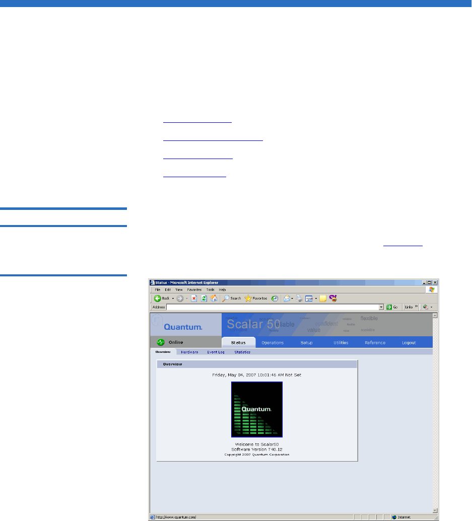
Chapter 3 Quantum Scalar 50 Remote Management
Status
Quantum Scalar 50 User’s Guide 70
Status
The Status page displays the general status or health of the library as well
as specific hardware status. The page also provides access to event logs as
well as library statistics.
The Status page is divided into the following sections:
•Overview Page
•Hardware Status Page
•Event Log Page
•Statistics Page
Overview Page 3To access the Overview page, from any page, click Status from the
navigation bar.
The management frame displays the Status page (see figure 49).
Figure 49 Status Page
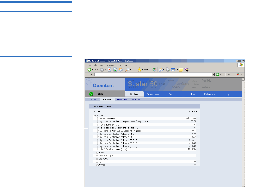
Chapter 3 Quantum Scalar 50 Remote Management
Status
Quantum Scalar 50 User’s Guide 71
Hardware Status Page 3The Hardware status page displays the library component status within
the library.
To access the Hardware page, from the Status page, click on the Hardware
tab at the top of the page.
The Hardware Status page displays (see figure 50):
Figure 50 Hardware Status
Page
Hardware
components
Library components within the library are displayed in a tree-like
fashion. A red background indicates critical or failed condition. Related
values or error messages are listed under details.
To view the status of a library component
1Click on a plus sign to expand a branch and display the status of
related subcomponents. Click on a minus sign to collapse a branch.
Click Expand All/Collapse All to expand or collapse all branches.
Some components, such as drives, are displayed as a link. Clicking on
the link will open a detail window displaying all data related to the
component.
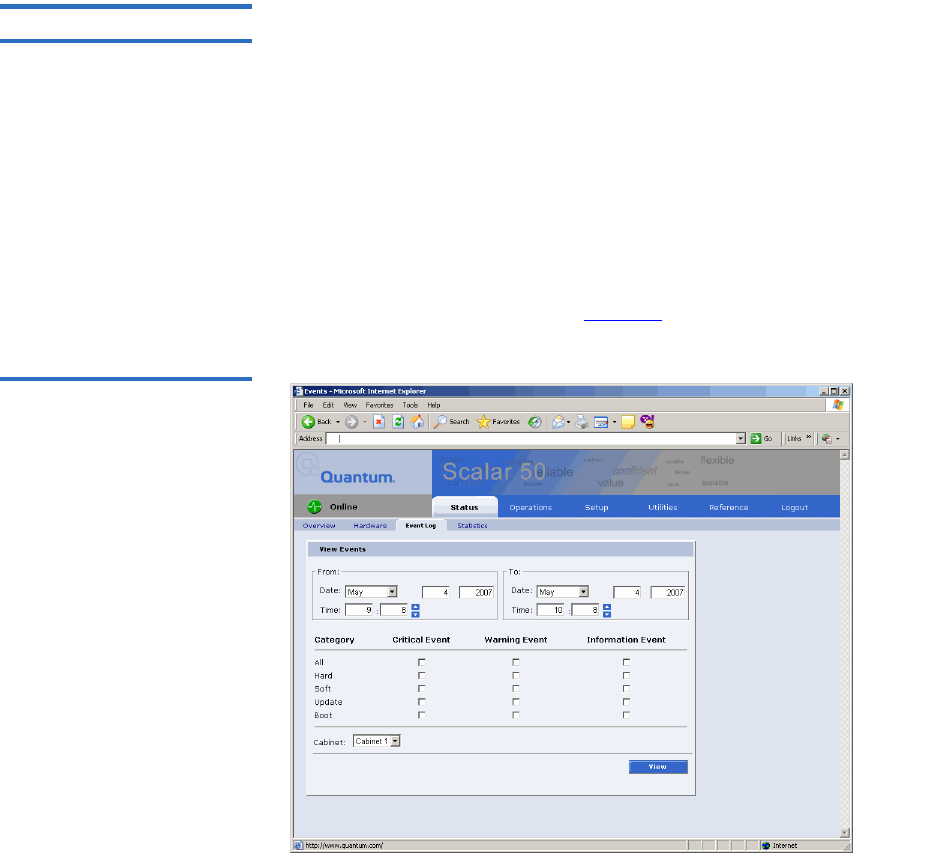
Chapter 3 Quantum Scalar 50 Remote Management
Status
Quantum Scalar 50 User’s Guide 72
Event Log Page 3The Event Log page allows the user to view events that occur on the
library. These events are divided into the following categories:
• All - views all events in all categories
• Hard - views only hardware related events
• Soft - views only software related events
• Update - views only events related to library update functions
• Boot - views only events related to library boot sequence
To access the Event Log page, from the Status page, click on the Event Log
tab at the top of the page.
The Event Log page displays (see figure 51):
Figure 51 Event Log Page

Chapter 3 Quantum Scalar 50 Remote Management
Status
Quantum Scalar 50 User’s Guide 73
To view an Event Log:
1In the Event Log page, change the From and To areas to reflect the
time range of the event log you wish to view. Click the up and down
arrows to change the hour and/or minute values by increments of
one. Double-clicking will increment or decrement the value by 5. You
may also type in a valid hour (0 - 24) or minute (0 - 59).
2Select desired categories and priority levels (critical, warning, or
informational) for the event list.
3Click View to display the list.
A smaller window displays the information matching the range,
category, and priority specified.
Statistics Page 3The Statistics page allows the user to view library statistics for the entire
library or certain components within the library.
The following table shows the statistics available from the Statistics page:
Note: The default date/time range is one hour prior to the
current time and day.
Note: Search time will vary depending on the time range
entered.

Chapter 3 Quantum Scalar 50 Remote Management
Status
Quantum Scalar 50 User’s Guide 74
Table 19 Statistics Information Cabinet or Component Statistical Information
Cabinet (library) Time since last power-on (seconds)
Time processing robot commands
(seconds)
Estimated number of power cycles
Attempted slot/port picks
Attempted slot/port places
Attempted drive picks
Attempted drive places
Number of individual horizontal moves
Number of individual vertical moves
Number of individual extension moves
Number of individual hand moves
Number of individual depth moves
Number of individual rotary moves
Number of horizontal retries
Number of vertical retries

Chapter 3 Quantum Scalar 50 Remote Management
Status
Quantum Scalar 50 User’s Guide 75
To access the Statistics page, from the Status page, click on the Statistics
tab at the top of the page.
The Statistics page displays (see figure 52):
Number of extension retries
Number of hand retries
Number of depth retries
Number of rotary retries
Number of drive place retries
Number of drive pick retries
Number of partially gripped cartridge
retries
Number of drive load retries
Number of barcode scan retries
Number of slot/port pick retries
Number of slot/port place retries
Cabinet or Component Statistical Information
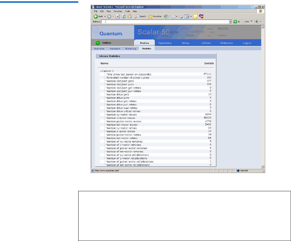
Chapter 3 Quantum Scalar 50 Remote Management
Status
Quantum Scalar 50 User’s Guide 76
Figure 52 Statistics Page
Note: Statistics for individual elements (a specific drive, slot, or port) are
included in the element detail window and can be viewed by
clicking on a drive, slot, or port link from zoom windows accessed
via the Operations pages. The zoom windows are opened by
clicking on the panel or cluster name from physical or logical
maps.

Chapter 3 Quantum Scalar 50 Remote Management
Operations
Quantum Scalar 50 User’s Guide 77
Operations
The Operations page is divided into the following sections:
•Find Page
•Move Page
•Inventory Page
•Drives Page
Accessing the
Operations Page 3To access the Operations page, click Operations from the contents frame.
The management frame displays the Operations page (see figure 53).
Figure 53 Operations Page
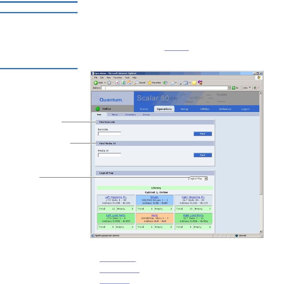
Chapter 3 Quantum Scalar 50 Remote Management
Operations
Quantum Scalar 50 User’s Guide 78
Find Page 3The Find page allows the user to find and locate specific barcodes within
the library as well as view the library contents (slots, ports, drives, hand,
or address).
To access the Find page, from the Operations page, click on the Find tab at
the top of the page.
The Find page displays (see figure 54):
Figure 54 Find Page
Find barcode
Find Media ID
Select physical/logical
map
The Find page is divided into the following sections:
•Find Barcode
•Find Media ID
•Select Map

Chapter 3 Quantum Scalar 50 Remote Management
Operations
Quantum Scalar 50 User’s Guide 79
Find Barcode 3
The find barcode section allows the user to find a specific barcode (or
partial barcode) within the library and view its location.
To find a barcode or partial barcode:
1Enter a barcode, or partial barcode with wildcards (*,?) in the barcode
field.
2Click Find.
A separate window displays the barcode(s) sharing the barcode
string entered in the barcode field. Click the individual barcode label
to display the corresponding cartridge detail page.
Find Media ID 3
The show contents section allows the user to locate a specific media ID
within the library (slots, ports, drives, hand, or address)
To find a media ID:
1Enter a media ID, or partial ID with wildcards (*, ?) in the Media ID
field.
2Click Find.
A separate window displays the media ID(s) sharing the string
entered in the media ID field. Click the individual barcode label to
display the corresponding cartridge detail page.
Note: Leaving the barcode field empty will result in listing all
barcode labels within the library.
Note: Leaving the media ID field empty will result in listing all
barcode labels within the library.

Chapter 3 Quantum Scalar 50 Remote Management
Operations
Quantum Scalar 50 User’s Guide 80
Select Map 3
The select map section allows the user to view the library in either a
physical or logical view. To toggle between physical and logical map,
click the Physical/Logical Map button in the map section.
Physical Map: A physical view displays a high level physical
representation of the library. Slots, magazines, drives, and fixed slots are
displayed as a panel located on either the left, rear, or right wall of the
library. Clicking on the panel name opens a zoom view of the panel (i.e.
similar to pulling out a loadport or drawer) displaying all elements (slots,
ports, or drives) in a spreadsheet format.
Logical Map: A logical map displays slots, magazines, drives, and fixed
slots. Clicking on the panel name opens a zoom view of the panel (i.e.
similar to pulling out a loadport or drawer) displaying all elements (slots,
ports, or drives) in a spreadsheet format. From the zoom view, clicking
on an element opens a detail window.
Move Page 3The Move page allows the user to move a single cartridge from a source
(slot, port, drive, or address) to a destination (slot, port, drive, or
address).
To access the Move page, from the Operations page, click on the Move tab
at the top of the page.
The Move page displays (see figure 55):
Note: The Physical/Logical Map information is displayed at the
bottom of each Operations page.
Note: The physical map may show gaps in the element numbering
depending on the load port configuration.
Note: Under the Logical Map view, an option to print the view to a
local printer is available by clicking on the Print View link
located in the upper left-hand corner of the Logical Map
section.
Note: The library must be off-line to move a cartridge.
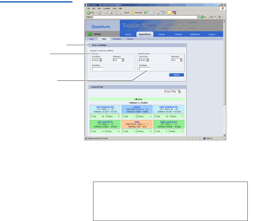
Chapter 3 Quantum Scalar 50 Remote Management
Operations
Quantum Scalar 50 User’s Guide 81
Figure 55 Move Page
Destination
Source
Move cartridge
To move a cartridge:
1Select a cabinet, source element (slot, drive, address, or hand), and
enter a starting position and count. If the count field is left empty,
only the starting cartridge is moved.
2Select a destination cabinet, element, and position. If more than one
cartridge is moved, the position entered in as a destination is the first
one filled, consecutive elements must be empty.
Note: The hand is the robotic gripper used to move
cartridges in the library. If the library is in a
stacked environment with other Scalar 50
libraries, the pass-thru slot is available as a source
element.
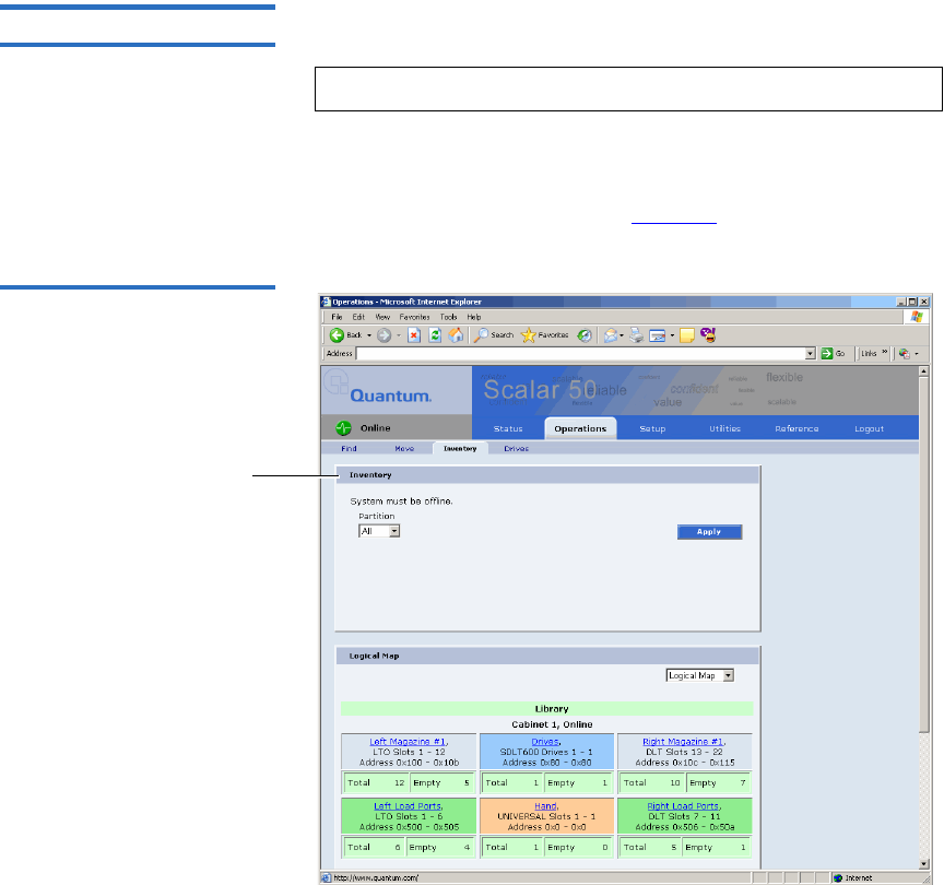
Chapter 3 Quantum Scalar 50 Remote Management
Operations
Quantum Scalar 50 User’s Guide 82
Inventory Page 3The Inventory page allows the user to perform an inventory on all
elements within the library or specific element ranges.
To access the Inventory page, from the Operations page, click on
the Inventory tab at the top of the page.
The Inventory page displays (see figure 56):
Figure 56 Inventory
Page
Inventory
To perform an inventory:
1Select the cabinet or library to inventory.
2Click Apply to perform the inventory.
The progress of the inventory displays in a separate window.
Note: The library must be off-line to perform an inventory.
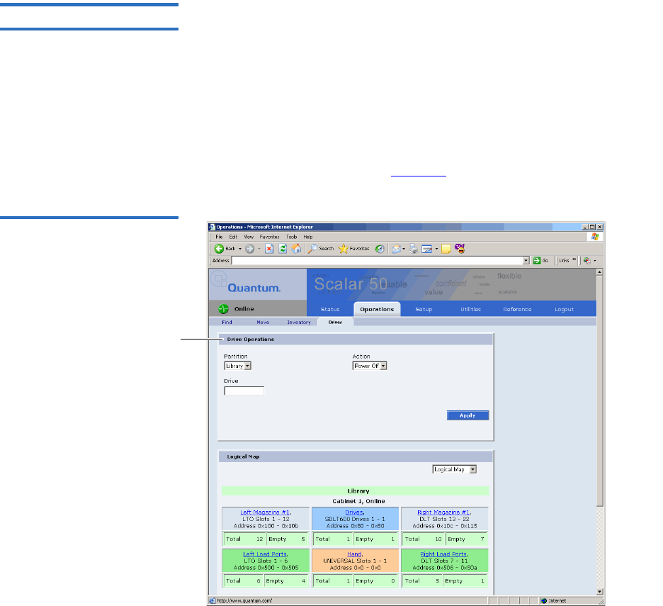
Chapter 3 Quantum Scalar 50 Remote Management
Operations
Quantum Scalar 50 User’s Guide 83
Drives Page 3The Drives page allows the user to perform the following actions on the
tape drives within the library:
• Reset - re initializes the tape drive
• Power off - shuts down the tape drive
• Power on - powers on the tape drive
To access the Drives page, from the Operations page, click on the Drives
tab at the top of the page.
The Drives page displays (see figure 57):
Figure 57 Drives Page
Drive operations

Chapter 3 Quantum Scalar 50 Remote Management
Setup
Quantum Scalar 50 User’s Guide 84
To perform an action on a tape drive(s)
1Select a cabinet and enter a tape drive number
2Select the action to perform (power off, power on, or reset).
Caution: Ensure that the tape drive does not contain a tape
cartridge prior to powering down the tape drive.
3Click Apply to perform the action.
The drive actions are performed.
Setup
The Setup page is divided into the following sections:
•Identification
•Users
•Key Users
•SCSI/Fibre
•iSCSI Bridge - Only if a Fibre Channel or iSCSI bridge is present
•Network
•Events
•Date & Time
•Library
•Partitions
•Field Service
Note: If you power a tape drive off from the Drives page and
then power the tape drive back on, the tape drive must
then be reset to be operational. The complete process from
the Drives page is, power the tape drive off, power the tape
drive on, reset the tape drive.
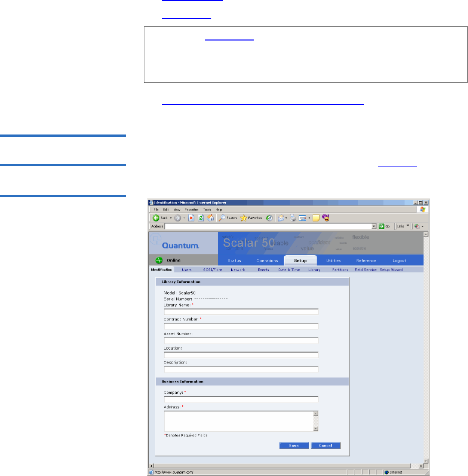
Chapter 3 Quantum Scalar 50 Remote Management
Setup
Quantum Scalar 50 User’s Guide 85
•Setup Wizard
•Secure Key
•Secure Key Best Practices and Tape Migration
Accessing the Setup
Page 3To access the Setup page, click Setup from the contents frame.
The management frame displays the Setup page (see figure 58).
Figure 58 Setup Page
Note: The Secure Key tab is only available under the Setup page
when the secure key administrator (skadmin) is logged onto
the system AND a secure key capable tape drive (DLT-S4) is
installed in the library.

Chapter 3 Quantum Scalar 50 Remote Management
Setup
Quantum Scalar 50 User’s Guide 86
Identification 3The identification information is used to identify the library to assist
customer support when servicing the library.
1To access the Identification page, from the Setup page, click on the
Identification tab at the top of the page.
The Identification page displays (see figure 58).
2Edit the identification information as desired (see table 20 for a
description of the fields).
3Click Save when complete.
Table 20 Identification
Information Field Description
Model Display only. Not entered by user
Serial Number Display only. Not entered by user
Library Name* Enter a name to identify this specific library
Contract
Number*
Enter the contract number for the library. This is
used to identify the library to customer support.
Asset Number Customer internal tracking number.
Location Enter the location of the library. This helps to
identify the library when remotely controlling
multiple machines.
Description Enter a short description of the library.
Company* Enter the company name where the library is
located
Address* Enter the company address where the library is
located
*Indicates a required field.
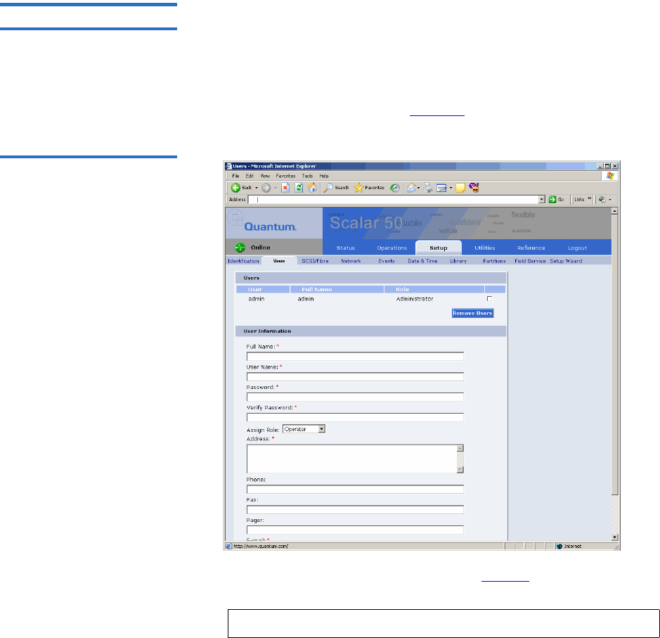
Chapter 3 Quantum Scalar 50 Remote Management
Setup
Quantum Scalar 50 User’s Guide 87
Users 3This section allows users to be added to the library configuration. The
user access is also controlled from this section as well as email
notification.
1To access the Users page, from the Setup page, click on the Users tab
at the top of the page.
The Users page displays (see figure 59).
Figure 59 Users Page
2Edit the user information as desired (see table 21 for a description of
the fields).
3Click Apply when complete.
4To remove a user, select the user check box and click Remove User.
Note: The username and password are limited to 7 characters.

Chapter 3 Quantum Scalar 50 Remote Management
Setup
Quantum Scalar 50 User’s Guide 88
Table 21 User Information
Key Users 3The Key User is the only user that has the ability to create, modify, and
delete a Secure Key for the library. The Key User also has the ability to
enable and disable Secure Capable Drives for reading and writing data to
and from tapes using the Secure Keys.
Creating a Key User 3
When a user is created with administrator privileges (other than the
default admin user), the Create Key User section appears at the bottom of
the Users page (see figure 60).
Field Description
Full Name* Enter the full name of the user
User Name* Enter a user name. The user name can be no
more than seven characters.
Password/Verify
Password*
Enter a password. The password can be no more
than seven characters.
Assign Role Select either Administrator or Operator for user
privileges. An operator only has access to
library status information. An administrator has
access to all areas of the remote management
pages.
Address* Enter an address for the user’s location
Phone Enter the users phone number
Fax Enter the users fax number
Pager Enter the users pager number
E-mail* Enter the users email address
Add to Events E-
mail List
Adds this user to the email events list.
*Indicates a required field.
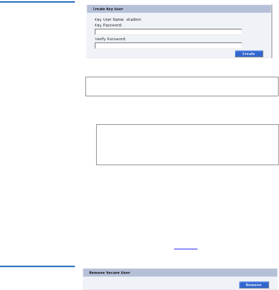
Chapter 3 Quantum Scalar 50 Remote Management
Setup
Quantum Scalar 50 User’s Guide 89
Figure 60 Create Key User
To create a Key User:
There is only one Key User and the username is always skadmin.
1Enter a secure password.
2Verify the secure password by entering the password a second time
in the Verify Password box.
3Click Create to create the Key User.
The Key User is created.
Remove Key User 3
Once the Key User is added, the Remove Secure User section displays at
the bottom of the Users page (see figure 61).
Figure 61 Remove Secure
User
To remove the Key User, click Remove.
Note: Only users with administrator privileges (other than the
default administrator) can create a secure user.
Note: Key User Passwords must be at least four characters long
and include at least one non-alphanumeric character.
Spaces, double quotes (“), and blank passwords are
rejected. Key User Password and Verify Password must
match.
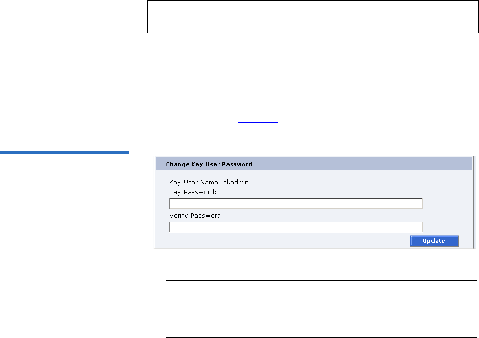
Chapter 3 Quantum Scalar 50 Remote Management
Setup
Quantum Scalar 50 User’s Guide 90
The Key User is removed.
Updating the Key User Password 3
To update the secure key password:
1Log on to the library as the Key User (username: skadmin).
2Enter the current Key User Password.
3Click the Users tab.
The Change Key User Password section displays at the bottom of the
Users page (see figure 62).
Figure 62 Change Key User
Password
4Enter a new Key User Password.
5Verify the Key User Password by entering the password a second
time in the Verify Password box.
6Click Update to update the Key User Password.
The Key User Password is updated.
Note: Only the Key User (logged in as skadmin) can change the key
user password.
Note: Key User Passwords must be alphanumeric strings of at
least one character. A blank secure password will be
rejected. Key User Password and Verify Password must
match.
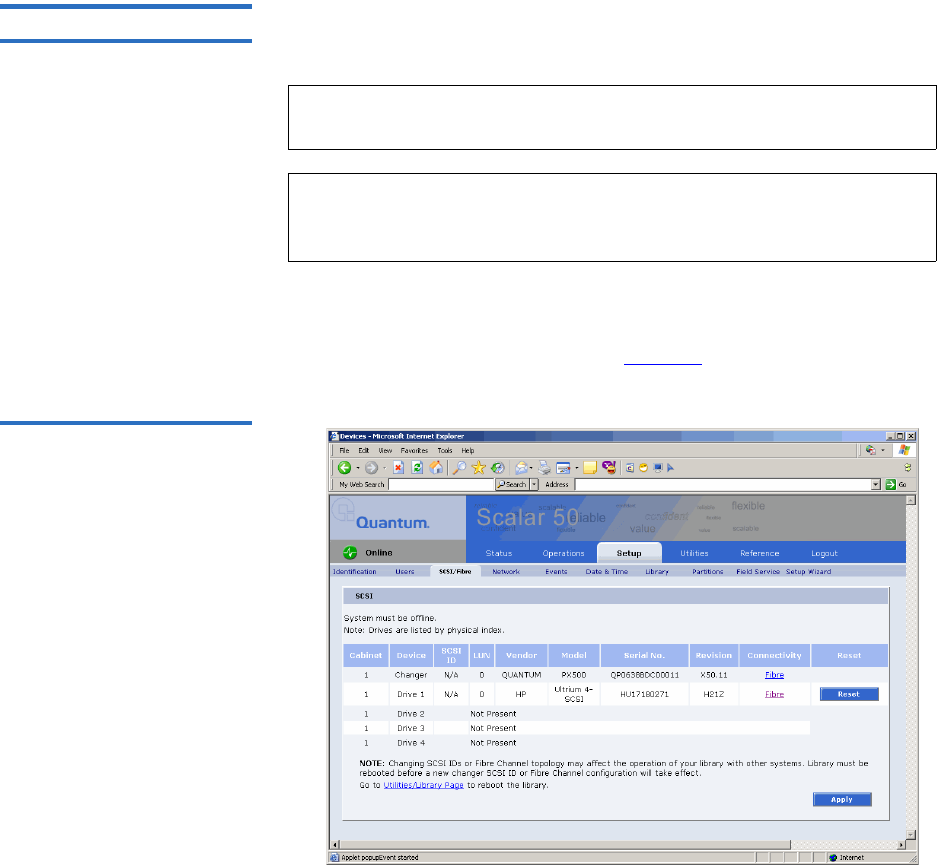
Chapter 3 Quantum Scalar 50 Remote Management
Setup
Quantum Scalar 50 User’s Guide 91
SCSI/Fibre 3This section allows the user to set the SCSI IDs for the changer (library)
and every tape drive within the library and also configure any Fibre
Channel tape drives.
1To access the SCSI/Fibre page, from the Setup page, click on the SCSI/
Fibre tab at the top of the page.
The SCSI/Fibre page displays (see figure 63).
Figure 63 SCSI Page
2To change a SCSI ID, enter the ID number in the field next to the
device and click Apply.
Note: You can also determine the tape drive firmware revision from
the SCSI/Fibre page.
Note: SAS tape drives do not require a SCSI ID and cannot be
configured. Use the default tape drive configuration
information.

Chapter 3 Quantum Scalar 50 Remote Management
Setup
Quantum Scalar 50 User’s Guide 92
To change a drive SCSI ID, the cabinet must be off-line.
3Click the device (tape drives) to view the drive details.
Native Fibre Channel Tape Drives 3
To configure the Native Fibre channel topology, speed, and loop ID:
1Click on the Fibre link under the Connectivity type.
The media changer or tape drive configuration screen displays. Refer
to table 22 for configuration options.
Table 22 Native Fibre Channel
Configuration Options
iSCSI Bridge 3This section allows users manage the TC2201 iSCSI bridges installed in
the cabinet.
Note: Changing SCSI IDs or Fibre Channel topology may affect
the operation of your library with other systems. Library
must be rebooted before a new changer SCSI ID or Fibre
Channel configuration will take effect.
Configuration Option Description
Configured Speed Select 1 G, 2 G, 4G, or Auto
Negotiate to set the configured
speed
Configured Topology Select point-to-point, arbitrated
loop, or Auto negotiate to set the
configured topology.
Loop ID Select the loop ID. The loop ID
can only be set when the
configured topology is set to
arbitrated loop.
Note: The iSCSI bridge information only displays when a iSCSI
bridge is installed in the library.
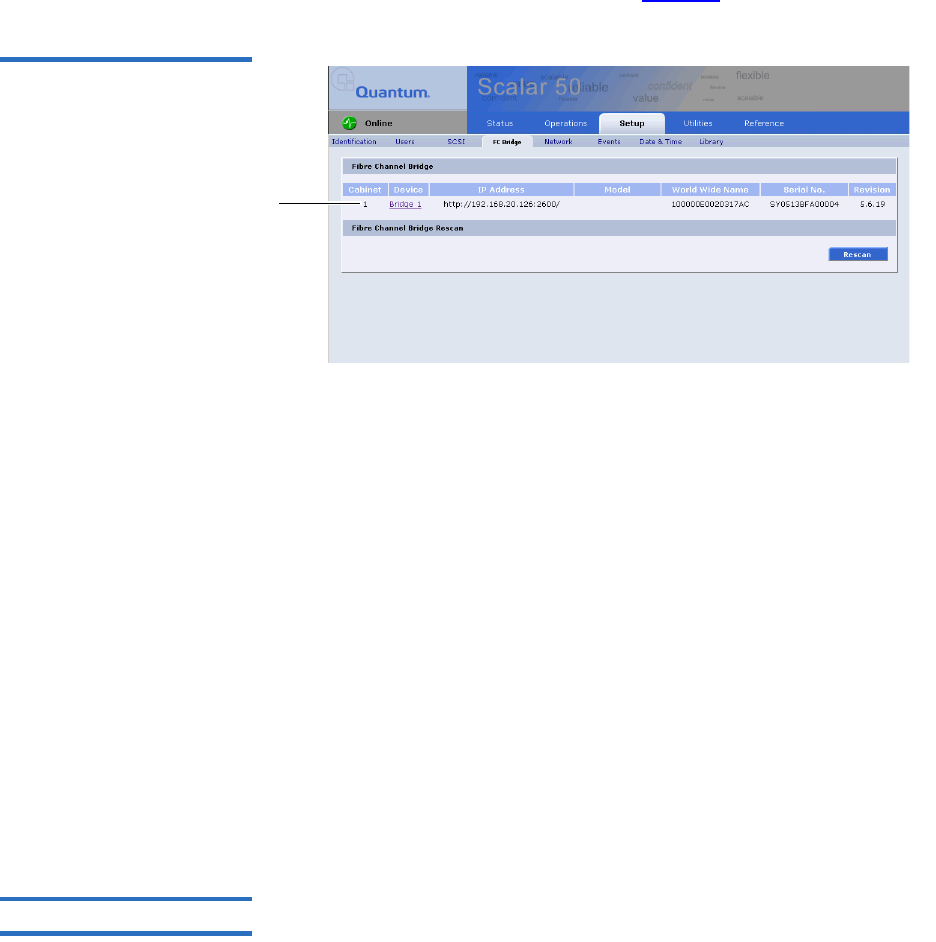
Chapter 3 Quantum Scalar 50 Remote Management
Setup
Quantum Scalar 50 User’s Guide 93
1To access the iSCSI Bridge page, from the Setup page, click on the
iSCSI Bridge tab at the top of the page.
The iSCSI Bridge page displays (see figure 64).
Figure 64 iSCSI Page
Bridge links
The iSCSI bridge page displays:
• Cabinet number(s)
• Device number(s)
• IP address for the iSCSI bridge
• Model of the iSCSI bridge
• World wide name for the iSCSI bridge
• Serial number for the iSCSI bridge
• Current firmware revision on the iSCSI bridge
2Click Rescan to discover new iSCSI bridges or updated firmware.
3Click on the iSCSI bridge you want to manage.
The TC2201 web interface displays. For more information on the
TC2201 iSCSI bridge and the web interface, see the Quantum TC2201
User’s Guide (PN 81-81539) included on the Quantum Scalar 50
documentation CD.
Network 3The network information section allows the user to enter network
information so the library can be controlled remotely via an Ethernet
network.
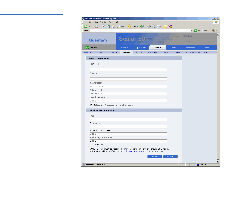
Chapter 3 Quantum Scalar 50 Remote Management
Setup
Quantum Scalar 50 User’s Guide 94
1To access the Network page, from the Setup page, click on the Network
tab at the top of the page.
The Network page displays (see figure 65).
Figure 65 Network Page
2Edit the network information as desired (see table 23 for a description
of the fields).
3Click Save.
The Quantum Scalar 50 will not use the new network information
until it has been rebooted (see “Setup” on page 84).

Chapter 3 Quantum Scalar 50 Remote Management
Setup
Quantum Scalar 50 User’s Guide 95
Table 23 Network
Configuration Fields
Events 3The Events page allows the user to designate what library events are
emailed to users as well as setup SNMP traps.
1To access the Events page, from the Setup page, click on the Events
tab at the top of the page.
The Events page displays (see figure 66).
Field Description
Hostname* View or set the hostname for the library (for
example, the DNS name)
Domain* View or set the domain name for the library
IP Address* View or set the IP address for the library
Subnet Mask* View or set the subnet mask for the library
Default Gateway* View or set the default gateway for the library
Obtain IP from
DHCP Server
If your network uses a DHCP server to assign
device IP addresses dynamically, select this box
Email Server View or set the email server information
Primary DNS
Address
View or set the primary DNS address
Secondary DNS
Address
View or set the secondary DNS address
*Indicates a required field.
Note: For a complete list of available library events, see chapter 4 on
page 137.
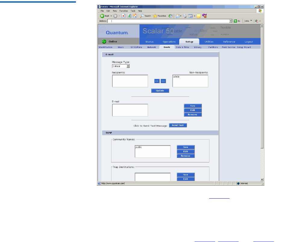
Chapter 3 Quantum Scalar 50 Remote Management
Setup
Quantum Scalar 50 User’s Guide 96
Figure 66 Events Page
2Edit the Email information as desired (see table 24 for a description of
the fields) and click Update.
3After editing the Email information, click the Send button to test the
notification system. If the test is not successful, verify the email server
information and the administrative recipients list and try again.
The Email area details are shown in table 24, table 25, and table 25.

Chapter 3 Quantum Scalar 50 Remote Management
Setup
Quantum Scalar 50 User’s Guide 97
Table 24 Email Notification
Table 25 Send Email Test
Field Description
Message Type:
Critical
When a hardware failure occurs on the Quantum
Scalar 50 system such as a transition to a
degraded, limited access, or failed system state,
an email is sent to everyone on the critical failure
recipient list.
Message Type:
Warning
When a warning state exists on the Quantum
Scalar 50 system such as an overtemp condition,
an email is sent to everyone on the warning
recipient list.
Message Type:
Informational
When an informational event has occurred on the
Quantum Scalar 50 system such as starting up or
shutting down the system, an email is sent to
everyone on the operator access recipient list.
New To add a new recipient to a specific list, type the
email address of the new recipient in the field
and click Save.
Edit To edit a recipient, select the individual email
address from the list and click Edit.
Remove To remove an email notification type from the E-
mail list, select the E-mail type and click Remove.
Field Description
Send Test To test the email notification system, click Send
Test. An email is sent to the critical e-mail
recipients list. If the test email is not successful,
verify the email server information and the
critical recipients list and try again.

Chapter 3 Quantum Scalar 50 Remote Management
Setup
Quantum Scalar 50 User’s Guide 98
SNMP 3
If the customer wishes to use the Quantum Scalar 50 system with a
network framework application such as HP OpenView, or CA Unicenter,
the SNMP configuration must be defined. SNMP stands for Simple
Network Management Protocol, a set of protocols for managing complex
networks. SNMP works by sending messages, called protocol data units
(PDUs), to different parts of a network. SNMP-compliant devices, called
agents, store data about themselves in Management Information Bases
(MIBs) and return this data to the SNMP requesters.
1Under Community Names (see figure 67), click New to enter the new
community information:
aA unique name in the Name field, the field holds up to 60
characters. No blank spaces are allowed.
bIP address in the IP Address field, if the value in the Network
Mask edit box ends in a zero, the value in the IP address edit box
must also end in a zero
cSubnet mask in the Network Mask field.
dAccess rights for the new community:
•Read Only allows SNMP read operations:
•Read/Write allows both SNMP read and write operations.
2Click Save.
A Results page displays indicating the community has been added.
3Click New in the Trap Destination area (see figure 67), to set the IP
addresses that are to receive the traps generated by the Quantum
Scalar 50, for example, 12.34.56.78.
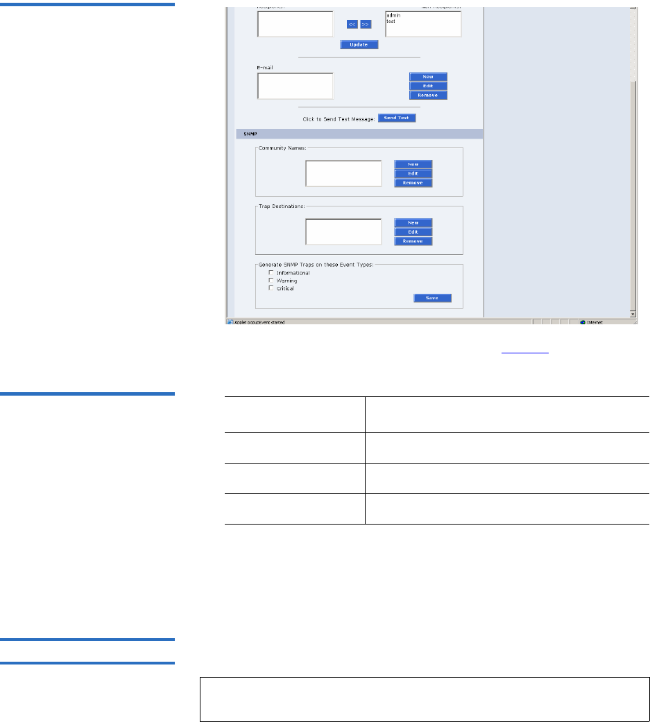
Chapter 3 Quantum Scalar 50 Remote Management
Setup
Quantum Scalar 50 User’s Guide 99
Figure 67 SNMP Section of
Event Page
4Enable the trap selections to be reported (see table 26):
Table 26 SNMP Trap
Selections
5Click Save.
A Results page displays indicating the configuration has been
changed.
Date & Time 3The date and time page allows the user to view and set the date and time
on the library. This allows the library to time stamp any events that occur.
Field Description
Informational If selected, Informational Traps are enabled.
Warning If selected, Warning Traps are enabled.
Critical If selected, Critical Traps are enabled.
Note: The Quantum Scalar 50 must be offline to adjust the time and
date.
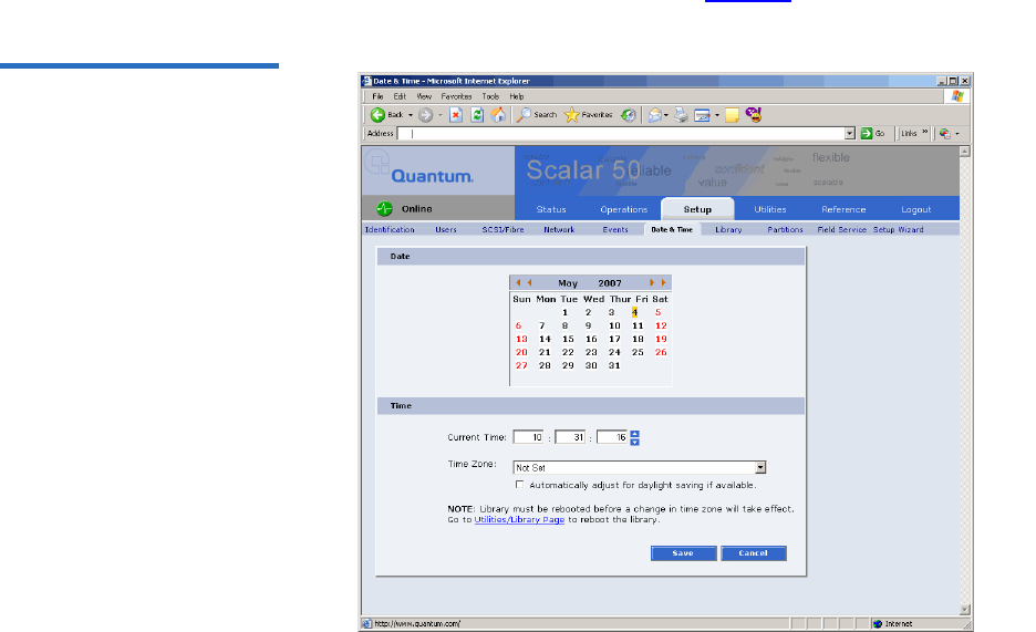
Chapter 3 Quantum Scalar 50 Remote Management
Setup
Quantum Scalar 50 User’s Guide 100
1To access the Date & Time page, from the Setup page, click on the Date
& Time tab at the top of the page.
The Date & Time page displays (see figure 68).
Figure 68 Date & Time Page
2Select Manual to manually set the system date and time using the
Change button for the system date and drop down boxes for the
system time.
3Click Save when complete.
The Quantum Scalar 50 will not use the new date and time zone
information until it has been rebooted.
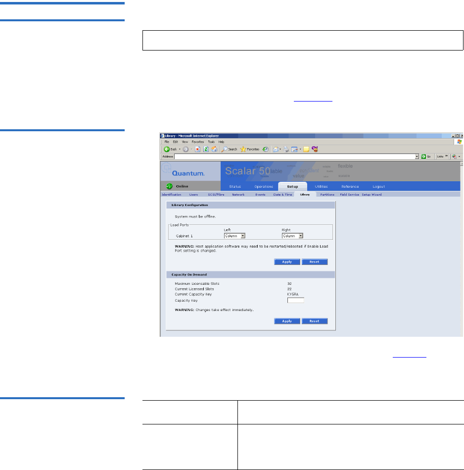
Chapter 3 Quantum Scalar 50 Remote Management
Setup
Quantum Scalar 50 User’s Guide 101
Library 3The library configuration section allows the user to configure automatic
library settings.
1To access the Library page, from the Setup page, click on the Library
tab at the top of the page.
The Library page displays (see figure 69).
Figure 69 Library Page
2Edit the Library Configuration settings as desired (see table 27 for a
description of the fields) and click Apply.
Table 27 Library Configuration
3Click Reset to return the library to its original settings.
Note: The library must be offline to change the library settings.
Field Description
Enable Left Load
Port/Right Load
Port
When enabled, the Left Load Port/Right Load
Port will act as load ports. When disabled, they
will be use as regular slots.

Chapter 3 Quantum Scalar 50 Remote Management
Setup
Quantum Scalar 50 User’s Guide 102
4Enter the Capacity Key (see table 28 for a description of the fields) and
click Apply.
Table 28 Capacity on Demand
Configuration
Caution: Changes to the number of licensed slots takes effect
immediatly.
5Click Reset to return the library to its original settings.
Partitions 3Library partitioning provides the capability to divide the library’s storage
elements into separate partitions, usable by separate host computers on
the same network. The maximum number of partitions per library is four
partitions; however, the number of partitions is limited by the number of
Note: Capacity on demand cannot be used in a partitioned
library.
Field Description
Maximum
Licensable Slots
Displays the maximum number of slots that can
be licensed in the library.
Current Licensed
Slots
Displays the current number of slots licensed in
the library.
• 22 SDLT/26 LTO slots = Level 1 or default
library capacity
• 32 SDLT/38 LTO slots = Level 2 or full library
capacity
Current Capacity
Key
Displays the current capacity key for the library.
Capacity Key To enable all of the available slots in the library
(Level 1 to Level 2 capacity), enter the new
capacity key for the library.
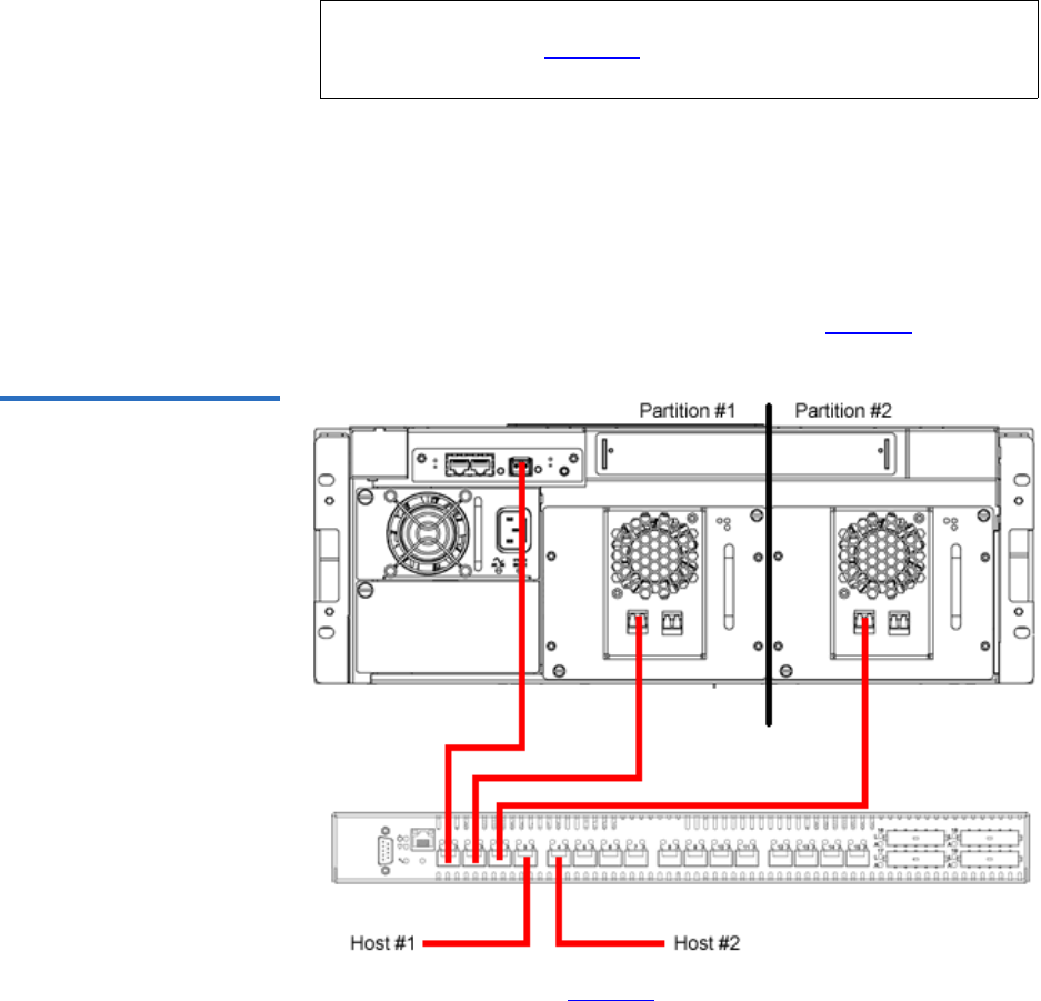
Chapter 3 Quantum Scalar 50 Remote Management
Setup
Quantum Scalar 50 User’s Guide 103
installed tape drives. For example: in a Scalar 50 with two tape drives
installed, only two partitions would be possible in this library.
Partitioning Requirements 3
Only a Scalar 50 library with a Native Fibre Channel interface can support
partitioning. You must also have a Fibre Channel switch available to
connect to the library Fibre Channel SCB, Fibre Channel hosts, and native
Fibre Channel tape drives. If you do not have a Fibre Channel switch
available, the library is limited to one partition (see figure 70).
Figure 70 Native Fibre
Channel Partition Example
In the example shown in figure 70, you must zone the Fibre Channel
switch as follows:
•Partition #1: Zone 1 must have the media changer (port 1), tape drive
1 (port 2) and host 1 (port 4).
Note: Partitioning cannot be used unless all libraries are at FULL
capacity. See “Library” on page 125 for more capacity key
information.

Chapter 3 Quantum Scalar 50 Remote Management
Setup
Quantum Scalar 50 User’s Guide 104
•Partition #2: Zone 2 must have the media changer (port 1), tape drive
2 (port 2) and host 2 (port 5).
Zoning the Fibre Channel switch as described above will allow the host to
view only the tape drive for it’s specific partition. The media changer is
visible to both partitions and hosts.
Scalar 50 Configurations that do NOT Support Partitioning 3
The following Scalar 50 configurations do NOT support partitioning:
•Scalar 50 Libraries Containing SAS Tape Drives - a library containing a
HP LTO-4 Half Height tape drive cannot be partitioned.
•Native Parallel SCSI interface - a parallel SCSI library cannot support
partitioning.
•iSCSI bridged Parallel SCSI - a parallel library with a TC2201 iSCSI
bridge cannot support partitioning.
•Native Fibre Channel without a switch - a Native Fibre Channel library
that does not have a Fibre Channel switch cannot support
partitioning.
•Scalar 50 with Level 1 Capacity - A default capacity library with only
four magazine columns available cannot be partitioned. You must
have FULL capacity to partition the library.
Accessing the Partitions Page 3
To access the Partitions page, click Partitions from the Setup page.
The management frame displays the Partitions page (see figure 71).
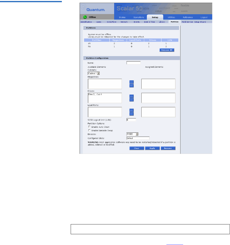
Chapter 3 Quantum Scalar 50 Remote Management
Setup
Quantum Scalar 50 User’s Guide 105
Figure 71 Partitions Page
The Partitions page contains a list of all user defined partitions and a
section for either creating a partition or changing a partition's
configuration and options.
Clicking on a partition name in the Partition list displays a detail
window listing all details for the selected partition.
Creating a Library Partition 3
To create a library partition:
1Enter the partition information listed in table 29 and click New to
create the partition.
Note: The library must be offline to create or edit a library partition.

Chapter 3 Quantum Scalar 50 Remote Management
Setup
Quantum Scalar 50 User’s Guide 106
Table 29 Creating a Partition Field Description
Partition Name Enter a unique name for the partition. Partition
names must start with a letter (a-z or A-Z), cannot
be longer than 10 characters, and cannot contain
spaces or special characters. Library, Global, and
Unassigned are reserved and cannot be used.
Cabinets Select an available cabinet.
Magazines Select one or more magazines from the
unassigned magazine list and move it to the
assigned magazine list. A partition MUST contain
at least one magazine.
Drives Select a drive or drives from the unassigned
drives list and move it to the assigned drive list. A
partition MUST contain at least one drive.
SCSI Logical
Unit (LUN)
Enter the SCSI logical unit number for this
partition. Each partition must have a unique LUN
designation. The default number is 0.
Load Port Select a load port from the load port list if
required for this partition. Load port elements can
be shared across multiple partitions.
Enable
Autoclean
Select this box to automatically clean the drives in
the partition when needed.
Emulate
P-Series
Select this box to return an P-Series inquiry string
to the host connected to this partition. The
partition will appear to the host as an P-Series
tape library.
Emulate Scalar
50
Select this box to return an Scalar 50 inquiry string
to the host connected to this partition. The
partition will appear to the host as an P-Series
tape library.
Enable Barcode
Swap
Enables/disables swapping media type prefix
from the back of barcode to the beginning.

Chapter 3 Quantum Scalar 50 Remote Management
Setup
Quantum Scalar 50 User’s Guide 107
Editing a Library Partition 3
To edit a library partition:
1Select the partition link under the Partitions section.
The area below the Partitions section displays the selected partition
settings.
2Edit the partition information as desired (refer to table 29) and click
Apply to save the changes.
3Click Clear to clear the partition settings and return to Creating a
Library Partition.
Configured
Slots
The configured slots option allows you to
designate the number of slots available and
reported to the host. If you are reducing the slot
count, the slots are reduced from the highest
element address first. The element addressing
begins with the left magazine, then the right
magazine, and finally the fixed slots. This means
that the first slots reduced are the fixed slots.
Note: The library must be offline to create or edit a library partition.
Field Description

Chapter 3 Quantum Scalar 50 Remote Management
Setup
Quantum Scalar 50 User’s Guide 108
Deleting a Library Partition 3
There are two ways to delete partitions:
1To delete a single library partition:
aSelect the partition link under the Partitions section.
bClick Remove to delete the partition.
The library partition is deleted.
2To delete all of the library partitions:
aClick Remove All.
All library partitions are deleted.
Field Service 3The Field Service page is limited to Quantum Field Service only.
Setup Wizard 3The Setup Wizard leads you through the process of setting up the most
common options for this library to be operational. Detailed customization
options, including settings modified by this wizard, can be changed via
the menus under the Setup tab.
1To access the Setup Wizard, from the Setup page, click on the Setup
Wizard tab at the top of the page.
The Setup Wizard displays (see figure 72).
Note: When a partition is added, edited, or deleted the library
must be rebooted for the changes to take effect.
Note: The library will need to reboot for changes to take effect. Host
application software may need to be restarted/rebooted as
well.

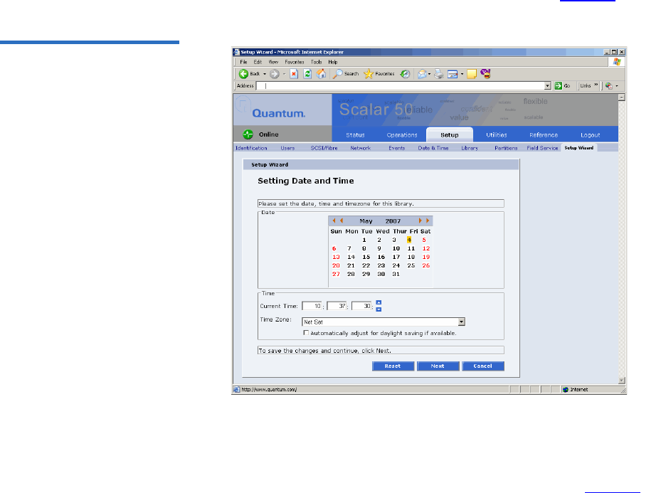
Chapter 3 Quantum Scalar 50 Remote Management
Setup
Quantum Scalar 50 User’s Guide 110
The Setup Wizard (Date and Time) page displays (see figure 74).
Figure 74 Setup Wizard (Date
and Time)
4Set the system date and time using the Change button for the system
date and drop down boxes for the system time.
5Click Next to continue.
The Setup Wizard (Configure Devices) page displays (see figure 75).
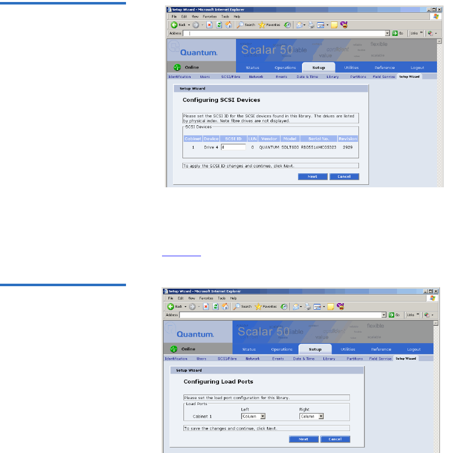
Chapter 3 Quantum Scalar 50 Remote Management
Setup
Quantum Scalar 50 User’s Guide 111
Figure 75 Setup Wizard
(Configure Devices)
6Set the SCSI ID for the SCSI devices in the library.
7Click Next to continue.
The Setup Wizard (Configuring Load Ports) page displays (see
figure 76).
Figure 76 Setup Wizard
(Configuring Load Ports)
8Enable or disable the load ports for this library.
9Click Next to continue.
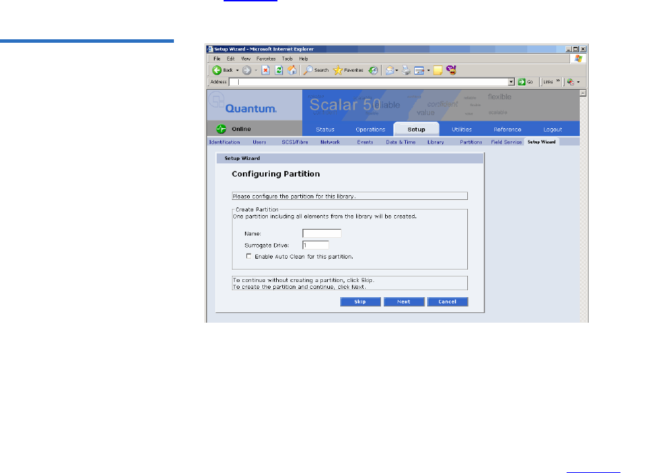
Chapter 3 Quantum Scalar 50 Remote Management
Setup
Quantum Scalar 50 User’s Guide 112
The Setup Wizard (Configuring Partitions) page displays (see
figure 77).
Figure 77 Setup Wizard
(Configuring Partition)
10 Create a partition for this library.
aEnter a name for the partition.
bSelect a LUN for the partition.
cEnable/disable Auto Clean for this partition.
11 Click Next to continue.
The Setup Wizard (Wizard Completed) page displays (see figure 78).
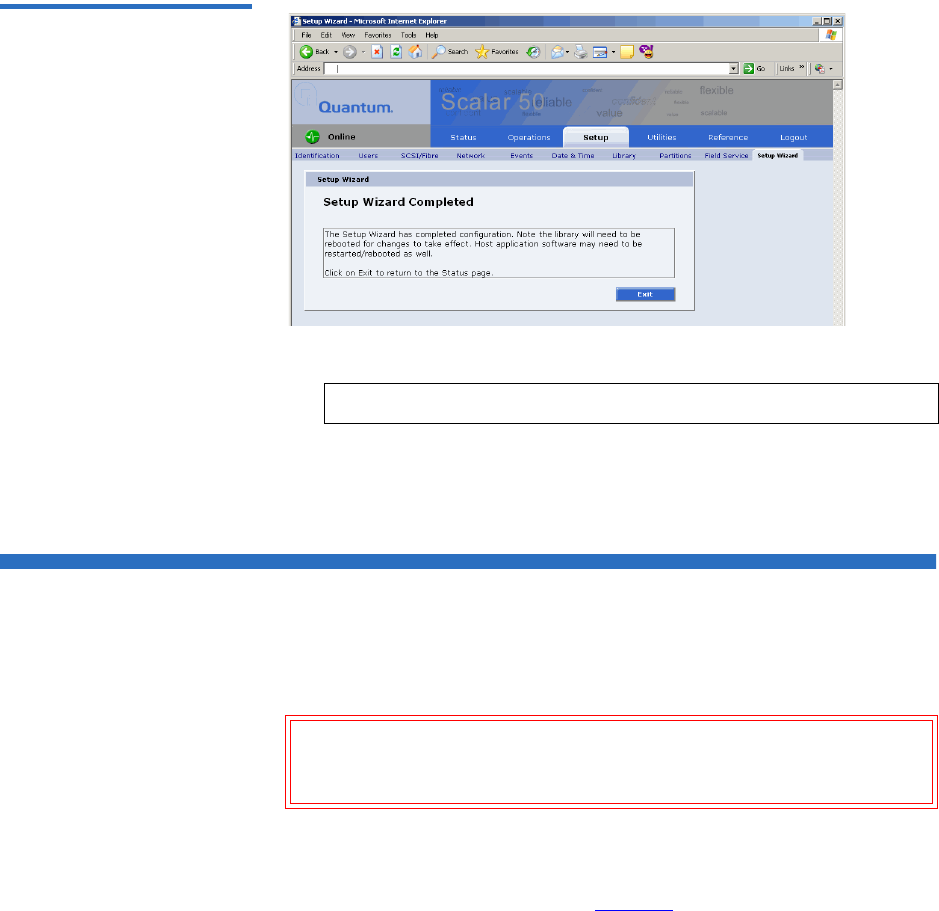
Chapter 3 Quantum Scalar 50 Remote Management
Secure Key
Quantum Scalar 50 User’s Guide 113
Figure 78 Setup Wizard
(Wizard Completed)
12 Click Exit to return to the Status page.
The Setup Wizard is complete.
Secure Key
The Secure Key tab displays when a secure user has been added to the
library and the secure user is logged in.
Caution: If the secure key information is lost, any tape cartridges
that were secured with the lost key will be unavailable for
reading or writing.
To access the Secure Key page, from the Setup page, click on the Secure
Key tab at the top of the page.
The Secure Key page displays (see figure 79).
Note: You must reboot the library for the changes to take effect.
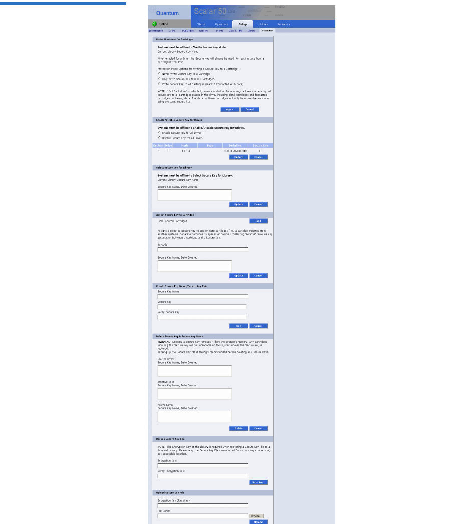
Chapter 3 Quantum Scalar 50 Remote Management
Secure Key
Quantum Scalar 50 User’s Guide 114
Figure 79 Secure Key Page
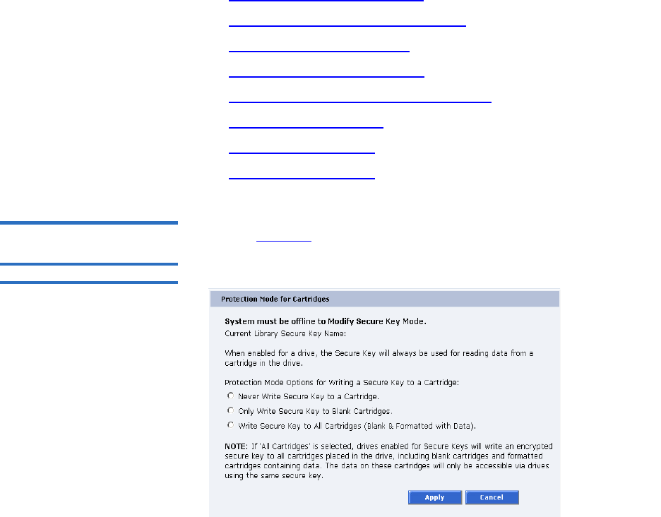
Chapter 3 Quantum Scalar 50 Remote Management
Secure Key
Quantum Scalar 50 User’s Guide 115
The Secure Key page is divided into the following sections:
•Protection Mode for Cartridges
•Enable/Disable Secure Key for Drives
•Select Secure Key for Library
•Assign Secure Key to Cartridge
•Create Secure Key Name/Secure Key Pair
•Delete Secure Key Name
•Backup Secure Key File
•Upload Secure Key File
Protection Mode for
Cartridges 3Refer to figure 80 for information on Protection Mode for Cartridges.
Figure 80 Protection Mode for
Cartridges
The Protection Mode for Cartridges area defines when the secure key is
used for a cartridge in a tape drive with a secure key enabled. In all
modes, the secure key is used to read data from cartridges that have a
pre-existing secure key. If the secure key on the cartridge does not match
the current secure key on the library, the data on the cartridge can not be
read.
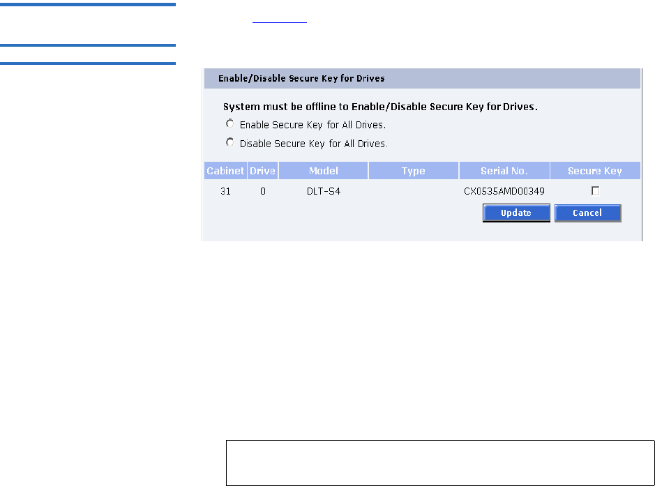
Chapter 3 Quantum Scalar 50 Remote Management
Secure Key
Quantum Scalar 50 User’s Guide 116
Three write protection modes are available:
•Never Write Secure Key to a Cartridge - The secure key will never
be written to a cartridge placed in a secured tape drive.
•Only Write Secure Key to Blank Cartridges - The secure key will
only be written to blank, unformatted cartridges.
•Write Secure Key to All Cartridges - The secure key will be written
to all cartridges, including blank and formatted cartridges
containing data. This mode may be used to apply a secure key to
cartridges with pre-existing data.
Enable/Disable Secure
Key for Drives 3Refer to figure 81 for information on Enable/Disable Secure Key for Drives.
Figure 81 Enable/Disable
Secure Key for Drives
The secure key can only be used with tape drives that are secure key
capable. This section lists the tape drives in the library that are secure key
capable. A checkmark in the Secure Key column indicates a secure key is
enabled for the tape drive.
1The secure key can be enabled or disabled for all tape drives by
clicking the corresponding radio button.
2Click the Secure Key check box for individual tape drives to enable/
disable secure key for a tape drive.
3Click Update to activate the changes.
Note: The system must be offline to Enable/Disable Secure Key
setting for drives.
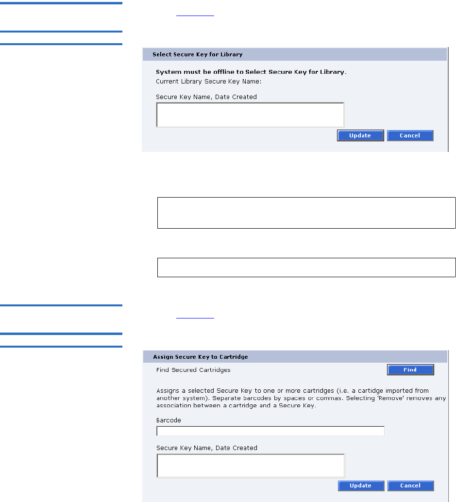
Chapter 3 Quantum Scalar 50 Remote Management
Secure Key
Quantum Scalar 50 User’s Guide 117
Select Secure Key for
Library 3Refer to figure 82 for information on Select Secure Key for Library.
Figure 82 Select Secure Key
for Library
To select the secure key used by the library:
1Select the secure key name from the list of available names.
2Click Update.
Assign Secure Key to
Cartridge 3Refer to figure 83 for information on Assign Secure Key to Cartridge.
Figure 83 Assign Secure Key
to Cartridge
Note: Selecting None to will cause the library to NOT use a
secure key.
Note: The system must be offline to modify a secure key.
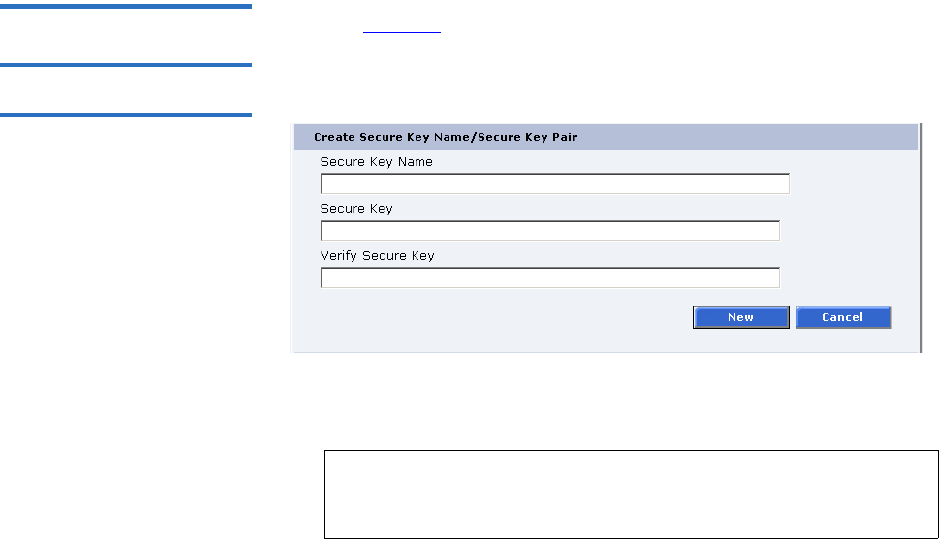
Chapter 3 Quantum Scalar 50 Remote Management
Secure Key
Quantum Scalar 50 User’s Guide 118
Click Find to list all secured cartridges and their assigned secure key
names.
To assign a secure key to a cartridge:
1Enter the barcode of the cartridge. Separate multiple barcodes with
either spaces or commas.
2Select a secure key name from the list of available names.
3Selecting Remove will remove the association between the cartridge
and a secure key name in the cartridge database.
4Click Update to accept the changes.
Create Secure Key Name/
Secure Key Pair 3Refer to figure 84 for information on Create Secure Key Name/Secure Key
Pair.
Figure 84 Create Secure Key
Name/Secure Key Pair
To create a secure key name/secure key pair:
1Enter the Secure Key Name.
2Enter a securekey in the protected Secure Key field.
Note: The secure key name must be less than 12 characters, may
include spaces, but cannot contain the following
characters: ( ) = ;
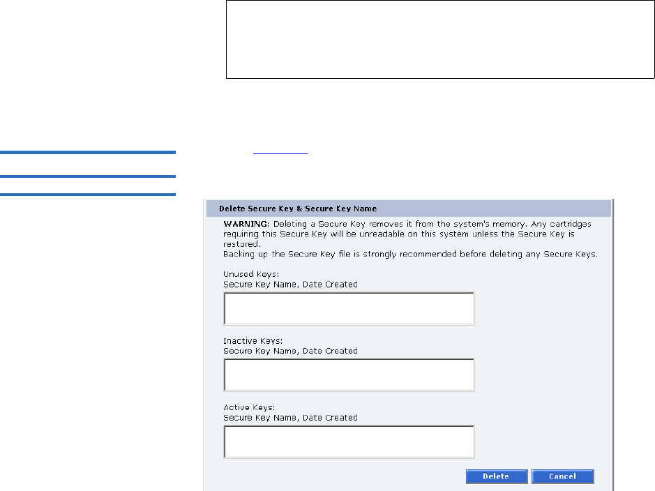
Chapter 3 Quantum Scalar 50 Remote Management
Secure Key
Quantum Scalar 50 User’s Guide 119
3Enter the same secure key in the Verify Secure Key field.
4Click New to create the secure key name/key pair.
Delete Secure Key Name3Refer to figure 85 for information on Delete Secure Key Name.
Figure 85 Delete Secure Key
Name
The Secure Key Names maintained on the library are displayed in one of
three lists:
•Unused Secure Keys - keys not associated with any cartridges or tape
drives currently in the system.
•Inactive Secure Keys - keys associated with cartridges in the library,
or currently assigned to the library, but not assigned to any tape
drives.
•Active Secure Keys - keys currently assigned to a tape drive.
To delete a Secure Key Name/Secure Key pair from the library:
Note: The Secure Key must be at least 8 characters and no more
than 32 characters. The Secure Key must also contain at
least one non-alphanumeric character and cannot include
spaces or double quotes (““).
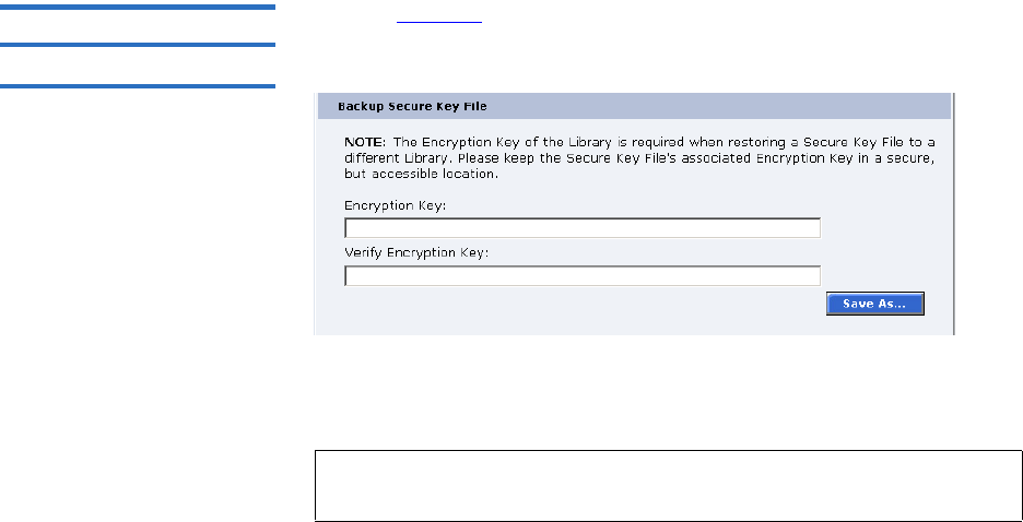
Chapter 3 Quantum Scalar 50 Remote Management
Secure Key
Quantum Scalar 50 User’s Guide 120
1Select the desired Secure Key Names from the available lists.
2Click Delete.
A confirmation message will be displayed, click Yes to continue.
Any tape drives that have been secure key enabled will remain
enabled, but the secure key will not be used to read or write
cartridges.
Backup Secure Key File 3Refer to figure 86 for information on Backup Secure Key File.
Figure 86 Backup Secure Key
File
The list of Secure Key Name/Secure Key Pairs maintained on the library
should be backed up to a local device whenever a change is made to the
security keys.
1Click Save As...
The browser displays a download link.
2Right-click on the download link and select Save As... to select a path
and name the file.
3Click OK.
Note: Note the library's Encryption Key. The Encryption Key is
required when restoring the file to any library.
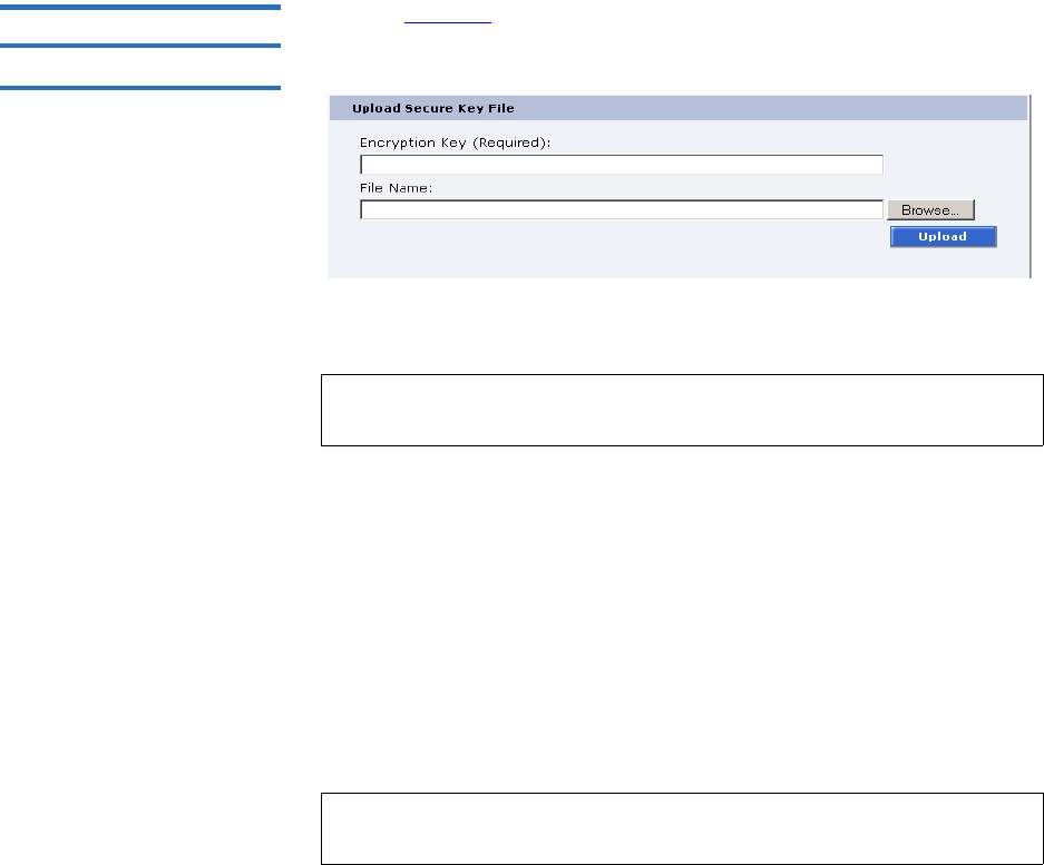
Chapter 3 Quantum Scalar 50 Remote Management
Secure Key
Quantum Scalar 50 User’s Guide 121
Upload Secure Key File 3Refer to figure 87 for information on Upload Secure Key File.
Figure 87 Upload Secure Key
File
A file containing a list of Secure Key Name/Secure Key Pairs can be
restored to the library.
To upload (restore) a Secure Key File:
1Enter the encryption key of the original library.
2Enter the path and file name of the file to be uploaded (click
Browse...)
3Click Upload button.
A progress window is displayed indicating when the upload is
complete or if any errors occurred during the upload or restoration of
the file.
The Secure Key page is refreshed listing restored secure keys.
Note: The user defined encryption key of the library originally
maintaining the list is required to restore the file.
Note: An error is displayed if the encryption key provided does not
match the encryption key used to encode the secure keys.

Chapter 3 Quantum Scalar 50 Remote Management
Secure Key Best Practices and Tape Migration
Quantum Scalar 50 User’s Guide 122
Secure Key Best Practices and Tape Migration
This section provides information on “Best Practices” when
implementing DLTSage Tape Security and also instructions for migrating
your security keys from one library to another.
For more information on implementing DLTSage Tape Security with
your specific library, refer to the following Quick Start Guides provided
on the documentation CD included in the library accessory kit:
•Scalar 50 DLTSage Tape Security Quick Start Guide PN 81-81627
•PX720 DLTSage Tape Security Quick Start Guide PN 81-81588
Best Practices 3When implementing DLTSage Tape Security in your tape library, there
are several “Best Practices” or guidelines to consider:
• The encryption key file should be saved off of the library at least once
a month or whenever a large amount of tapes is removed/added to
the library. It is a good idea to use the date in the file name of the
backup file.
• In the library remote management pages, the secure key and tape
cartridge barcode associations are displayed when you click Find in
the Assign Secure Key to Cartridge section without a specific barcode
entered in the barcode edit box. You should save this file off of the
library so the secure key and barcode associations are available in
case of disaster recovery or when moving the tapes from one library
to another. This also makes it easy to copy and paste the barcode
numbers into the PX720 and Scalar 50 remote management pages
when associating barcodes with secure keys.
• Secure key and encryption password information should NOT be
stored in unsecured areas.
Key Migration Scenarios3The following examples describe two key migration scenarios:
•Disaster Recovery Scenario
•Tape Cartridge Migration Scenario
Chapter 3 Quantum Scalar 50 Remote Management
Secure Key Best Practices and Tape Migration
Quantum Scalar 50 User’s Guide 123
Disaster Recovery Scenario 3
In the disaster recovery scenario, the original library is inoperable, but
secure keys and barcode associations have been saved off of the system
and are available on the network.
1Remove the tape cartridges and place them in another tape security
enabled library.
2Follow the steps listed below (beginning with step 2) to import
cartridges and associate barcodes with secure keys.
Tape Cartridge Migration Scenario 3
In this tape cartridge migration example, tape cartridges have been
secured in one tape library (PX720 or Scalar 50) and you want to move
them into another PX720 or Scalar 50 library and access them:
1On the original library containing the cartridges:
aAccess the library remote management screens.
bIn the Backup Secure Key file section, backup the secure key file.
This encrypted file contains all of the secure keys and bar code
associations in the original library. Once you click Save as... you
must right-click on the download link to save the file local
directory. This file must be located on a network resource that is
available to the new library.
cExport the tape cartridges from the library.
2On the new library:
aImport the tape cartridges into the new library.
bUpload the secure key file from the original library:
• If you are uploading a backup file from a PX720 to a Scalar 50
library, you must enter the serial number of the original
PX720 in the Encryption Key field, browse to the backup file,
and click Upload.
• If you are uploading a file from a Scalar 50 library to a PX720,
you must enter the user defined key name in the Serial
number field, browse to the backup file, and click Upload.
cWhen the file is uploaded, the secure keys from the original
library display in the secure key name list.
The tape cartridges are now available for reading and writing.
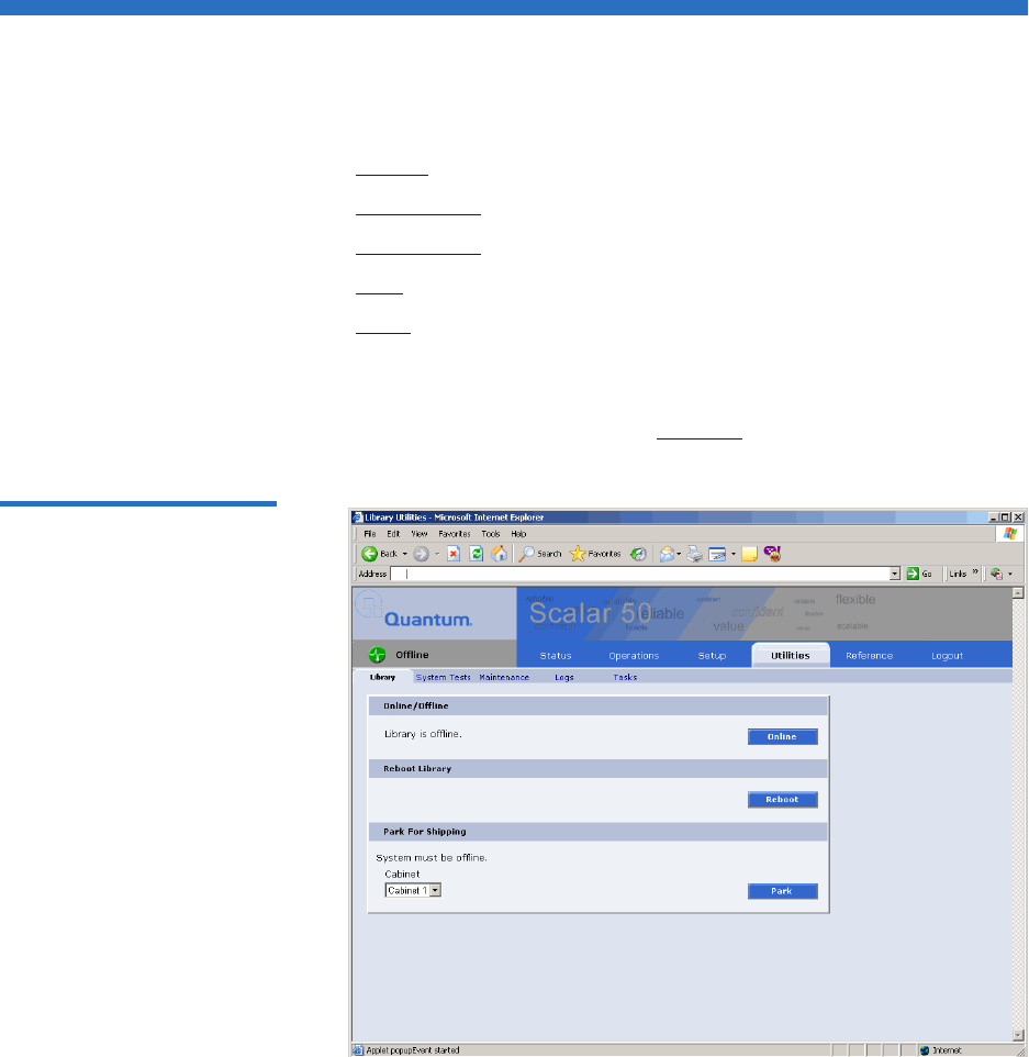
Chapter 3 Quantum Scalar 50 Remote Management
Utilities
Quantum Scalar 50 User’s Guide 124
Utilities
The Utilities page is divided into the following sections:
•Library
•System Tests
•Maintenance
•Logs
•Tasks
1To access the Utilities page, from the Overview page, click on the
Utilities tab at the top of the page.
The Utilities page displays (see figure 88):
Figure 88 Utilities Page
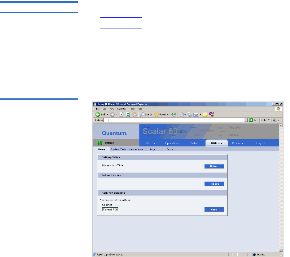
Chapter 3 Quantum Scalar 50 Remote Management
Utilities
Quantum Scalar 50 User’s Guide 125
Library 3The library page is divided into the following sections:
•Online/Offline
•Reboot Library
•Park for Shipping
•Bridge Rescan
To access the Library page, from the Utilities page, click on the Library tab
at the top of the page.
The Library page displays (see figure 89):
Figure 89 Library Page

Chapter 3 Quantum Scalar 50 Remote Management
Utilities
Quantum Scalar 50 User’s Guide 126
Online/Offline 3
The online/offline button allows the user to turn the cabinet online or
offline remotely. The action displayed on the button will depend on the
current state of the library or cabinet. If the library (cabinet) is online,
Offline button will be displayed. If the library (cabinet) is in the offline
state, an Online button will be displayed.
To change the library online/offline:
1Click the button to change the library state to online or offline.
The library changes state to online or offline.
Reboot Library 3
The Reboot Library button allows you to remotely reboot the library.
To reboot the library:
1Click Reboot.
The library reboots.
Park for Shipping 3
The Park for Shipping button allows you to remotely park the robot for
library shipment. This places the library hand in the correct position for
shipment and powers down the library, HOWEVER, you must place the
library hand restraint on the library hand prior to shipping the library.
Refer to appendix D on page 216 for more information on shipping the
library.
Caution: Shipping the library without installing the library hand
restraint may result in damaging the hand.
To park the library hand:
1Select the cabinet and click the Park button.
The library hand moves to the shipment position.
Note: You must remove all tape cartridges from the library prior to
parking the library robotics for shipment.
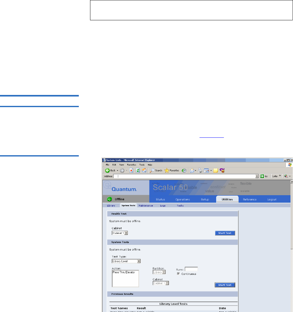
Chapter 3 Quantum Scalar 50 Remote Management
Utilities
Quantum Scalar 50 User’s Guide 127
Bridge Rescan 3
The bridge rescan button re-discovers any iSCSI bridges installed in the
cabinet. Details of the scan will be presented under Bridges tab.
To rescan iSCSI bridges installed in the cabinet:
1Click Rescan.
The iSCSI bridges are scanned.
System Tests 3The system tests section allows the user to run a series of tests on an
individual cabinet axis.
1To access the System Test page, from the Utilities page, click on the
System Test tab at the top of the page.
The System Test page displays (see figure 90).
Figure 90 Selftest Page
Note: The Bridge Rescan button only displays if a TC2201 iSCSI
bridge is installed in the library.

Chapter 3 Quantum Scalar 50 Remote Management
Utilities
Quantum Scalar 50 User’s Guide 128
To run a Health Test on a cabinet:
1Click the Start Test button.
The system performs a health test on all robotic axis. Previous test
results can be viewed below.
System Tests 3
The system test section allows the user to run a series of tests on an
individual cabinet axis.
1To access the System Tests page, from the Utilities page, click on the
System Tests tab at the top of the page.
The System Tests page displays (see figure 91).
Figure 91 System Tests Page
Note: The library must be off-line before executing any health tests.
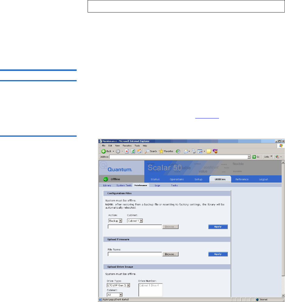
Chapter 3 Quantum Scalar 50 Remote Management
Utilities
Quantum Scalar 50 User’s Guide 129
To run a System Test on a cabinet:
1Select an action and a number of runs and click Apply.
The cabinet performs the system test. If you leave the runs field
empty, the system test will run continuously until you abort the
system test. Previous test results can be viewed below.
Maintenance 3The maintenance section allows the user to backup or restore system
configuration files as well as upload new cabinet and tape drive
firmware.
1To access the Maintenance page, from the Utilities page, click on the
Maintenance tab at the top of the page.
The Maintenance page displays (see figure 92).
Figure 92 Maintenance Page
Note: The library must be off-line before executing any system tests.

Chapter 3 Quantum Scalar 50 Remote Management
Utilities
Quantum Scalar 50 User’s Guide 130
Configuration Files 3
Configuration files contain all of the configurable information on the
library (see table 30 for file types). This configuration file should be saved
on a local host on the same network. If the library configuration file is
corrupted, this backup configuration file can be uploaded back to the
library without reconfiguring the entire library.
Table 30 Configuration File
Types
1 Select file type and click on Apply.
Upload Firmware 3
The upload firmware section allows the user to remotely upload new
firmware to the library.
To upload firmware:
1Enter a path and filename where the file exists, or click Browse.
2 Click Apply to upload the file.
Configuration File Type Description
Backup Select Backup to save all user, network,
and library configuration information.
Use this file to replace all configurable
options on the library.
Restore Select Restore to restore a configuration
file from your computer to the library.
Factory Select Factory to restore the library to its
default factory configuration settings.
Note: After restoring configuration files or factory default settings,
the library will automatically reboot.
Note: If you are uploading library firmware to stacked libraries, refer
to Appendix E on page 226 for special instructions.

Chapter 3 Quantum Scalar 50 Remote Management
Utilities
Quantum Scalar 50 User’s Guide 131
The firmware image uploads to the library and reboots the library.
Upload Drive Image 3
The upload drive image section allows the user to remotely upload new
tape drive firmware to a specific tape drive within the library.
To upload drive firmware:
1Select an individual tape drive and number or select an entire cabinet
to update the drive firmware for all tape drives within the library
cabinet.
2Enter a path and filename where the tape drive firmware exists, or
click Browse.
3 Click Apply to upload the file.
The firmware image uploads to the tape drive(s) and reboots the
library.
Logs 3The Logs page displays the drive logs for the individual tape drives
within the library and also a failure analysis file.
To access the Logs page, from the Utilities page, click on the Logs tab at
the top of the page.
The Logs page displays (see figure 93):
Note: The library must be offline to update the drive firmware.
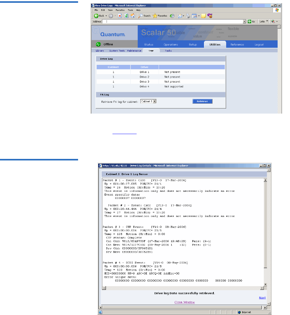
Chapter 3 Quantum Scalar 50 Remote Management
Utilities
Quantum Scalar 50 User’s Guide 132
Figure 93 Logs Page
Click the View Log link to view the log file for a specific tape drive
(see figure 94). The log sense information for the tape drive displays.
Click Next to see additional log sense information.
Figure 94 View Log Page
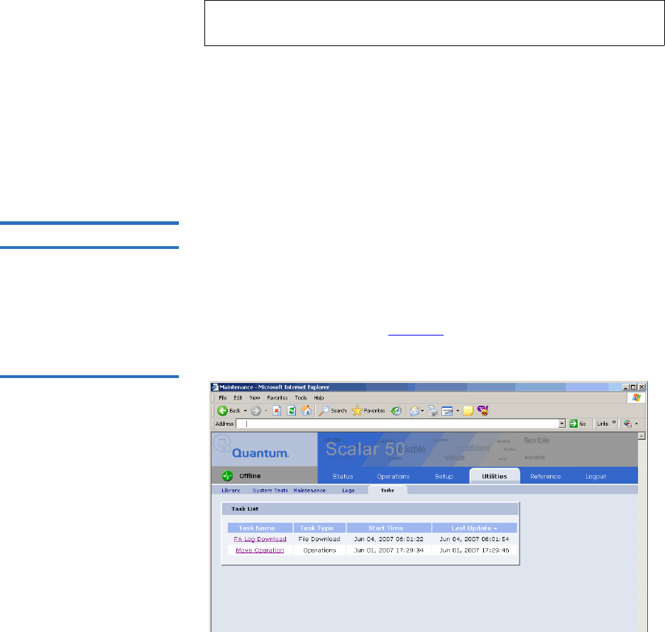
Chapter 3 Quantum Scalar 50 Remote Management
Utilities
Quantum Scalar 50 User’s Guide 133
FA Log File 3
The failure analysis log file (FA log) contains diagnostic information used
to troubleshoot problems with the library. This file can only used by
Quantum Customer Support. Have this file available prior to calling
Quantum Customer Support.
To retrieve a FA log file:
1Click Retrieve.
A window displays with the status of the FA log download process.
This will take several minutes. Once the command to retrieve the
library FA log has completed, click the Download FA Log link to save
the file to your local computer.
Tasks 3The Tasks page displays the last fifteen tasks that have been performed
on the library that required a status window. Clicking the task link
displays the task window whether it is still in progress or finished.
To access the Tasks page, from the Utilities page, click on the Tasks tab at
the top of the page.
The Tasks page displays (see figure 93):
Figure 95 Tasks Page
Note: It is recommended to turn the library offline prior to collecting
an FA log.
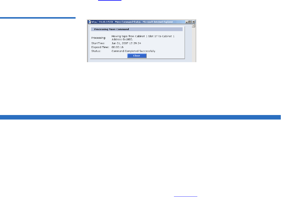
Chapter 3 Quantum Scalar 50 Remote Management
Reference
Quantum Scalar 50 User’s Guide 134
In the example above, a Move Operation task is displayed in the Task
Name list. Clicking the Move Operation link displays the following page
(see figure 96).
Figure 96 Task List Example
The page indicates that a move command has completed moving a tape
from cabinet 1 slot 17 to cabinet 1 address 0x1000, the start time and
elapsed time for the command to complete.
Reference
The links on this page provide access to various points of interest which
may be helpful in the operation and support of your library. Your
browser must have access to the internet for these links to work.
1To access the Reference page, click on the Links tab at the top of the
page.
The Links page displays (see figure 97).
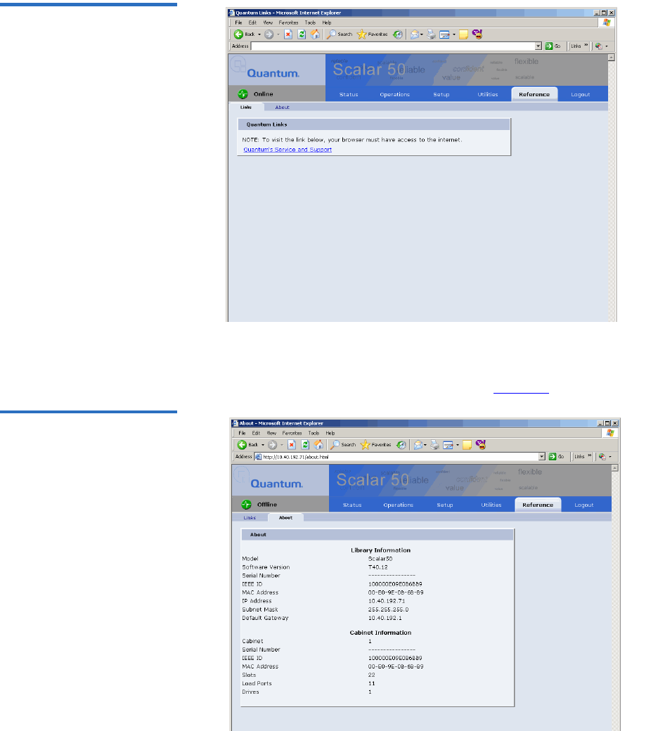
Chapter 3 Quantum Scalar 50 Remote Management
Reference
Quantum Scalar 50 User’s Guide 135
Figure 97 Reference Page
2To access the About page, click the About tab at the top of the page.
The About page displays the model number, software version, serial
number, and slot/drive configuration (see figure 98).
Figure 98 About Page

Chapter 3 Quantum Scalar 50 Remote Management
Logout
Quantum Scalar 50 User’s Guide 136
Logout
The Logout page allows you to logout of the Scalar 50 remote
management pages.
To logout of the library remote management pages, click Logout.
The session is closed. Start a new session by re-authenticating when
prompted or close your browser.

Quantum Scalar 50 User’s Guide 137
Chapter 4
4SNMP Trap List
This chapter provides the supported SNMP trap list for the Scalar 50 tape
libraries. The following table is sorted by the Reported By column:
1Code Update
2Diagnostic
3Drive Manager
4Event Manager
5Image Process
6OCP
7SCSI
8Servo
9System Manager
10 System Monitor
Event Details - indicates the text that appears on the OCP and also in the
Remote Management web pages.
Event Description - provides a more detailed description of the event that
occurred.
Category - indicates the type of SNMP trap (Informational, Warning, or
Critical)
Reported By - indicates the area of firmware that reported the event.

Chapter 4 SNMP Trap List
Quantum Scalar 50 User’s Guide 138
Event Detail Event Description Category Reported By
Start Backup System
Codeupdate (type/dest)
A backup flash update was
attempted.
Informational Code update
Start Sled Codeupdate
(type/dest)
A drive sled update was
attempted.
Informational Code update
Start Drive Codeupdate
(type/dest)
A drive update was attempted. Informational Code update
Loader Image size larger
than hdr entry (image
size)
The library failed the version
verification test.
Critical Code update
Loader Image size
smaller than hdr entry
(image size)
The library failed the version
verification test.
Critical Code update
Loader Image too large
for allocated memory
(image size)
The library failed the version
verification test.
Critical Code update
Invalid boot image The boot code used to initialize
the system is invalid. Update the
library firmware with the latest
version of code.
Critical Code update
Invalid drive image
(type/dest)
The tape drive software
downloaded into the library
memory is invalid.
Critical Code update
Invalid system image
(location)
The library software used for
system operation is invalid.
Update the library firmware with
the latest version of code.
Warning Code update
Start System
Codeupdate (type/dest)
A loader update was attempted. Informational Code update
Codeupdate successful
(type/dest)
A code update has completed. Informational Code update

Chapter 4 SNMP Trap List
Quantum Scalar 50 User’s Guide 139
Codeupdate failed
(status)
A code update has failed. Informational Code update
Backplane nv erase err
(region id/status)
Non Volatile memory on the back
plane could not be erased.
Replace the backplane to restore
normal library operations.
Critical Diagnostics
Backplane nv read err
(region id/status)
Non Volatile memory on the back
plane could not be read. Replace
the backplane to restore normal
library operations.
Critical Diagnostics
Backplane nv write err
(region id/status)
Non Volatile memory on the back
plane could not be written.
Replace the backplane to restore
normal library operations.
Critical Diagnostics
Hand-camera image fail The camera in the robotics hand
has failed to read an image.
Critical Diagnostics
Hand-camera init fail The camera in the robotics hand
has failed its initialization routine.
Critical Diagnostics
Selftest Camera FIFO
failure
The camera in the robotics hand
has failed to read its memory used
to transfer data.
Critical Diagnostics
Selftest display bram
failure
The diagnostic buffer used to
report test results is not large
enough to hold the data.
Critical Diagnostics
Scb-fpga camera fifo fail The memory on the system
controller board has failed to read
the memory used to transfer data.
Critical Diagnostics
Test details buffer
overflow (len/testId)
The diagnostic buffer used to
report test results is not large
enough to hold the data.
Critical Diagnostics
Test record semaphore
locked (index/tx-status)
An internal firmware error has
occurred.
Critical Diagnostics
Event Detail Event Description Category Reported By

Chapter 4 SNMP Trap List
Quantum Scalar 50 User’s Guide 140
Test structure corrupt
(testId)
An internal firmware error has
occurred.
Critical Diagnostics
Insufficient num cart for
test (num)
Not enough tape cartridges in the
library to complete the system
test.
Warning Diagnostics
Insufficient num drives
for test (num)
Not enough tape drives in the
library to complete the system
test.
Warning Diagnostics
Insufficient num empty
slots for test (num)
Not enough empty bins in the
library to complete the system
test.
Warning Diagnostics
Hand-cal offset fail The calibration test used to
compute offsets for the robotic
hand has failed.
Critical Diagnostics
Hand-theta cal offset fail The calibration test used to
compute offsets for the robotic
hand in rotation has failed.
Critical Diagnostics
Hand-trans cal offset fail The calibration test used to
compute offsets for the robotic
hand in translation has failed.
Critical Diagnostics
XY & hand cal offset fail The calibration test used to
compute offsets for the robotics
tray has failed.
Critical Diagnostics
XY & hand_theta cal
offset fail
The calibration used to compute
offsets for the robotics tray and
robotics hand has failed.
Critical Diagnostics
XY & hand_trans cal
offset fail
The calibration test used to
compute offsets for the robotics
tray and robotics rotation has
failed.
Critical Diagnostics
XY & Z cal offset fail The calibration test used to
compute offsets for the robotics
tray and the robotics up/down
motion has failed.
Critical Diagnostics
Event Detail Event Description Category Reported By

Chapter 4 SNMP Trap List
Quantum Scalar 50 User’s Guide 141
XY-cal offset fail The calibration test used to
compute offsets for the robotics
tray has failed.
Critical Diagnostics
Z & hand cal offset fail The calibration test used to
compute offsets for the robotics
tray up/down and robotics hand
has failed.
Critical Diagnostics
Z & hand_theta cal offset
fail
The calibration test used to
compute offsets for the robotics
tray up/down and robotics hand
rotation has failed.
Critical Diagnostics
Z & hand_trans cal offset
fail
The calibration test used to
compute offsets for the robotics
tray up/down and robotics hand
translation has failed.
Critical Diagnostics
Z-cal offset fail The calibration test used to
compute offsets for the robotics
tray up/down has failed
Critical Diagnostics
Hand-trans axis init fail The robotic hand could not
initialize the translation axis.
Critical Diagnostics
Hand-trans home fail The robotic hand could not home
the translation axis.
Critical Diagnostics
Hand-trans motor fail
(zone #)
The robotic hand has failed to
position translation to a
predetermined physical location.
Critical Diagnostics
Hand-theta axis fail
(zone #)
The robotic hand has failed to
position rotation to a
predetermined physical location.
Critical Diagnostics
Hand-theta axis init fail The robotic hand could not
initialize the rotation axis.
Critical Diagnostics
Hand-theta home fail The robotic hand could not home
the rotation axis.
Critical Diagnostics
Event Detail Event Description Category Reported By

Chapter 4 SNMP Trap List
Quantum Scalar 50 User’s Guide 142
Hand-theta motor fail
(zone #)
The robotic hand has failed to
position rotation to a
predetermined physical location.
Critical Diagnostics
Hand-theta neg position
fail (zone #)
The robotic hand has failed to
position rotation to a
predetermined physical location.
Critical Diagnostics
Hand-theta pos position
fail (zone #)
The robotic hand has failed to
position rotation to a
predetermined physical location.
Critical Diagnostics
Hand-theta position fail The robotic hand has failed to
position rotation to a
predetermined physical location.
Critical Diagnostics
API msg que send
shutdown err (tx-status)
An internal API could not send a
shutdown message.
Critical Diagnostics
API send response que
err (tx-status/fromId)
An internal API received a
command message error.
Critical Diagnostics
API send test msg que
err (tx-status/fromId)
An internal API received a
command message error.
Critical Diagnostics
Bad sender for get resp
que (taskId/sender)
An internal API received a
command message error.
Critical Diagnostics
Create main msg que err
(tx-status)
An internal API received a
command message error.
Critical Diagnostics
Create response msg que
err (tx-status)
An internal API received a
command message error.
Critical Diagnostics
Main msg que receive
err (tx-status)
An internal API received a
command message error.
Critical Diagnostics
Response msg que
receive err (tx-status)
An internal API received a
command message error.
Critical Diagnostics
Create test record
semaphore err (tx-status)
An internal API received a
command message error.
Critical Diagnostics
Event Detail Event Description Category Reported By

Chapter 4 SNMP Trap List
Quantum Scalar 50 User’s Guide 143
Ralu rnd number
generator reset
The random number generator
used to calculate the slot locations
for the internal Random Access
Load Unload (RALU) function
has been reset.
Informational Diagnostics
Elem move failed limits
check
A move to an element failed a
calibration limit.
Warning Diagnostics
Hand-communication
fail
The communications to the
robotic hand has failed.
Warning Diagnostics
XYZ-communication fail The communication to the robotic
hardware for moving the X,Y and
Z axis has failed.
Warning Diagnostics
Timeout waiting for
response (status/taskId)
A command sent by the
diagnostics module has timed out
waiting for a return from another
module in the system.
Critical Diagnostics
Z-axis init fail The Z (vertical) axis initialization
routine has failed.
Critical Diagnostics
Z-motor fail (zone #) The robotic hand has failed to
position the vertical axis to a
predetermined physical location.
Critical Diagnostics
Z-position fail (zone #) The robotic hand has failed to
position the vertical axis to a
predetermined physical location.
Critical Diagnostics
X-position fail (zone #) The robotic hand has failed to
position the XY axis to a
predetermined physical location.
Critical Diagnostics
XY-home fail The XY axis initialization routine
has failed to find its home
position.
Critical Diagnostics
XY-motor fail (zone #) The robotic hand has failed to
position the XY axis to a
predetermined physical location.
Critical Diagnostics
Event Detail Event Description Category Reported By

Chapter 4 SNMP Trap List
Quantum Scalar 50 User’s Guide 144
XY-position fail The robotic hand has failed to
position the XY axis to a
predetermined physical location.
Critical Diagnostics
XY-safe to rotate fail The safe to rotate sensor used to
home the XY axis could not be
seen by the calibration routine.
Warning Diagnostics
Y-position fail (zone #) The robotic hand has failed to
position the XY axis to a
predetermined physical location.
Critical Diagnostics
Bad SCSI Sense Data A command sent to the drive
received bad sense data.
Warning Drive
Manager
Aborted any open
exchanges
Drive communications has failed. Informational Drive
Manager
ADT login failed The library failed to login and set
up communication to a drive.
Critical Drive
Manager
Bad reply received The drive did not return a valid
response.
Warning Drive
Manager
Login failed, too many
retries
The library could not initiate
communications with the drive.
Warning Drive
Manager
Login failed, no response Drive did not respond correctly to
the login command sequence.
Warning Drive
Manager
Unexpected login, not
handled or requested
The drive unexpectedly sent a
login request.
Informational Drive
Manager
ACI invalid Response The HP Gen 2 Drive returned an
invalid command response.
Warning
Critical
Drive
Manager
Command Id not
supported
This command is not supported
by the drive.
Critical Drive
Manager
Could not send adt
logout
Drive communications (possibly
due to hardware) is lost.
Critical Drive
Manager
Message Id not
supported
Command is not supported by the
drive.
Critical Drive
Manager
Event Detail Event Description Category Reported By

Chapter 4 SNMP Trap List
Quantum Scalar 50 User’s Guide 145
Response ServiceType
not supported
The drive does not support the
requested operation.
Warning
Critical
Drive
Manager
SCSI Response ptr is
NULL ptr
Drive did not return proper data
to the requested command.
Critical Drive
Manager
SCSI unsupported
response code
Drive does not support the
requested command.
Critical Drive
Manager
Too many busy retries The drive has responded with too
may busy responses.
Warning Drive
Manager
Unknown protocol type Drive communication protocol is
not recognized.
Critical Drive
Manager
Malloc block failed The system has run out of internal
memory.
Critical Drive
Manager
Drive wait que error The system has run out of internal
memory.
Critical Drive
Manager
Sema error The operating system has failed to
create a resource.
Critical Drive
Manager
Sema put failed The operating system has failed to
create a resource.
Critical Drive
Manager
Could not activate event
timer
The operating system has failed to
create a timer resource.
Warning Drive
Manager
Could not activate util
timer
The operating system has failed to
create timer resource.
Warning Drive
Manager
Could not change event
timer
The operating system has failed to
modify a timer resource.
Warning Drive
Manager
Could not change util
timer
The operating system has failed to
modify a timer resource.
Warning Drive
Manager
Event Detail Event Description Category Reported By

Chapter 4 SNMP Trap List
Quantum Scalar 50 User’s Guide 146
System reset by
hardware (code/srr0)
Codes are:
• CRITICAL 0x1111
• MACHINE_CHECK 0x2222
• ID_DATA_STORAGE 0x3333
• ISI_EXCEPTION 0x4444
• ALIGNMENT_EXCEPTION
x5555
• PROGRAM_EXCEPTION
x6666
• SYSTEM_CALL 0x7777FIT
0x8888
• WATCHDOG 0x9999
• INT_ID_DATA_TLB 0xAAAA
• INT_ID_INST_TLB 0xBBBB
• INT_ID_DEBUG 0xCCCC
•INT_ID_RESET
• srr0 is always 0
Critical Event
Manager
System reset by software
(0/0)
System has been reset by the
system software.
Critical Event
Manager
System reset by
watchdog timer (0/0)
System has been reset by the
internal watchdog timer.
Critical Event
Manager
System power failed
(0/0)
System power has failed internal
monitoring limits.
Critical Event
Manager
(re)Booted for unknown
reason (post fail/
sled:qsb)
An unexpected reboot has
occurred.
Critical Event
Manager
Event Detail Event Description Category Reported By

Chapter 4 SNMP Trap List
Quantum Scalar 50 User’s Guide 147
Rebooted by hardware
trap (post fail/sled:qsb)
Serial Bus channel:
• Drive Channel 89 - 0x00000200
• Drive Channel 67 - 0x00000100
• Drive Channel 45 - 0x00000080
• Drive Channel 23 - 0x00000040
• Drive Channel 01 - 0x00000020
• Front Panel - 0x00000010XYZ -
0x00000008
• Hand - 0x00000004
• Regulator Module - 0x00000002
• Backplane - 0x00000001
Informational Event
Manager
Rebooted by software
trap (post fail/sled:qsb)
An unexpected reboot has
occurred.
Informational Event
Manager
Rebooted by CPU
watchdog (post fail/
sled:qsb)
An unexpected reboot has
occurred.
Informational Event
Manager
Rebooted by code load
(post fail/sled:qsb)
An unexpected reboot has
occurred.
Informational Event
Manager
Powered on (post fail/
sled:qsb)
An unexpected reboot has
occurred.
Informational Event
Manager
Booted after power
failed (post fail/
sled:qsb)
An unexpected reboot has
occurred.
Informational Event
Manager
User requested reboot
(post fail/sled:qsb)
An unexpected reboot has
occurred.
Informational Event
Manager
Event Detail Event Description Category Reported By

Chapter 4 SNMP Trap List
Quantum Scalar 50 User’s Guide 148
Camera failed POST
(event class/failure
detail)
Event Classes:
• Internal Firmware Failure 0x24
•Operating System Failure - 0x43
and 0x44
• Camera Init Failure 0x7C
• Failure details are listed below.
Critical Image proc
Camera initialization
failed (camera code)
Failure Codes:
• Camera was reset, try
again0x0D
• Write data doesn't match read
data0x0C
• Counter doesn't match data
mount0x0B
• Interrupt not received at 3/
40x0A
• Interrupt received too
early0x09
• Problem reading control
regs0x08
• Problem writing control
regs0x07
• I2C channel problem0x06
• image data is truncated or
missing0x05
• Invalid image format0x04
• Can't set camera's data window
0x03
• Firmware bug detected 0x02
• Camera is not operating or
unrecognized 0x01
• No problems detected 0x00
Critical Image proc
Event Detail Event Description Category Reported By

Chapter 4 SNMP Trap List
Quantum Scalar 50 User’s Guide 149
Camera was
unexpectedly reset
The internal camera has been reset
since the last time the system was
powered on.
Warning Image proc
Couldn’t get mutex for
camera I2C (thrdx
status)
The operating system has failed to
create a resource.
Warning Image proc
Unknown status for
OCP status LED (lib
status)
The Front Panel hardware is in an
unknown state.
Warning OCP
Internal request to send
null SCSI CDB
The operating system failed to
create a proper SCSI command
data block.
Critical SCSI
Queue insert failed when
receiving data out
The operating system has failed to
create a resource for the SCSI
module.
Critical SCSI
SCB null in Release SCB The information in the SCSI
command is not present.
Critical SCSI
SCB null when receiving
data out
The information in the SCSI
command is not present.
Critical SCSI
SCB null The information in the SCSI
command is not present.
Critical SCSI
Semaphore put failed
when receiving data out
The operating system has failed to
create a resource.
Critical SCSI
Unexpected data out
received
Data out was received from the
host, but the SCSI server (the
current SCB) was not in a state to
receive the data.
Critical SCSI
Unexpected data
received
Data in was unexpectedly sent to
the host
Critical SCSI
Event Detail Event Description Category Reported By

Chapter 4 SNMP Trap List
Quantum Scalar 50 User’s Guide 150
Unexpected response -
no non-immed
A response to an outstanding
non-immediate command was
received and SCSI server did not
know about the non-immediate
command.
Critical SCSI
Unexpected response -
wrong state
A response to an outstanding
non-immediate command was
received and SCSI server did not
know about the non-immediate
command.
Critical SCSI
No SCBs available The operating system has failed to
create a resource.
Critical SCSI
Release failed in Release
SCB
The operating system has failed to
create a resource.
Critical SCSI
Queue insert failed when
receiving a SCSI
command
The operating system has failed to
create a resource.
Critical SCSI
Queue insert failed The operating system has failed to
create a resource.
Critical SCSI
Semaphore put failed
when receiving a SCSI
command
The operating system has failed to
create a resource.
Critical SCSI
Semaphore put failed The operating system has failed to
create a resource.
Critical SCSI
Servo Initialization
Failure
The system has failed to initialize
the robotics.
Critical Servo
Cartridge not in hand
after get from magazine
The robotics did not detect a
cartridge present when a tape was
pulled from the magazine.
Warning Servo
Servo Initialization Is
Complete
The system has succeeded in
initializing the robotics.
Informational Servo
Event Detail Event Description Category Reported By

Chapter 4 SNMP Trap List
Quantum Scalar 50 User’s Guide 151
Picker Axis Jammed The portion of the robotics that
picks the tape can not move is
respective motor.
Warning Servo
Picker Axis Position Lost The portion of the robotics that
picks the tape can not move its
respective motor to the expected
internal limits.
Warning Servo
Picker Axis Retry The portion of the robotics that
picks the tape has exceeded
internal retries.
Warning Servo
Picker Axis Stalled The portion of the robotics that
picks the tape can not move its
respective motor to the expected
internal limits.
Warning Servo
Picker Axis Timeout The portion of the robotics that
picks the tape could not position
within its allotted time.
Warning Servo
Theta Axis Jammed The portion of the robotics that
rotates can not move its respective
motor.
Warning Servo
Theta Axis Position Lost The portion of the robotics that
rotates can not move its respective
motor to the expected internal
limits.
Warning Servo
Theta Axis Retry The portion of the robotics that
rotates theta has exceeded
internal retries.
Warning Servo
Theta Axis Stalled The portion of the robotics that
rotates can not move its respective
motor to the expected internal
limits.
Warning Servo
Theta Axis Timeout The portion of the robotics that
rotates theta could not position
within its allotted time.
Warning Servo
Event Detail Event Description Category Reported By

Chapter 4 SNMP Trap List
Quantum Scalar 50 User’s Guide 152
XY Axis Jammed The portion of the robotics that
moves the XY axis can not move
its respective motor.
Warning Servo
XY Axis Position Lost The portion of the robotics that
moves the XY axis can not move
its respective motor to the
expected internal limits.
Warning Servo
XY Axis Retry The portion of the robotics that
moves XY has exceeded internal
retries.
Warning Servo
XY Axis Stalled The portion of the robotics that
moves the XY axis can not move
its respective motor to the
expected internal limits.
Warning Servo
XY Axis Timeout The portion of the robotics that
moves XY could not position
within its allotted time.
Warning Servo
Z Axis Jammed The portion of the robotics that
positions Up and Down can not
move its respective motor.
Warning Servo
Z Axis Position Lost The portion of the robotics that
moves the Up/Down axis can not
move its respective motor to the
expected internal limits.
Warning Servo
Z Axis Retry The portion of the robotics that
moves Up and Down has
exceeded internal retries.
Warning Servo
Z Axis Stalled The portion of the robotics that
moves the Up/Down axis can not
move its respective motor to the
expected internal limits.
Warning Servo
Z Axis Timeout The portion of the robotics that
moves Up and Down could not
position within its allotted time.
Warning Servo
Event Detail Event Description Category Reported By

Chapter 4 SNMP Trap List
Quantum Scalar 50 User’s Guide 153
Position to XYZ Failed Robotics could not move to any
axis position.
Warning Servo
Failed to read NVM
(status, region)
The robotics backplane has failed. Critical Sys manager
Failed to write NVM
(status, region)
The robotics backplane has failed. Critical Sys manager
Init element structure
failed
A firmware error has occurred. Critical Sys manager
Read from NV
(backplane SPI) failed
(status)
The robotics backplane has failed. Warning Sys manager
Could not convert GUI
addr to physical (elem
type/instance)
Bad element address. Warning Sys manager
Could not convert
logical addr to physical
(elem type/instance)
Bad element address. Warning Sys manager
Could not find drive
element in partition
(instance/part id)
Bad element address. Warning Sys manager
Could not find load port
in cabinet (instance/cab
index
Bad element address. Warning Sys manager
Could not find load port
in partition (instance/
part id)
Bad element address. Warning Sys manager
Could not find storage
element in cabinet
(instance/cab index)
Bad element address. Warning Sys manager
Could not find storage
element in partition
(instance/part id)
Bad element address. Warning Sys manager
Event Detail Event Description Category Reported By

Chapter 4 SNMP Trap List
Quantum Scalar 50 User’s Guide 154
Drv type from dmgr is
not known (type)
A firmware error has occurred. Critical Sys manager
Failed to send response
(status)
A firmware error has occurred. Critical Sys manager
Invalid element type in
get SCSI Start Addr
(type/sys Id)
Bad element address. Warning Sys manager
Invalid element type in
get element count (type/
sys Id)
Bad element address. Warning Sys manager
Receive async element
status - invalid data type
(type)
A firmware error has occurred. Critical Sys manager
Receive async element
status - null element
(type, index)
A firmware error has occurred. Critical Sys manager
SCSI Address does not
convert to valid element
type (addr/sys id)
Bad element address. Informational Sys manager
Sensor grp unknown
(grp)
A firmware error has occurred. Warning Sys manager
Stack data received and
no buffer to store it (cab
index, offset)
A firmware error has occurred. Warning Sys manager
Stack message received
unexpectedly (cab index,
state)
A firmware error has occurred. Warning Sys manager
Unexpected response
received (txid/sender)
A firmware error has occurred. Informational Sys manager
Unknown cleaning
cartridge requested (drv
elemType)
A firmware error has occurred. Critical Sys manager
Event Detail Event Description Category Reported By

Chapter 4 SNMP Trap List
Quantum Scalar 50 User’s Guide 155
Cleaning tape not found
(tape type)
An operation failed. Warning Sys manager
Cleaning tape not loaded
for clean op (drvNum)
An operation failed. Critical Sys manager
Drive cleaning operation
failed (drvNum, status)
An operation failed. Critical Sys manager
Stack message received
while one in progress
(cab index, offset)
A stack communication error has
occurred.
Informational Sys manager
Allocate failed (threadX
status/pool)
A TX blk pool op error has
occurred.
Critical Sys manager
Create data pool failed
(threadX status)
A TX blk pool op error has
occurred.
Critical Sys manager
Create elem pool failed
(threadX status)
A TX blk pool op error has
occurred.
Critical Sys manager
Create label pool failed
(threadX status)
A TX blk pool op error has
occurred.
Critical Sys manager
Release failed (threadX
status)
A TX blk pool op error has
occurred.
Critical Sys manager
Create failed (threadX
status/que)
A TX blk queue op error has
occurred.
Critical Sys manager
Receive failed (threadX
status)
A TX blk queue op error has
occurred.
Critical Sys manager
Send failed (msgid/
threadX status)
A TX blk queue op error has
occurred.
Critical Sys manager
Create failed (threadX
status)
A TX blk semaphore op error has
occurred.
Critical Sys manager
Create failed (threadX
status)
A TX blk timer op error has
occurred.
Critical Sys manager
Shutdown timer expired
(task mask)
Time limit has expired. Informational Sys manager
Event Detail Event Description Category Reported By

Chapter 4 SNMP Trap List
Quantum Scalar 50 User’s Guide 156
Fan speed critical(0,id)
Fan speed warning(0,id)
Fan monitoring
• id Blake 0 B1|B2|B3 " PSU0"
• 1 B1|B2|B3 " PSU1"
• 2 B2|B3 " PSU2"
• 3 B2|B3 " PSU3"
• 4 B3 " PSU4"
• 5 B3 " PSU5"
• 6 B1|B2|B3 "Sled0"
• 7 B1|B2|B3 "Sled1"
• 8 B2|B3 "Sled2"
• 9 B2|B3 "Sled3"
• 10 B2|B3 "Sled4"
• 11 B2|B3 "Sled5"
• 12 B3 "Sled6"
• 13 B3 "Sled7"
• 14 B3 "Sled8"
• 15 B3 "Sled9"
• 16 B2|B3 "CPCI0"
• 17 B2|B3 "CPCI1"
Critical Sys monitor
FPGA program failed The FPGA has failed. Critical Sys monitor
Unexpected error
returned from
smgrEventDriveInserted
(index,status)
A firmware error has occurred. Critical Sys monitor
Unexpected error
returned from
smgrEventDriveRemove
d(index,status)
A firmware error has occurred. Critical Sys monitor
Event Detail Event Description Category Reported By

Chapter 4 SNMP Trap List
Quantum Scalar 50 User’s Guide 157
Unexpected error
returned from
smgrEventDriveSensorC
hange-QSB(index,status)
A firmware error has occurred. Critical Sys monitor
Unexpected error
returned from
smgrEventDriveSensorC
hange-
power(index,status)
A firmware error has occurred. Critical Sys monitor
Unexpected error
returned from
smgrEventDriveSensorC
hange-
power(index,status)
A firmware error has occurred. Critical Sys monitor
Unexpected error
returned from
smgrEventDriveSensorC
hange-temp(0,status)
A firmware error has occurred. Critical Sys monitor
Unexpected error
returned from
smgrEventPowerSupply
SensorChange(index,stat
us)
A firmware error has occurred. Critical Sys monitor
Unexpected error
returned from
smgrEventSensorChang
e-QSB(0,status)
A firmware error has occurred. Critical Sys monitor
Unexpected error
returned from
smgrEventSensorChang
e-adc(0,status)
A firmware error has occurred. Critical Sys monitor
Unexpected error
returned from
smgrEventSensorChang
e-doors(0,status)
A firmware error has occurred. Critical Sys monitor
Event Detail Event Description Category Reported By

Chapter 4 SNMP Trap List
Quantum Scalar 50 User’s Guide 158
Unexpected error
returned from
smgrEventSensorChang
e-temp(0,status)
A firmware error has occurred. Critical Sys monitor
Unexpected error
returned from
smgrEventVarries-
fans(0,status)
A firmware error has occurred. Critical Sys monitor
MAC Address is
Zero(index/index)
MAC address is not set. Critical Sys monitor
Drive Sled
Inserted(sled/0)
Normal operation Informational Sys monitor
Drive Sled
Removed(sled/0)
Normal operation Informational Sys monitor
Power Supply Inserted
(supply/0)
Normal operation Informational Sys monitor
Power Supply Removed
(supply/0)
Normal operation Informational Sys monitor
System Time Base
Set(msecs/seconds)
Normal operation Informational Sys monitor
System booted(build
type/version)
Normal operation Informational Sys monitor
Event Detail Event Description Category Reported By

Chapter 4 SNMP Trap List
Quantum Scalar 50 User’s Guide 159
Monitored power level
critical(0,id)
Monitored power level
warning(0,id)
Power monitoring
channel 0-1id Blake Units
0 B2|B3 VOLTS "3.3v cpci_A"
1 B2|B3 VOLTS "5.0v cpci_A"
2 B2|B3 VOLTS "24v cpci_A"
3 B2|B3 VOLTS "24v cpci_B"
4 B3 VOLTS "24v cpci_C"
5 B2|B3 VOLTS "3.3v cpci_B"
6 B2|B3 VOLTS "5.0v cpci_B"
7 B3 VOLTS "3.3v cpci_C"
8 B3 VOLTS "5.0v cpci_C"
9 B2|B3 VOLTS "12v cpci"
10 B1|B2|B3 AMPS "24v buss_A current"
11 B1|B2|B3 VOLTS "3.3v scb"
12 B1|B2|B3 VOLTS "2.5v scb"
13 B1|B2|B3 VOLTS "1.8v scb"
14 B1|B2|B3 VOLTS "1.2v scb"
15 B1|B2|B3 PSID "psu0 ID"
16 B1|B2|B3 PSID "psu1 ID"
17 B1|B2|B3 VOLTS "psu0 24v"
18 B1|B2|B3 VOLTS "psu1 24v"
19 B1 VOLTS "12v cpci"
20 B2|B3 VOLTS "24v scb"
21 B1 VOLTS "5.0v scb/cpci"
22 B2|B3 AMPS "24v buss_B current"
23 B2|B3 PSID "psu2 ID"
24 B2|B3 PSID "psu3 ID"
25 B2|B3 VOLTS "psu2 24v"
26 B2|B3 VOLTS "psu3 24v"
27 B2|B3 VOLTS "5.0v scb"
28 B3 AMPS "24v buss_C current"
29 B3 PSID "psu4 ID"
30 B3 PSID "psu5 ID"
31 B3 VOLTS "psu4 24v"
32 B3 VOLTS "psu5 24v"
Warning
Critical
Sys monitor
Power monitoring Sys monitor
QSB Channel Errors
(channel/errors)
A QSB error has occurred. Warning Sys monitor
QSB Channel Failure
(channel/count)
A QSB failure has occurred. Critical Sys monitor
Event Detail Event Description Category Reported By

Chapter 4 SNMP Trap List
Quantum Scalar 50 User’s Guide 160
QSB Channel Resyncs
(channel/resyncs)
A QSB resync has occurred. Warning Sys monitor
RTC Failure The real time clock has failed. Critical Sys monitor
RTC Time not set The real time clock has not been
set.
Informational Sys monitor
Unknown board
revision(board/Board
Revision)
An unknown board revision has
been detected.
Critical Sys monitor
Wrong CPLD
revision(board/CPLD
Revision)
Wrong CPLD revision detected. Critical Sys monitor
ADC Sensor
Communication
Failed(channel/id)
The SPI flash has failed.
• channel 0-1id
• 2 SPI_ID_BP_ADC_1
• 3 SPI_ID_BP_ADC_2
• 14 SPI_ID_BRM_ADC
Critical Sys monitor
BP is over
temperature(old temp/
new temp)
The backplane has experienced an
over-temp condition.
Critical Sys monitor
BRM is over
temperature(old temp/
new temp
The BRM has experienced an
over-temp condition.
Critical Sys monitor
BRM1 is over
temperature(old temp/
new temp)
The BRM1 has experienced an
over-temp condition.
Critical Sys monitor
BRM2 is over
temperature(old temp/
new temp)
The BRM2 has experienced an
over-temp condition.
Critical Sys monitor
BRM3 is over
temperature(old temp/
new temp)
The BRM3 has experienced an
over-temp condition.
Critical Sys monitor
Event Detail Event Description Category Reported By

Chapter 4 SNMP Trap List
Quantum Scalar 50 User’s Guide 161
OCP is over
temperature(old temp/
new temp)
The OCP has experienced an
over-temp condition.
Critical Sys monitor
HAND is over
temperature(old temp/
new temp)
The hand has experienced an
over-temp condition.
Critical Sys monitor
SCB is over
temperature(old temp/
new temp)
The system controller board has
experienced an over-temp
condition.
Critical Sys monitor
SLED0 is over
temperature(old temp/
new temp)
Sled 0 has experienced an over-
temp condition.
Critical Sys monitor
SLED1 is over
temperature(old temp/
new temp)
Sled 1 has experienced an over-
temp condition.
Critical Sys monitor
SLED2 is over
temperature(old temp/
new temp)
Sled 2 has experienced an over-
temp condition.
Critical Sys monitor
SLED3 is over
temperature(old temp/
new temp)
Sled 3 has experienced an over-
temp condition.
Critical Sys monitor
SLED4 is over
temperature(old temp/
new temp)
Sled 4 has experienced an over-
temp condition.
Critical Sys monitor
SLED5 is over
temperature(old temp/
new temp)
Sled 5 has experienced an over-
temp condition.
Critical Sys monitor
SLED6 is over
temperature(old temp/
new temp)
Sled 6 has experienced an over-
temp condition.
Critical Sys monitor
SLED7 is over
temperature(old temp/
new temp)
Sled 7 has experienced an over-
temp condition.
Critical Sys monitor
Event Detail Event Description Category Reported By

Chapter 4 SNMP Trap List
Quantum Scalar 50 User’s Guide 162
SLED8 is over
temperature(old temp/
new temp)
Sled 8 has experienced an over-
temp condition.
Critical Sys monitor
SLED9 is over
temperature(old temp/
new temp)
Sled 9 has experienced an over-
temp condition.
Critical Sys monitor
Temp Sensor
Communication
Failed(channel/iic_id)
A temperature sensor has failed.
• channel 0-9id
• 17 IIC_ID_TEMP_SCB
• 18 IIC_ID_TEMP_BP
• 19 IIC_ID_TEMP_BRM
• 20 IIC_ID_TEMP_BRM1
• 21 IIC_ID_TEMP_BRM2
• 22 IIC_ID_TEMP_BRM3
• 23 IIC_ID_TEMP_HAND
• 24 IIC_ID_TEMP_XY
• 25 IIC_ID_TEMP_Z
• 26 IIC_ID_TEMP_GUI
• 27 IIC_ID_TEMP_SLED0
• 28 IIC_ID_TEMP_SLED1
• 29 IIC_ID_TEMP_SLED2
• 30 IIC_ID_TEMP_SLED3
• 31 IIC_ID_TEMP_SLED4
• 32 IIC_ID_TEMP_SLED5
• 33 IIC_ID_TEMP_SLED6
• 34 IIC_ID_TEMP_SLED7
• 35 IIC_ID_TEMP_SLED8
• 36 IIC_ID_TEMP_SLED9
Critical Sys monitor
Event Detail Event Description Category Reported By

Chapter 4 SNMP Trap List
Quantum Scalar 50 User’s Guide 163
XY is over
temperature(old temp/
new temp)
The XY axis motor has
experienced an over-temp
condition.
Critical Sys monitor
Z is over
temperature(old temp/
new temp)
The Z axis motor has experienced
an over-temp condition
Critical Sys monitor
Event Detail Event Description Category Reported By

Quantum Scalar 50 User’s Guide 164
Chapter 5
5Troubleshooting
This chapter describes problems you may encounter during the setup
and operation of the Quantum Scalar 50 library. Corrective information
is provided to help you resolve the problems.
Several of these problems produce error messages on the OCP called
events (refer to chapter 4).
This chapter is divided into the following sections:
•Common Problems and Solutions
•Interpreting System LED Status
Common Problems and Solutions
The troubleshooting information in this section covers the following
topics:
•Start-up Problems
•OCP Problems
•Robotics (Hand) Problems
•Operating Problems

Chapter 5 Troubleshooting
Common Problems and Solutions
Quantum Scalar 50 User’s Guide 165
Start-up Problems 5Table 31 describes corrective actions for problems which occur during
start-up.
Table 31 Start-up Problems Problem Corrective Action
The library does not
power on.
• Make sure all power cords are connected to
grounded electrical outlet.
• Press the power button located on the front
of the library.
The library or tape
drives do not
respond on the SCSI
bus.
Make sure each SCSI device on the same SCSI
bus has a unique address and the last device is
properly terminated.
During initialization,
the OCP displays
“ERR.” in the upper
right hand corner
and the LED located
under the buttons is
amber.
• Power the system down completely and
power it back on.
• Determine the failure type by checking any
previous error codes returned to the host
computer.
• Check the event logs from the remote
management pages (see chapter 3 on
page 63).
One or more tape
drives fails to power
up,
• Power on tape drives from the OCP.
• Remove and reinstall the tape drive.
The tape drives are
not visible from the
host system.
• Check all SCSI cabling and termination at
the back of the library. If necessary, contact
your field service representative about
replacing the drives.
• Power on tape drives from the OCP.
• Remove and reinstall the tape drive.

Chapter 5 Troubleshooting
Common Problems and Solutions
Quantum Scalar 50 User’s Guide 166
OCP Problems 5Table 32 describes corrective actions for OCP problems.
Table 32 OCP Problems
Robotics (Hand)
Problems 5Table 33 describes corrective actions for robotics or hand problems.
Problem Corrective Action
The OCP is blank. • Physically remove the AC power by removing
all power cords from the power supply(s) and
reconnect them.
• Confirm that power is on and if the OCP is still
blank, contact an authorized Quantum field
service engineer (see “Contacts” on page xx).
The OCP does not
respond to
buttons.
• Verify that the buttons are not stuck
underneath the front bezel.
• Physically remove the AC power by removing
all power cords from the power supply(s) and
reconnect them. Power the library on and if the
OCP still does not respond to buttons, contact
an authorized Quantum field service engineer
(see “Contacts” on page xx).
An error number
or event is
displayed.
Write down the error number and contact an
authorized Quantum field service engineer (see
“Contacts” on page xx).

Chapter 5 Troubleshooting
Common Problems and Solutions
Quantum Scalar 50 User’s Guide 167
Table 33 Robotics (Hand)
Problems Problem Corrective Action
The robot does not
move at power up.
• Make sure that all internal packing materials
(foam pads and metal straps) have been
removed.
• Check the library state on the OCP or remote
management pages. If Door Open is
displayed, make sure the front doors are
closed.
• Physically remove the AC power by removing
all power cords from the power supply(s) and
reconnect them. Power the library on and if
the robot still does not move, contact an
authorized Quantum field service engineer
(see “Contacts” on page xx).
The barcode reader
cannot read the
barcode and
displays “no
label”.
• Verify that nothing obstructs the reader.
• It is recommended to avoid barcode reader
problems, to only use tape cartridge labels
provided by manufacturer.
• Reboot the library (see “Reboot Library” on
page 126). If the problem continues, contact an
authorized Quantum field service engineer
see “Contacts” on page xx).
The robot times
out or fails during
an operation.
• Check that the tape cartridge involved in the
operation is properly positioned in the slot or
drive and ready to be picked.
• Check that the robot is not obstructed in any
way.
• Retry the operation. If it still fails, contact a
field service engineer.

Chapter 5 Troubleshooting
Common Problems and Solutions
Quantum Scalar 50 User’s Guide 168
Operating Problems 5Table 34 describes the corrective action for problems which occur during
library operation.
Table 34 Problems During
Library Operation
The robot drops a
cartridge.
• Open the doors.
• Retrieve the cartridge, orient it properly, and
place the cartridge in an empty storage slot.
(Do not try to place the cartridge in the hand.)
• Perform an inventory (see “Inventory Page”
on page 82).
• If the operator manually places a cartridge in
an empty slot, he must then run an inventory
so the library records the position of the
manually placed cartridge.
Problem Corrective Action
The host computer
cannot
communicate with
the library.
This may be a SCSI bus time-out or a premature
disconnect problem.
Check cable connections, cable length, SCSI
addresses, and termination.
Restart the host and the library ensuring that
the library is “on-line” before the host is
restarted.
If the host and library still are not
communicating, contact an authorized
Quantum field service engineer see (“Contacts”
on page xx).
Problem Corrective Action

Chapter 5 Troubleshooting
Common Problems and Solutions
Quantum Scalar 50 User’s Guide 169
A tape cartridge
(medium) is
reported not
present.
This indicates that the hand could not sense a
tape cartridge in a particular storage slot even
though the inventory reports that it is present.
The system performs optimally when tape
cartridge labels are present.
Check to see if the designated cartridge is
present. If it is, make sure it is properly seated.
(For a tape drive, make sure the cartridge is
completely unloaded.) Then retry the
command.
If the error persists, contact an authorized
Quantum field service engineer see (“Contacts”
on page xx).
A move command
failed.
Check the source and destination slots. The
source slot should hold the cartridge to be
moved; the destination slot should be empty.
Make sure the hand is empty and all actuators
are free of obstruction.
Retry the command.
Reboot the library (see “Reboot Library” on
page 126). If the problem continues, contact an
authorized Quantum field service engineer see
“Contacts” on page xx).
A flash memory
error is reported.
Contact an authorized Quantum field service
engineer.
A maximum
temperature
exceeded warning
is displayed.
Turn off the library and allow it to cool down.
Lower the room temperature, if possible, and
increase ventilation around the library.
(If the operating temperature is too high, the
library will automatically shut down until the
temperature drops.)
Problem Corrective Action

Chapter 5 Troubleshooting
Interpreting System LED Status
Quantum Scalar 50 User’s Guide 170
Interpreting System LED Status
The following system LED status indicators are available on the Scalar 50
libraries:
•Operator Control Panel (OCP) LED Status
•System Controller Board (SCB) LED Status
Cleaning cartridge
marked as
unrecognized
media
Ensure that the cleaning cartridge has the
correct barcode label. You must use the correct
label for the cartridge type.
The remote
management pages
report the
following event:
surrogate drive
logged out
From the OCP, power the tape drive off and
then back on.
If the drive is still logged out, contact Quantum
Technical Support “Contacts” on page xx.
The remote
management pages
report the
following event:
surrogate drive
communication lost
From the OCP, power the tape drive off and
then back on.
If drive communication is still lost, contact
Quantum Technical Support “Contacts” on
page xx.
The remote
management pages
report the
following event:
surrogate drive
unavailable - power
lost or canister
removed
Check to see if the tape drive is installed.
If the drive is installed, reseat the tape drive by
removing and reinstalling the drive.
If the library still indicates that the power is lost
or canister removed, contact Quantum
Technical Support “Contacts” on page xx.
Problem Corrective Action
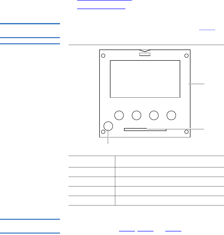
Chapter 5 Troubleshooting
Interpreting System LED Status
Quantum Scalar 50 User’s Guide 171
•Power Supply LED Status
•Tape Drive LED Status
Operator Control Panel
(OCP) LED Status 5The OCP has an LED indicator reporting the library state (see table 35).
Table 35 OCP LED States
System Controller Board
(SCB) LED Status 5The SCB contains LED indicators that reports the state of the SCB and
Fibre Channel port (see table 36, table 37, and table 38).
LED Status Problem/Status
Green solid The library is in an idle state.
Green flashing The library is busy.
Amber flashing The library is in an attention state.
Amber solid An error has occurred on the library.
Power button
OCP
LED
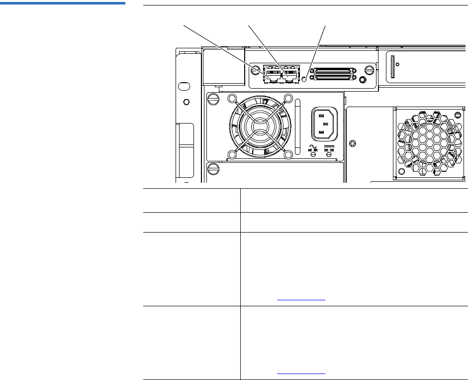
Chapter 5 Troubleshooting
Interpreting System LED Status
Quantum Scalar 50 User’s Guide 172
Table 36 SCSI SCB LED
LED Status Problem/Status
SCB LED Flashing SCB good. Communicating.
SCB LED solid • System busy.
• If the LED is solid for more than two minutes
and the library has been initialized, contact an
authorized Quantum field service engineer
see (“Contacts” on page xx).
SCB LED Off • System idle.
• If the LED is off for more than two minutes
and the library has been initialized, contact an
authorized Quantum field service engineer
see (“Contacts” on page xx).
SCB LED indicator
Internal network
Customer network
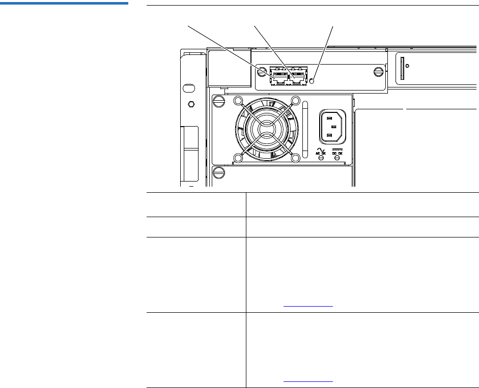
Chapter 5 Troubleshooting
Interpreting System LED Status
Quantum Scalar 50 User’s Guide 173
Table 37 Surrogate SCB LED
LED Status Problem/Status
SCB LED Flashing SCB good. Communicating.
SCB LED solid • System busy.
• If the LED is solid for more than two minutes
and the library has been initialized, contact an
authorized Quantum field service engineer
see (“Contacts” on page xx).
SCB LED Off • System idle.
• If the LED is off for more than two minutes
and the library has been initialized, contact an
authorized Quantum field service engineer
see (“Contacts” on page xx).
SCB LED indicator
Internal network
Customer network
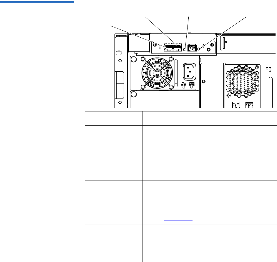
Chapter 5 Troubleshooting
Interpreting System LED Status
Quantum Scalar 50 User’s Guide 174
Table 38 Fibre Channel SCB
LED
LED Status Problem/Status
SCB LED Flashing SCB good. Communicating.
SCB LED solid • System busy.
• If the LED is solid for more than two minutes
and the library has been initialized, contact an
authorized Quantum field service engineer
see (“Contacts” on page xx).
SCB LED Off • System idle.
• If the LED is off for more than two minutes
and the library has been initialized, contact an
authorized Quantum field service engineer
see (“Contacts” on page xx).
Fibre Channel LED
solid
• Fibre Channel port has a good link.
Fibre Channel LED
Off
• Fibre Channel port is unplugged or does not
have a good link.
SCB LED indicator Fibre Channel LED indicator
Internal network
Customer network
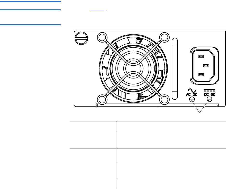
Chapter 5 Troubleshooting
Interpreting System LED Status
Quantum Scalar 50 User’s Guide 175
Power Supply LED Status 5The power supplies have an LED indicator reporting the power supply
state (see table 39).
Table 39 Power Supply LEDs
LED Status Problem/Status
AC OK solid green Power has been applied to the power supply and
is within specifications.
AC OK off The power supply is not attached to a power
source or the power source has failed.
DC OK solid green The power supply is providing DC power to the
library normally.
DC OK off The power supply has failed.
LEDs

Chapter 5 Troubleshooting
Interpreting System LED Status
Quantum Scalar 50 User’s Guide 176
Tape Drive LED Status 5The tape drive canisters have LED indicators reporting the tape drive
state (see table 40).
Table 40 Tape Drive LEDs
LED Status Problem/Status
Green flashing Drive good. Communicating.
Green solid Drive failed
Off No power to drive.
Left yellow on Fibre Channel port active.
Right yellow on Fibre Channel port active.
Left yellow LED
(Fibre Channel 1)
Green activity LED
Right yellow LED
(Fibre Channel 2)


Appendix A Specifications
Physical Specifications
Quantum Scalar 50 User’s Guide 178
Physical Specifications
Table 41 Unit Dimensions/
Weight
Width
Depth
Height
Weight
Table 42 Capacities
Scalar 50
19 in. (482 mm)
31 in. (762 mm.)
6.75 in. (171 mm)
87 lbs. (39 kg) with 2 drives, 2 magazines, and 0 cartridges
installed
Scalar 50
Number of Tape Drives Up to 2
Type of Tape Drives DLT-S4 (SCSI and nFC), HP and
Quantum LTO Gen 3, HP LTO
Gen 4 (SCSI and nFC)
Number of Tape Cartridges Up to 32 SDLT tape cartridges
Up to 38 LTO cartridges
Type of Tape Cartridges For use with:
•DLT-S4 drives: DLT-S4 media
• HP LTO Gen drives: HP and
Quantum LTO-3 and HP LTO-4
Ultrium cartridges
Number of Magazines Up to 2
Magazine Capacity Each magazine holds up to 15
SDLT tape cartridges or up to 18
LTO tape cartridges
Manual Access Facility Yes

Appendix A Specifications
Performance Specifications
Quantum Scalar 50 User’s Guide 179
Performance Specifications
Table 43 Performance
Specifications
Average Swap Time
Table 44 Library Performance
Scalar 50 (2 drives)
DLT-S4 48 TB 51.2 TB 864 GB/hr
Quantum
LTO Gen 3
28.8 TB 30.4 TB 490 GB/hr
HP LTO
Gen 3
28.8 TB 30.4 TB 1.1 TB/hr
HP LTO
Gen 4
57.6 60.8 1.7
* Assuming 2:1 compression ratios
Robot Mounted Bar Code
Reader
Yes
Scalability Yes
Scalar 50
Less than 14 seconds
Tape
Drive
Data Capacity
(Excluding
Fixed Slots)*
Maximum Data
Capacity
(Including
Fixed Slots)*
Maximum
Data
Throughput* Host Interfaces
Ultra 320 SCSI and
Native Fibre Channel
LVD Ultra 3 SCSI and
Native Fibre Channel
LVD Ultra 3 SCSI and
Native Fibre Channel
LVD Ultra 3 SCSI, SAS,
and Native Fibre
Channel
Scalar 50

Appendix A Specifications
Reliability Specifications
Quantum Scalar 50 User’s Guide 180
Reliability Specifications
Table 45 Reliability
Specifications MSBF
MTTR
Tape Drive Specifications
Table 46 Tape Drive
Specifications
Scalar 50 = 1,000,000 swaps
Less than 30 minutes
Drive
Type
Native Mode With 2:1 Compression
Transfer Rate Capacity Transfer Rate Capacity
DLT-S4 3600 MB/min 800 GB 7200 MB/min 1600 GB
HP LTO
Gen 3
4800 MB/min. 400 GB. 9600 MB/min. 800 GB
HP LTO
Gen 4
4800 MB/min. 800 GB. 12000 MB/
min.
1.6 TB

Appendix A Specifications
Environmental Specifications
Quantum Scalar 50 User’s Guide 181
Environmental Specifications
Table 47 Power
Electrical
Input
Tolerances
Voltage
Power
Table 48 Climate
Temperature
Humidity
Altitude
Noise Levels 1The work area noise generated by the library amounts to 57.4 dB(A).
Deutch: Die arbeitsplatzbezogene Geräuschemission des Gerätes beträgt
57.dB(A).
SCSI Specifications
LVD SCSI configurations have a maximum allowable bus length of 12
meters (39 feet). To determine the cable length of the bus, measure the
lengths of the SCSI cables connecting each device to that bus and add
those lengths together. To that total length, add 12.25 inches (31.10 cm)
for the internal SCSI cable length of each SCSI tape drive.
Scalar 50
90-264 VAC, 47-63 Hz
300W (average)
Temperature
(Operating)
Temperature
(Non-Operating)
+50°F to 95°F
(+10°C to +35°C)
-40°F to +149°F
(-40°C to +65°C)
20% to 80%
non-condensing
10% to 90%
non-condensing
-500 to +10,000 feet
(-152 to +3,048 meters)
-500 to +40,000 feet
(-152 to +12,192 meters)

Quantum Scalar 50 User’s Guide 182
Appendix B
BSDLTtape Cartridge
Maintenance
This appendix provides guidelines for handling SDLT cartridges and
visually inspecting cartridges if necessary.
Handling DLTtape Cartridges
• Always keep each tape cartridge in its protective plastic case when it
is not in the library.
• When carrying tape cartridges in their cases, always orient the cases
so that the grooves in the cases interlock. This prevents the cases from
slipping apart and falling.
• Never stack more than five cartridges on top of each other.
• Always observe the proper environmental conditions for the storage
of tape cartridges. Refer to the cartridge reference card supplied with
each cartridge.
• When placing tape cartridges in archival storage, make sure you
stand each tape cartridge vertically.
• Avoid placing tape cartridges near any sources of high intensity
magnetic fields, such as computer monitors or electric motors.

Appendix B SDLTtape Cartridge Maintenance
Visual Inspection of DLTtape Cartridges
Quantum Scalar 50 User’s Guide 183
• Never apply adhesive labels or POST-IT notes to the top, side, or
bottom of your DLTtape cartridge. Only use the user slide- in type
label provided with each cartridge and slide it over the label slot on
the cartridge.
• Do not carry cartridges loosely in a box or any other container.
Allowing cartridges to bang together exposes them to unnecessary
physical shock.
• Do not touch or allow direct contact with tape or tape leader. Dust or
natural skin oils can contaminate the tape and impact tape
performance.
• Do not expose the tape cartridge to moisture or direct sunlight.
• Do not insert a dropped or damaged cartridge into a DLTtape drive
without, at the very least, a thorough visual inspection (see Visual
Inspection of DLTtape Cartridges). A dropped cartridge may have
dislodged, loosened, or damaged internal components.
Visual Inspection of DLTtape Cartridges
When To Visually Inspect
a DLTtape Cartridge 2It is important to visually inspect a DLTtape cartridge under the
following circumstances:
• Whenever you change or load a new tape cartridge
• If the tape cartridge has been dropped or subjected to a physical
shock
• If a DLTtape drive becomes inoperable after loading the tape
cartridge
• If you receive a shipment of tape cartridges that shows any sign of
being damaged
Visual Inspection
Procedure 2To visually inspect a DLTtape cartridge:
1Check the cartridge for any obvious cracks or other physical damage.
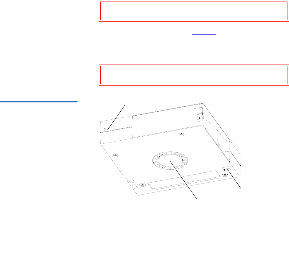
Appendix B SDLTtape Cartridge Maintenance
Visual Inspection of DLTtape Cartridges
Quantum Scalar 50 User’s Guide 184
2Gently shake the tape cartridge. Listen for any rattling of loose pieces
inside the cartridge.
Caution: If you hear anything loose inside the cartridge, do not
use the cartridge.
3Locate the reel lock openings (see figure 99) and verify that you can
see the reel locks.
The reel locks are small plastic tabs near the center of the reel lock
openings. They can be broken if the cartridge is dropped.
Caution: If the reel locks are not visible, do not use the
cartridge.
Figure 99 Location of the Reel
Locks and the Hub
Reel lock
opening
Reel lock
opening
Spring-
loaded hub
4Verify that the spring-loaded hub (see figure 99) is centered within
the circular opening in the tape cartridge.
5Gently press the hub, then release it. Make sure the hub springs back
into place and is still centered within its circular opening.
6Open the tape cartridge door (see figure 100):
aGently press up on the tab at the right side of the tape cartridge
door.
bSwing the door open.
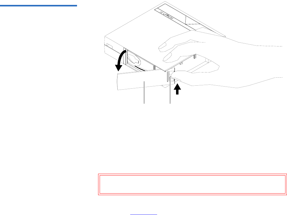
Appendix B SDLTtape Cartridge Maintenance
Visual Inspection of DLTtape Cartridges
Quantum Scalar 50 User’s Guide 185
Figure 100 Opening the Tape
Cartridge Door
Tape
cartridge
door
Tab
7Verify that:
• The tape is wound tightly on the reel
• The tape leader loop is sticking up about an eighth of an inch
• The tape leader loop is not bent or torn
Caution: If any of the above conditions are not met, do not use
the cartridge.
8Check for proper operation of the tape cartridge’s write-protect
switch (see figure 101).
The switch should snap back and forth, and the orange tab should be
visible when the switch is in the write-protected position.
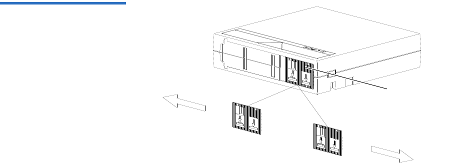
Appendix B SDLTtape Cartridge Maintenance
Visual Inspection of DLTtape Cartridges
Quantum Scalar 50 User’s Guide 186
Figure 101 Write Protect
Switch
Write-protect
switch

Quantum Scalar 50 User’s Guide 187
Appendix C
CInstalling the Scalar 50
Library
This appendix explains how to install the Quantum Scalar 50 library.
Selecting an Installation Location
When choosing an installation site for the Scalar 50 library, consider the
following requirements:
•Rack Space Requirements
•Environmental Conditions
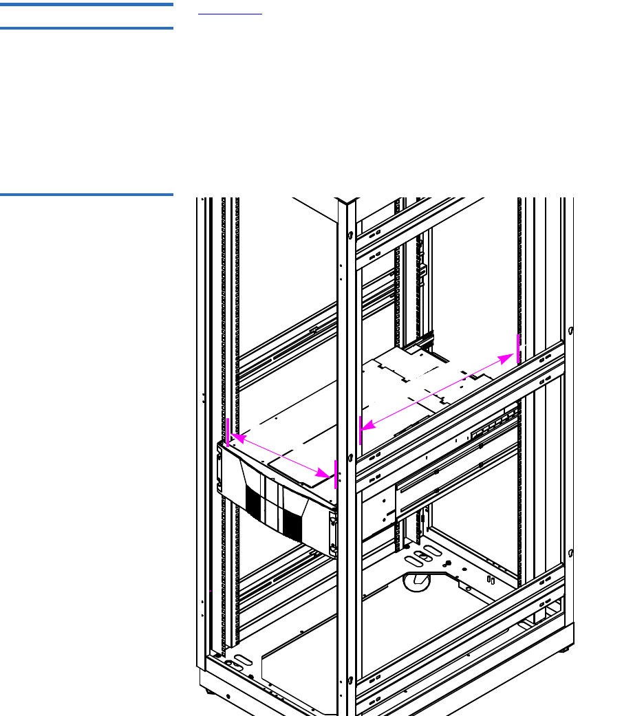
Appendix C Installing the Scalar 50 Library
Selecting an Installation Location
Quantum Scalar 50 User’s Guide 188
Rack Space Requirements 3
Figure 102 shows the minimum rack space required by the Scalar 50
library.
• Depth - 31 in (76.2 cm)
• Width - 19 in (48.3 cm)
• Height - 6.75 (17 cm)
• Weight - 52 lbs (23.6 kg)
• Clearance behind library - 4 in (10 cm) behind unit for proper air flow
Figure 102 Rack Space
Requirements
31 in to 36 in (78.8 to 91 cm
19 in (48.3 cm)

Appendix C Installing the Scalar 50 Library
Preparing for the Installation
Quantum Scalar 50 User’s Guide 189
Environmental
Conditions 3Refer to appendix A on page 177 for environmental condition
information.
Preparing for the Installation
Before you begin the installation procedure in this section, make the
following preparations as described in this section:
•Providing Necessary Tools and Equipment
•Taking ESD Precautions
Providing Necessary
Tools and Equipment 3Provide the following tools for installing the Scalar 50 library:
• 3 mm Allen wrench
• 2.5 mm Allen wrench
• #1 flat blade screwdriver
• Antistatic wrist strap included in accessory kit
Taking ESD Precautions 3Some components within the Scalar 50 library contains static-sensitive
parts. To avoid damaging these parts while performing installation
procedures, always observe the following precautions:
• Keep the library turned off during all installation procedures.
• Use an antistatic wrist strap (included in the accessory kit).
• Keep static-sensitive parts in their original shipping containers until
ready for installation.
• Do not place static-sensitive parts on a metal surface. Place them
inside their protective shipping bag or on an antistatic mat.
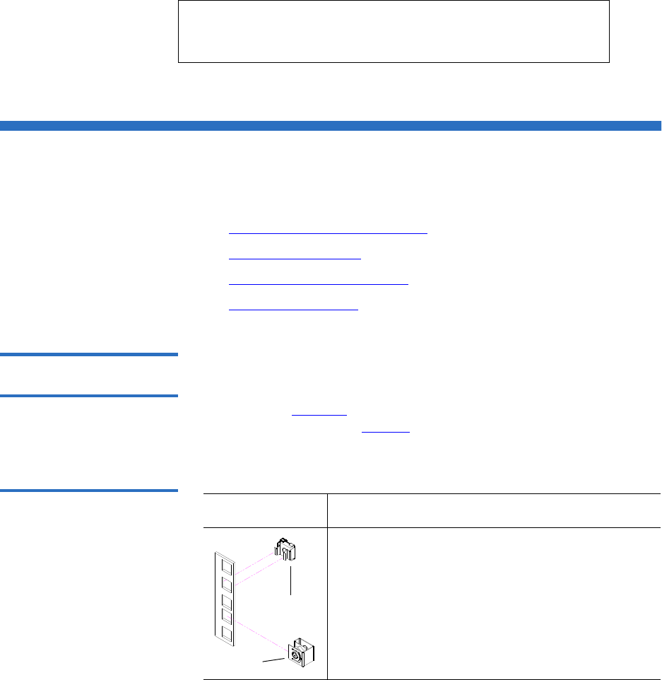
Appendix C Installing the Scalar 50 Library
Installing the Library
Quantum Scalar 50 User’s Guide 190
• Avoid touching connectors and other components.
Installing the Library
Installing a Scalar 50 library in a rack consists of the following steps:
•Locating the Mounting Position
•Installing the Library
•Loading the Tape Cartridges
•Initial Configuration
Locating the Mounting
Position 3The Scalar 50 library is designed to fit in a standard 19 inch wide rack.
It is important to the library installation to locate the hole pattern in the
rack rails (see figure 50). The library must be installed at the beginning of
the hole pattern. Refer to table 49 for information on common rack hole
types.
Table 49 Rack Hole Types
Note: Dry climates and cold-weather heating environments
have lower relative humidity and are more likely to
produce static electricity.
Figure Description
Square rack holes are the most common type of
rack holes. They can accept either cage nuts which
mount from the back of the rail or clip nuts which
clip on from the side of the rack rail.
Cage nut
Clip nut
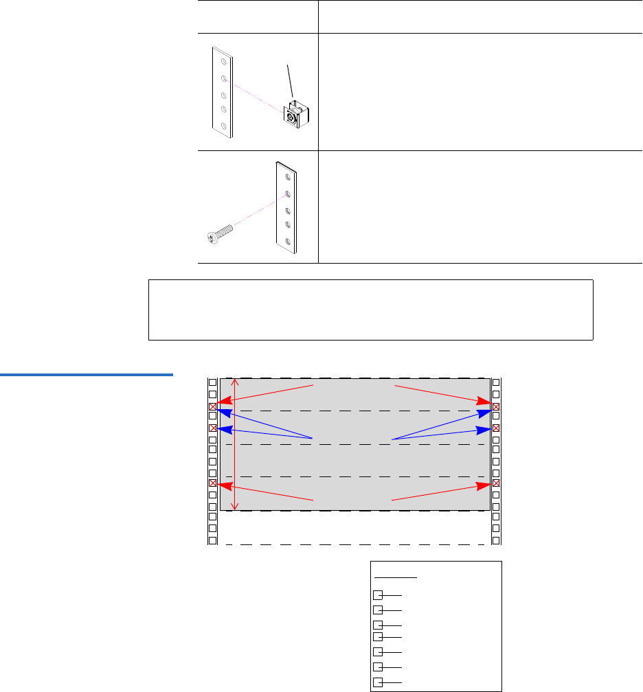
Appendix C Installing the Scalar 50 Library
Installing the Library
Quantum Scalar 50 User’s Guide 191
Table 50 Scalar 50 Rail Hole
Patterns and Mounting
Positions
.625 in (15.9 mm)
.625 in (15.9 mm)
.5 in (12.7 mm)
.625 in (15.9 mm)
.625 in (15.9 mm)
Top of rack
.312 in (7.92 mm)
.5 in (12.7 mm)
Hole pattern
The marks above (X)
indicate the location of
mounting hardware on the
rack rails. Ensure that any
necessary mounting
hardware is installed on the
rack rails prior to installing
the chassis.
1 Scalar 50 System (4U)
1U = 1.75
4U
Front panel
screws
Back panel
screws
Front panel
screws
Through holes require clip nuts to accept
mounting hardware.
Threaded holes require neither cage or clip nuts to
accept mounting hardware.
Note: The rails within the rack have a hole pattern that repeats
throughout the rail. X marks the screw positions. Install nut
clips (included in the accessory kit) on the rails if necessary.
Figure Description
Clip nut
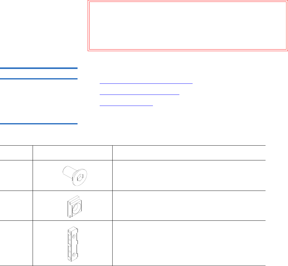
Warning: If the rack is empty at the time of installation, do NOT
install the Scalar 50 library too high in the rack. The
weight of the library may cause the rack to become “top
heavy” and unstable if installed in the top of an empty
rack. Begin installing the Scalar 50 library from the bottom
of the rack if more than one library is installed in the rack.
Appendix C Installing the Scalar 50 Library
Installing the Library
Quantum Scalar 50 User’s Guide 192
Installing the Library 3Installing the Scalar 50 library consists of the following steps:
•Installing the Rack Mount Shelves
•Installing the Library Chassis
•Cabling the Library
Table 51 Library Mounting
Hardware
Qty Figure Description
16 Allen head screws (M5 x 10) for shelf assembly
8 T- nuts (M5)
4 metric
and 4
standard
Rail adapters (both metric and standard holes are
included, 8 total adapters)
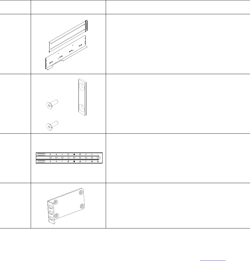
Appendix C Installing the Scalar 50 Library
Installing the Library
Quantum Scalar 50 User’s Guide 193
Installing the Rack Mount Shelves 3
1Assemble the rack mount shelves by (see figure 104):
2 Right and left support shelves (left shown)
4 sets Front and back rail mounting hardware(M5 x 12 allen
screws and mounting plates)
2 sets Back bracket hardware (M5 x 8 allen screws and
mounting plate)
2 sets Back clamp hardware (M5 x 10 and back clamp)
Qty Figure Description
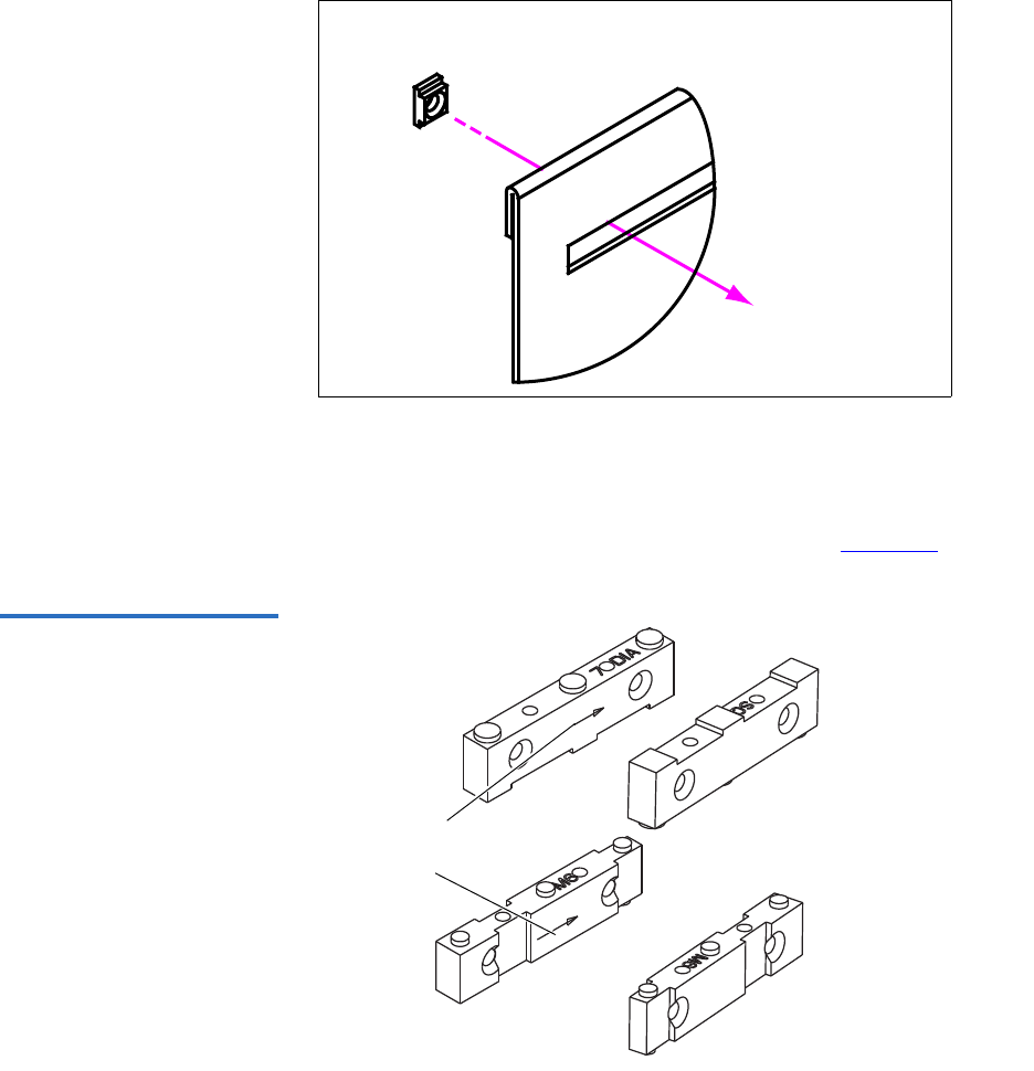
Appendix C Installing the Scalar 50 Library
Installing the Library
Quantum Scalar 50 User’s Guide 194
aLoosely attach the adjustable shelves (right and left) with 4 M5 x
10 Allen screws and T-nuts.
bAttach the appropriate rail adapter to the front and back of the
rack mount shelves (right and left) with 4 M5 x 10 Allen screws
(each rail adapter is marked with the specific hole type
supported, either metric or standard). The rail adapters have
arrows indicating the proper orientation (see figure 103).
Figure 103 Rail Adapter
Orientation
Keep the arrow up for
correct orientation
Note: T-Nuts must be oriented so they fit in the grooves of
the shelves.
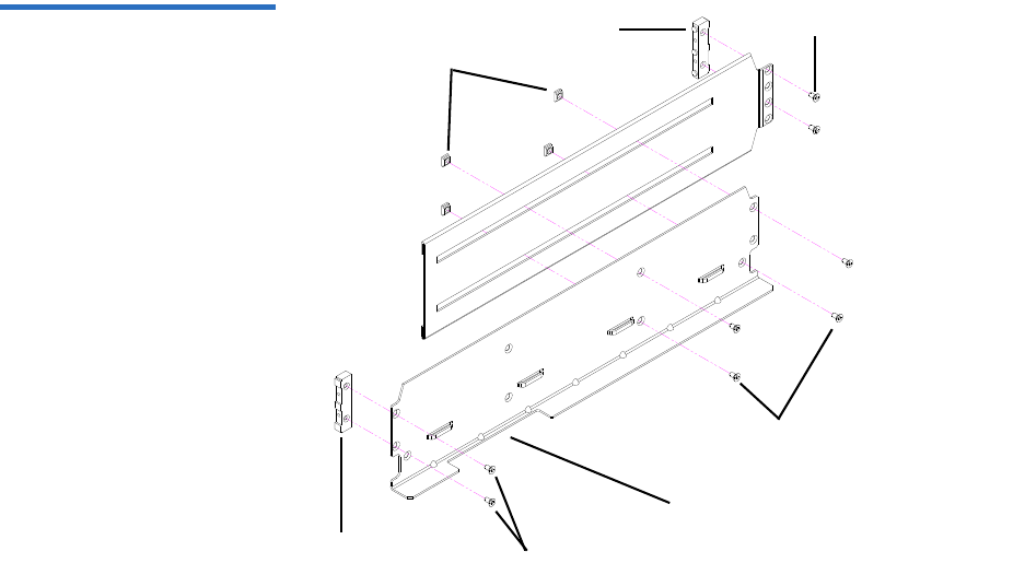
Appendix C Installing the Scalar 50 Library
Installing the Library
Quantum Scalar 50 User’s Guide 195
Figure 104 Assembling the
Left-Hand Rack Mount Shelves
Allen screws
Rail adapter
T-nuts
Left shelf
Rail adapter Allen screws
Allen screws
FlexLink™ opening
located towards the
front for the left-hand
shelf
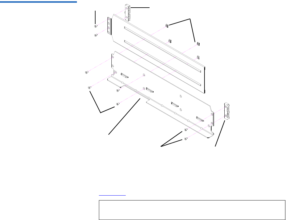
Appendix C Installing the Scalar 50 Library
Installing the Library
Quantum Scalar 50 User’s Guide 196
Figure 105 Assembling the
Right-Hand Rack Mount
Shelves
Right shelf
T-nuts
Rail adapter
Allen screws
Allen screws Rail adapter
Allen screws
FlexLink opening
located towards the
back for the right-hand
shelf
2Install the left and right rack mount shelves into the rack (the rack
mount shelves adjust 27 in. to 36 in.) and secure with a mounting
plate and 2 M4 x 12 Allen screws at the front and back of the rack (see
figure 106).
Note: The rack mount shelves must be installed on the inside
rack rails.
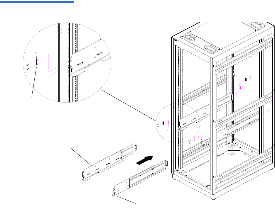
Appendix C Installing the Scalar 50 Library
Installing the Library
Quantum Scalar 50 User’s Guide 197
Figure 106 Installing the Rack
Mount Shelves
Mounting
plate
M4 x 12 Allen
screws
Left rack mount shelf
Right rack mount shelf
Front of rack
3Once the rack mount shelves are secured to the rack, tighten the
Allen screws securing the adjustable shelves together.

Appendix C Installing the Scalar 50 Library
Installing the Library
Quantum Scalar 50 User’s Guide 198
Installing the Library Chassis
Warning: The Scalar 50 weighs approximately 65 lbs (29 kg) without
power supplies or tape drives. At least two people are
required to lift and install either library.
3
1The back mounting brackets are lettered (A through I so the correct
mounting position is easily determined. The mounting positions
differ depending on the depth of the rack (see table 52).
Table 52 Back Mounting
Bracket Orientation
Once the location is determined, attach the back brackets to each side of
the library with four M5 x 8 Allen screws (see figure 107)
Rack Depth Mounting Position
>27 to 28 in. Use holes A and C
>28 to 29 in. Use holes B and D
>29 to 30 in. Use holes A and C
>30 to 31 in. Use holes B and D
>31 to 32 in. Use holes C and E
>32 to 33 in. Use holes D and F
>33 to 34 in. Use holes E and G
>34 to 35 in. Use holes F and H
>35 to 36 in. Use holes G and I
Note: Use the shortest depth number. For example, if the
measurement is 34 in., use holes E and G.

Appendix C Installing the Scalar 50 Library
Installing the Library
Quantum Scalar 50 User’s Guide 199
Figure 107 Back Mounting
Brackets
Right-hand back
bracket shown.
Back mounting
bracket
Allen
screws
2Install the library into the rack as shown (see figure 107)
Warning: The Scalar 50 weighs approximately 65 lbs (29 kg)
without power supplies or tape drives. At least two
people are required to lift and install either library.
.
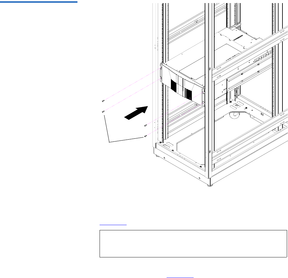
Appendix C Installing the Scalar 50 Library
Installing the Library
Quantum Scalar 50 User’s Guide 200
Figure 108 Installing the
Scalar 50 in the Rack
PHILLIPS screws
3Secure the back of the library to the rack with two mounting clamps
and two Allen screws on each clamp. The mounting clamps are
oriented differently depending on the depth of the rack (see
figure 109).
4Secure the mounting clamps to the rack rails with two PHILLIPS
screws on each side (see figure 109).
Note: If the rack depth is 27 to 30 in., the long portion of the
clamp is mounted to the back. If the rack depth is 30 to 36
in., the long portion is mounted to the front.
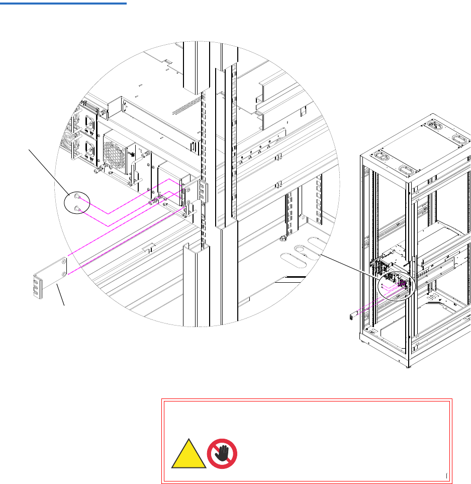
Appendix C Installing the Scalar 50 Library
Installing the Library
Quantum Scalar 50 User’s Guide 201
Figure 109 Securing the Back
of the Library
Right-hand back
bracket shown.
Allen
screws
Long
portion
5To install the tape drives into the library:
Warning: Hazardous Moving Parts.
Keep Fingers and Other Body
Parts Away When Removing
and Installing Tape
Drives.
Warning: Hazardous Moving Parts.
Keep Fingers and Other Body
Parts Away When Removing
and InstallingTape
Drives.
Warnung: Gefährliche bewegliche
Teile. Halten Sie die
Finger und andere
Körperteile weg, wenn
Sie Bandlaufwerke
entfernen und
anbringen.
Warnung: Gefährliche bewegliche
Teile. Halten Sie die
Finger und andere
Körperteile weg, wenn
Sie Bandlaufwerke
entfernen und
anbringen.
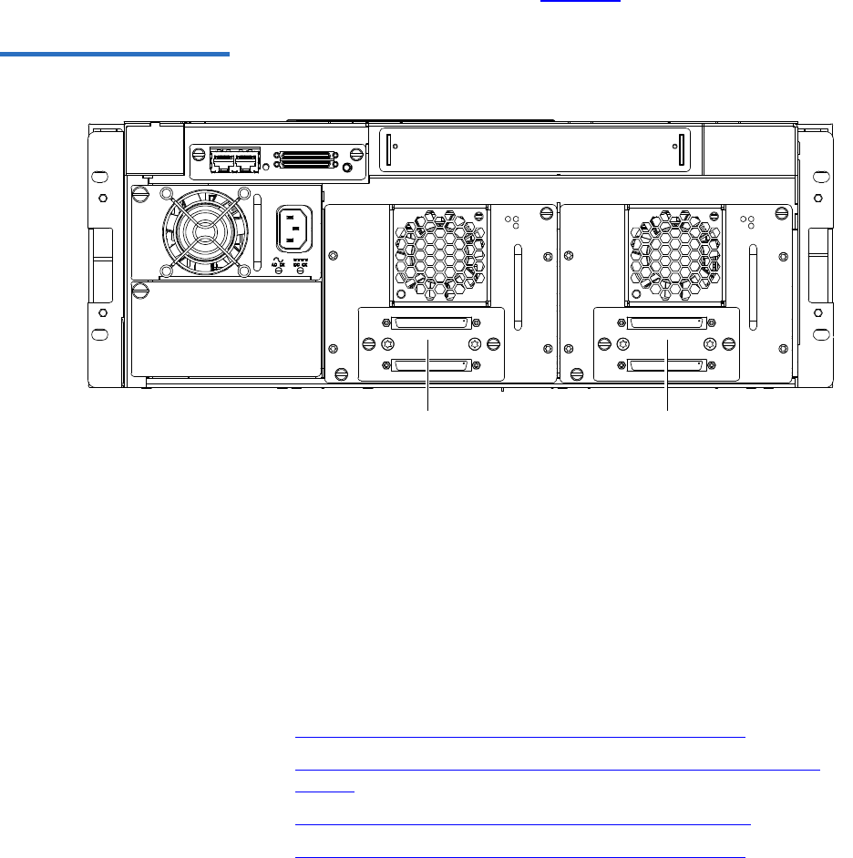
Appendix C Installing the Scalar 50 Library
Installing the Library
Quantum Scalar 50 User’s Guide 202
aInsert the tape drive into the drive bay slowly until the
connectors are seated (see figure 110).
Figure 110 Scalar 50 Tape
Drive Numbering
Tape
drive 2
Tape
drive 1
bTighten the tape drive captive screws using a flat blade
screwdriver.
cRepeat these steps to install another tape drive in a different
location, if desired.
The library chassis is installed in the rack.
Cabling the Library 3
Connect the SCSI cables and jumpers as shown in the following figure:
•Scalar 50 Cable Configuration (SCSI Full Height Drives)
•Scalar 50 Cable Configuration (Native Fibre Channel Full Height
Drives)
•Scalar 50 Cable Configuration (SCSI Half-Height Drives)
•Scalar 50 Cable Configuration (SAS Half-Height Drives)
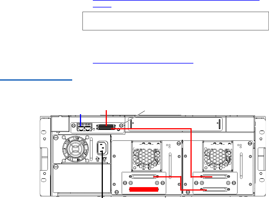
Appendix C Installing the Scalar 50 Library
Installing the Library
Quantum Scalar 50 User’s Guide 203
•Scalar 50 Cable Configuration (Native Fibre Channel Half-Height
Drives)
Stacked Configuration 3
•Scalar 50 Cable Configuration (Stacked)
Figure 111 Scalar 50 Cable
Configuration (SCSI Full Height
Drives)
Back of Library
SCSI hostEthernet
Power
System Controller Board
Tape drive 1Tape drive 2
Note: Quantum ships sufficient SCSI cables and terminators with the
libraries to set up two-drives per SCSI bus.
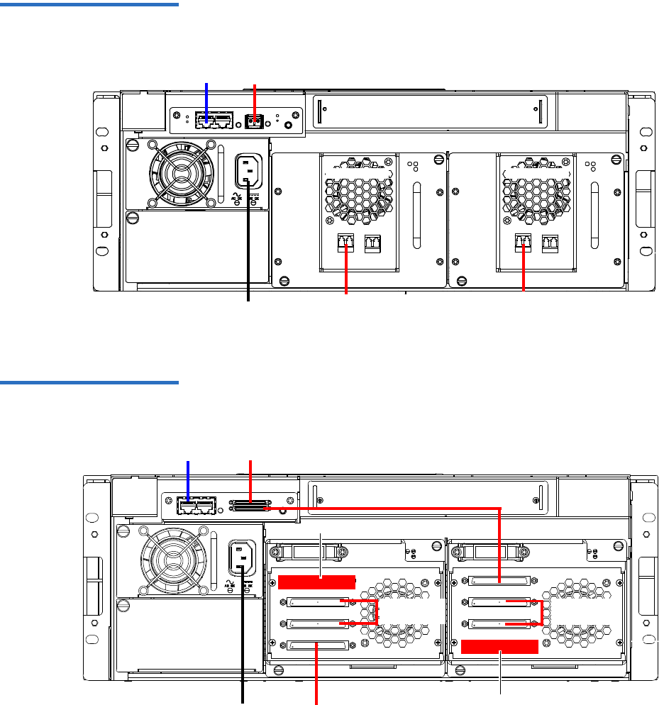
Appendix C Installing the Scalar 50 Library
Installing the Library
Quantum Scalar 50 User’s Guide 204
Figure 112 Scalar 50 Cable
Configuration (Native Fibre
Channel Full Height Drives)
Back of Library
Ethernet
Power
Tape drive 2 Tape drive 1
LTO Tape drives
shown. SDLT drives
have a single FC port
Fibre Channel
host/SAN
Fibre Channel
host/SAN
Fibre Channel host/SAN
Figure 113 Scalar 50 Cable
Configuration (SCSI Half-
Height Drives)
Ethernet
Power
Back of Library
SCSI host
Terminator
Tape drives
1 and 2
Tape drives
3 and 4
SCSI host
Terminator
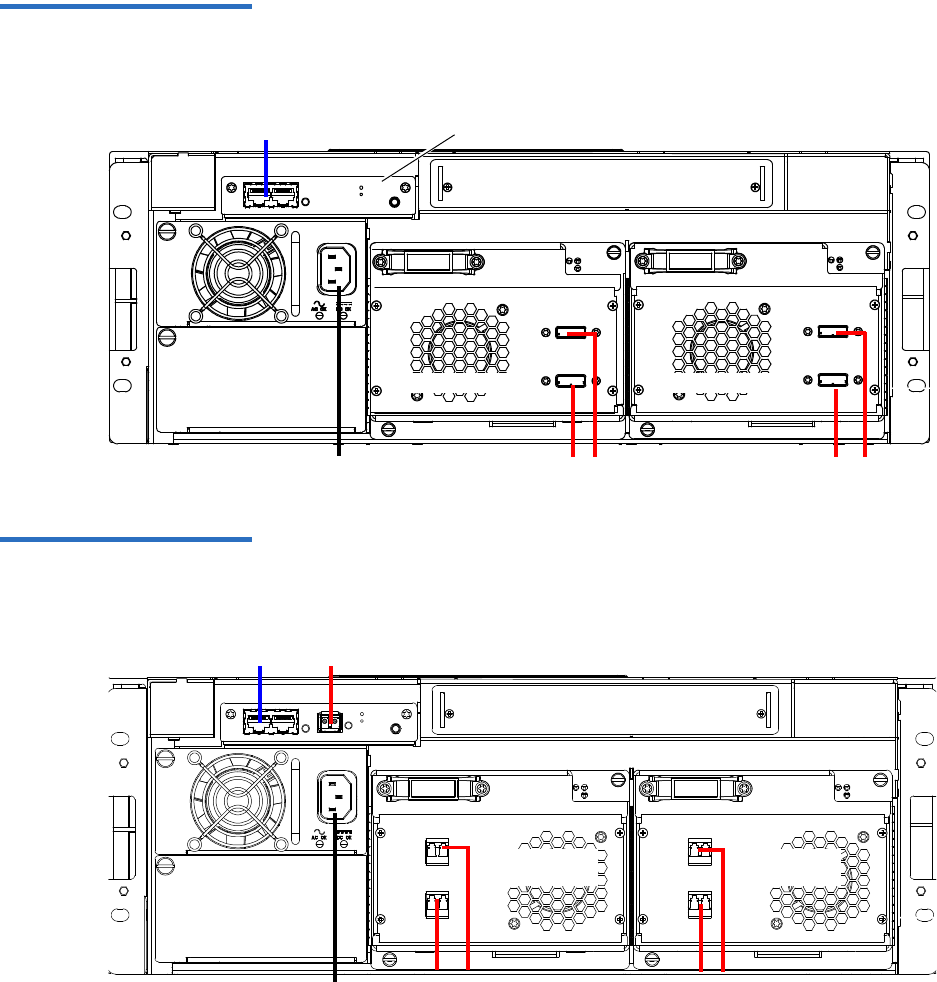
Appendix C Installing the Scalar 50 Library
Installing the Library
Quantum Scalar 50 User’s Guide 205
Figure 114 Scalar 50 Cable
Configuration (SAS Half-Height
Drives)
Back of Library
Ethernet
Power SAS hosts
Tape drives 1
Surrogate Mode System
Controller Board ONLY
SAS hosts
Tape drives 2
Figure 115 Scalar 50 Cable
Configuration (Native Fibre
Channel Half-Height Drives)
Back of Library
Ethernet
Power Fibre Channel
host/SAN
Fibre Channel
host/SAN
Tape drives
1 and 2
Tape drives
3 and 4
Fibre Channel host/SAN
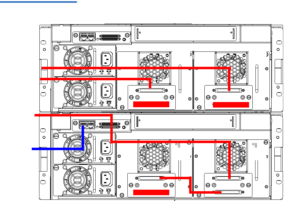
Appendix C Installing the Scalar 50 Library
Installing the Library
Quantum Scalar 50 User’s Guide 206
Figure 116 Scalar 50 Cable
Configuration (Stacked)
Scalar 50 (master library)
Scalar 50 (slave library)
Host computer
Tap e
drive 2
Tape
drive 1
Tape
drive 1
Tap e
drive 2
Host computer
Ethernet
The library
host and
Ethernet
network are
connected only
to the Master
library.

Appendix C Installing the Scalar 50 Library
Installing the Library
Quantum Scalar 50 User’s Guide 207
Loading the Tape
Cartridges 3Before operating the library, load the appropriate tape cartridges (LTO
and/or SDLT) into the library starting with the left-hand magazines
(refer to Preparing the Library for Operation on page 30 for more
information on tape cartridges).
Initial Configuration 3Initially configuring the library consists of the following steps:
•Turning on the Library
•Setting the Date and Time
•Setting Network Information
Turning on the Library 3
To turn on the library:
1Verify that:
• Power cables are firmly in place
• All doors are closed
2Turn on the power switch located in the lower left-hand corner of the
OCP (see figure 117).
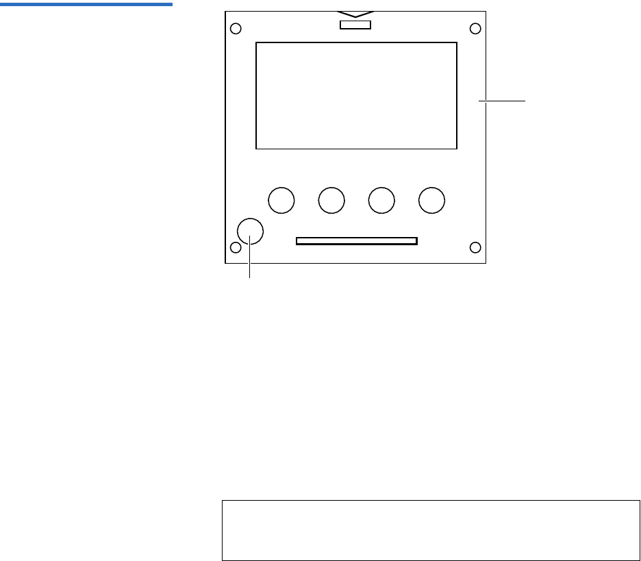
Appendix C Installing the Scalar 50 Library
Installing the Library
Quantum Scalar 50 User’s Guide 208
Figure 117 Turning On the
Library
Power button
OCP
3When the library powers on for the first time after the hand has been
parked for shipping, the OCP asks you:
“Hand Restraint Found. Please Remove! Starting Shutdown...”
4The OCP then displays:
“Doors opened, magazines released, pull magazines out before power
shutoff.”
The library waits approximately 30 seconds for you to open the
doors, remove both magazines from the library, and remove the hand
restraint.
5After the library has powered down, remove the hand restraint by
completing the following steps (see the Scalar 50 Quick Start Guide for
more information):
aRemove the two thumb screws securing the hand restraint to the
base of the library.
Note: If you are unable to remove the magazines before the
library shuts down. Turn on the library power and repeat
the steps above.

Appendix C Installing the Scalar 50 Library
Installing the Library
Quantum Scalar 50 User’s Guide 209
bRemove the hand restraint from the library.
Caution: Avoid touching the printed circuit board.
Caution: When removing the hand restraint, ensure that the
robotics umbilical cable is lying down in the correct
position inside the platform and not across the
robotics track.
cStore the thumb screws and the restraining bolt in the hand
restraint.
dInstall the tape cartridge magazines.
eClose the front doors.
6Turn on the library by pushing power button located on the bottom
left-hand corner of the OCP (see figure 117).
7The OCP asks you:
“Are the Shipping Restraints Removed?” (YES or NO).
8Press YES to continue.
9The OCP asks again:
“Are you sure the Hand & Thumb Screw Restraints have been
Removed?” (YES or NO).
10 Press YES to continue. The library continues the boot process. When
complete, the Home screen displays.
11 Press Setup from the Home screen. The OCP displays the Setup
screen (see figure 118):
Note: If the library encounters difficulties during the boot
process, there may be obstructions inside the library. The
the OCP will display: "Please Remove Restraining Bolt, or
Hand Restraint. See User's Guide.” Shut down the library,
open the doors with the emergency access tool and check
for obstructions. Be sure to check for the restraining bolt
on the left side of the cabinet.

Appendix C Installing the Scalar 50 Library
Installing the Library
Quantum Scalar 50 User’s Guide 210
Figure 118 Setup Screen
Enter
12 From the Setup screen, use the up and down arrows to highlight
Cabinet and press Enter.
The Cabinet screen displays (see figure 119):
Figure 119 Library Options
Screen
13 The Stack role screen allows you to configure the library as a
“Master” or “Slave” in a multiple library stack. The library is
configured “Stand alone” by default. If this is a multiple library stack,
use the up and down arrows to highlight Stack role and press Enter
displays the following information about the library:
Note: All Scalar 50 libraries must have FULL capacity before
configuration as a stack is possible. PX502 libraries in a
stack are considered fully licensed. Configure each unit
that will be stacked as a stand alone unit and enable Full
capacity through the remote management pages (see
Library on page 125). After full capacity is enabled, change
the stack role(s) accordingly to create the multiple library
stack.
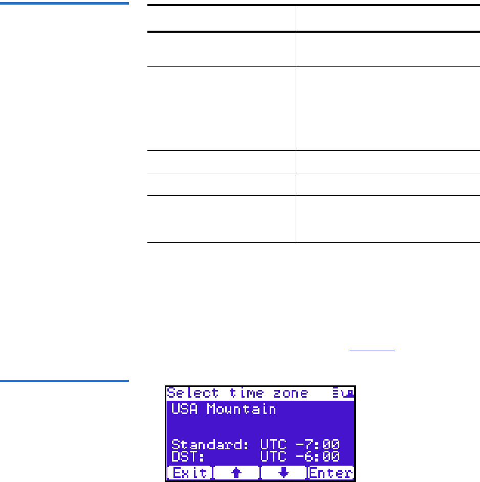
Appendix C Installing the Scalar 50 Library
Installing the Library
Quantum Scalar 50 User’s Guide 211
Table 53 Setting Up the
Cabinet
Setting the Date and Time 3
To set the date and time:
1From the Setup screen, use the up and down arrows to highlight
Date and Time and press Enter.
The Date and Time screen displays (see figure 120):
Figure 120 Date and Time
Screen
The Date and Time screen displays the following information about
the library:
Cabinet Options Description
Host bus Sets the SCSI ID for both the library
and tape drives.
Stack role Assigns the library stack role as
Master, Slave, or Stand alone. There
can be only one Master library in a
multiple stack. Once configured as a
slave, all library OCP functions can be
controlled via the Master library OCP.
Left load port Enables or disables the left load port
Right load port Enables or disables the right load port
Drive FUP from tape Allows you to perform a tape drive
firmware update from a firmware
update tape cartridge.
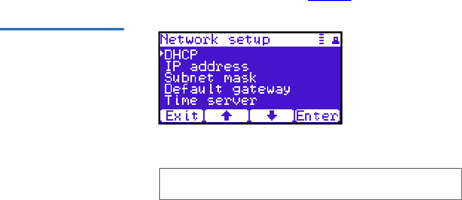
Appendix C Installing the Scalar 50 Library
Installing the Library
Quantum Scalar 50 User’s Guide 212
2Use the up and down arrows to view or edit the date and time
information. Press Enter to accept the new settings.
3When you are finished viewing/editing the date and time
information, press Exit to return to the Setup screen.
Setting Network Information 3
To view or edit the network information:
1From the Setup screen, use the up and down arrows to highlight
Network and press Enter.
2The Network screen displays (see figure 120):
Figure 121 Network Screen
The Network screen allows you to view or edit the following network
settings:
•DHCP (default setting)
•IP address
•Subnet mask
• Default gateway
3Use the up and down arrows to select the network setting you wish
to view or edit and press Enter.
When you are finished viewing/editing the network information,
press Exit to return to the Setup screen.
Note: The network settings (IP address, subnet mask, and
default gateway) are only active when DHCP is disabled.

Appendix C Installing the Scalar 50 Library
Emergency Library Access
Quantum Scalar 50 User’s Guide 213
4For the network information such as the IP address to be active, you
must reboot the library by holding down the power button located on
the front of the library (see figure 117).
The library shuts down.
5Push the power button to start the library.
The Scalar 50 tape library is initially configured and ready for use.
Emergency Library Access
Use the following procedure to gain access to the tape cartridge
magazines in case of an emergency and the library power is not available.
1Put on an antistatic wrist strap and clip it to the library chassis
(example: a captive screw on the tape drive cover plates).
Caution: Take standard ESD precautions when performing this
procedure.
2Insert the door release tool included with the accessory kit into the
release holes and trip the magazine door release for both the right
and left magazine doors (see figure 122).
The magazine access doors open.
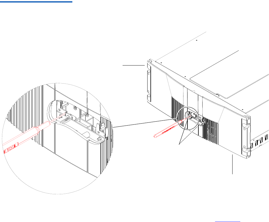
Appendix C Installing the Scalar 50 Library
Emergency Library Access
Quantum Scalar 50 User’s Guide 214
Figure 122 Opening the Right
and Left Magazine Access
Doors
Right magazine door
Door releases
Left magazine door
3Insert the door release tool that is included in the library accessory kit
into the magazine release hole and trip the magazine release to
remove the each magazine from the library (see figure 123). Remove
both magazines from the library.
The tape cartridge magazines are now accessible.
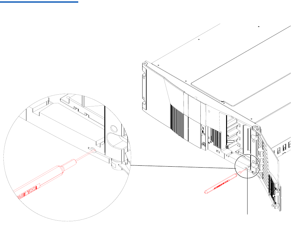
Appendix C Installing the Scalar 50 Library
Emergency Library Access
Quantum Scalar 50 User’s Guide 215
Figure 123 Removing the
Magazines
Magazine release

Quantum Scalar 50 User’s Guide 216
Appendix D
DRepacking the Scalar 50
Library
This document explains how to repack the Quantum Scalar 50 library.
Follow these instructions carefully to ensure the library is shipped
properly.
Caution: This procedure requires the packing materials originally
sent with the library for proper shipment. If you do not
have the library packing materials, contact Quantum
customer support for replacement packaging (800) 284-
5101.
This procedure consists of the following steps:
•Removing the Library from the Rack
•Installing the Internal Shipping Restraints
•Packing the Library for Shipment
Note: All Scalar 50 documentation is located on the Scalar 50
Documentation CD included in the library accessory kit.

Appendix D Repacking the Scalar 50 Library
Removing the Library from the Rack
Quantum Scalar 50 User’s Guide 217
Removing the Library from the Rack 4
To remove the Scalar 50 library from the rack:
1Using the OCP, open the front doors, remove both tape cartridge
magazines, and remove any tape cartridges from the fixed bins or
FlexLink™ (refer to the Quantum Scalar 50 User’s Guide PN 81-81768
for information on OCP operation and bin locations).
After removing the tape cartridge magazines and closing the doors,
the library inventories all possible tape cartridge locations
(magazines, fixed slots, Flexlink, and tape drives). This process takes
several minutes.
2From the Library Operations screen on the OCP, select Park for
Shipping. The library shuts down automatically.
3From the back of the library, disconnect all power, Ethernet, and SCSI
cables from the library and note their locations for later reinstallation.
Warning: This unit has more than one power supply cord.
Disconnect all power supply cords before servicing to
avoid electric shock.
4To remove the library chassis from the rack (see figure 124):
fLoosen the captive screws securing the tape drives to the chassis
and remove the tape drive(s) from the back of the library.
Note: You must remove all tape cartridges from the library prior
to parking the library robotics for shipment.
Note: If there are tape cartridges in the library, the system will
NOT park the library robotics. You must remove all tape
cartridges from the system prior to parking the library
robotics.
Note: Refer to the Scalar 50 Quick Start Guide (PN 81-81767) for
additional Scalar 50 rack mount information.

Appendix D Repacking the Scalar 50 Library
Removing the Library from the Rack
Quantum Scalar 50 User’s Guide 218
gLoosen the captive screw securing the power supplies to the
chassis and remove the power supplies from the back of the
library.
hRemove Phillips screws securing each side of the chassis to the
rack mounting rails and remove two Allen screws securing both
clamps on the back of the library.
iRemove the library from the rack.
Warning: At least two people are required to move the library
chassis.
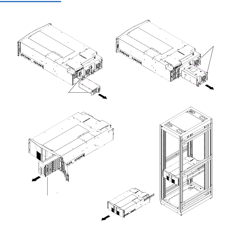
Appendix D Repacking the Scalar 50 Library
Removing the Library from the Rack
Quantum Scalar 50 User’s Guide 219
Figure 124 Removing the
Scalar 50 Library
Power supplies
Tape drives
Right magazine
Appendix D Repacking the Scalar 50 Library
Installing the Internal Shipping Restraints
Quantum Scalar 50 User’s Guide 220
Installing the Internal Shipping Restraints
To ensure that the internal robotics within the library is not damaged,
you must install the internal shipping restraints on the robotics.
Caution: Failure to install the shipping restraints on the robotics
may void your warranty.
To install the internal shipping restraints:
1Place the library on a flat surface approximately waist high:
2Insert the emergency access tool included with the accessory kit into
the release holes and trip the magazine door release for both the right
and left magazine doors (see figure 125).
The magazine access doors open.
Note: If the bottom FlexLink cover has been removed, replace it
before shipping the library back to Quantum.
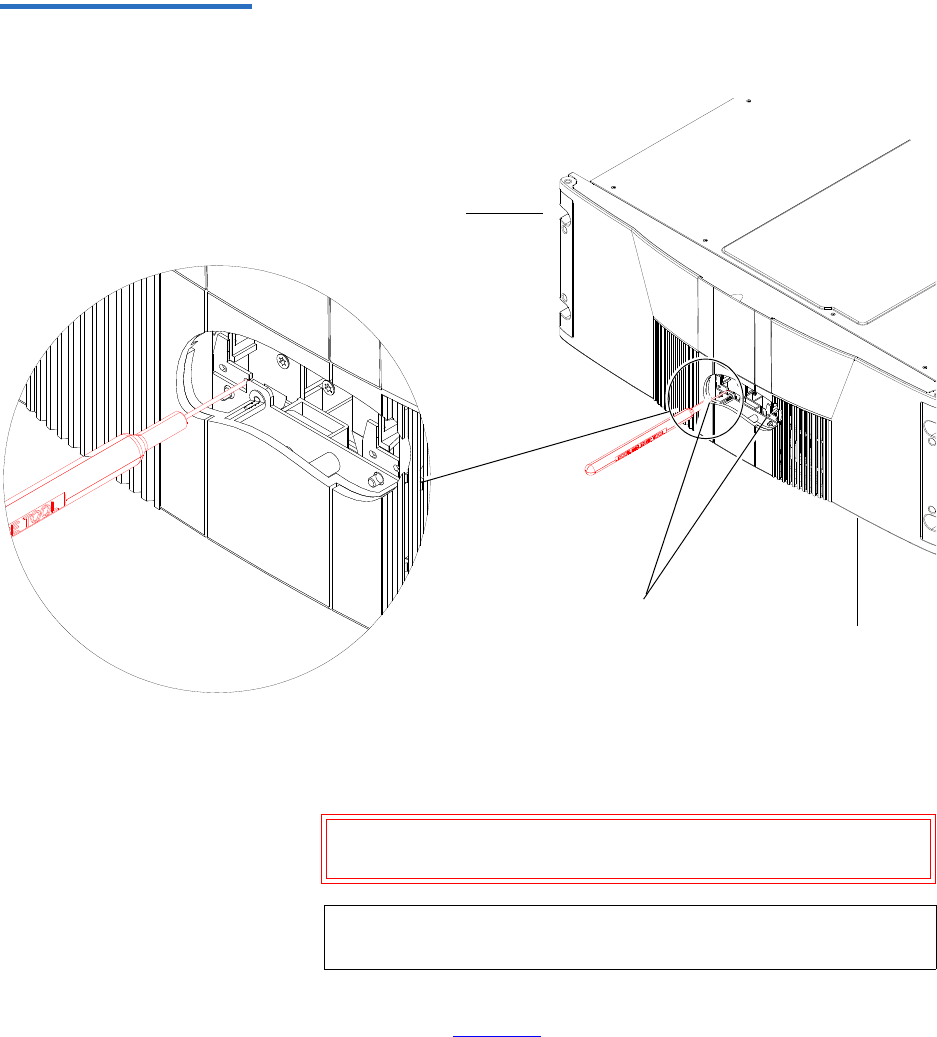
Appendix D Repacking the Scalar 50 Library
Installing the Internal Shipping Restraints
Quantum Scalar 50 User’s Guide 221
Figure 125 Opening the Right
and Left Magazine Access
Doors
Right magazine door
Door releases
Left magazine door
3If the library is not operational and the Park for Shipping command
was not executed, grasp the robotics and gently move it to the front of
the library.
Caution: Take standard ESD precautions when working within
the library chassis.
4Install the robotic restraint over the robotics and secure with two
thumb screws figure 126.
Note: If there are any cartridges in the fixed bins, you can
remove them now.
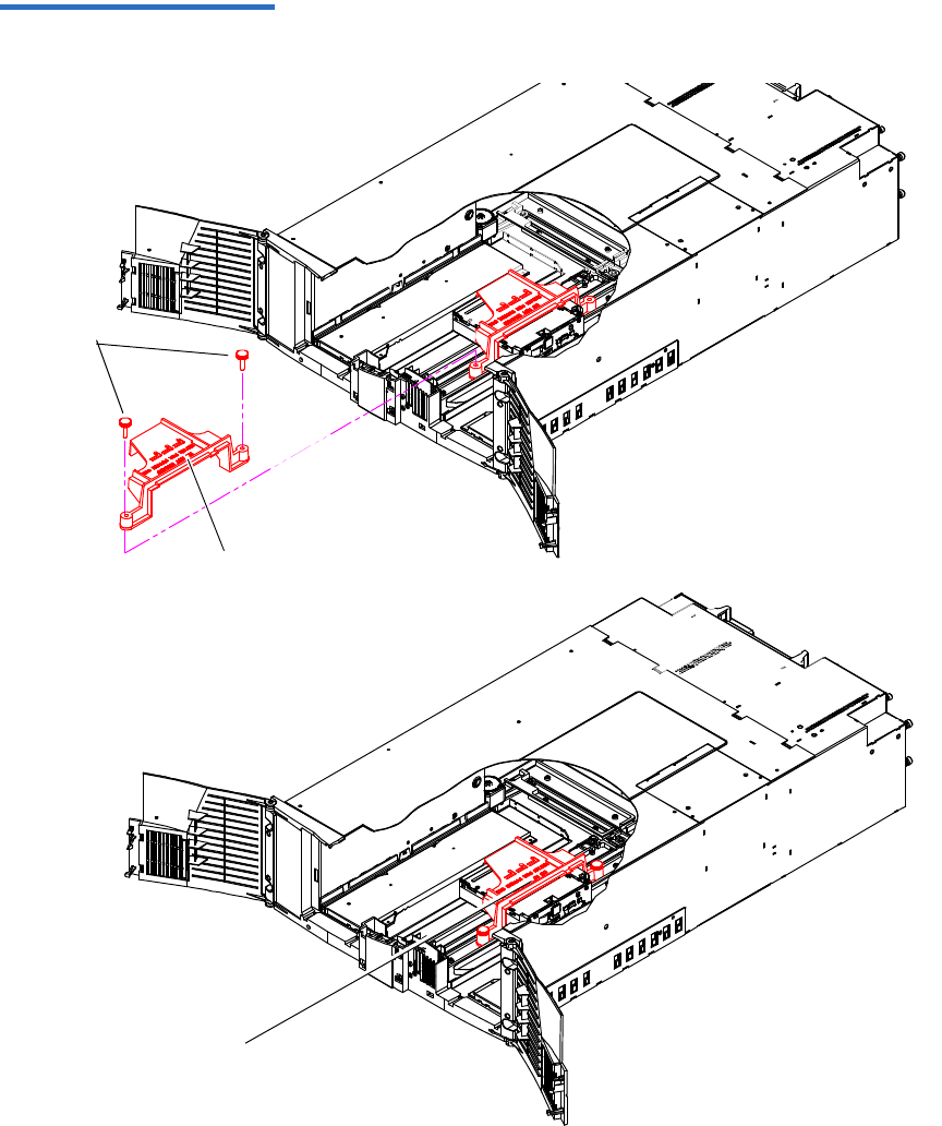
Appendix D Repacking the Scalar 50 Library
Installing the Internal Shipping Restraints
Quantum Scalar 50 User’s Guide 222
Figure 126 Installing
the Hand Restraint
Hand restraint
Thumb
screws
Hand restraint
installed
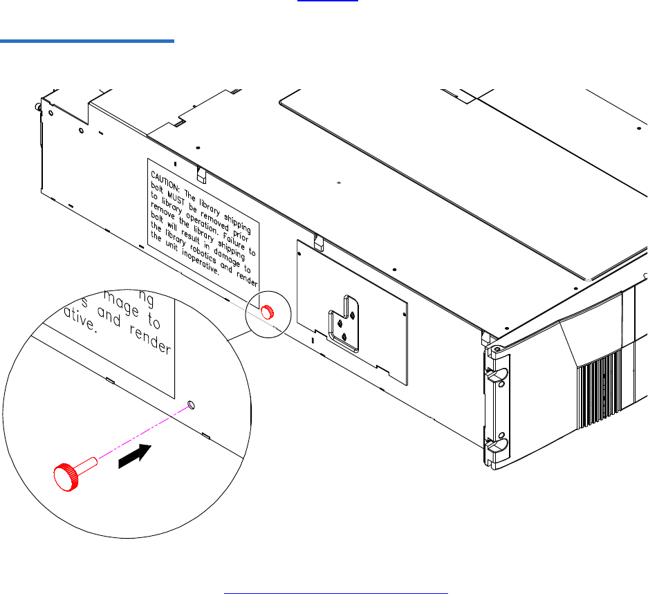
Appendix D Repacking the Scalar 50 Library
Installing the Internal Shipping Restraints
Quantum Scalar 50 User’s Guide 223
5Replace the tape magazines and close the front doors.
6Install the thumb screw restraint on the left-hand side of the library
chassis (see figure 127).
Figure 127 Installing the
Restraining Bolt
7Install the tape drives, and power supplies previously removed in
Removing the Library from the Rack.
8Install the tape cartridge magazines.
Appendix D Repacking the Scalar 50 Library
Packing the Library for Shipment
Quantum Scalar 50 User’s Guide 224
Packing the Library for Shipment
1Carefully place the library into the antistatic bag.
2Package the library into the shipping carton as shown in figure 128.
Ensure that the library chassis is placed in an antistatic bag before
placing the library in the shipping carton
Warning: At least two people are required to move the library
chassis.
Caution: Lift the library chassis at the sides. Avoid putting the
weight of the library chassis on the front bezel.
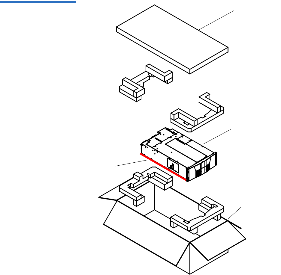
Appendix D Repacking the Scalar 50 Library
Packing the Library for Shipment
Quantum Scalar 50 User’s Guide 225
Figure 128 Preparing the
Library for Shipping
Shipping carton
Front bezel
Library chassis
Accessories kit
Lift point

Quantum Scalar 50 User’s Guide 226
Appendix E
EFirmware Upgrade Instructions
for Stacked Libraries
If Scalar 50 libraries are in a multiple library stack, the library firmware
must be uploaded individually to each cabinet. If you attempt to upload
library firmware to only the Master library in the stack, the slave libraries
may not receive the firmware update properly.
Uploading library firmware to a multiple library stack consists of the
following steps:
•Changing the Library Stack Role
•Uploading Library Firmware
•Returning the Library Stack Role
Note: If your libraries are partitioned, the partitioning information
will be lost after the firmware upgrade. You must recreate the
partitions after the firmware upgrade is complete.
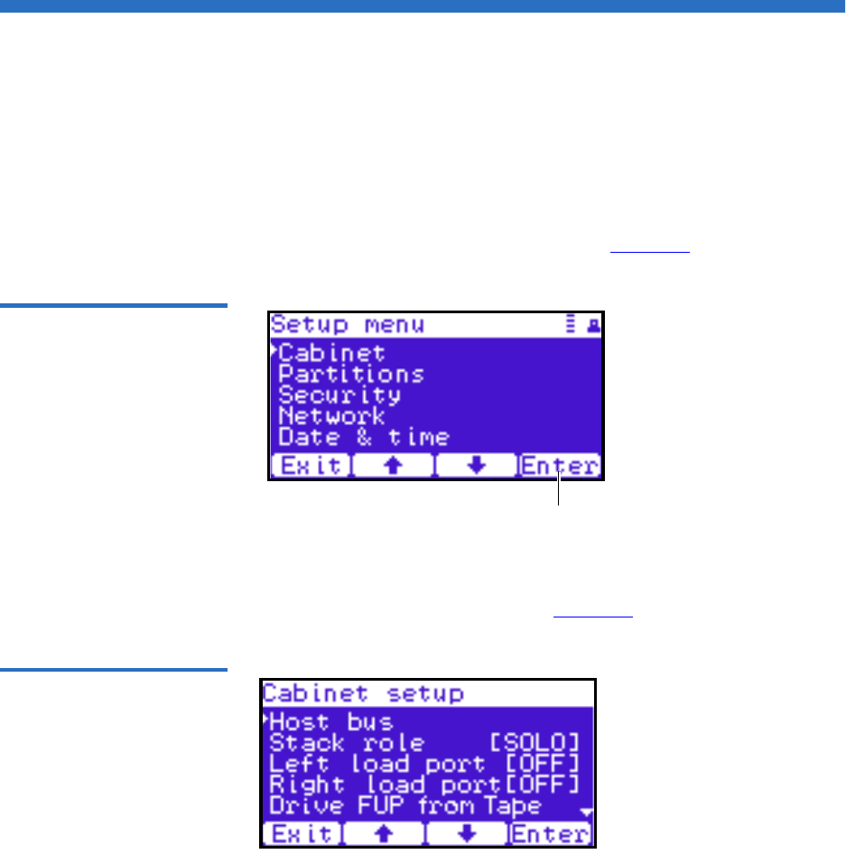
Appendix E Firmware Upgrade Instructions for Stacked Libraries
Changing the Library Stack Role
Quantum Scalar 50 User’s Guide 227
Changing the Library Stack Role
The library must be in Stand alone mode prior to receiving the library
firmware update.
To change the library stack role:
1From the Operator Control Panel (OCP), press Setup from the Home
screen.
The OCP displays the Setup screen (see figure 129):
Figure 129 Setup Screen
Enter
2From the Setup screen, use the up and down arrows to select Cabinet
and press Enter.
The Cabinet screen displays (see figure 130):
Figure 130 Cabinet Screen
3Use the up and down arrows to select Stack role and press Enter.

Appendix E Firmware Upgrade Instructions for Stacked Libraries
Uploading Library Firmware
Quantum Scalar 50 User’s Guide 228
The Stack role screen displays.
4Use the up and down arrows to select Stand alone and press Enter.
The system prompts you with a confirmation screen asking Change to
Standalone and reboot this system?
5Press Yes.
The library shuts down. Continue with Uploading Library Firmware.
Uploading Library Firmware
After the library stack role is set to Stand alone, you can upload library
firmware to the cabinet.
To upload library firmware:
1Connect an Ethernet cable to the left-hand Ethernet port on the
library SCB and to a network host on the same subnet as the library
(see figure 131).
Note: Make note of the original stack role. You must return the
library to its original stack role after the library firmware
has been updated.
Note: If this was the Master library, there will already be an
Ethernet cable connected to the library SCB.
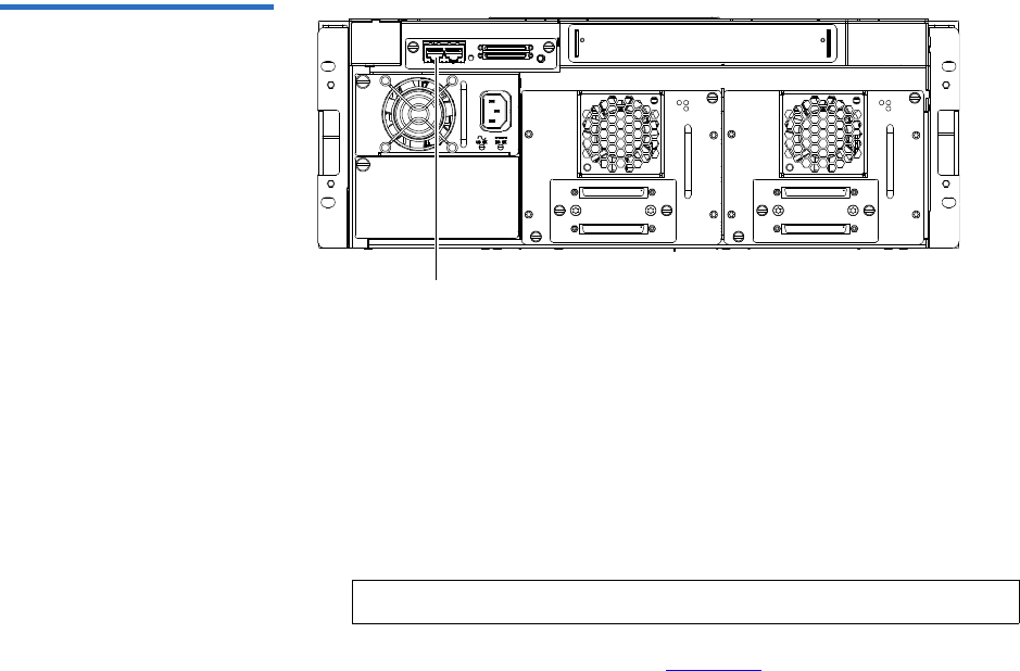
Appendix E Firmware Upgrade Instructions for Stacked Libraries
Uploading Library Firmware
Quantum Scalar 50 User’s Guide 229
Figure 131 Connecting to the
Library SCB
Ethernet port
2Use the OCP to determine the IP address for the library. The Network
information is available from the Info menu.
3On the host computer, open the internet browser software.
4In the Address field, type http://IPaddress/ where IP address is the IP
address for the library.
5Enter the username and password and click OK.
The Overview page displays (see figure 132).
Note: The default username and password is admin.
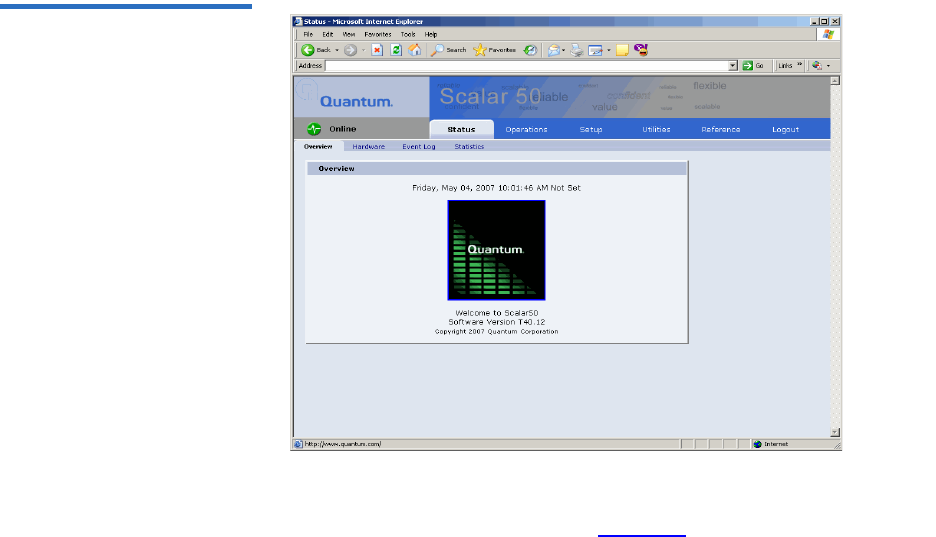
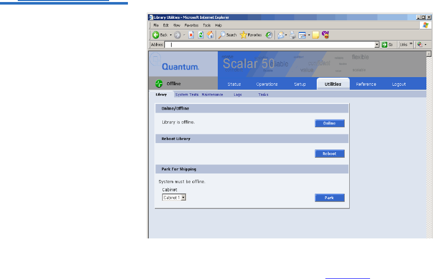
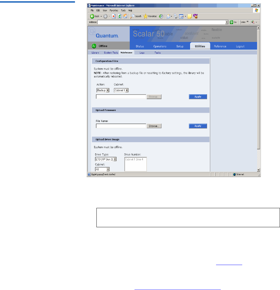
Appendix E Firmware Upgrade Instructions for Stacked Libraries
Uploading Library Firmware
Quantum Scalar 50 User’s Guide 232
Figure 134 Maintenance Page
8To upload the library firmware, enter a path and filename where the
file exists, or click Browse.
9 Click Apply to upload the file.
The firmware image uploads to the library.
10 Reboot the library from the Utilities page (see figure 133).
The library reboots. Repeat the firmware upgrade procedure for
every library in the stack. When all libraries have been updated,
continue with Returning the Library Stack Role.
Note: Be sure to use the same library firmware for all libraries in
the stack.

Appendix E Firmware Upgrade Instructions for Stacked Libraries
Returning the Library Stack Role
Quantum Scalar 50 User’s Guide 233
Returning the Library Stack Role
After the library firmware has been updated on all of the libraries and the
libraries have rebooted, you must return each library to its original
library stack role.
To return the library stack role:
1From the OCP, press Setup from the Home screen.
The OCP displays the Setup screen (see figure 135):
Figure 135 Setup Screen
Enter
2From the Setup screen, use the up and down arrows to select Cabinet
and press Enter.
The Cabinet screen displays (see figure 136):
Figure 136 Cabinet Screen
3Use the up and down arrows to select Stack role and press Enter.
The Stack role screen displays.

Appendix E Firmware Upgrade Instructions for Stacked Libraries
Returning the Library Stack Role
Quantum Scalar 50 User’s Guide 234
4Use the up and down arrows to select the appropriate stack role
(Master/Slave) for this library and press Enter.
The system prompts you with one of the following confirmation
screens asking:
•Change to Master and reboot this system?
•Change to Slave and reboot this system?
5Press Yes.
The library shuts down.
When all the libraries in the stack have been returned to their original
stack role, power on all of the libraries and return to normal operation.
Note: If stack role is changed to Master, there will be an
additional Attention screen that suggests the users to
remove the old master if the current stand alone cabinet is
added to an existing stack. Press Ok after confirmation.
Note: If the stack role is changed to Slave, the Ethernet cable can
be disconnected from cabinet's system controller board.

Quantum Scalar 50 User’s Guide 235
Appendix F
FRegulatory Statements
This appendix provides the regulatory statements for the Quantum
Scalar 50 libraries, in the following languages:
• English (page 208)
• Deutsch (seite page 238)
• Español (página page 240)
• Français (page page 243)
• Italiano (pagina page 245)
•Svenska (sidan page 247)
• (Simplified Chinese) (page 249)
• (Traditional Chinese) (page 251)
• (Japanese) (page 253)
• (Korean) (page 255)
English
FCC Statement This equipment has been tested and found to comply with the limits for a
Class A digital device, pursuant to Part 15 of the FCC Rules. These limits
are designed to provide reasonable protection against harmful
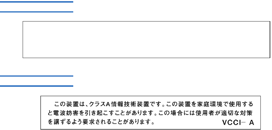
Appendix F Regulatory Statements
Quantum Scalar 50 User’s Guide 236
interference when the equipment is operated in a commercial
environment. This equipment generates, uses, and can radiate radio
frequency energy and, if not installed and used in accordance with the
instruction manual, may cause harmful interference to radio
communications.
Any changes or modifications made to this equipment may void the
user's authority to operate this equipment.
Operation of this equipment in a residential area may cause interference
in which case the user at his own expense will be required to take
whatever measures may be required to correct the interference.
This device complies with Part 15 of the FCC Rules. Operation is subject
to the following conditions:
1This device may not cause harmful interference, and
2This device must accept any interference received, including
interference that may cause undesired operation.
Taiwan (BSMI) Statement
!" #$%&'()*+,-.
Japan (VCCI) Statement
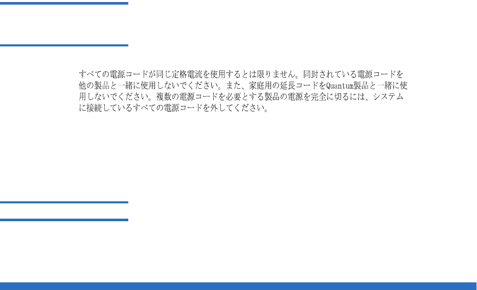
Appendix F Regulatory Statements
Quantum Scalar 50 User’s Guide 237
DEN-AN Notice (Japan
Industry Canada Digital
Apparatus)
Reference: Interference-Causing Equipment Standard, ICES-003, Issue 2
This Class A digital apparatus meets all requirements of the Canadian
Interference-Causing Equipment Regulations.
CISPR-22 Warning! This is a Class A product. In a domestic environment this product may
cause radio interference in which case the user may be required to take
adequate measures.
Notice for USA and CANADA Only
If shipped to USA, use the UL LISTED power cord specified below for
100-120 V operation. If shipped to Canada, use the CSA CERTIFIED
power cord specified below for 100-120V operation.
Plug Cap Parallel blade with ground pin (NEMA 5-15P
configuration)
Cord Type: SJT, three 16 AWG (1.5 mm2) or
18 AWG (1.0 mm2) wires
Length Maximum 15 feet (4.5m)
Rating Minimum 10 A, 125 V

Appendix F Regulatory Statements
Quantum Scalar 50 User’s Guide 238
Laser Statement 6CAUTION: With all panels and enclosures in place, this product is rated
as a Class I laser product.
CAUTION: Use of controls or adjustments or performance of procedures
other than those specified herein may result in hazardous exposure.
Library Battery Statement CAUTION: This product contains a Lithium battery. Lithium may be
considered a hazardous material. Dispose of this battery in accordance
with local, state, and federal laws. The Lithium batteries included in this
product are:
• Panasonic BR1225
• IC Battery ST Micro M41T81
Battery Contained in Product: 6
“Perchlorate Material – special handling may apply, See
www.dtsc.ca.gov/hazardouswaste/perchlorate.”
• The foregoing notice is provided in accordance with California
Code of Regulations Title 22, Division 4.5 Chapter 33, Best
Management Practices for Perchlorate Materials. This product/
part includes a lithium battery which contains a perchlorate
substance.
Deutsch
Regelungen der FCC Nach Tests wurde festgelegt, dass dieses Gerät den digitalen Geräten der
Klasse A entspricht und den Vorschriften in Abschnitt 15 der Regelungen
der FCC unterliegt. Durch diese Vorschriften wird ein angemessener
Schutz vor schädlichen Strahlungen gewährleistet, wenn dieses Gerät in
einer kommerziellen Umgebung betrieben wird. Von den Geräten wird
Hochfrequenzenergie erzeugt, genutzt und abgestrahlt, die bei einer im
Widerspruch zu diesem Handbuch stehenden Installation oder Nutzung
Funkstörungen erzeugen kann.

Appendix F Regulatory Statements
Quantum Scalar 50 User’s Guide 239
Änderungen und Modifikationen an diesem Gerät können zum
Erlöschen der Betriebserlaubnis für dieses Gerät führen.
Der Betrieb dieses Geräts in Wohngegenden kann zu Empfangsstörungen
führen, die der Verursacher auf eigene Kosten beheben muss.
Dieses Gerät erfüllt die Vorschriften in Abschnitt 15 der Regelungen der
FCC. Der Betrieb unterliegt den folgenden Bedingungen:
1Das Gerät darf keine schädlichen Störungen hervorrufen und
2Das Gerät muss alle eingehenden Störungen aufnehmen,
einschließlich Störungen, die einen unerwünschten Betrieb
verursachen können.
Regelungen für Taiwan
!" #$%&'()*+,-.
Industry Canada (Digital-
Apparate) Referenz: Norm für störungsverursachende Geräte, ICES-003, Ausgabe 2
Dieses Digitalgerät der Klasse A erfüllt alle Anforderungen der
kanadischen Vorschriften bezüglich störungsverursachender Geräte
(Canadian Interference-Causing Equipment Regulations).
CISPR-22 Warnung! Dies ist ein Produkt der Klasse A. Dieses Produkt kann in
Wohngegenden Funkstörungen verursachen, die vom Verursacher durch
angemessene Maßnahmen behoben werden müssen.
Hinweis nur für USA und
KANADA Wenn dieses Produkt in die USA geliefert wird, muss das nachstehend
für einen 100-120-Volt-Betrieb spezifizierte und von UL zugelassene
Netzkabel verwendet werden. Wenn dieses Produkt nach Kanada
geliefert wird, muss das nachstehend für einen 100-120-Volt-Betrieb
spezifizierte und von CSA zugelassene Netzkabel verwendet werden.

Appendix F Regulatory Statements
Quantum Scalar 50 User’s Guide 240
SteckerausführungParallele Steckzungen mit Erdungsstift
(NEMA 5-15P-Konfiguration)
Kabel Typ: SJT, drei 16 AWG (1,5 mm2)- oder
18 AWG (1,0 mm2)-Leiter
Länge Max. 15 Fuß (4,5 m)
Nennleistung Min. 10 A, 125 V
Laser-Erklärung VORSICHT: Wenn alle Abdeckungen und Gehäuseteile korrekt
angebracht sind, handelt es um ein Produkt der Laserklasse 1. Der
Strichcodescanner in diesem Produkt ist jedoch ein Laser Klasse II.
Vermeiden Sie die Aussetzung an die von dem Strichcodescanner
ausgehenden Strahlen. Blicken Sie nicht direkt in den Strahl.
VORSICHT: Die unsachgemäße Verwendung von Bedienelementen
oder Einstellungen bzw. die Ausführung von Arbeitsschritten, die nicht
in der mit dem Gerät gelieferten Dokumentation beschrieben sind,
können dazu führen, dass gesundheitsschädigende Strahlungen
freigesetzt werden.
Hinweis zur
Bibliotheksbatterie VORSICHT: Dieses Produkt enthält eine Lithium-Batterie. Das
nichtflüchtige RAM, Dallas Semiconductor DS1743-100, enthält eine
Lithium-Batterie. Lithium ist eventuell als gefährliches Material zu
betrachten. Die Entsorgung dieser Batterie muss unter Einhaltung aller
lokalen, regionalen und bundesweiten Gesetze und Vorschriften
erfolgen.
Español
Declaración FCC Este equipo ha sido sometido a prueba y ha demostrado cumplir con los
límites de un dispositivo digital de Clase A, conforme a la Parte 15 de las
Normas FCC. Estos límites están diseñados para proporcionar una
protección razonable contra las interferencias perjudiciales cuando el

Appendix F Regulatory Statements
Quantum Scalar 50 User’s Guide 241
equipo funciona en un entorno comercial. Este equipo genera, usa y
puede emitir energía de radiofrecuencia y, si no se instala ni se usa de
acuerdo con el manual de instrucciones, puede provocar interferencias
perjudiciales para las comunicaciones de radio.
Cualesquiera cambios o modificaciones realizados a este equipo pueden
anular la autoridad del usuario para utilizar este equipo.
El uso de este equipo en un área residencial puede provocar
interferencias, en cuyo caso será el usuario quien tenga que correr con los
gastos de las medidas que puedan ser necesarias para corregir las
interferencias.
Este dispositivo cumple con la Parte 15 de las Normas FCC. El
funcionamiento está sujeto a las siguientes condiciones:
1Este dispositivo no debe causar interferencias perjudiciales, y
2Este dispositivo debe aceptar cualquier interferencia que reciba,
incluidas aquéllas que puedan provocar un funcionamiento no
deseado.
Declaración para Taiwán
!" #$%&'()*+,-.
Industria de Canadá
(Aparato digital) Referencia: Interference-Causing Equipment Standard (Estándar para equipos
que causan interferencia), ICES-003, Issue 2 (Tema 2)
Este aparato digital de Clase A cumple todos los requisitos de la
normativa canadiense sobre equipos que causan interferencia.
Advertencia CISPR-22 Éste es un producto de Clase A. En un entorno doméstico, este producto
puede causar interferencias de radio, en cuyo caso puede ser necesario
que el usuario tome medidas adecuadas.

Appendix F Regulatory Statements
Quantum Scalar 50 User’s Guide 242
Aviso sólo para EE.UU. y
CANADÁ Si el producto se ha fabricado para EE.UU., utilice el cable de
alimentación UL LISTED que se especifica más adelante para el
funcionamiento a 100-120 V. Si el producto se ha fabricado para Canadá,
utilice el cable de alimentación CSA CERTIFIED que se especifica más
adelante para el funcionamiento a 100-120 V.
Enchufe Cuchilla paralela con patilla de conexión a tierra
(configuración NEMA 5-15P)
Cable Tipo SJT, tres cables 16 AWG (1,5 mm2) ó
18 AWG (1,0 mm2)
Longitud Máxima de 15 pies (4,5m)
Clasificación Máximo 10 A, 125 V
Declaración sobre láser PRECAUCIÓN: Con todos los paneles y cubiertas en su sitio, este
producto se clasifica como un producto láser de Clase I. Sin embargo, el
lector de código de barras que hay en el interior de este producto es un
láser de Clase II. Evite la exposición a la luz del láser que emite el lector
de código de barras. No mire fijamente el rayo.
PRECAUCIÓN: El uso de controles o ajustes o la realización de
procedimientos distintos de los que se especifican en este manual pueden
provocar una exposición peligrosa.
Declaración sobre la
batería de la biblioteca PRECAUCIÓN: Este producto contiene una batería de litio. La memoria
RAM no volátil, Dallas Semiconductor DS1743-100, contiene una batería
de litio. El litio puede ser considerado un material peligroso. Deseche la
batería conforme a la norma vigente de aplicación local, del estado y
federal.

Appendix F Regulatory Statements
Quantum Scalar 50 User’s Guide 243
Français
Déclaration de la FCC Cet équipement a été testé et s'est révélé conforme aux limites d'un
appareil numérique de Classe A, conformément à l'alinéa 15 de la
réglementation de la FCC. Ces limites sont conçues pour fournir une
protection adéquate contre les perturbations nuisibles lorsque
l'équipement fonctionne dans un environnement commercial. Cet
équipement génère, utilise et peut émettre une énergie à fréquence radio
et risque, s'il n'est pas installé et utilisé conformément au manuel
d'instruction, de créer des perturbations nuisibles aux services de
radiocommunication.
Tout changement ou modification apporté à cet équipement risque
d'annuler le droit d'utiliser l'équipement.
L'utilisation de cet équipement dans une zone résidentielle risque de
créer des perturbations auxquelles l'utilisateur devra remédier à ses
propres frais.
Cet appareil est conforme à l'alinéa 15 de la réglementation de la FCC. Le
fonctionnement de cet équipement est soumis aux conditions suivantes :
1Cet appareil ne peut générer de perturbations nuisibles et
2Cet appareil doit accepter les perturbations reçues, notamment les
perturbations qui risquent de générer un fonctionnement non
souhaité.
Réglementation de Taïwan
!" #$%&'()*+,-.

Appendix F Regulatory Statements
Quantum Scalar 50 User’s Guide 244
Industrie Canada
(Appareil numérique) Référence : Norme sur le matériel brouilleur, NMB-003, numéro 2
Cet appareil numérique de Classe A satisfait à toutes les exigences des
réglementations canadiennes sur le matériel brouilleur.
Avertissement CISPR-22 ! Ceci est un produit de Classe A. Dans un environnement résidentiel, ce
produit risque de générer des perturbations radio auxquelles l'utilisateur
doit peut-être remédier.
Avis pour les États-Unis et
le Canada uniquement En cas d'envoi aux États-Unis, utilisez le câble d'alimentation CLASSÉ UL
spécifié ci-dessous pour un fonctionnement à 100-120 V. En cas d'envoi
au Canada, utilisez le câble d'alimentation CERTIFIÉ CSA spécifié ci-
dessous pour un fonctionnement à 100-120 V.
Fiche Broche parallèle avec broche de mise à la terre
(configuration NEMA 5-15P)
Cordon Type : SJT, trois fils 16 AWG (1,5 mm2) ou
18 AWG (1,0 mm2)
Longueur 15 pieds (4,5 m) au maximum
Courant nominal10 A au minimum, 125 V
Réglementation relative
au laser ATTENTION : Avec tous les panneaux et enceintes en place, ce produit
est classé comme un produit laser de Classe I. Le lecteur de codes-barres à
l'intérieur de ce produit est, cependant, un laser de Classe II. Évitez toute
exposition à la lumière laser émise par le lecteur de codes-barres. Ne fixez
pas le faisceau des yeux.
ATTENTION : L'utilisation de commandes ou de réglages ou l'exécution
de procédures autres que celles spécifiées ici peuvent entraîner une
exposition dangereuse.
Réglementation relative à
la pile de la bibliothèque ATTENTION : Ce produit comporte une batterie au lithium. La mémoire
RAM non-volatile, Dallas Semiconductor DS1743-100, comporte une pile
au lithium. Le lithium peut être considéré comme un matériau

Appendix F Regulatory Statements
Quantum Scalar 50 User’s Guide 245
dangereux. Mettez cette batterie au rebut conformément aux lois locales,
nationales et fédérales.
Italiano
Dichiarazione FCC Questa apparecchiatura è stata provata e trovata conforme ai limiti per i
dispositivi digitali di Classe A, relativi alla Parte 15 delle norme FCC.
Questi limiti sono concepiti per garantire un livello ragionevole di
protezione da interferenze dannose quando l'apparecchiatura viene
azionata in un ambiente commerciale. Questa apparecchiatura genera,
utilizza e può irradiare energia a radiofrequenza e, se non installata e
utilizzata secondo il manuale di istruzioni, potrebbe causare interferenze
dannose alle comunicazioni radio.
Eventuali cambiamenti o modifiche apportati a questa apparecchiatura
potrebbero invalidare il diritto dell'utente ad utilizzare questa
apparecchiatura.
Il funzionamento dell'apparecchiatura in una zona residenziale potrebbe
causare interferenze, nel qual caso l'utente dovrà a proprie spese
prendere i dovuti provvedimenti per eliminare le interferenze.
Questo dispositivo è conforme alla Parte 15 delle norme FCC. Il
funzionamento è soggetto alle seguenti condizioni:
1Questo dispositivo non può causare interferenze dannose e
2Questo dispositivo deve accettare eventuali interferenze ricevute,
incluse le interferenze causate da funzionamento indesiderato.
Dichiarazione per Taiwan
!" #$%&'()*+,-.

Appendix F Regulatory Statements
Quantum Scalar 50 User’s Guide 246
Industry Canada (apparati
digitali) Riferimento: Interference-Causing Equipment Standard, ICES-003, 2.
edizione
Questo dispositivo digitale di Classe A è conforme a tutti i requisiti dei
regolamenti canadesi per apparecchiature che causano interferenze.
Avvertenza CISPR-22! Questo è un prodotto di Classe A. In un ambiente domestico questo
prodotto potrebbe causare interferenze radio; in tal caso l'utente dovrà
adottare tutti i dovuti provvedimenti.
Avviso esclusivamente
per Stati Uniti e Canada Se il prodotto viene spedito negli Stati Uniti, utilizzare il cavo di
alimentazione elencato UL, specificato di seguito per il funzionamento a
100-120 V. Se il prodotto viene spedito in Canada, utilizzare il cavo di
alimentazione certificato CSA, specificato di seguito per il funzionamento
a 100-120 V.
Cappuccio della spinaLama parallela con perno di terra (configurazione
NEMA 5-15P)
Cavo: Tipo: SJT, tre fili da 16 AWG (1,5 mm2) o
18 AWG (1,0 mm2)
Lunghezza Massima di 15 piedi (4,5 m)
Portata Minima di 10 A, 125 V
Dichiarazione sui
dispositivi laser ATTENZIONE: Con tutti i pannelli e le custodie in posizione, questo
prodotto è classificato come prodotto laser di Classe I. Lo scanner per
codici a barre all'interno del prodotto è invece un dispositivo laser di
Classe II. Evitare l'esposizione ai raggi laser emessi dallo scanner per
codici a barre. Non guardare fisso nel fascio di luce.
ATTENZIONE: L'utilizzo di comandi, regolazioni o procedure diversi da
quelli specificati in questa sede potrebbe causare livelli di esposizione
pericolosi.

Appendix F Regulatory Statements
Quantum Scalar 50 User’s Guide 247
Dichiarazione sulla
batteria della libreria ATTENZIONE: Questo prodotto contiene una batteria al litio. La RAM
non volatile, di tipo Dallas Semiconductor DS1743-100, contiene una
batteria al litio. Il litio potrebbe essere considerato un materiale
pericoloso. Smaltire la batteria secondo quanto previsto dalle leggi locali,
regionali e nazionali.
Svenska
FCC-meddelande Utrustningen har testats och befunnits uppfylla gränserna för en klass A
digital enhet i enlighet med del 15 i FCC-reglerna. Gränserna är
utformade att tillhandahålla rimligt skydd mot störningar när
utrustningen används i en kommersiell miljö. Utrustningen alstrar,
använder och kan utstråla radiofrekvent energi och kan, om den ej
installeras och används i enlighet med instruktionshandboken, orsaka
störningar i radiokommunikation.
Eventuella ändringar eller modifikationer av utrustningen kan
ogiltigförklara användarens rätt att använda utrustningen.
Användning av utrustningen i bostadsområden kan orsaka störningar
och i sådana fall måste användaren bekosta de åtgärder som krävs för att
åtgärda störningarna.
Enheten uppfyller del 15 i FCC-reglerna. Användningen underkastas
följande villkor:
1Enheten får inte orsaka störningar och
2enheten måste tåla mottagna störningar, inklusive störningar som
kan orsaka oönskad funktion.

Appendix F Regulatory Statements
Quantum Scalar 50 User’s Guide 248
Meddelande för Taiwan
!" #$%&'()*+,-.
Kanada (digital
utrustning) Hänvisning: Standard för störningsalstrande utrustning, ICES-003, utgåva 2
Denna klass A för digital utrustning uppfyller alla krav i de kanadensiska
föreskrifterna för störningsalstrande utrustning.
CISPR-22 Varning! Detta är en klass A produkt. I en hemmiljö kan denna produkt orsaka
radiostörningar, i vilket fall det kan krävas att användaren vidtar
lämpliga åtgärder.
Meddelande för USA och
KANADA enbart Om utrustningen levereras i USA, använd den UL-listade nätsladden
som specificeras nedan för användning med 100-120 V. Om utrustningen
levereras i Kanada, använd den CSA-certifierade nätsladden som
specificeras nedan för användning med 100-120 V.
Kontaktkåpa Parallellt blad med jordstift
(NEMA 5-15P-konfiguration)
Sladd Typ: SJT, tre 1,5 mm2 (16 AWG) eller
1,0 mm2 (18 AWG) ledare
Längd Maximalt 15 fot (4,5 m)
Märkvärde Minimalt 10 A, 125 V
Lasermeddelande FÖRSIKTIGHET: Med alla paneler och luckor på plats klassificeras
denna produkt som en laserprodukt klass 1. Streckkodsläsaren inuti
produkten är klassificerad som en laserprodukt klass II. Undvik kontakt
med streckkodsläsarens laserstråle. Titta inte in i strålen.
Appendix F Regulatory Statements
Quantum Scalar 50 User’s Guide 249
FÖRSIKTIGHET: Användning av kontroller, justeringar eller utförande
av rutiner andra än de som anges i detta dokument kan leda till farlig
exponering för strålning.
Meddelande om
biblioteksbatteri FÖRSIKTIGHET: Produkten innehåller ett litiumbatteri. Det icke-
flyktiga RAM-minnet, Dallas halvledare DS1743-100, innehåller ett
litiumbatteri. Litium anses som riskavfall. Kasta batteriet i enlighet med
lokala och nationella lagar.
Simplified Chinese
FCC
1
2
!" #$%&'()*+,-.
Appendix F Regulatory Statements
Quantum Scalar 50 User’s Guide 250
CISPR-22
mp

Appendix F Regulatory Statements
Quantum Scalar 50 User’s Guide 251
Traditional Chinese
FCC
1
2
!" #$%&'()*+,-.
Appendix F Regulatory Statements
Quantum Scalar 50 User’s Guide 252
CISPR-22
Appendix F Regulatory Statements
Quantum Scalar 50 User’s Guide 253
Japanese
FCC
1
2
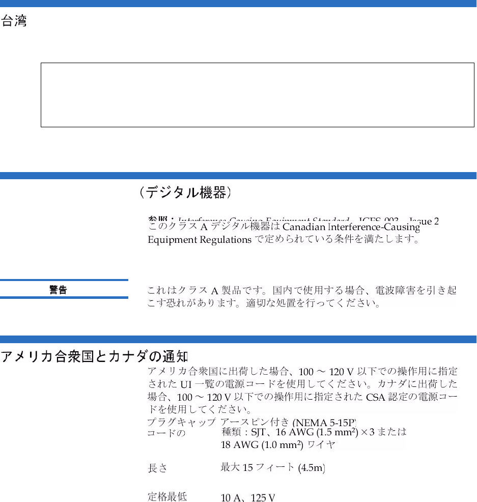
!" #$%&'()*+,-.
Appendix F Regulatory Statements
Quantum Scalar 50 User’s Guide 254
Industry Canada
CISPR-22
Appendix F Regulatory Statements
Quantum Scalar 50 User’s Guide 255
Korean
FCC
Appendix F Regulatory Statements
Quantum Scalar 50 User’s Guide 256
1
2
!" #$%&'()*+,-.
CISPR-22
Appendix F Regulatory Statements
Quantum Scalar 50 User’s Guide 257
Class 1
Disposal of Electrical and Electronic Equipment
This symbol on the product or on its packaging
indicates that this product should not be disposed
of with your other waste. Instead, it should be
handed over to a designated collection point for
the recycling of electrical and electronic
equipment. The separate collection and recycling
of your waste equipment at the time of disposal
will help to conserve natural resources and ensure
that it is recycled in a manner that protects human health and the
environment. For more information about where you can drop off
your waste equipment for recycling, please visit our website at:
http://qcare.quantum.com or contact your local government
authority, your household waste disposal service or the business
from which you purchased the product.
Appendix F Regulatory Statements
Quantum Scalar 50 User’s Guide 258
Declaration of Conformity

Quantum Scalar 50 User’s Guide 259
Glossary
Bback panel The panel at the back of the library that contains
theconnectors for attaching external cabling to the library.
bar code label The identification label on cartridges.
bar code scanner A laser device that is mounted on the robotic hand and
reads the cartridge bar code labels.
Ccalibration The software measurements and configuration required for
successful operation of the library.
FFibre Channel Fibre Channel interface. This is a interface type used in
native Fibre Channel tape drives.
FCC Class A Standard established by the U.S. Federal Communications
Commission governing electromagnetic emissions.
FSE Field service engineer
GGUI Graphical user interface. The browser based remote management
system use to configure and control the Scalar 50 libraries.
Hhost computer The computer that issues SCSI commands to control the
library hand.

Glossary
Quantum Scalar 50 User’s Guide 260
IISCI iSCSI is an IP-based standard for linking data storage devices
over a network and transferring data by carrying SCSI
commands over IP networks.
MMTBF Mean Time Between Failures
MTTR Mean Time To Repair
NNVRAM Nonvolatile random access memory
Ooff-line Library is offline and not able to communicate with a host.
on-line Ready for communications with a host
OCP Operator control panel.
Ppick The act of removing a cartridge from one location in preparation
for placing it in another location.
place The act of placing a cartridge in a location after it has been picked
from another location.
PROM Programmable read-only memory
RRAM Random access memory
SSCSI Small Computer System Interface. A communications standard
for attaching peripheral equipment to small computers.
Ttape drive The mechanism that reads data from, and writes data to, a
tape.
UUL Underwriters Laboratories

Quantum Scalar 50 User’s Guide 261
Index
A
auto clean 53
B
back panel 12
CPCI card cage 11
power supplies 11
system controller board 11
tape drives 12
backup
configuration files 130
barcode label
labeling LTO cartridges 27
browser, internet 64
BSMI (see Taiwan)
C
cabinet setup
OCP 51
cable, SCSI, length 181
cabling routing for the Scalar 50 19
capacity on demand 13, 102
cartridges
handling 182–183
inspecting for damage 183–185
cleaning cartridges 28
COD 102
component test
OCP 59
configuration files
backup 130
factory 130
factory defaults 130
restore 130
restoring 130
saving 130
configure slots 53
CPCI card cage 11
creating a library partition 105
D
date and time
configuration 99
date and time setup
OCP 56
deleting a library partition 108
DHCP
enable from OCP 56
diagnostics
OCP 57
disaster recovery 123
displayed frames 68
DLT-S4
performance 5
DLTSage secure tape
best practices 122
tape migration 122
DLTSage tape security 113
drive firmware
uploading 131
drive operations
OCP 49

Index
262 Quantum Scalar 50 User’s Guide
pwr on/off 50
reset 50
drives page 83
E
editing a partition 107
emergency
access 213
ESD precautions 23
event log 72
viewing 73
event logs
OCP 43
F
fa log file 133
factory defulats
configuration files 130
failure analysis file 133
Fibre Channel
ocp setup 52
find page 78
barcode 79
find media ID 79
select map 80
find tapel
OCP 47
Firefox 64
frames, displayed 68
front panel 8
G
getting started 18
guardian xxii
H
hardware information
OCP 42
hardware status 71
health test 127
home screen 37
HP LTO-3
performance 6
HP LTO-4
performance 7
I
identification 86
info screen
OCP 40
installing
tape cartridges 21
internet browsers, supported 64
inventory page 82
IP address
set from OCP 56
iSCSI bridge
TC2201 92
J
Japan
class A regulatory statement 236
Java plug-in 64
K
key users 88
create 88
creating 88
removing 89
updating key user password 90
L
library
back panel 12
capacity on demand 102
features 8–??
front panel 8
relocating 187
setup 101
library access
emergency 213
library doors
open 22
library emulation 53
library firmware
uploading 130
library operations
OCP 45
online/offline 46
park for shipping 47
release magazines 46
library partitioning
cabinets 106
configured slots 107

Index
Quantum Scalar 50 User’s Guide 263
creating 105
deleting 108
drives 106
editing 107
emulate P-Series 106
emulate Scalar 50 106
enable autoclean 106
enable barcode swap 106
load ports 106
magazines 106
partition name 106
scsi logical unit (LUN) 106
Library setup
emulation 53
library setup
configure slots 53
load port configuration 60
logs 131
fa log 133
M
magazines
release 46
removing 22
maintenance 129
mixed media 13
move page 80
move tape
OCP 48
Mozilla Suite 64
N
network configuration
fields 95
network information 93
network setup
OCP 55
O
OCP
buttons 38
components 38
home screen 37
info screen 40
operations screen 45
overview 37–38
problems 166
OCP diagnostics screen 57
component tests 59
subsystem tests 58
system-level tests 58
OCP info screen
event logs 43
hardware information 42
overview information 41
statistics information 43
OCP LED status 171
OCP operations screen
drive operations 49
find tape 47
library operations 45
move tape 48
scan inventory 50
OCP setup screen 50
cabinet setup 51
date and time setup 56
network setup 55
partition setup 52
security 54
offline 46
online 46
online/offline
from remote management pages
126
from the OCP 37
open library doors 22
operating problems 168
operations
accessing 77, 104
drives 83
find 78
inventory 82
move page 80
operations screen
OCP 45
overview information
OCP 41
P
park for shipping 47
partition setup
auto clean 53
barcode swap 53
OCP 52
partitions
native Fibre Channel interface
103
requirements 103
setup 102
power supplies 11
power supply LEDs 175
powering off 37
problems
OCP 166

Index
264 Quantum Scalar 50 User’s Guide
operating 168
robotics 166
start-up 165
Q
Quantum LTO-3
performance 6
Quantum LTO-4 HH
performance 7
R
reference
web pages 134
release magazines 46
relocating
library 187
removing magazines 22
reset tape drive 50
restore
configuration files 130
robot
park for shipping 47
robotics problems 166
S
Scalar 50
cable routing 19
scan inventory
OCP 50
SCB
LEDs 171
scb 11
SCSI
cable length 181
SCSI IDs 91
SCSI II specification xx
secure key 113
assign secure key to cartridge
117
backup secure key file 120
create secure key name/secure
key pair 118
delete secure key name 119
enable/disable secure key for
drives 116
protection mode for cartridges
115
select secure key for library 117
upload secure key file 121
secure key migration 122
secure tape
best practices 122
secure users
remove 89
update 90
security
OCP 54
setup
accessing 85
date and time 99
events 95
identification 86
library 101
network 93
partitions 102
SCSI/Fibre 91
setup wizard 108
TC2201 bridge 92
user information 87
setup wizard 108
shipping
park robot 47
SNMP traps 95
start-up
problems 165
statistics 73
statistics information
OCP 43
status 70
event log 72
hardware 71
overview 70
statistics 73
storage care guardian xxii
subsystem tests
OCP 58
system controller board 11
LEDs 171
system -level tests
OCP 58
system tests 128
health tests 127
T
Taiwan
class A regulatory statement 236
tape cartridge
barcode labeling
LTO 27
loading 20
LTO
barcode labeling 27
SDLT
inserting 26

Index
Quantum Scalar 50 User’s Guide 265
write-protect switch 25
tape cartridge migration scenario
123
tape cartridge types
LTO 26
SDLT 24
tape cartridges
handling 182–183
inspecting for damage 183–185
installing 21
key migration 122
tape drive
details 72
reset 50
SCSI IDs 91
tape drive LEDs 176
tape drives 12
FC bridge 92
Fibre Channel OCP setup 52
iSCSI bridge 92
tape magazines
removing 22
tasks 133
TC2201 92
testing the email system 97
tests
system 128
traps
SNMP 95
troubleshooting 164–169
OCP 166
operating 168
robotics 166
start-up 165
turning the library off 37
U
uploading
drive firmware 131
uploading library firmware 130
user information 87
utilities
library 125
logs 131
maintenance 129
tasks 133
V
VCCI (see Japan)
W
Web pages
accessing 67
menu items 64
web pages
using 67
write-protect switch 25
Index
266 Quantum Scalar 50 User’s Guide
