Queclink Wireless Solutions GV500 GPS Locator User Manual GV500 20150918x
Queclink Wireless Solutions Co.,Ltd GPS Locator GV500 20150918x
Contents
- 1. users manual
- 2. User Manual
User Manual
GV5
0
TRA
C
0
0UserManu
a
C
GV500UM00
1
GS
M
a
l
1
M
/G
P
P
RS/
G
Use
TRA
C
V
G
PS
T
rMa
n
C
GV500
U
V
ersion:1.
0
T
rack
e
n
ual
U
M001
0
2
e
rGV
5
5
00
‐0‐
GV5
0
TRA
C
Doc
Ver
s
Dat
e
Sta
t
Doc
Ge
n
Que
eng
i
upo
n
und
e
that
b
y
Q
cust
o
Co
p
Thi
s
Lim
con
t
da
m
or d
e
Co
py
0
0UserManu
a
C
GV500UM00
1
ument Title
s
ion
e
t
us
ument Cont
n
eral Notes
clink offers
i
neering effo
r
n
requireme
n
e
rtaken any i
n
may be in t
h
Q
ueclink wit
h
o
mer’s syste
m
p
yright
s
document
c
m
ited., copyin
g
t
ents thereof,
m
ages. All rig
h
e
sign. All sp
e
py
right © Sh
a
l
1
rol ID
this infor
m
r
ts that use t
h
n
ts specific
a
n
dependent
s
h
e customer’s
h
in a larger
e
m
integrator.
c
ontains pro
p
g
of this doc
u
are forbidd
e
h
ts reserved
e
cification s
u
anghai Que
c
GV500 Us
1.03
2015-09-1
5
Release
TRACGV
5
ation as a
s
h
e products d
e
a
lly provide
d
s
earch for ad
d
possession.
F
e
lectronic s
y
All specific
a
p
rietary tec
h
u
ment and g
i
e
n without e
x
i
n the event
o
u
pplied herei
n
c
link Wirel
e
er manual
5
5
00UM001
s
ervice to i
t
e
signed by
Q
d
to Quecli
n
d
itional rele
v
Furthermore
,
y
stem remain
a
tions suppli
e
h
nical infor
m
i
ving it to ot
h
x
press autho
r
o
f grant of a
n
are subject
t
e
ss Solution
s
t
s customer
s
Q
ueclink. The
n
k by the
c
v
ant informat
i
,
system vali
d
s the respon
s
e
d herein are
s
m
ation whic
h
h
ers and the
u
r
ity. Offende
r
patent or th
e
t
o change wi
t
s
Co., Ltd. 2
0
, to suppor
t
information
c
ustomers.
Q
i
on, includin
g
d
ation of this
s
ibility of th
e
s
ubject to ch
a
is the pro
p
u
sing or com
m
r
s are liable
t
e
registration
t
hout notice
a
0
13
t
applicatio
n
provided is
b
Q
ueclink ha
s
g
any infor
m
s
product des
i
e
customer
o
a
nge.
p
erty of Qu
e
m
munication
o
t
o the paym
e
of a utility
m
a
t any time.
‐1‐
n
and
b
ased
s
not
m
ation
i
gned
o
r the
e
clink
o
f the
e
nt of
m
odel

GV5
0
TRA
C
Con
t
Tabl
Figu
0.
R
1. I
n
2. P
r
3.
G
4.
O
0
0UserManu
a
C
GV500UM00
1
t
ents............
eIndex........
reIndex.......
R
evision histo
r
n
troduction...
1.1.Refere
n
1.2.Terms
a
r
oduct Over
v
2.1.Descrip
2.2.PartsLi
s
2.3.Interfa
c
G
etting Starte
d
3.1.Openin
g
3.2.Closing
3.3.Installi
n
3.4.Installi
n
3.5.Device
S
O
BD II-relate
d
4.1.Comm
u
4.2.OBDII
P
a
l
1
....................
.
....................
.
....................
.
r
y................
.
....................
.
n
ce...............
.
a
ndAbbrevia
t
v
iew.............
.
tion.............
.
s
t.................
.
c
eDefinition
.
d
..................
.
g
theCase...
.
theCase.....
.
n
gaSIMCar
d
n
gtheIntern
a
S
tatusLED...
.
d
features.....
.
u
nicationPro
t
P
arameters..
.
.
....................
.
....................
.
....................
.
....................
.
....................
.
....................
t
ions............
.
....................
.
....................
.
....................
.
....................
.
....................
.
....................
.
....................
d
....................
a
lBackupBa
t
.
....................
.
....................
t
ocols...........
.
....................
Content
s
....................
....................
....................
....................
....................
....................
....................
....................
....................
....................
....................
....................
....................
....................
....................
t
tery.............
....................
....................
....................
....................
s
....................
.
....................
.
....................
.
....................
.
....................
.
....................
.
....................
.
....................
.
....................
.
....................
.
....................
.
....................
.
....................
.
....................
.
....................
.
....................
.
....................
.
....................
.
....................
.
....................
.
.
....................
.
....................
.
....................
.
....................
.
....................
.
....................
.
....................
.
....................
.
....................
.
....................
.
....................
.
....................
.
....................
.
....................
.
....................
.
....................
.
....................
.
....................
.
....................
.
....................
....................
....................
....................
....................
....................
....................
....................
....................
....................
....................
....................
....................
....................
....................
....................
....................
....................
....................
....................
....................
‐2‐
......2
......3
......4
......5
......6
......6
......6
......7
......7
......7
......8
......0
......0
......2
......3
......3
......4
......5
......5
......5

GV5
0
TRA
C
TAB
L
TAB
L
TAB
L
TAB
L
TAB
L
TAB
L
0
0UserManu
a
C
GV500UM00
1
L
E1:GV500
P
L
E2:TERMS
A
L
E3:PARTLI
S
L
E4:DESCRIP
L
E5:DEFINITI
L
E6:COMM
U
a
l
1
P
ROTOCOLRE
A
NDABBREVI
A
S
T..................
.
TIONOFOB
D
ONOFDEVI
C
U
NICATIONP
R
T
FERENCE.......
A
TIONS.........
.
.....................
D
IICONNECTI
O
ESTATUSAN
R
OTOCOLSLIS
T
T
able Ind
e
.
.....................
.
.....................
.
.....................
O
NS..............
DLED............
T...................
e
x
.....................
.....................
.....................
.....................
.....................
.....................
.
.....................
.
.....................
.
.....................
.
.....................
.
.....................
.
.....................
.
.....................
.
.....................
.
.....................
.
.....................
.
.....................
.
.....................
‐3‐
......6
......6
......7
......8
......4
......5

GV5
0
TRA
C
FIG
U
FIG
U
FIG
U
FIG
U
FIG
U
FIG
U
FIG
U
0
0UserManu
a
C
GV500UM00
1
U
RE1:APPEA
R
U
RE2:THEO
B
U
RE3:OPENI
N
U
RE4:CLOSI
N
U
RE5:SIMC
A
U
RE6:BACKU
U
RE7:GV500
a
l
1
R
ANCEOFGV
B
DIICONNEC
T
N
GTHECASE
.
N
GTHECASE.
.
A
RDINSTALLA
T
PBATTERYIN
LEDONTHE
C
500...............
T
ORONTHE
G
.
.....................
.
.....................
T
ION..............
STALLATION.
C
ASE..............
Fi
g
ure I
n
.
.....................
G
V500...........
.
.....................
.
.....................
.
.....................
.
.....................
.
.....................
n
dex
.....................
.....................
.....................
.....................
.....................
.....................
.....................
.
.....................
.
.....................
.
.....................
.
.....................
.
.....................
.
.....................
.
.....................
.
.....................
.
.....................
.
.....................
.
.....................
.
.....................
.
.....................
.
.....................
‐4‐
......7
......8
......1
......2
......3
......3
......4
GV5
0
TRA
C
0.
R
Rev
1.0
0
1.01
1.0
2
0
0UserManu
a
C
GV500UM00
1
R
evision
h
ision D
0
2
0
2
0
2
2
0
a
l
1
h
istor
y
ate
A
0
13-8-16
L
0
14-03-19
C
0
15-09-15
A
A
uthor
L
eo LEI
C
id Xu
A
bside Yu
Descript
Initial
Updated
Updated
Updated
Update
D
Update
L
ion of chan
g
Introduction
the pictures;
4.2 OBD II
P
D
ocument te
m
L
ED status a
n
g
e
information;
P
arameters
m
plate;
n
d device pic
t
t
ures;
‐5‐

GV5
0
TRA
C
1.
I
The
desi
g
on-
b
sen
s
850
/
peri
o
allo
w
ma
n
pro
v
rep
o
sch
e
1.1
.
Tab
l
SN
[1]
1.2
.
Tab
l
Ab
b
PW
R
GN
D
OB
D
SA
E
HS
_
MS
_
SW
_
0
0UserManu
a
C
GV500UM00
1
I
ntroduc
t
GV500 is
a
g
n allows ea
s
b
oard comp
u
s
itivity and
/
900/1800/1
9
o
dically t
r
ac
k
w
s motion
n
agement al
g
v
ided for the
o
rts includin
g
e
duled GPS
p
. Referen
c
l
e 1: GV500
P
Docume
n
GV500 @
T
. Terms a
n
l
e 2: Terms a
n
b
reviation
R
D
D
E
_
CAN
_
CAN
_
CAN
a
l
1
t
ion
a
vehicle tra
c
s
y installatio
n
u
ter and rela
y
fast time
9
00 MHz al
l
k
ed by a ba
c
detection a
n
g
orithms. Sy
s
full feature
d
g
; emergenc
y
p
osition and
m
c
e
P
rotocol Ref
e
n
t name
T
rack Air Int
e
n
d
A
bbre
v
n
d Abbreviat
i
Descripti
o
External P
o
Ground
On-Board
D
Society of
A
High Spee
d
Medium S
p
Single Wir
e
c
king device
n
. Its interna
l
y
it over G
P
to first fi
x
l
owing the
c
kend serve
r
n
d extende
d
s
tem integra
t
@Track pr
o
y
, geo-fence
m
any other u
s
e
rence
e
rface Protoc
v
iations
i
ons
o
n
o
wer Supply
D
iagnostics
A
utomotive
E
d
CAN
p
eed CAN
e
CAN
that plugs
i
l OBD read
e
P
RS networ
k
x
. Its quad
GV500's lo
c
r
and mobile
d
backup b
t
ion is strai
g
o
tocol. The
@
boundary c
r
s
eful functio
n
ol
E
ngineers
i
nto a vehicl
e
r can obtain
k
s. Its built
i
band GP
R
c
ation to b
e
devices. Its
a
ttery life
t
g
htforward
a
@
Track prot
o
r
ossings, dri
v
n
s.
Rema
The a
i
GV50
0
e
's OBD II
p
information
f
i
n GPS rece
R
S/GSM su
b
e
monitored
built in 3-a
x
t
hrough so
p
a
s complete
col supports
v
er behavio
u
rk
i
r protocol i
0
and backen
d
p
ort. It's co
m
from the ve
h
e
iver has su
p
b
system su
p
in real ti
m
a
xis accelero
m
p
histicated
p
documentati
o
a wide vari
e
u
r, low batte
r
i
nterface bet
w
d
server.
‐6‐
m
pact
h
icle's
p
erior
p
ports
m
e or
m
eter
p
ower
o
n is
e
ty of
r
y or
w
een
GV5
0
TRA
C
2.
P
2.1
.
GV
5
inst
a
con
n
2.2
.
Tab
l
Na
m
GV
5
DA
T
0
0UserManu
a
C
GV500UM00
1
P
roduct
O
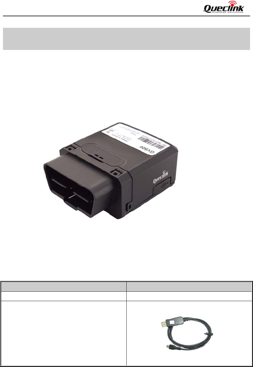
. Descript
5
00 is based
o
a
ll. GV500 c
o
n
ector, an int
e
. Parts Li
s
l
e 3: Part Lis
t
m
e
5
00 Locato
r
T
A_CABLE
_
a
l
1
O
verview
ion
o
n the OBD
I
o
ntains an O
B
e
rnal GSM a
n
F
s
t
t
_
M (Optiona
l
I
I interface
G
B
D II conne
c
n
tenna, an in
t
F
igure 1.
l
)
G
PS vehicle t
r
c
tor which c
o
t
ernal GPS a
n
A
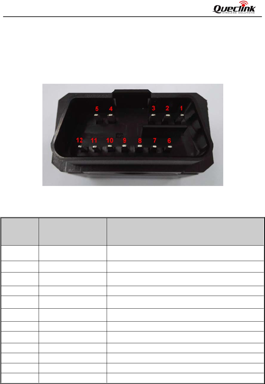
ppeara
n
Pict
r
acking devi
c
o
mplies with
n
tenna and t
h
n
ce of GV5
0
ure
48
c
e, compact
d
J1962 stand
a
h
ree LEDs.
0
0
mm*25mm*
4
d
esign and e
a
a
rd, a 10PIN
48mm
‐7‐
a
sy to
USB
GV5
0
TRA
C
2.3
.
The
L-li
n
foll
o
Tab
l
Ind
e
1
2
3
4
5
6
7
8
9
10
11
12
0
0UserManu
a
C
GV500UM00
1
. Interfac
e
GV500 has
a
n
e and J185
o
wing figure:
l
e 4: Descrip
t
e
x D
e
P
W
L
_
H
S
M
J1
K
_
H
S
G
N
G
N
M
J1
S
W
a
l
1
e
Definitio
a
n OBD II c
o
0 bus. The
Figure
2
t
ion of OBD
I
e
scription
W
R
_
line
S
_CAN_L
S_CAN_L
850_BUS-
_
Line
S
_CAN_H
N
D
N
D
S_CAN_H
850_BUS+
W
_CAN
n
o
nnector. It c
o
sequence a
n
2
. The
O
I
I Connectio
n
C
E
x
L
H
M
J
1
K
H
P
o
P
o
M
J
1
S
W
o
ntains pow
e
n
d definition
O
BD II conn
n
s
C
omment
x
ternal DC p
line of ISO
9
H
S_CAN_H l
i
M
S_CAN_L l
i
1
850 Bus ne
g
K
line of ISO
9
H
S_CAN_H l
i
o
wer and dig
o
wer and dig
M
S_CAN_H
l
1
850 Bus po
s
W
_CAN of I
e
r supply and
of the OB
D
ector on th
ower input,
8
9
141, ISO 91
4
i
ne of ISO 11
i
ne of ISO 1
1
g
ative line of
9
141, ISO 9
1
i
ne of ISO 11
ital ground
ital ground
l
ine of ISO 1
1
s
itive line of
J
SO 11898 a
n
interfaces o
f
D
II connec
t
e GV500
8
-32V
4
1-2 and IS
O
898,J1939 a
n
898 and ISO
J
1850 PWM
41-2 and IS
O
898,J1939 a
n
1
898 and IS
O
J
1850 PWM
a
n
d ISO 15765
f
CAN bus,
K
t
or are sho
w
O
14230
n
d ISO 1576
5
O
15765
and J1850
V
O
14230
n
d ISO 1576
5
O
15765
and J1850 V
P
5
‐8‐
K
-line,
w
n in
5
V
PW
5
P
W
GV
5
TRA
C
3.
G
3.1
.
Inse
the
c
5
00UserMan
u
C
GV500UM
0
G
etting S
t
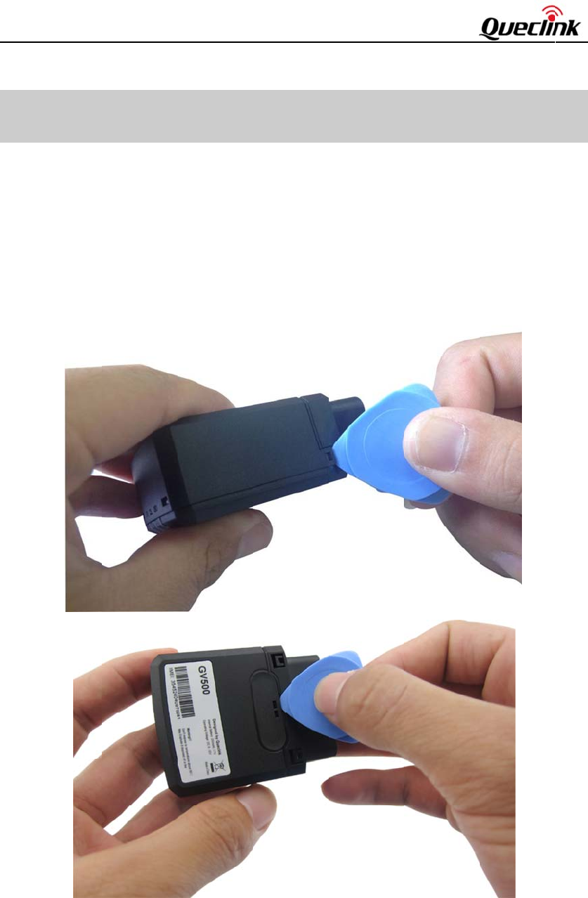
. Openin
g
rt the triang
u
c
ase unsnapp
u
al
0
01
t
arted
g
the Case
u
la
r
-pry-ope
n
ed.
er into the g
a
a
p of the cas
e
e
as shown b
e
low, push t
h
0
h
e opener up
until
GV
5
TRA
C
5
00UserMan
u
C
GV500UM
0
u
al
0
01
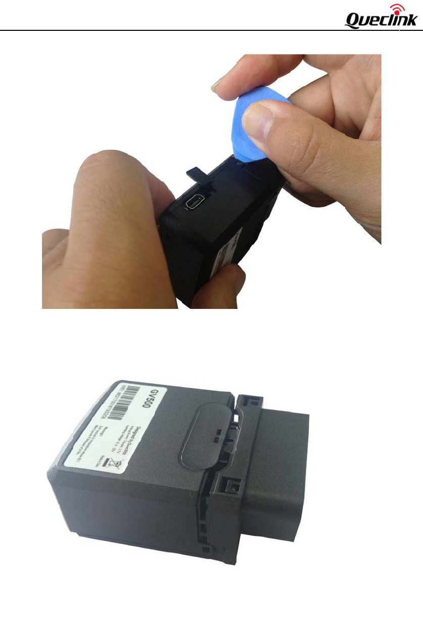
Figure 3.
Openin
g
g
the Case
1
GV
5
TRA
C
3.2
.
The
plu
g
5
00UserMan
u
C
GV500UM
0
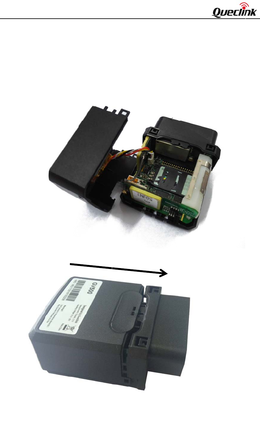
. Closing
t
battery is gl
u
g
ged in. The
s
u
al
0
01
t
he Case
u
ed to top c
o
s
tep of closin
o
ver, so befo
r
g
case is sho
w
Cl
o
r
e closing th
e
w
n as follow
i
o
sing the C
a
e
case you s
h
i
ng:
a
se
h
ould let the
2
battery con
n
n
ector
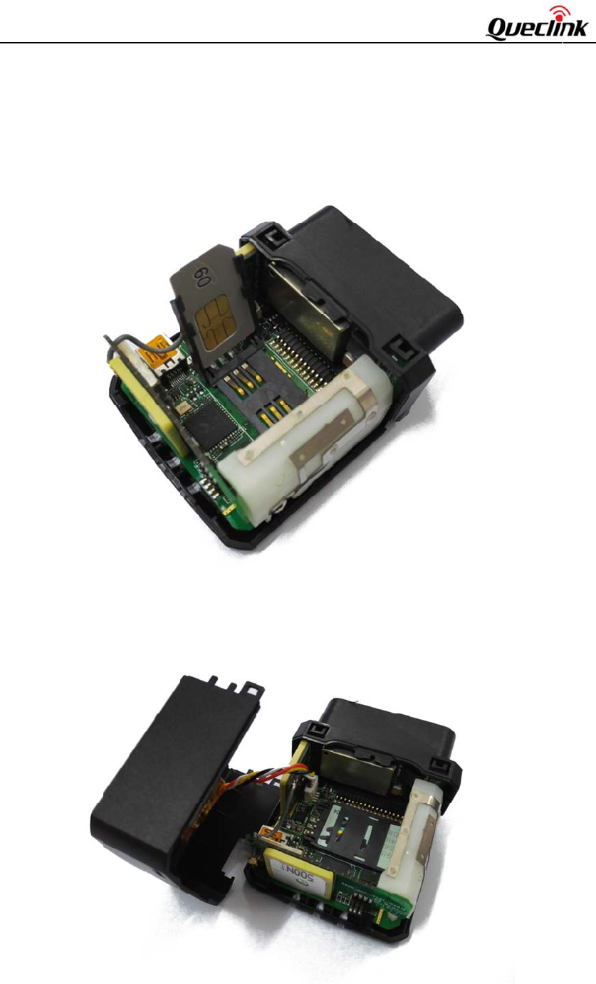
GV
5
TRA
C
3.3
.
Ope
Inse
do
w
3.4
.
The
r
5
00UserMan
u
C
GV500UM
0
. Installin
g
n the case a
n
rt the SIM
c
w
n taking car
e
. Installin
g
r
e is an inter
n
u
al
0
01
g
a SIM C
a
n
d ensure th
e
c
ard into the
e
to align the
F
g
the Inte
r
Fig
n
al backup L
i
a
rd
e
unit is not
holder as s
h
c
ut mark. Cl
o
F
igure 4.
r
nal Back
u
u
re 5. B
i
-ion battery.
powered. Sl
i
h
own below
o
se the SIM
c
SIM Card
u
p Batter
y
ackup Bat
t
i
de the hold
e
with the go
l
c
ard holder.
C
Installatio
n
y
t
ery Install
a
e
r right to o
p
l
d-colored c
o
C
lose the cas
e
n
a
tion
3
p
en the SIM
o
ntact area
fa
e
.
card.
fa
cing
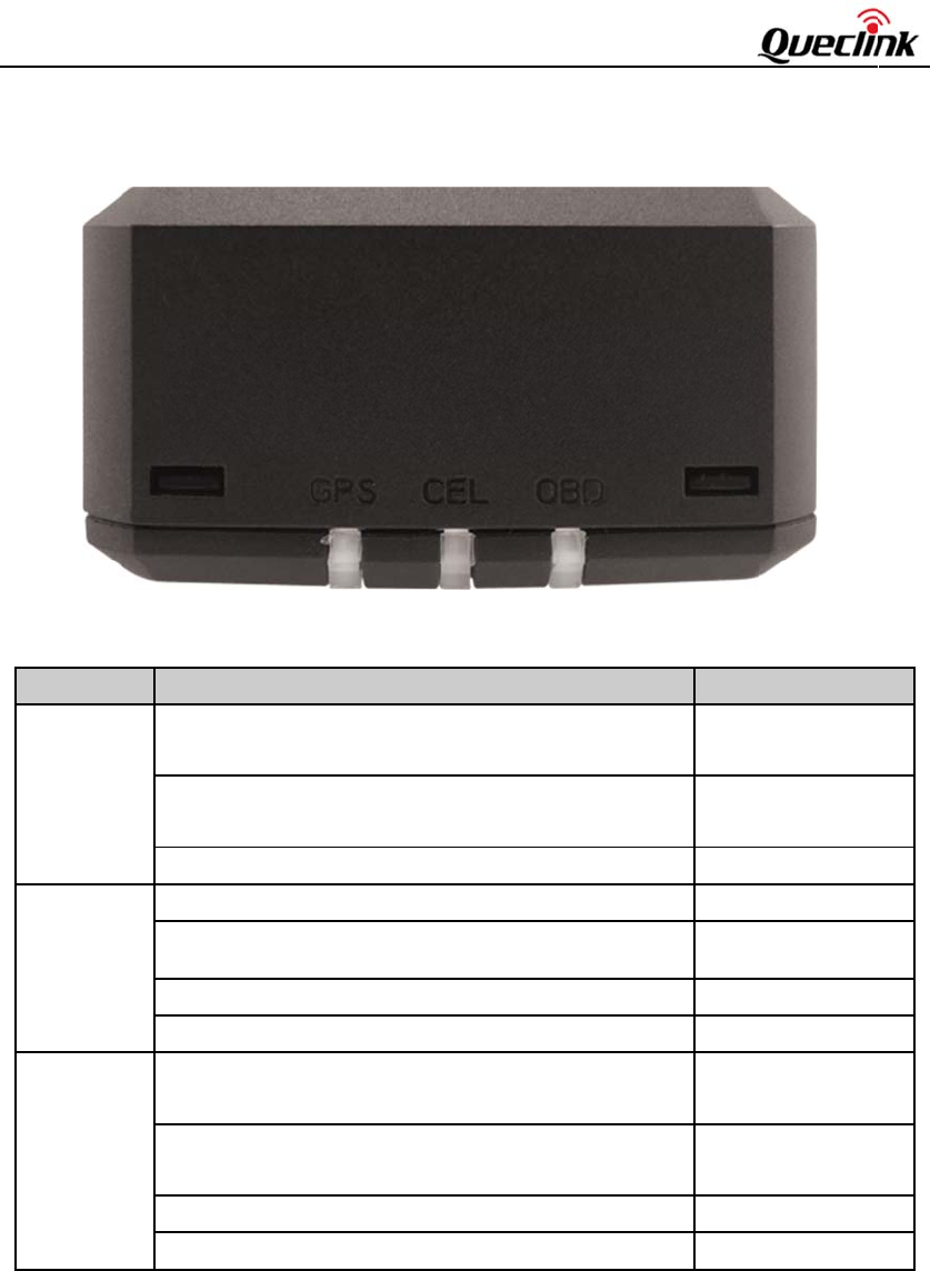
GV
5
TRA
C
3.5
.
Not
1 -
G
usin
2 -
F
3 -
S
L
C
(
n
G
(
n
O
(
n
5
00UserMan
u
C
GV500UM
0
. Device
S
e:
G
PS LED a
n
n
g the config
u
F
ast flashing
i
S
low flashin
g
L
ED
C
EL
n
ote1)
G
PS
n
ote 1)
O
BD
n
ote 1)
u
al
0
01
S
tatus LE
D
F
i
Ta
b
n
d OBD LE
D
u
ration tool.
i
s about 60m
g
is about 60
m
Device stat
u
Device is se
a
Device has
r
SIM card ne
GPS chip is
GPS sends
n
GPS chip is
GPS chip h
a
No external
than 3.46V.
G
No externa
l
below 3.55
V
External po
w
External po
w
D
i
gure 6.
b
le5:Definit
i
D
and CEL L
E
s ON/ 780m
s
m
s ON/ 1940
m
u
s
a
rching GS
M
r
egistered to
G
eds pin code
powered of
f
n
o data or dat
a
searching G
P
a
s gotten GP
S
power and i
n
G
V500 is po
w
l
power an
d
V
w
er in and in
t
w
er in and in
t
GV500 LE
D
i
onofDevic
e
E
D can be c
o
s
OFF
m
s OFF
M
network
G
SM networ
k
to unlock.
a format err
o
P
S info.
S
info.
n
ternal b
a
tter
y
w
er off.
d
internal b
a
t
ernal batter
y
t
ernal batter
y
D
on the C
a
statusand
L
o
nfigured to
k
.
o
r.
y
voltage is l
o
a
ttery volta
g
y
is charging
y
is fully char
g
se
ED
turn off afte
r
LED
Fast
f
(Not
e
Slow
(Not
e
ON
OFF
Slow
Fast
f
ON
o
wer OFF
g
e is Slow
Fast
f
g
ed ON
4
r
a period o
f
status
f
lashing
e
3)
flashing
e
4)
flashing
f
lashing
flashing
f
lashing
f
time

GV
5
TRA
C
4.
O
4.1
.
GV
5
SA
E
4.2
.
GV
5
1)
2)
3)
4)
5)
6)
7)
8)
9)
10)
11)
12)
13)
Not
e
5
00UserMan
u
C
GV500UM
0
O
BD II-r
e
. Commu
n
5
00 could m
o
E
but also so
m
No.
1
2
3
4
5
6
7
8
9
10
11
12
13
. OBD II P
5
00 can read
Vehicle ide
n
OBD Power
Parameter i
d
Revolution
s
Vehicle spe
Engine Co
o
Fuel Consu
m
Distance St
a
Malfunctio
n
Diagnostic
T
Throttle Po
s
Engine Loa
d
Fuel Level
I
e
:
u
al
0
01
e
lated fe
a
n
ication P
o
nitor the O
B
m
e special pr
o
Proto
c
J1850
J1850
ISO 9
1
ISO 1
4
ISO 1
4
ISO 1
5
ISO 1
5
ISO 1
5
ISO 1
5
J1939
CAN
_
CAN
_
VW T
arameter
s
the followin
g
n
tification nu
m
Voltage
d
entification
s
per minute
o
ed
o
lant Temper
a
m
ption
a
tistics
n
Indicator L
a
T
rouble Cod
e
s
ition
d
I
nput
a
tures
rotocols
B
D II system
v
o
tocols. The
l
c
ol
PWM
VPW
1
41-2
4
230
4
230
5
765
5
765
5
765
5
765
_
USER1
_
USER2
P
2.0
Table 6: Co
m
s
g
parameters
m
be
r
(VIN):
(PID)
o
f the engine
a
ture
a
mp (MIL)
e
s (DTC)
via not only
l
ist of protoc
o
Co
m
41.6
k
10.4
k
5 Ba
u
5 Ba
u
Fast
ID 1
1
ID 2
9
ID 1
1
ID 2
9
ID 2
9
11*
b
11*
b
Volk
m
munication
P
through OB
D
(RPM)
c
ommunicat
i
o
ls is shown
m
ment
k
b/s FOR
D
k
b/s GM/C
h
u
d init auto
m
u
d init 10.4k
b
init 10.4kb/s
1
bits 500kb
9
bits 500kb
1
bits 250kb
9
bits 250kb
9
bit 250kb
b
its 125*kb
b
its 50*kb
s
wagen CA
N
P
rotocols Li
s
D
II system.
on protocols
a
s follow:
h
rysle
r
m
atic baud rat
e
b
/s
N
protocol
s
t
5
which defin
e
e
e
d by

GV
5
TRA
C
1 -
T
VI
N
retu
r
2 -
D
MI
L
5
00UserMan
u
C
GV500UM
0
T
he VIN is t
h
N
from OBD
I
r
n from OB
D
D
istance Stat
i
L
is activated
u
al
0
01
h
e unique ide
n
I
I system, be
c
D
II system.
i
stics: GV50
0
and distance
n
tifier of Ve
h
c
ause the Ve
h
0
could get t
h
accumulate
d
h
icle. Please
n
h
icle manufa
c
h
e distance i
n
d
since DTCs
n
ote that not
a
c
turers are re
two cases:
d
were cleare
d
a
ll Vehicle s
u
s
ponsible fo
r
istance accu
m
d
.
6
u
pport gettin
g
r
defining the
m
ulated sinc
e
g
the
data
e
RFExposureStatement:
Fortheproduct,undernormaluseconditionisatleast20cmawayfromthebodyoftheuser,the
usermustkeepingatleast20cmdistancetotheproduct.
ThisdevicecomplieswithPart15oftheFCCRules.Itsoperationissubjecttothefollowingtwo
conditions:
(1) Thisdevicemaynotcauseharmfulinterference,and
(2) Thisdevicemustacceptanyinterferencereceived,includinginterferencethatmaycause
undesiredoperation.
Note:
THEGRANTEEISNOTRESPONSIBLEFORANYCHANGESORMODIFICATIONSNOTEXPRESSLY
APPROVEDBYTHEPARTYRESPONSIBLEFORCOMPLIANCE.SUCHMODIFICATIONSCOULDVOID
THEUSER’SAUTHORITYTOOPERATETHEEQUIPMENT
ThisproducthasbeentestedandfoundtocomplywiththelimitsforPart15oftheFCCRules.
Theselimitsaredesignedtoprovidereasonableprotectionagainstharmfulinterferenceina
residentialinstallation.Thisproductgenerates,uses,andcanradiateradiofrequencyenergyand,
ifnotinstalledandusedinaccordancewiththeinstructions,maycauseharmfulinterferenceto
radiocommunications.However,thereisnoguaranteethatinterferencewillnotoccurina
particularinstallation.Ifthisproductdoescauseharmfulinterferencetoradioortelevision
reception,whichcanbedeterminedbyturningtheequipmentoffandon,theuserisencouraged
totrytocorrecttheinterferencebyoneormoreofthefollowingmeasures:
—Reorientorrelocatethereceivingantenna.
—Increasetheseparationbetweentheequipmentandreceiver.
—Connecttheequipmentintoanoutletonacircuitdifferentfromthattowhichthereceiveris
connected.
—Consultthedealeroranexperiencedradio/TVtechnicianforhelp.