Quectel Wireless Solutions 201706SC20A LTE Module User Manual
Quectel Wireless Solutions Company Limited LTE Module
UserManual.wiki
>
Quectel Wireless Solutions
>
201706SC20A User Manual
>
User manual
Contents
1.
User manual
2.
Users Manual
3.
User Manual
User manual
Navigation menu
Upload a User Manual
Namespaces
Wiki Guide
HTML
PDF
Info
Views
User Manual
Discussion / Help
Navigation
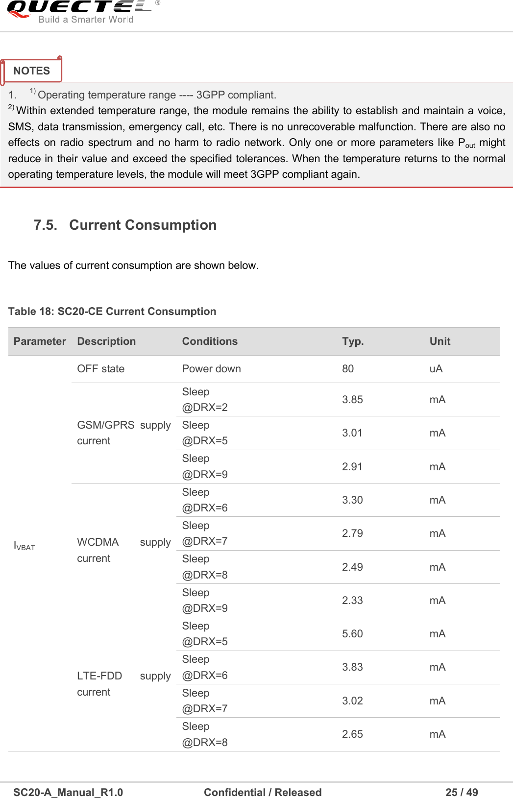
![SC20-A_Manual_R1.0 Confidential / Released 11 / 49 Figure 1: Functional Diagram 2.4. Evaluation Board In order to help you to develop applications with SC20, Quectel supplies an evaluation board (SMART-EVB), RS-232 to USB cable, USB data cable, power adapter, earphone, antenna and other peripherals to control or test the module. For details, please refer to document [1].](https://usermanual.wiki/Quectel-Wireless-Solutions/201706SC20A.User-manual/User-Guide-3508018-Page-12.png)
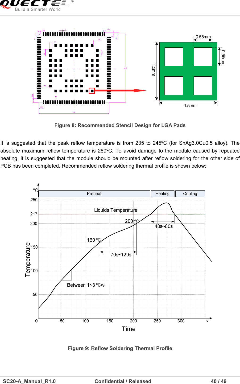
![SC20-A_Manual_R1.0 Confidential / Released 39 / 49 9 Storage, Manufacturing and Packaging 9.1. Storage SC20 is stored in a vacuum-sealed bag. The restrictions of storage condition are shown as below. 1. Shelf life in sealed bag is 12 months at < 40ºC/90%RH. 2. After this bag is opened, devices that will be subjected to reflow soldering or other high temperature process must be: Mounted within 72 hours at factory conditions of ≤ 30ºC/60%RH. Stored at < 10% RH. 3. Devices require baking before mounting, if: Humidity indicator card is > 10% when ambient temperature is 23ºC±5ºC. Mounting cannot be finished within 72 hours at factory conditions of ≤ 30ºC/60% RH. 4. If baking is required, devices may be baked for 48 hours at 125ºC±5ºC. 9.2. Manufacturing and Welding Push the squeegee to apply the solder paste on the surface of stencil, thus making the paste fill the stencil openings and then penetrate to the PCB. The force on the squeegee should be adjusted properly so as to produce a clean stencil surface on a single pass. To ensure the module soldering quality, the thickness of stencil at the hole of the module pads should be 0.18mm. For details, please refer to document [3]. As plastic package cannot be subjected to high temperatures, the package must be removed from devices before high temperature (125ºC) baking. If shorter baking time is desired, please refer to IPC/JEDECJ-STD-033 for baking procedure. NOTE](https://usermanual.wiki/Quectel-Wireless-Solutions/201706SC20A.User-manual/User-Guide-3508018-Page-40.png)