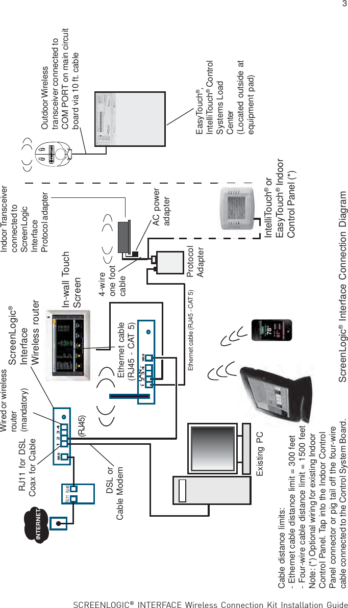
Quest Technical Sales and QTS0000LINK Wireless RS-485 Transceiver User Manual VIPER WIRELESS MANUAL 10 4 12

Quest Technical Sales and Marketing, Inc. Wireless RS-485 Transceiver VIPER WIRELESS MANUAL 10 4 12

User Manual

SCREENLOGIC® INTERFACE Wireless Connection Kit Installation GuideIMPORTANT SAFETY INSTRUCTIONSREAD AND FOLLOW ALL INSTRUCTIONSSAVE THESE INSTRUCTIONSINSTALLATION GUIDESCREENLOGIC® INTERFACEWIRELESS CONNECTION KITFOR INTELLITOUCH® AND EASYTOUCH® CONTROL SYSTEMS
SCREENLOGIC® INTERFACE Wireless Connection Kit Installation GuideTechnical SupportPhone: (800) 831-7133Web sites:  visit www.pentairpool.com and www.staritepool.comContentsOverview ........................................................................................................... 1Wireless Connection Kit Contents ...................................................................... 1Summary Installation Steps ................................................................................ 2ScreenLogic Interface Connection Diagram ....................................................... 3Mount the Outdoor Wireless Transceiver and Connect to theIntelliTouch or EasyTouch Load Center .............................................................. 4   Connect the Indoor Wireless Transceiver to the ScreenLogic    Interface Protocol Adapter ................................................................................. 8Connect the Indoor Wireless Transceiver to the ScreenLogic    Interface Protocol Adapter ................................................................................. 8   Cradle/Desk Mount the Indoor Wireless Transceiver ........................................... 8Wall Mount the Indoor Wireless Transceiver........................................................ 8i FCC Regulatory Safety NoticeThis equipment has been tested and found to comply with the limits for a Class B digitaldevice, pursuant to Part 15 of the FCC Rules. These limits are designed to providereasonable protection against harmful interference in a residential installation. Thisequipment generates, uses and can radiate radio frequency energy and, if not installedand used in accordance with the instructions, may cause harmful interference to radiocommunications. However, there is no guarantee that interference will not occur in aparticular installation. If this equipment does cause harmful interference to radio or televisionreception, which can be determined by turning the equipment off and on, the user isencouraged to try to correct the interference by one or more of the following measures:• Reorient or relocate the receiving antenna.• Increase the separation between the equipment and receiver.• Connect the equipment into an outlet on a circuit different from that to which thereceiver is connected.• Consult the dealer or an experienced radio/TV technician for help.• Modifications not expressly approved by the party responsible for FCC compliancecould void the user’s authority to operate the equipment.Industry Canada StatementThe device complies with industry Canada’s License Exempt RSSs. Operation is subject to thefollowing: (1) This device may not cause interference; and (2) This device must acceptinterference that may cause undesired operation of the device.This Class B digital apparatus complies with Canadian ICES-003.Cet appareil numérique de laclasse B est conforme à la norme NMB-003 du Canada. The term “IC” before the certification /registration number only signifies that the Industry Canada technical specifications were met.Le dispositif est conforme à la licence d'Industrie Canada Exempt CNR. Le fonctionnement estsoumis à la suivante. (1) Ce ne doit pas provoquer d'interférences ; et (2) Cet appareil doitaccepter les interférences qui peuvent causer un mauvais fonctionnement de l'appareil.Notice: In order to comply with FCC RF Exposure requirements, a minimum separationdistance of 8 in (20 cm) must be maintained between the equipment and all persons duringnormal operation.
SCREENLOGIC® INTERFACE Wireless Connection Kit Installation Guide1ScreenLogic® Interface Wireless Connection Kit OverviewThe ScreenLogic® Interface Wireless Connection interface consists of anindoor and outdoor wireless 902-928 MHz wireless transceiver.Note: The wireless transceivers ship from the factory as a matched pair.The ID numbers on each transceiver must be the same number to functioncorrectly. If needed, the transceivers are replaced as a matched pair . Formore information, call Customer Support (880) 831.7133.The indoor and outdoor transceivers provide a wireless connectionbetween the ScreenLogic Interface Protocol adapter and the IntelliTouch®or EasyTouch® Control System Load Center located at the equipment pad.This wireless connection eliminates the existing hard wire connection frominside your home to the equipment pad.4XMounting hardware2XOutdoorTransceiverenclosureIndoor transceiver and base AC transformer Outdoor Cable(white - 10 ft.) NOTE (*): ID numberson Indoor and Outdoortransceiver board mustmatchIndoor hardwareCable (for connection toScreenLogic® InterfaceProtocol Adapter(purchased separately) 2X 4X2XIn this Installation GuideThis Installation Guide provides installation instructions for the ScreenLogic®Interface Wireless Connection kit.• For the ScreenLogic Interface system operating instructions, refer to theScreenLogic Interface User’s Guide (P/N 520493)SCREENLOGIC   INTERFACE®ScreenLogic InterfaceProtocol Adapter(purchased separately)ScreenLogic Interface Wireless Connection Kit ContentsWireless Connection Kit ContentsThe following items are included in the Wireless Connection kit:•One ScreenLogic Interface indoor wireless transceiver with AC poweradapter and 1 ft. long cable with attached plugs.• One ScreenLogic Interface outdoor wireless transceiver with10 ft. cable, enclosure and mounting hardware.• ScreenLogic Interface Wireless Connection Installation Guide(this manual).
SCREENLOGIC® INTERFACE Wireless Connection Kit Installation Guide2Antenna location Indoor Wireless TransceiverPWR: Green LED on: Power is on to the unit.• PWR LED blinking: Not linked or lost link,   attempting to link or relink, no response.• PWR LED blinking, TX and/or RX LED blinking:   not linked, attempting to link, getting responses.• PWR LED on steady: Linked.• PWR LED blinking: Lost link, Attempting to relink.RX: Yellow LED indicates the unit is receiving data.TX: Green LED indicates the unit is transmitting data.Note: ScreenLogic Interface Indoor Wireless Transceiver (Note: For optimumperformance, mount indoor transceiver upright in the cradle or on an indoorwall).Summary Installation StepsThe ScreenLogic® Interface connection diagram on page 3 shows thetransceiver locations and connections. To install the ScreenLogic InterfaceWireless Connection kit:RS-485 Connector(to Protocol Adapter)• Mount the outdoor transceiver antenna module near the IntelliTouch®or EasyTouch® Control System Load Center (see page 4 formounting instructions).  Using the provided 10 ft. cable, connect thetransceiver to the COM port connector located in the IntelliTouch  orEasyTouch Control System Load Center (see page 7).• Connect the ScreenLogic Interface indoor wireless transceiver to theScreenLogic Interface Protocol adapter using the 12 in cable. Plugthe AC power adapter into an AC wall-outlet and into the wirelesstransceiver unit to power up the unit (see page 8).ID number(Outdoor transceiver)IMPORTANT NOTICE: Be sure theyellow ID label (9-digit ID numberXXXXXXXXX) located to the right ofthe RS-485 connector on the front sideof the Indoor transceiverenclosure and the ID numberon the  ScreenLogic Interface OutdoorWireless transceiver are the same. Seepage 1 for label  location.LED Indicators Description:
SCREENLOGIC® INTERFACE Wireless Connection Kit Installation Guide1234WANRJ11 RJ45INTERNET1234WAN  - LAN -Wired or wirelessrouter(mandatory)RJ11 for DSLCoax for CableIn-wall TouchScreenOutdoor Wirelesstransceiver connected toCOM PORT on main circuitboard via 10 ft. cableProtocolAdapterScreenLogic®InterfaceWireless routerExisting PCEthernet cable (RJ45 - CAT 5)Ethernet cable(RJ45 - CAT 5)DSL orCable Modem(RJ45)Cable distance limits:- Ethernet cable distance limit = 300 feet- Four-wire cable distance limit = 1500 feetNote: (*) Optional wiring for existing IndoorControl Panel. Tap into the Indoor ControlPanel connector or pig tail off the four-wirecable connected to the Control System Board.Indoor Transceiverconnected toScreenLogicInterfaceProtocol adapterEasyTouch®,IntelliTouch® ControlSystems LoadCenter(Located outside atequipment pad)34-wireone footcableAC poweradapterScreenLogic® Interface Connection DiagramIntelliTouch® orEasyTouch® IndoorControl Panel (*)
SCREENLOGIC® INTERFACE Wireless Connection Kit Installation Guide4Mount the Outdoor Wireless Transceiver and Connect to theIntelliTouch® or EasyTouch® Control System Load CenterThe following describes how to mount and connect the outdoor transceiverto the IntelliTouch or EasyTouch Control System Load Center.Mounting the Outdoor Transceiver ModuleThe  outdoor transceiver is a two-way radio device with an attached antenna thatcommunicates with the IntelliTouch or EasyTouch Control System via the10 ft. four-conductor communication cable.Outdoor tranceiver mounting location: Choose a convenient location on a flatvertical surface near the Load Center at a minimum of 5 ft above ground level tooptimize the transmit and receive operating range. For optimum performanceposition the Outdoor transceiver with an unobstructed line-of-sight propagationbetween the Indoor and Outdoor tranceiver.1. Position the back plate against the mounting surface so that thetransceiver is oriented in an upright position with the antennapointing upwards. Use a pencil to mark the four mounting points.Drill four 3/16 in. diameter holes into the mounting surface and insertthe four plastic anchors provided in the kit.Note: To avoid signal interference, mount the transceiver aminimum of 10 feet away from the load center, any metalsurface/structure, or air blower located in the immediate areaof the equipment pad.2. Position the back plate over the mounting points and secure it withthe four mounting screws provided in the kit.3. Carefully position the transceiver circuit board into the mounted backplate. Route the communication cable wire up through the lower exithole at the bottom of the back plate. Carefully pull the communicationcable out the lower hole and position the circuit board in the backplate.4. Proceed to “Connect the wireless transceiver communicationcable to the COM Port on automation control systems circuitboard” on page 6.5. Slide the case over the circuit board and antenna into the back plate.Secure the circuit board in the case using the two retaining screws.
SCREENLOGIC® INTERFACE Wireless Connection Kit Installation Guide5Outdoor Wireless TransceiverCaseWireless transceivercase retainingscrews (x2)Back plate formounting circuitboardOutdoor wireless transceivercircuit boardConnect 4-conductorcommunication cable toterminal screws.OutdoorTransceiverconnectorCOM PORT (RS-485)screw terminal connector onIntelliTouch® or EasyTouch®Control System circuit boardBLKREDYELGRNBLK  (GND - PIN 1)GRN (- DT -  PIN 2)YEL  (+ DT  - PIN 3)RED  (15 V  -  PIN 4)OutdoorTransceivercircuitboard
SCREENLOGIC® INTERFACE Wireless Connection Kit Installation GuideWARNING Switch OFF the main power to the Load Centerbefore making any connections.1. Switch OFF the AC power to the enclosure at the main house panelcircuit breaker.2. Unlatch the front door latch and open the front door. Remove the tworetaining screws from the High-Voltage Cover Panel and remove thepanel.3. Loosen the two retaining screws securing from the top edge of theOutdoor Control Panel. Fold down the Outdoor Control Panel toaccess the circuit board sockets connectors for the electricalconnections. Remove the panel from the enclosure (see illustrationbelow).4. Route the four conductor transceiver connection cable into the lowerplastic grommet, up through the low voltage raceway to the systemcircuit board.6Connect the wireless transceiver communication cable to the COMPort on automation control system circuit boardIntelliTouch® or EasyTouch® Control System Load CenterRetainingscrewsHIGH -VOLTAGEFRONT COVERPANELOutdoorControl Panelretainingscrew (x2)Outdoortransceivercommunicationcable(connect toCOM port)OutdoorControl PanelGrommet(under side ofLoad CenterInside LowvoltageracewayLatch
SCREENLOGIC® INTERFACE Wireless Connection Kit Installation Guide5. Strip the leads of the communication cable wires back ¼ in. Insert thewires into the connector screw terminals. Using a small flat-bladescrewdriver, secure the wires with the COM PORT (J7/J8) terminalscrews. Note: Multiple wires may be inserted into a single screwterminal. Be sure to match the color-coding of the wires:Pin 4 - Red = +15 VDCPin 3 - Yellow = +DTPin 2 - Green = -DTPin 1 - Black = GND7IntelliTouch® (J7/J8) orEasyTouch® ControlSystem COM Ports(J20) screw terminalconnectorNote: Multiple wires may beinserted into a single screw COMPORT terminal. However, this cancause an intermittent connection.Note: For additional COM ports,an optional Serial COM PortExpansion Board (P/N 520818)can be installed in the low voltagecompartment.6. After the communication cable connection has been completed; closethe Outdoor Control Panel and tighten the two retaining screws.Reinstall the High Voltage Panel: Insert the panel’s three tabs into thelower slots on the enclosure. Secure the panel with the two (2)retaining screws. Close the front door and secure it with the latch.7. Switch ON AC power to the Load Center.8. After the Power Center is powered up the Wireless Controller willautomatically synchronize with the system and will be ready foroperation.  Note: The initial connection can take up to 2-3minutes.9. Proceed to the “Connecting the ScreenLogic Interface IndoorWireless Transceiver to the ScreenLogic Interface ProtocolAdapter” on page 8.
SCREENLOGIC® INTERFACE Wireless Connection Kit Installation Guide8Connecting the Indoor Wireless Transceiver and Protocol AdapterConnect the Indoor Wireless Transceiver to the ScreenLogic®Interface Protocol AdapterConnect the ScreenLogic Interface indoor wireless transceiver to theScreenLogic Interface Protocol adapter as follow:1. Using the 1 ft. connection cable, connect one end of the cable to theProtocol Sdapter and the other end to the Indoor WirelessTransceiver. See Figure 1 and Figure 2. The cable plugs are keyed foreasy connection.2. Plug the 120 VAC Power Adapter into an AC grounded electricaloutlet.Wall Mount the Indoor Wireless Transceiver (Figure 2 and Figure 3)1. Cut out the wall mounting templating from the next page. Place the templateon an indoor flat surface or wall and mark the two screw hole positions.2. Drill two holes (0.223 in) 2-1/2 inches apart as shown on the template (seeFigure 3 on next page).3. Insert the wall plugs into both wall screw holes.4. Insert the screws into the wall plug. Don’t insert the screws all the way intothe wall, leave about 1/16 in for the wireless transceiver to hang on the headof the screws (see Figure 2 on next page).5. Mount the wireless transceiver onto both screw heads.Cradle/Desk Mount the Indoor Wireless Module (Figure 1)1. Insert the power cable into the base of the Indoor transceiver cradle. Fastenthe cable into the cradle slot (see Figure 1 on next page).2. Insert the connection cable into the base of the Indoor transceiver cradle.Fasten the cable into the cradle slot (see Figure 1 on next page).3. Place the cradle on a table or desk.  Note: Keep the cradle and Indoortransceiver clear of all objects for two feet.Mount the Indoor Wireless Transceiver in its cradle as follows:Mount the Indoor Wireless Transceiver on an indoor wall as follows:SCREENLOGIC   INTERFACE®Connection cable (1 ft)(provided in kit)120 VACPower AdapterIndoor Wireless TransceiverProtocol Adapter
SCREENLOGIC® INTERFACE Wireless Connection Kit Installation Guide9Wall Mount the Indoor Wireless Transceiver (Continued) 2½ in Figure 3: Wall Mount Template for Indoor Wireless TransceiverIndoor Wireless Module Mounting Screw LocationFigure 2: Wall Mount the Indoor Wireless TransceiverFigure 1: Cradle/Desk Mount the Indoor Wireless TransceiverHang module onscrew head(approx. 1/16 infrom wall surface) 116" (0.41 cm)Mounting screw/plug (2x)Screw hole (x2)Wall screwhole (2x)Secure AC powercable in slot in baseSecurecommunicationcable in slot in base120 VACpower adapterProtocol adapterSCREENLOGIC   INTERFACE®
SCREENLOGIC® INTERFACE Wireless Connection Kit Installation Guide1620 HAWKINS AVE., SANFORD, NC 27330 • (919) 566-800010951 WEST LOS ANGELES AVE., MOORPARK, CA 93021 • (805) 553-5000WWW.PENTAIRPOOL.COMAll Pentair trademarks and logos are owned by Pentair or by one of its global affiliates. Pentair AquaticSystems™, ScreenLogic®, EasyTouch® and IntelliTouch® are trademarks and/or registered trademarks ofPentair Water Pool and Spa, Inc. and/or its affiliated companies in the United States and/ or other countries.iPhone® is a registered trademark of Apple Corporation. Unless expressly noted, names and brands of thirdparties that may be used in this document are not used to indicate an affiliation or endorsement between theowners of these names and brands and Pentair Water Pool and Spa, Inc. Those names and brands may bethe trademarks or registered trademarks of those third parties. Because we are continuously improving ourproducts and services, Pentair reserves the right to change specifications without prior notice. Pentair is anequal opportunity employer.© 2016 Pentair Water Pool and Spa, Inc.  All rights reserved.This document is subject to change without notice.P/N 522633  REV. A  1/2016*522633*

Navigation menu