Quirky WR001 Wink Relay User Manual
Quirky, Inc. Wink Relay
UserManual.wiki
>
Quirky
>
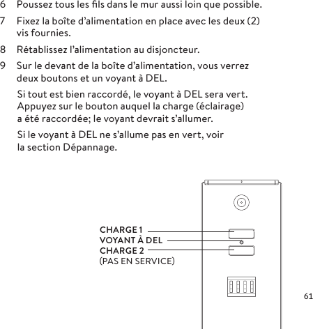
WR001 User Manual
User Manual
Navigation menu
Upload a User Manual
Namespaces
Wiki Guide
HTML
PDF
Info
Views
User Manual
Discussion / Help
Navigation


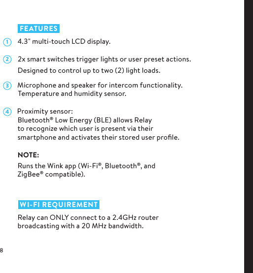
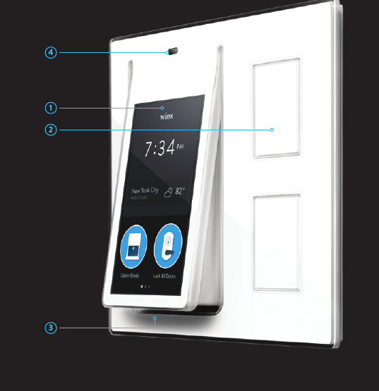
![ INSIDE RELAY AND WHAT IT DOESCentral processor host (Freescale i.MX6)This board runs Android as the underlying OS to launch a custom build of the Wink app. System memory hostDDR3 512M x 64 NAND Flash 2GB Serial NOR Flash 4MB4.3" capacitive multi- touch screen [MRD DISP 001]The touch screen is the central interaction point for this product. With a quick swipe, you can switch between your personalized dashboard and various screens that control local light loads and many other functions.](https://usermanual.wiki/Quirky/WR001/User-Guide-2401956-Page-12.png)
![Bluetooth / Wi-Fi combo chip (Semco SWB B53 based on Broadcom BCM4334) [MRD SW 002]This chip provides Wi-Fi, Bluetooth, and BLE (Bluetooth Low Energy) connectivity. Bluetooth connectivity allows a wider spectrum of products to interact with the Wink platform on Relay. It also lets Relay identify multiple users and create custom experiences based on whose Bluetooth-equipped smartphone is nearby.ZigBee module (Silicon Images EM357 Ember) [MRD SW 003]The use of ZigBee allows you to add support for existing products, such as wireless light bulbs, as well as other smart/connected home products in the future. The use of ZigBee also acts as a passive extender for other ZigBee products you may already own.](https://usermanual.wiki/Quirky/WR001/User-Guide-2401956-Page-13.png)
![2x smart switches These switches can control local loads (the lights tied to your previous switch) or be configured to operate virtually any compatible smart product that reacts to on/o switches: garage door openers, smart light bulbs, smart power strips, etc. Motion/proximity sensor [MRD INP 001]The motion/proximity IR sensor tells Relay when you’re approaching, giving the unit time to wake up and display your personalized dashboard.2x mechanical AC relays The AC relays are your light switches. Relay, when given the signal, switches the local light loads on and o. This signal can come from the local buttons, the touch screen, or any other device running the Wink app.](https://usermanual.wiki/Quirky/WR001/User-Guide-2401956-Page-14.png)
![AC/DC converterThe converter is how the light switch is powered. The AC power from the gang box is converted to DC.Temperature & humidity sensorTemperature and humidity sensors put even more data about your home at your fingertips.Microphone [MRD INP 003]The microphone provides a voice recording opportunity as well as the ability to incorporate an internal intercom system. Speaker [MRD OUT 001]The speaker allows for the ability to incorporate intercom operability and other listening functions.](https://usermanual.wiki/Quirky/WR001/User-Guide-2401956-Page-15.png)


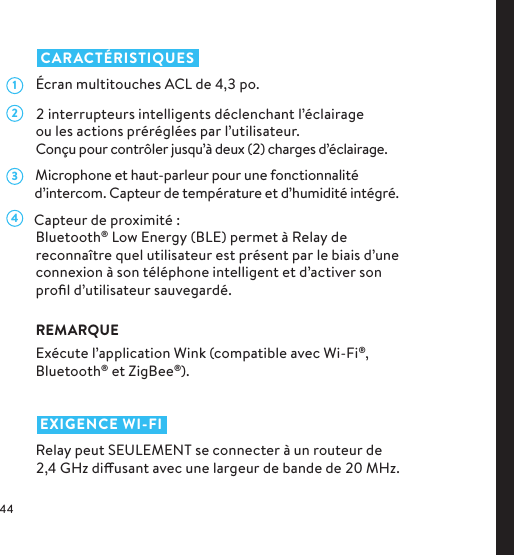

![ L’INTÉRIEUR DE RELAY ET SON RÔLEHôte d’unité centrale de traitement (Freescale i.MX6)Cette unité permet à Relay d’exécuter Android comme système d’exploitation sous-jacent et lancer une version personnalisée de l’application Wink. Cette application vise cette utilisation particulière, mais permettra l’ajout de tous les produits qui sont compatibles avec Wink.Hôte de la mémoire systèmeDDR3 512M x 64 NAND Flash 2Go Serial NOR Flash 4MoÉcran tactile multitouches capacitif de 4,3po [MRDDISP001]L’écran tactile est le point central d’interaction pour ce produit. Avec un glissement rapide de votre doigt, vous pouvez substituer votre tableau de bord personnalisé avec les écrans variés qui permettent le contrôle de charges d’éclairage locales et plusieurs autres fonctions.](https://usermanual.wiki/Quirky/WR001/User-Guide-2401956-Page-48.png)
![Puce combinée Bluetooth/Wi-Fi (Semco SWBB53 basé sur Broadcom BCM4334) [MRDSW002]Cette puce fournit la connectivité Wi-Fi, Bluetooth et BLE (Bluetooth Low Energy). La connectivité Bluetooth permet l’interaction d’une plus grande gamme de produits avec la plateforme Wink sur Relay. Elle permet aussi à Relay d’identifier plusieurs utilisateurs et de créer des expériences personnalisées dépendant des téléphones intelligents munis de Bluetooth qui se trouvent à proximité.Module ZigBee (Images Silicon EM357 Ember) [MRDSW003]L’utilisation de ZigBee vous permet d’ajouter un soutien aux produits existants comme les ampoules sans fil ainsi que d’autres produits intelligents ou branchés pour la maison à l’avenir. Le module ZigBee sert également de remplacement passif pour les autres produits ZigBee que vous possédez peut-être déjà.](https://usermanual.wiki/Quirky/WR001/User-Guide-2401956-Page-49.png)
![2 interrupteurs intelligents Ces interrupteurs peuvent contrôler des charges locales (l’éclairage lié à votre interrupteur précédent) ou être configurés pour faire fonctionner virtuellement tout produit intelligent compatible qui réagit aux interrupteurs: ouvre-porte de garage, ampoules intelligentes, barre d’alimentation intelligente, etc. Capteur de mouvement/proximité [MRDINP001]Le capteur de mouvement/proximité IR avise Relay lorsque vous vous approchez pour interagir, donnant à l’unité le temps de s’activer et d’acher votre tableau de bord personnalisé.2 relais mécaniques CA Les relais CA sont vos commutateurs d’éclairage. Relay, lorsqu’il reçoit le signal, allume et éteint les charges d’éclairage locales. Ce signal peut venir des boutons locaux, de l’écran tactile ou de tout autre appareil qui exécute l’application Wink.](https://usermanual.wiki/Quirky/WR001/User-Guide-2401956-Page-50.png)
![Convertisseur CA/CCLe convertisseur permet d’alimenter l’interrupteur d’éclairage. L’alimentation CA du boîtier est convertie en CC.Capteur de température et d’humiditéLes capteurs de température et d’humidité mettent encore plus de données sur votre maison à votre portée.Microphone [MRDINP003]Le microphone fournit une occasion d’enregistrement de la voix ainsi que la capacité d’incorporer un système d’intercom interne. Haut-parleur [MRDOUT001]Le haut-parleur permet la capacité d’incorporer une opération d’intercom et d’autres fonctions d’écoute.](https://usermanual.wiki/Quirky/WR001/User-Guide-2401956-Page-51.png)