R F Technologies CBTX Proximity Reader User Manual 0510 1086 B Series 7 0 Software Users Guide
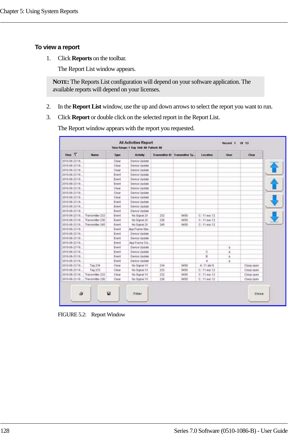
R F Technologies Inc Proximity Reader 0510 1086 B Series 7 0 Software Users Guide
UserManual.wiki
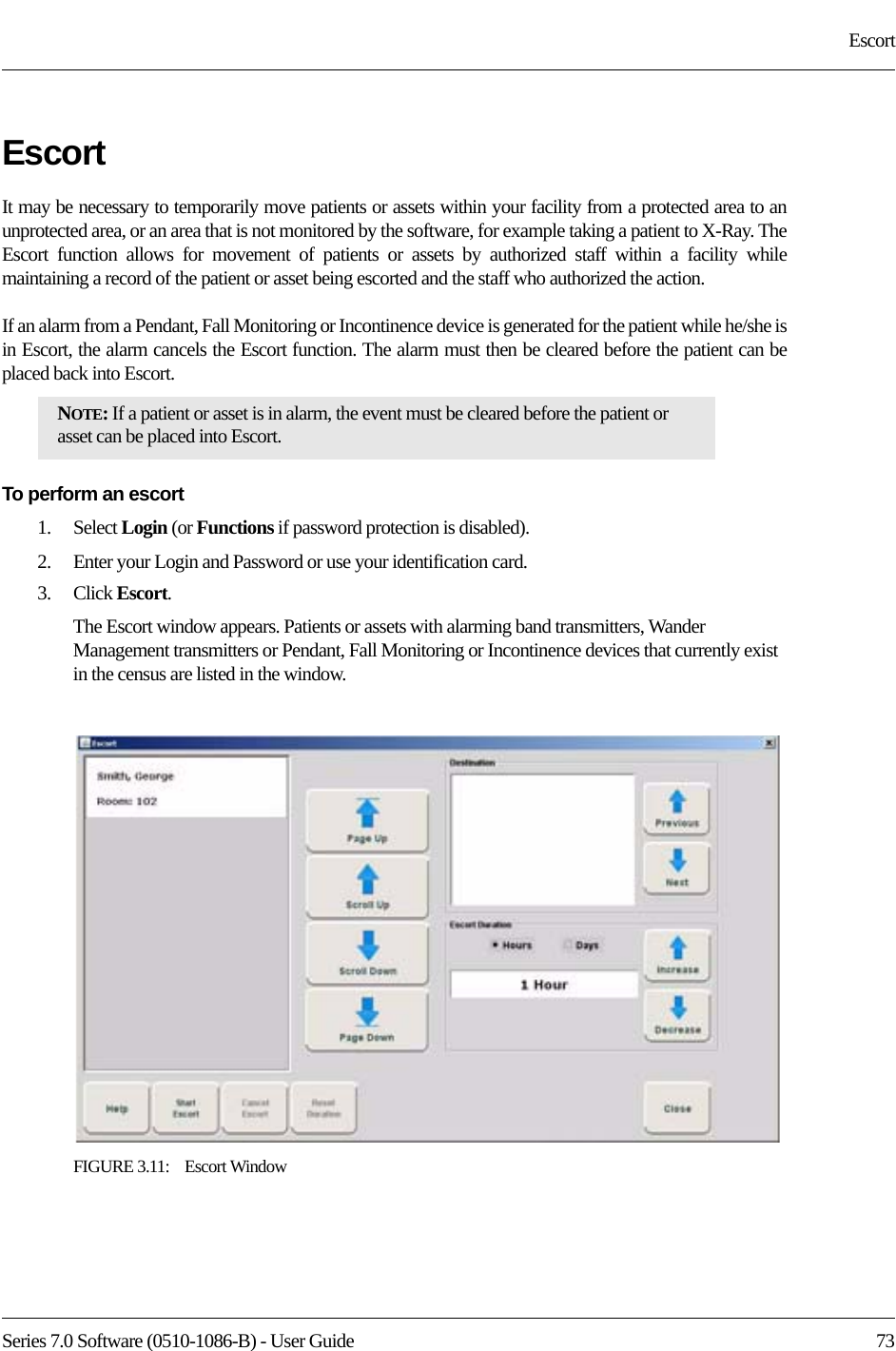
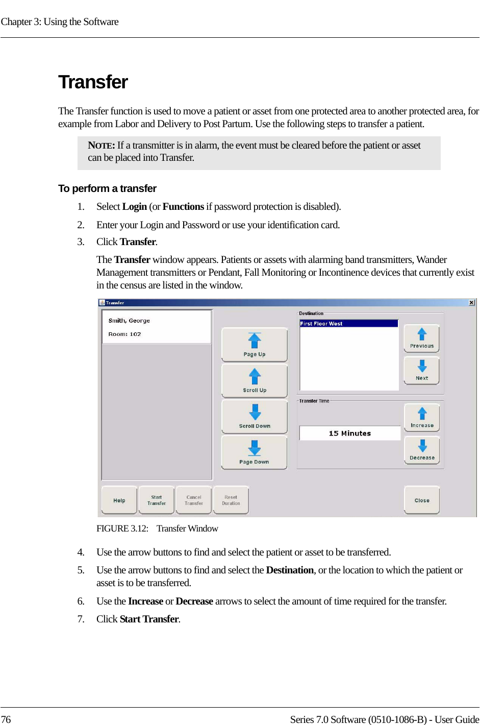
>
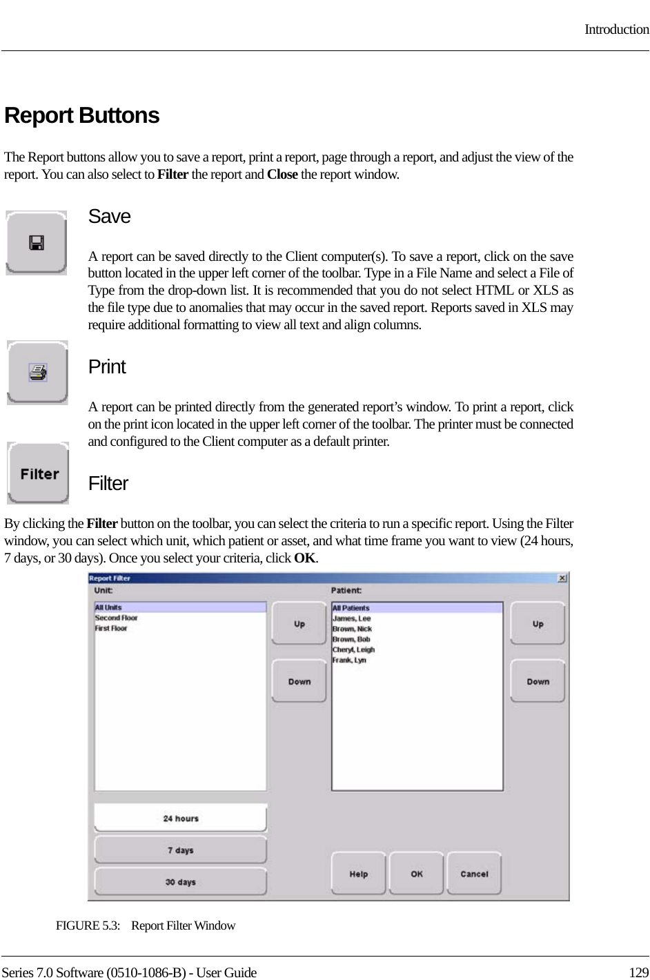
R F Technologies
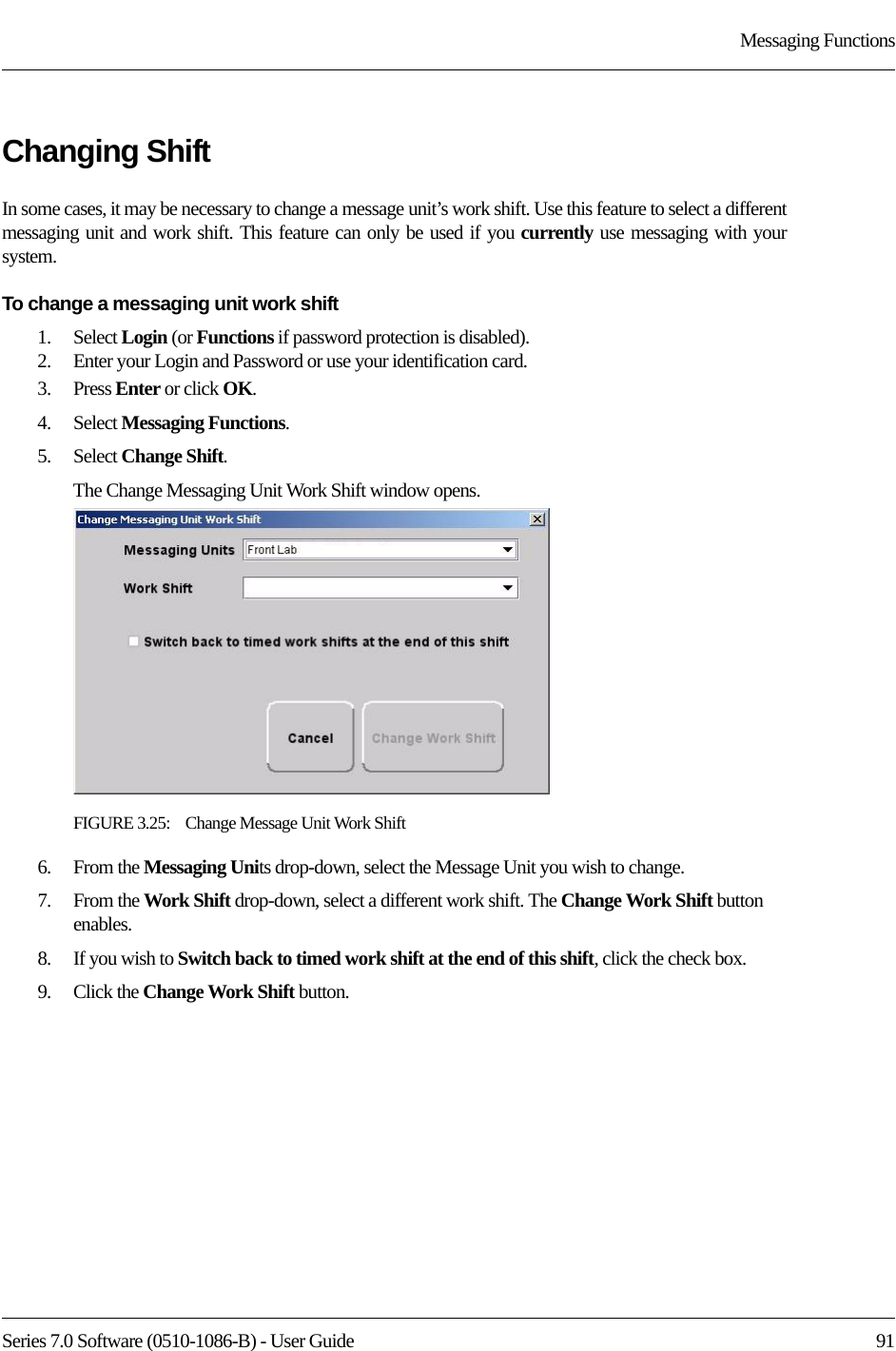
>
CBTX User Manual
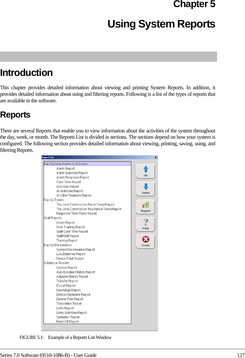
User Manual
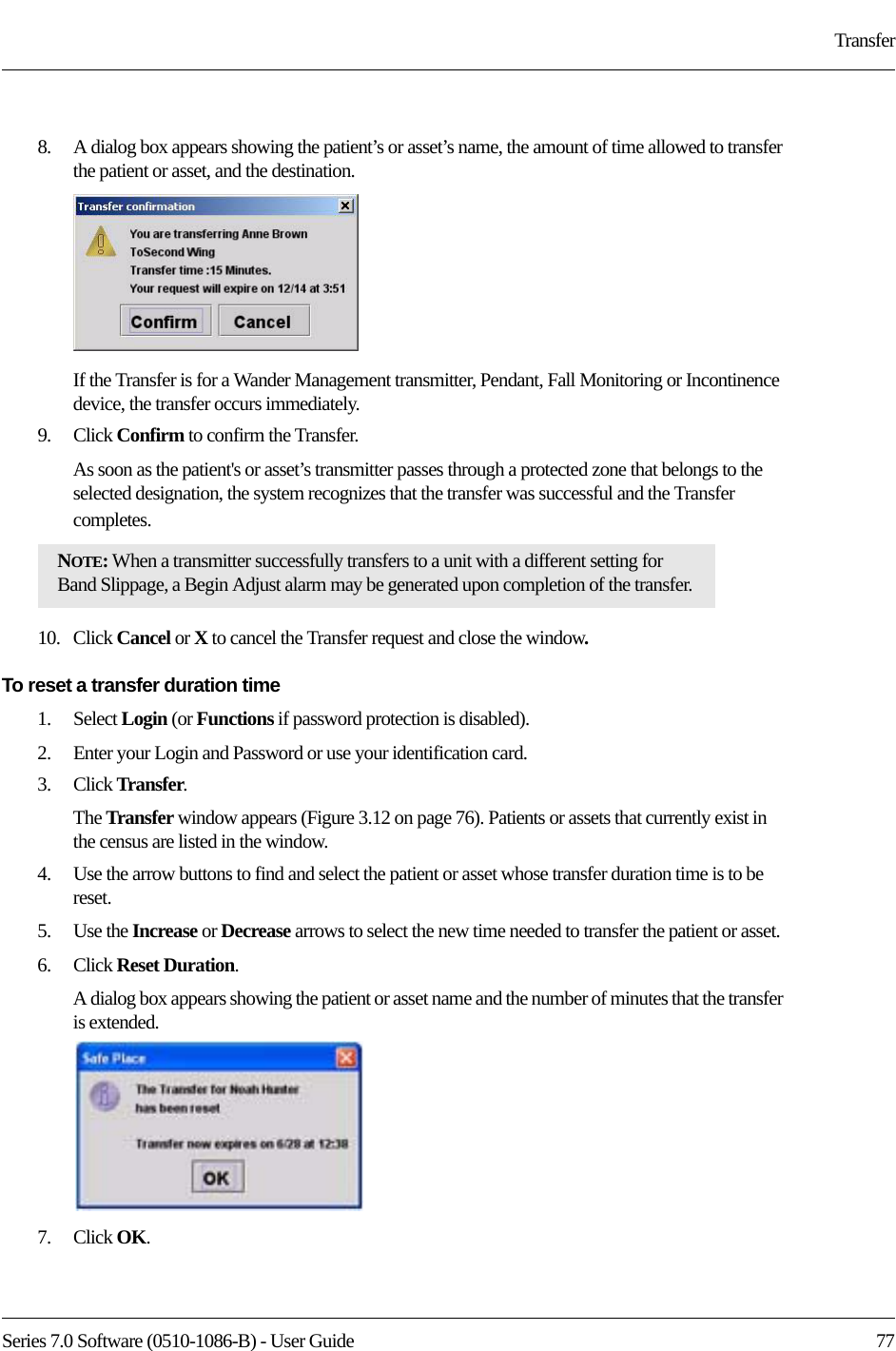
Navigation menu
Upload a User Manual
Namespaces
Wiki Guide
HTML
PDF
Info
Views
User Manual
Discussion / Help
Navigation


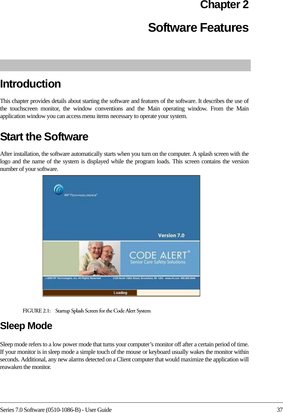
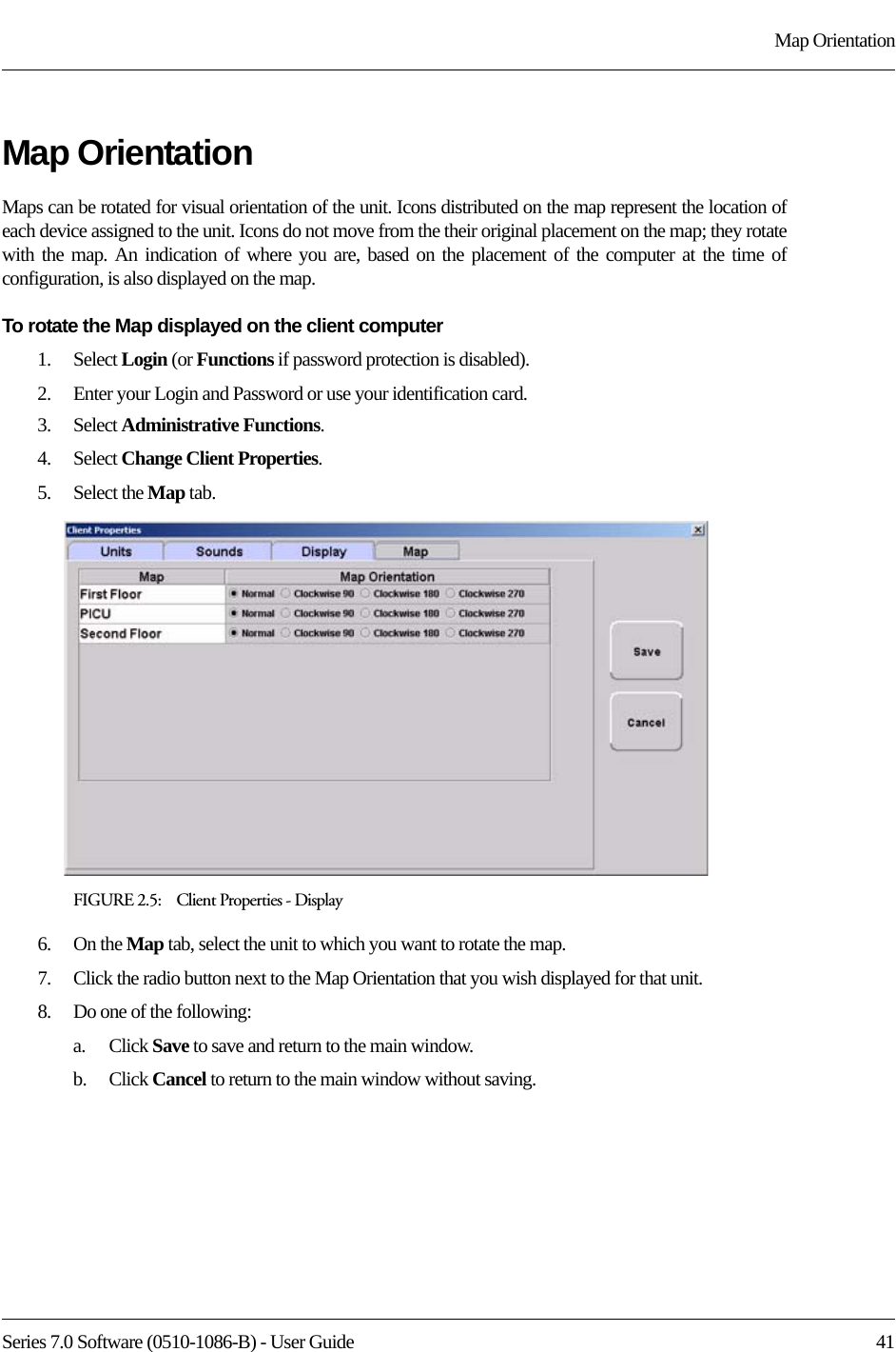
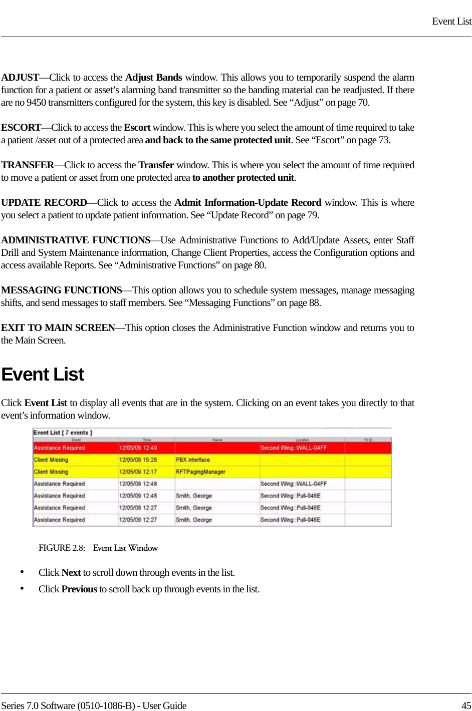
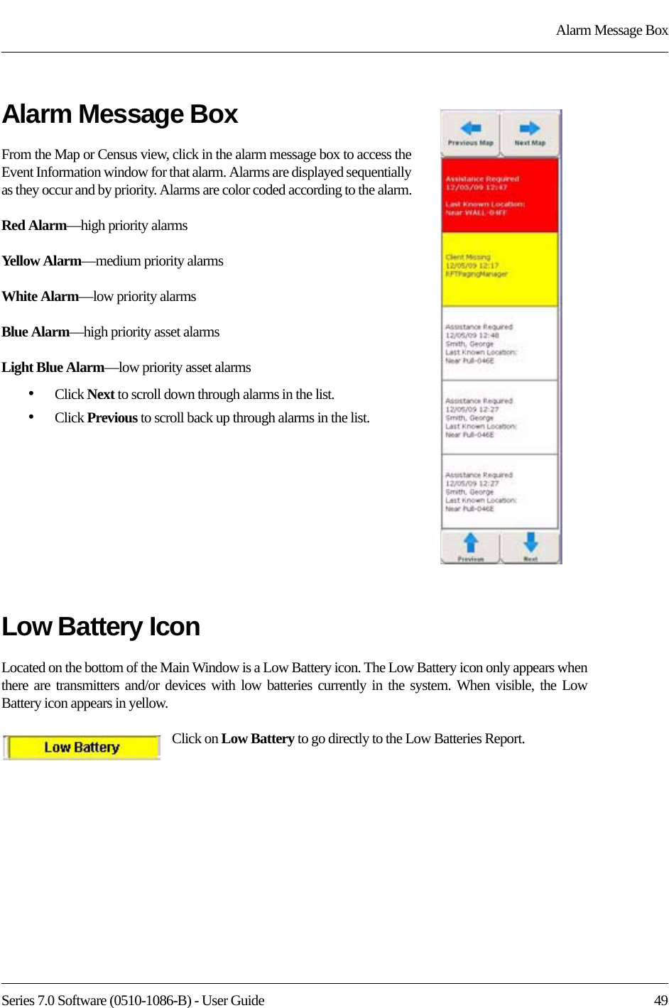

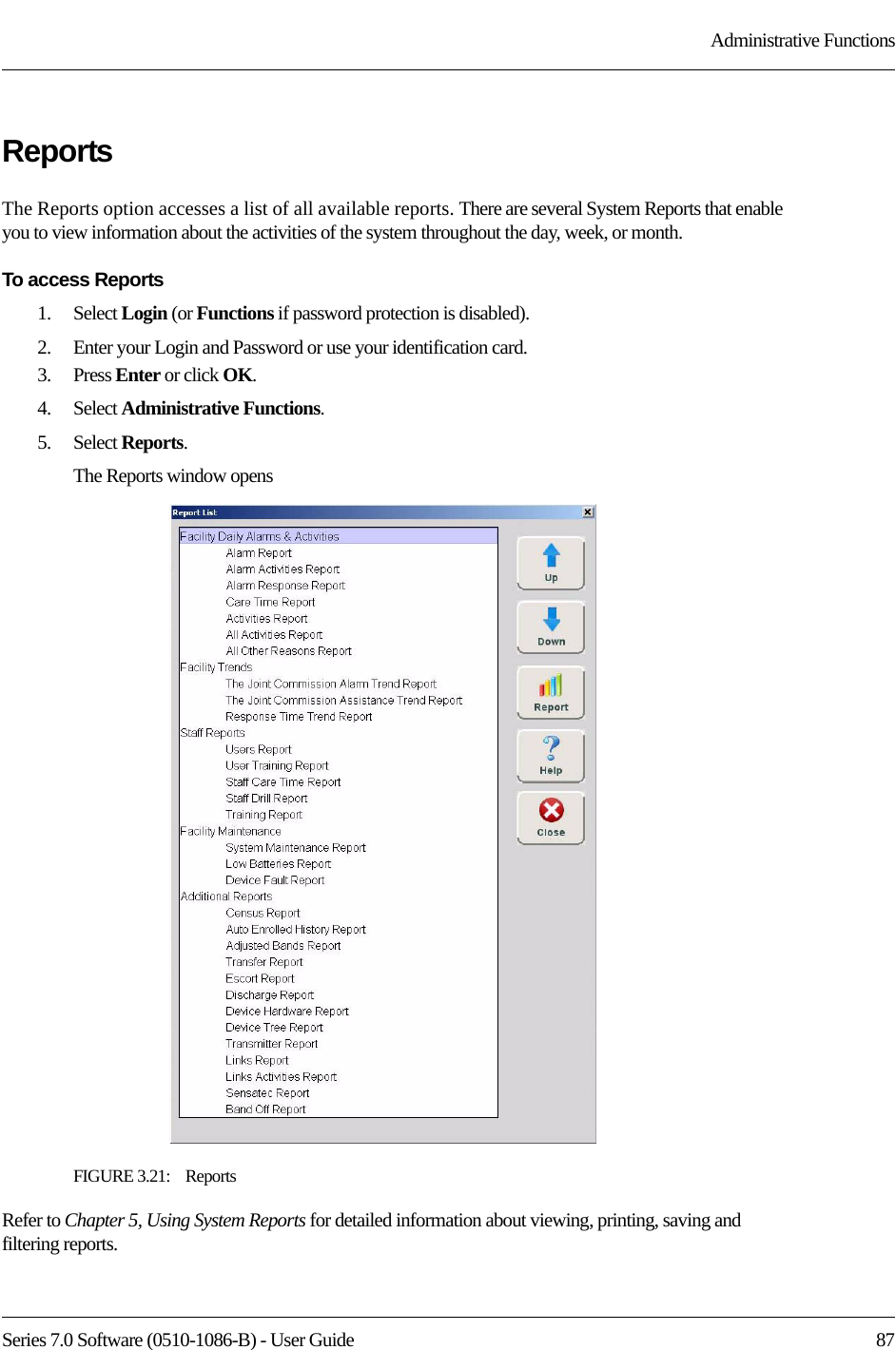
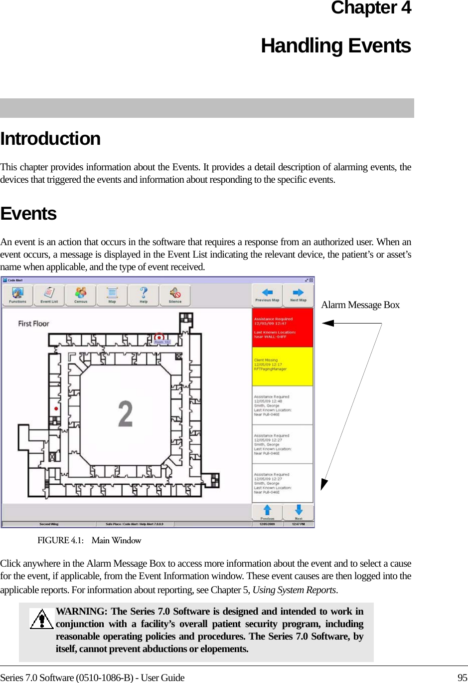
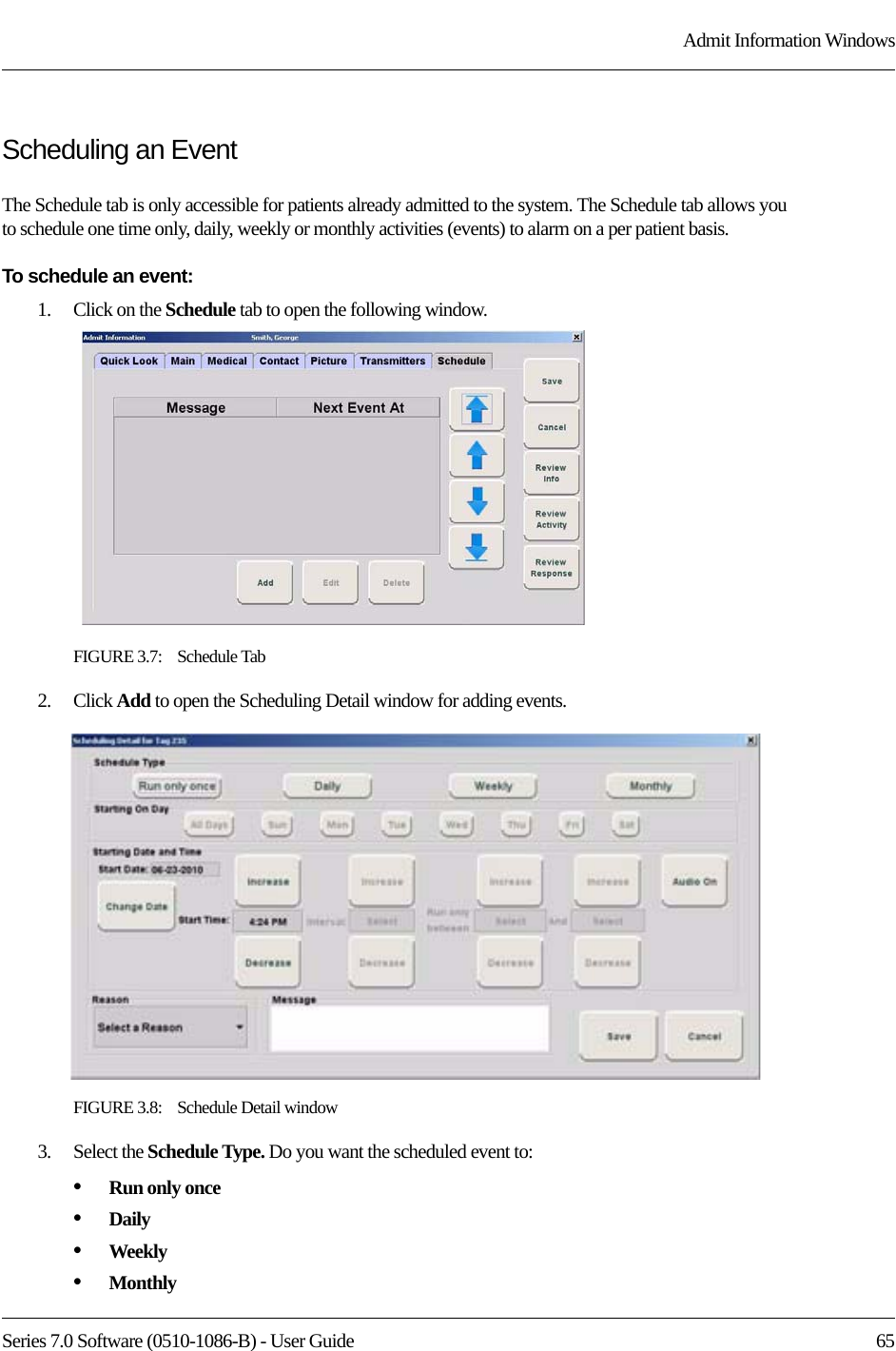
![Series 7.0 Software (0510-1086-B) - User Guide 61Admit Information WindowsMain TabThe Main information tab allows you to enter general information about the patient being admitted; the yellow fields designate required entry. Depending on your configuration, the Birth Date field may be a required entry for the Series 7.0 Software. When updating admit information for patients who were enrolled in the system prior to software version 7.0, you must enter the patient’s birth date even if that information was not previously entered. 1. Click the Main tab.2. In the First Name box, type the first name of the patient being admitted (either first or last name is required). 3. In the Last Name box, type the last name of the patient being admitted (either first or last name is required).4. Type the patient’s Address, City, State, Zip.5. In the Phone field, type the phone number of the patient.6. In the Unit field, select the unit to which the patient is currently assigned, even if the patient will not remain in that unit (required).7. In the Room field, select the patient’s room number.8. In the Birth Date field, enter the patient’s birthday (two digit month, two digit day, four digit year).9. Click Female or Male to indicate the gender of the patient.10. In the Discharge Planning Date field, enter the planned date of discharge (the appearance of this field depends on your system configuration)11. In the Training Delivered field, indicate the type of training material used by entering the date training was delivered to the patient or patient’s family.12. In the Transmitter ID field, type the 3-digit ID number printed on the transmitter to be assigned to the patient.13. Click Configure to configure the Band Off settings for the transmitter. (See “Configure Band Off” on page 62.)14. Click the Risk level for abduction or elopement associated with the patient. Choices are Low, Medium or High.NOTE: Information entered can only contain alphabetic and numeric characters, spaces, and the following special characters: ! - _ , . ; [ ]{ }( )](https://usermanual.wiki/R-F-Technologies/CBTX/User-Guide-1390342-Page-77.png)
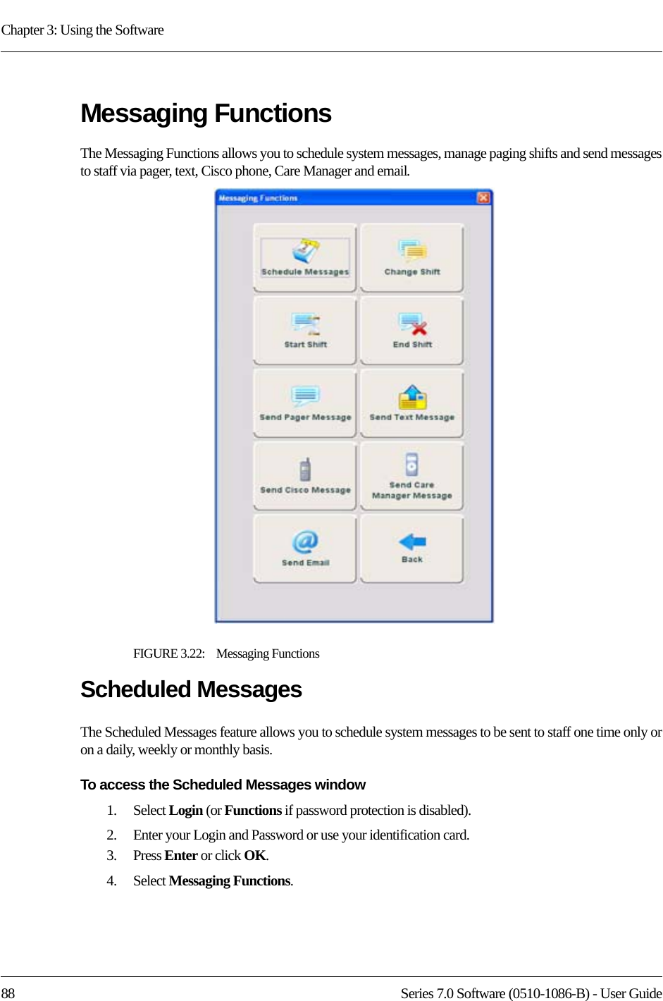
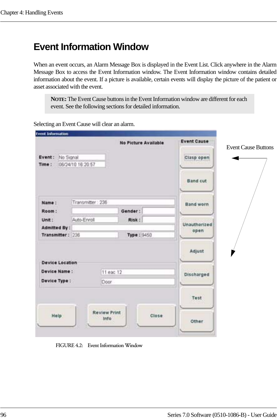
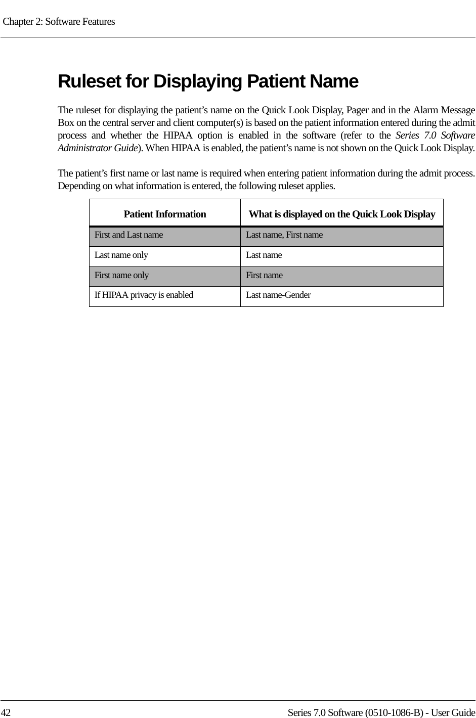
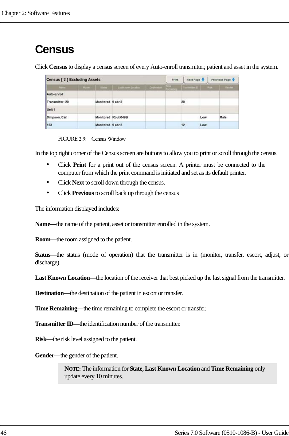
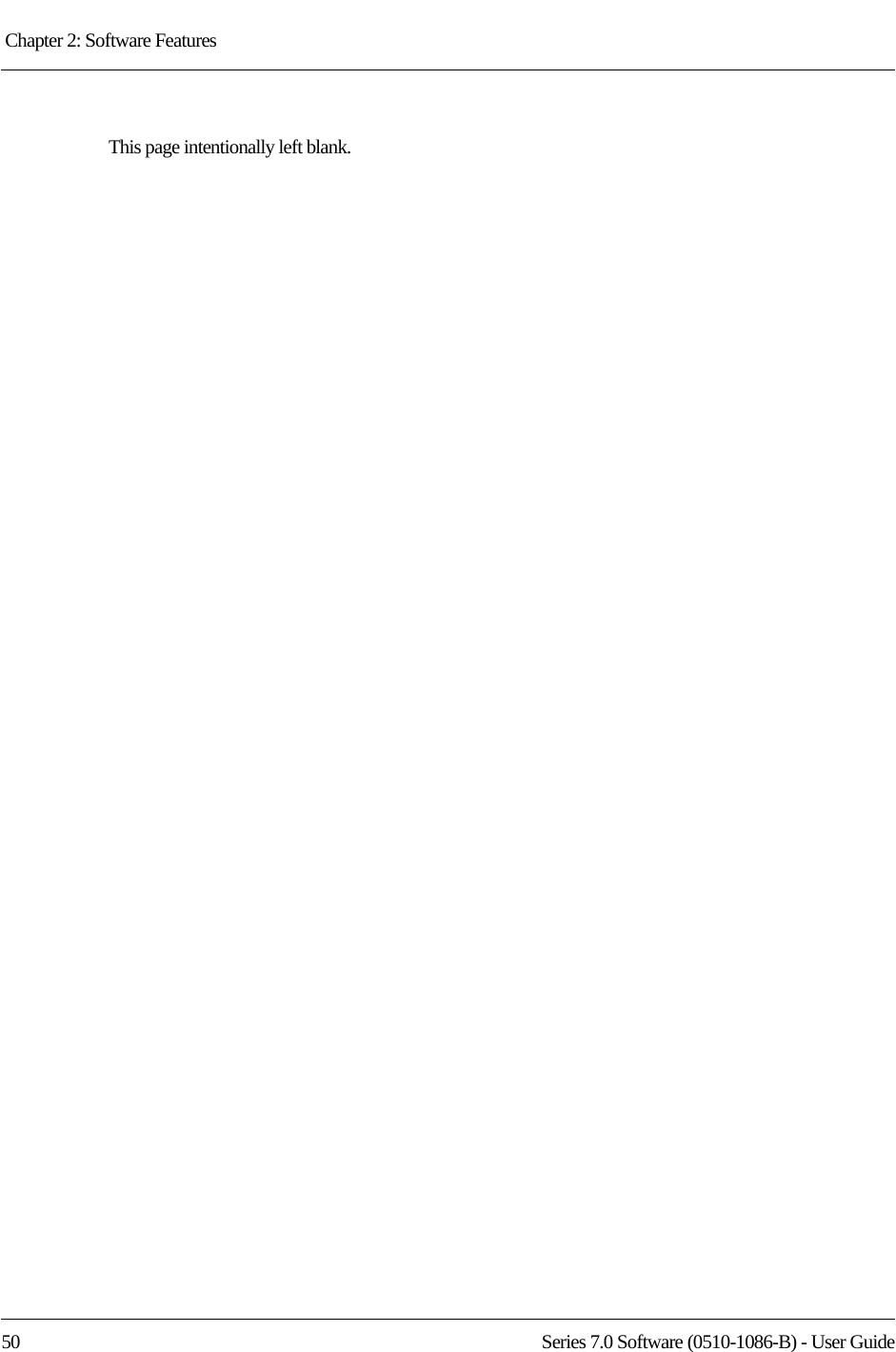
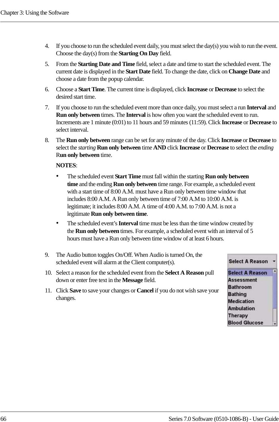
![Series 7.0 Software (0510-1086-B) - User Guide 63Admit Information WindowsMedical TabThe Medical information tab is only accessible from the Patient Admit Information window. To access the Medical Info tab, the user must be a configured into the system as a Care Provider (refer to the Series 7.0 Software Administrator Guide). The Medical Info tab allows you to enter medical information about the patient being admitted. Fields are provided here for you to enter information necessary per your facility’s policies and procedures. Contact TabThe Contact information tab allows you to enter contact information about the patient or asset being admitted.1. Click the Contact tab.2. In the Special Instructions field, type any special instructions associated with the patient or asset.3. In the Name field, type the name of the primary contact for inquires regarding the patient or asset.4. In the Phone field, type the phone number of the primary contact.5. Type the Address, City, State, Zip of the primary contact.If there is more than one contact, you can enter that information in the subsequent contact fields. Insert a PictureThe Picture tab allows you to insert a picture of the patient or asset being admitted. The patient’s picture is displayed on patient generated reports. When available, the patient’s picture also appears in the Event Information window for Cut Band, Door, and No Signal alarms as well as alarms generated from Pendant, Fall Monitoring and Incontinence devices. All of the pictures in the system are stored on the P: drive on the Server. When you need to enter a picture for a patient, go to the P: drive. 1. To insert a picture, click or press the (...Browse) button.2. Select a picture from the Browse Picture Files dialog box.NOTE: Information entered can only contain alphabetic and numeric characters, spaces, and the following special characters:! - _ , . ; [ ]{ }( )NOTE: Information entered can only contain alphabetic and numeric characters, spaces, and the following special characters: ! - _ , . ; [ ]{ }( )IMPORTANT: All pictures must be placed in the P: directory. If you are using a digital camera, removable USB drive, or any other removable media, you must first save the picture file to the P: directory before removing the media. It is the responsibility of the customer to have the system work on their domain which governs the security access to their network.](https://usermanual.wiki/R-F-Technologies/CBTX/User-Guide-1390342-Page-79.png)
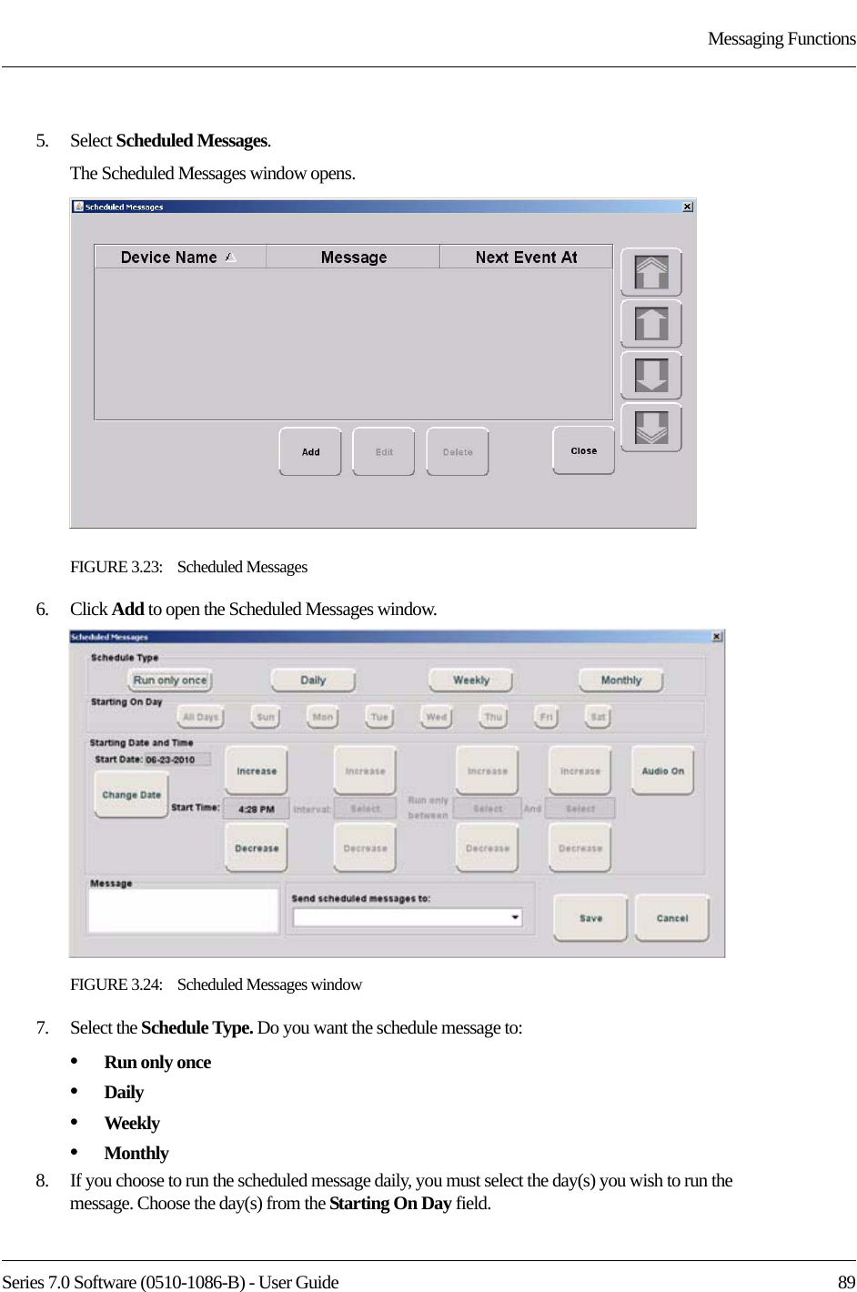
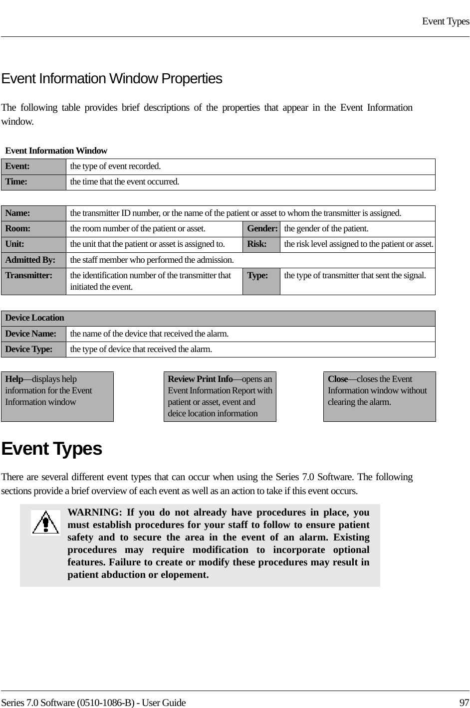
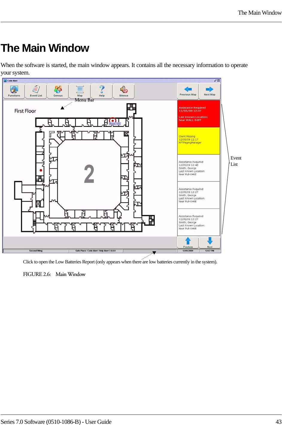
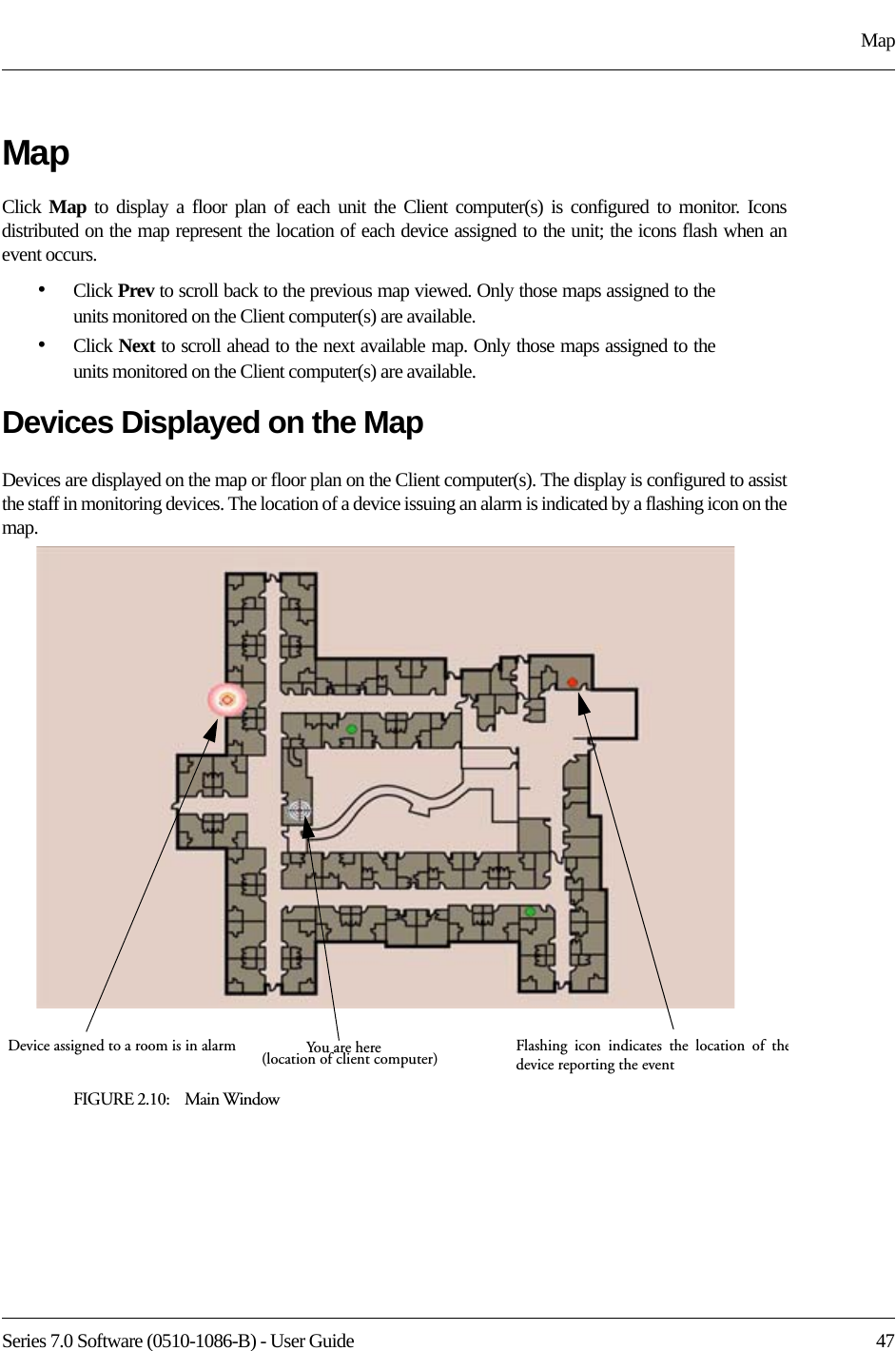
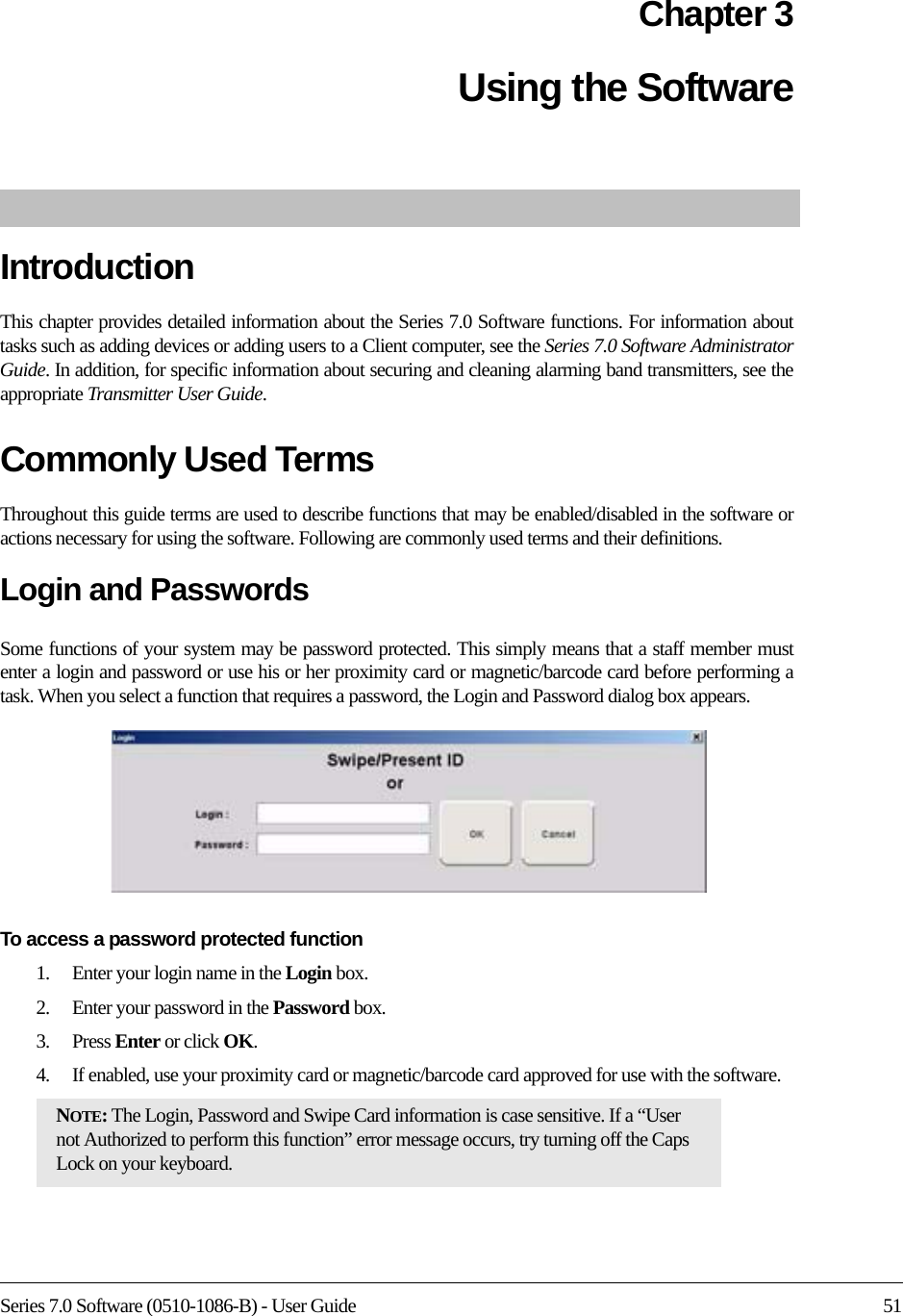
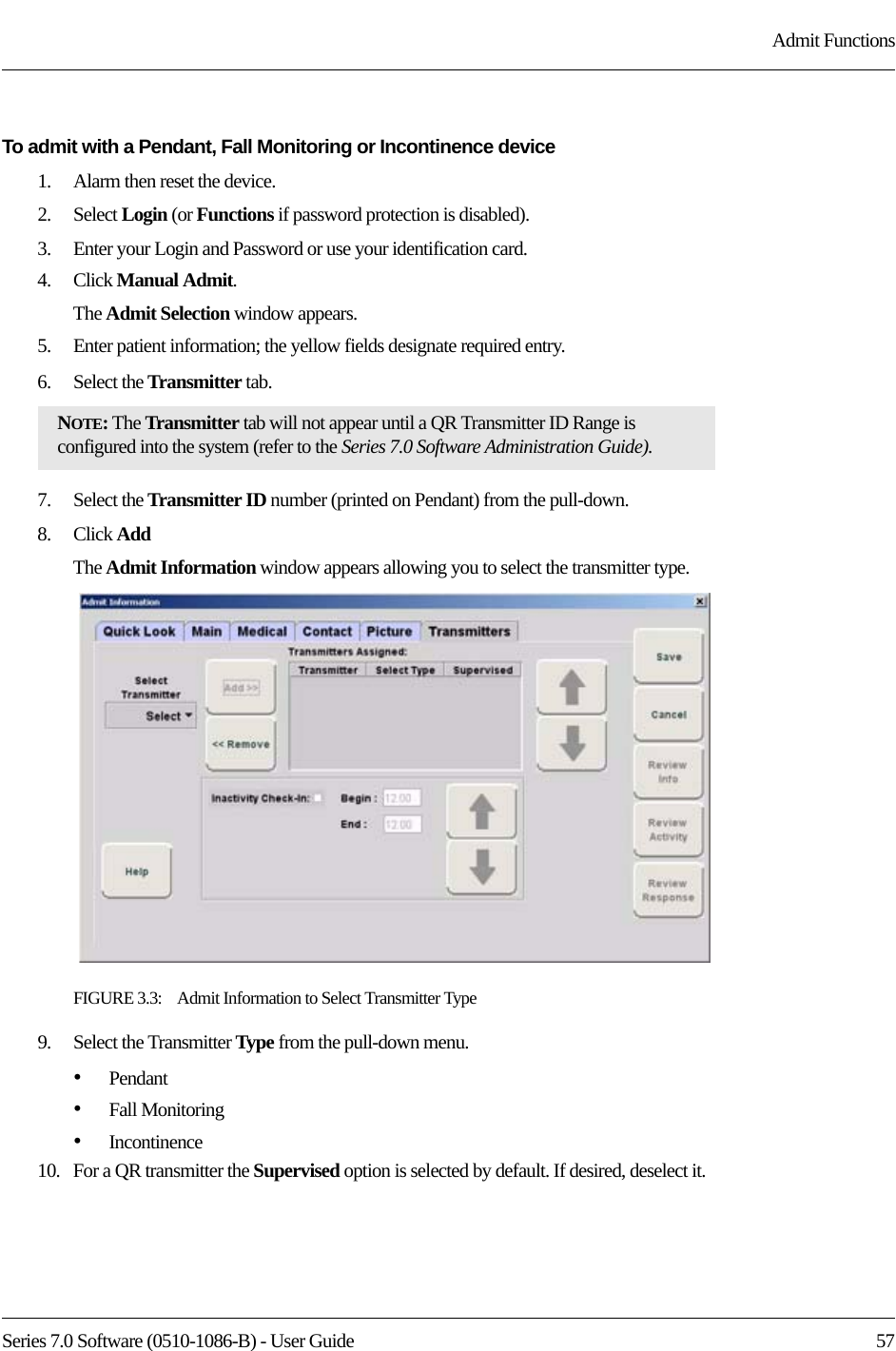
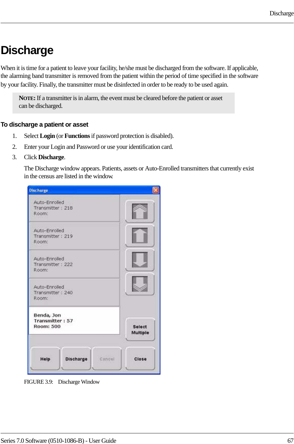
![Chapter 3: Using the Software64 Series 7.0 Software (0510-1086-B) - User GuideTo save a picture to the P: drive on the Server1. Insert the removable media (USB drive).2. On the Computer Desktop, double-click My Computer.3. Double-click the removable media. 4. Right-click the pictures on the media you want to access and select Copy.5. Double-click P:.6. Double-click Pictures.7. Double-click Patient or Asset.8. Right-click and select Paste to paste the pictures to the P: drive for access. Enter Transmitter InformationThe Transmitters tab is only accessible from the Patient Admit Information window. The Transmitter tab allows you to enter Pendant, Fall Monitoring and Incontinence transmitter information of the patient being admitted.To enter transmitter information of the patient being admitted:1. Click the Transmitters tab.2. Select the patient’s transmitter number in the Transmitter ID: field.3. Click Add.4. From the Transmitter Assigned field, select the transmitter type.5. For a QR transmitter the Supervised option is selected by default. If desired, deselect it.6. For an 9600 Series transceiver the Supervised time defaults to the unit’s Transmitter Supervise Time, set during configuration. However, you can select a different time from the drop-down list.7. If you want to enable the Inactivity Check-In feature for the transmitters, select the check box.8. Enter the Begin and the End times for the Inactivity Check-In.9. Click Save.NOTE: Information entered can only contain alphabetic and numeric characters, spaces, and the following special characters: ! - _ , . ; [ ]{ }( )](https://usermanual.wiki/R-F-Technologies/CBTX/User-Guide-1390342-Page-80.png)
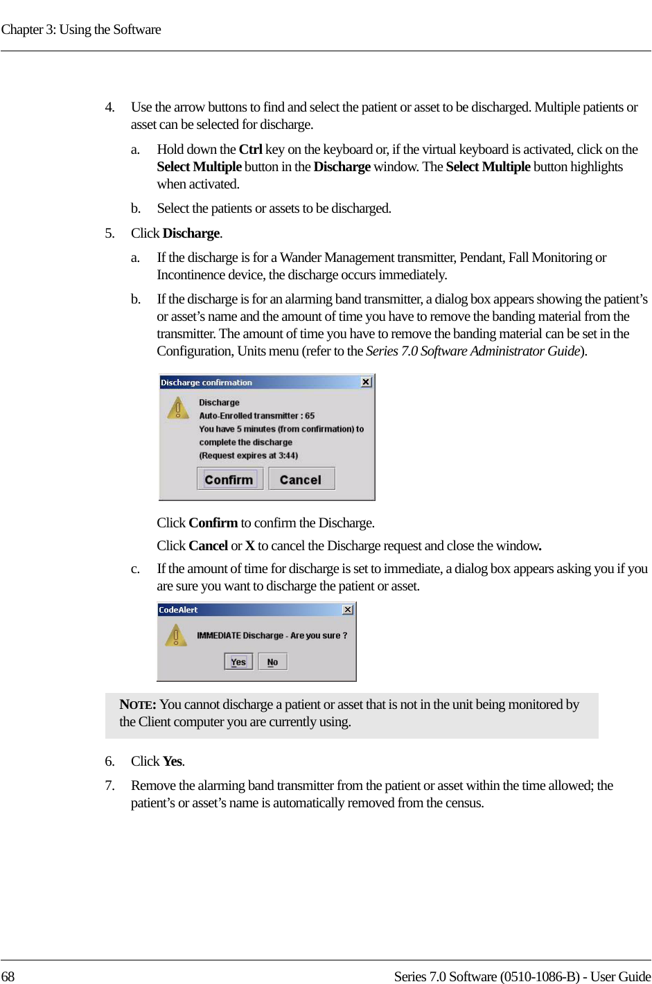
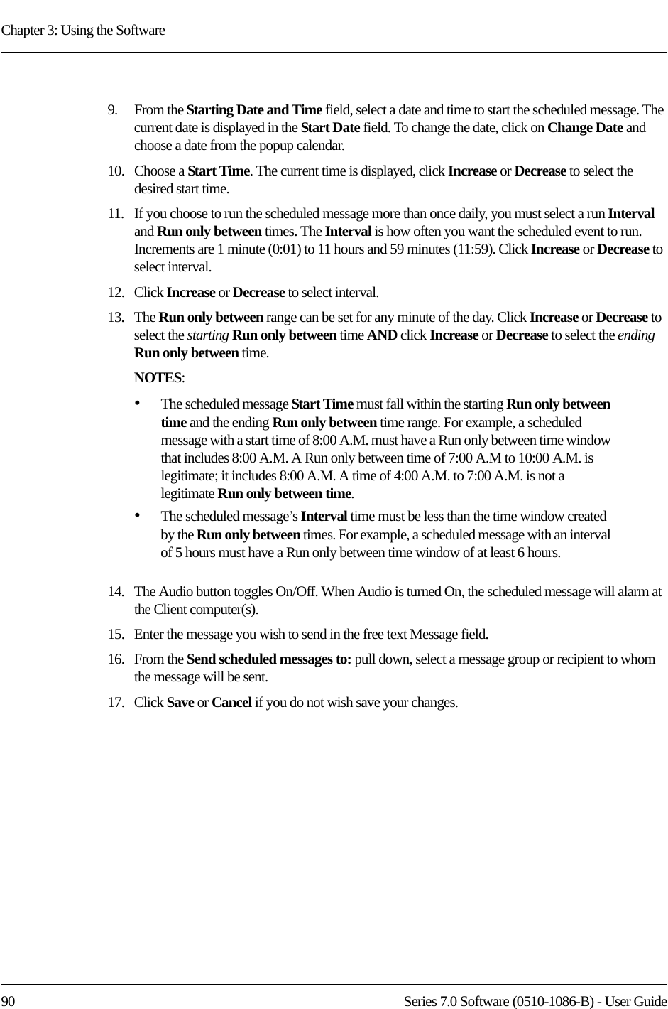
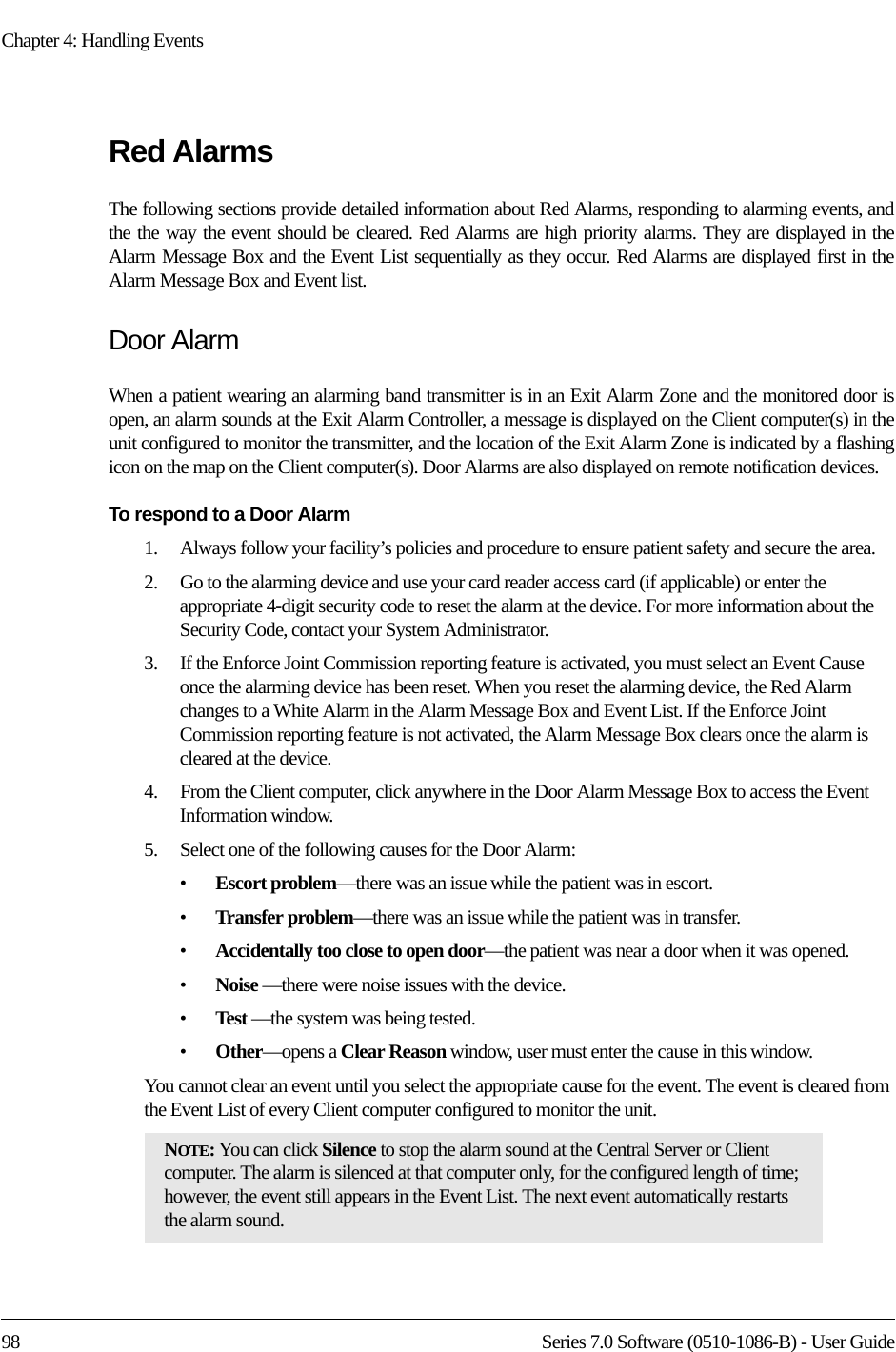
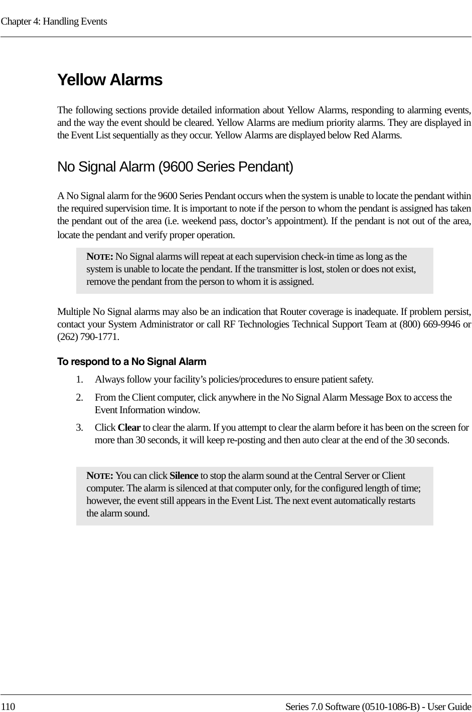
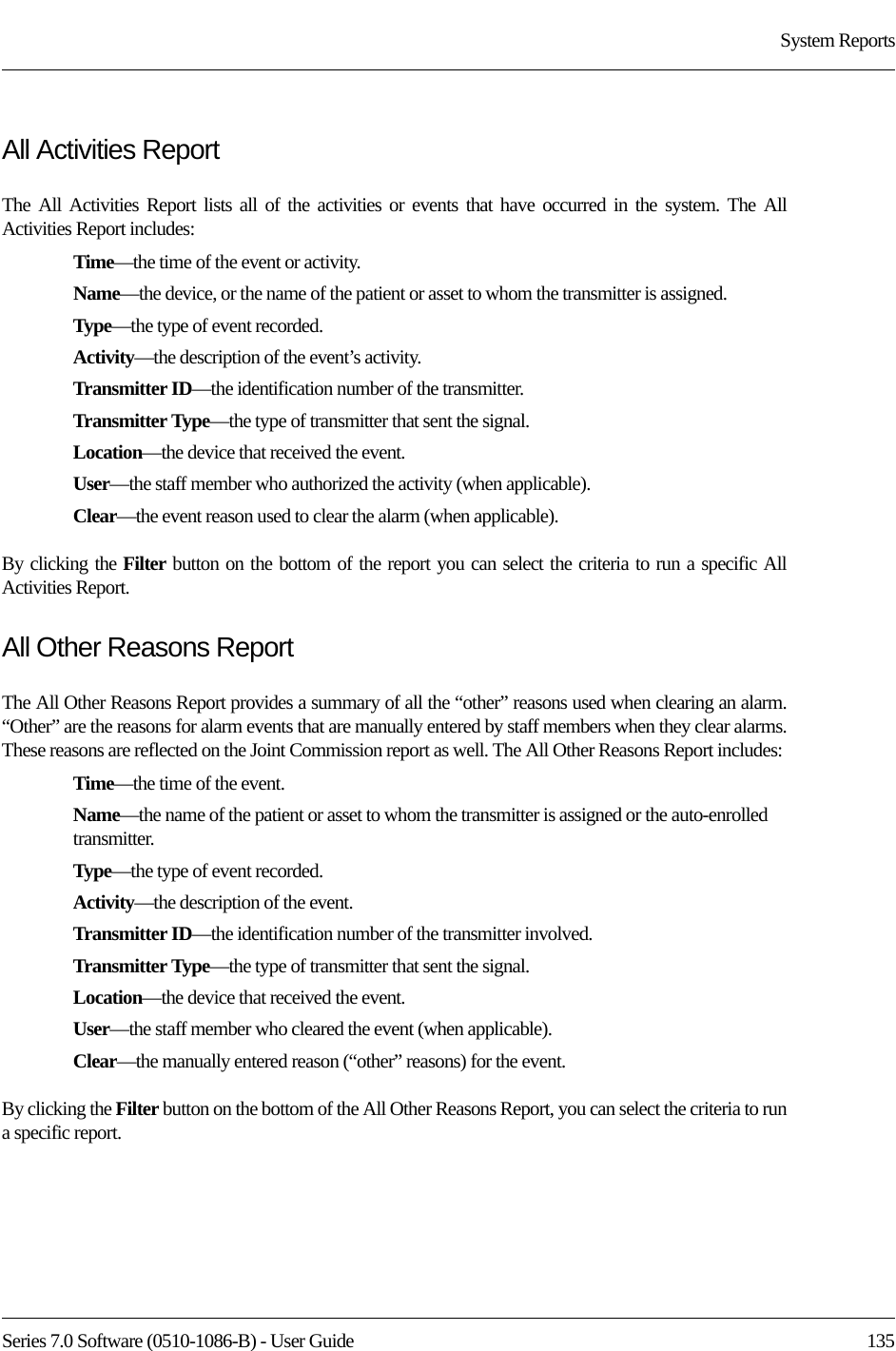
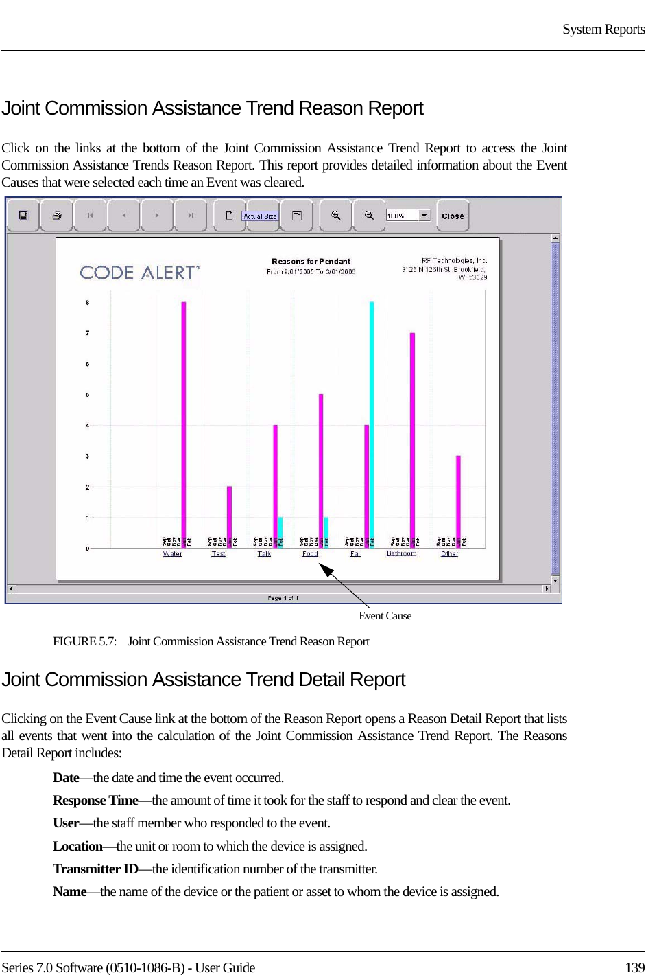
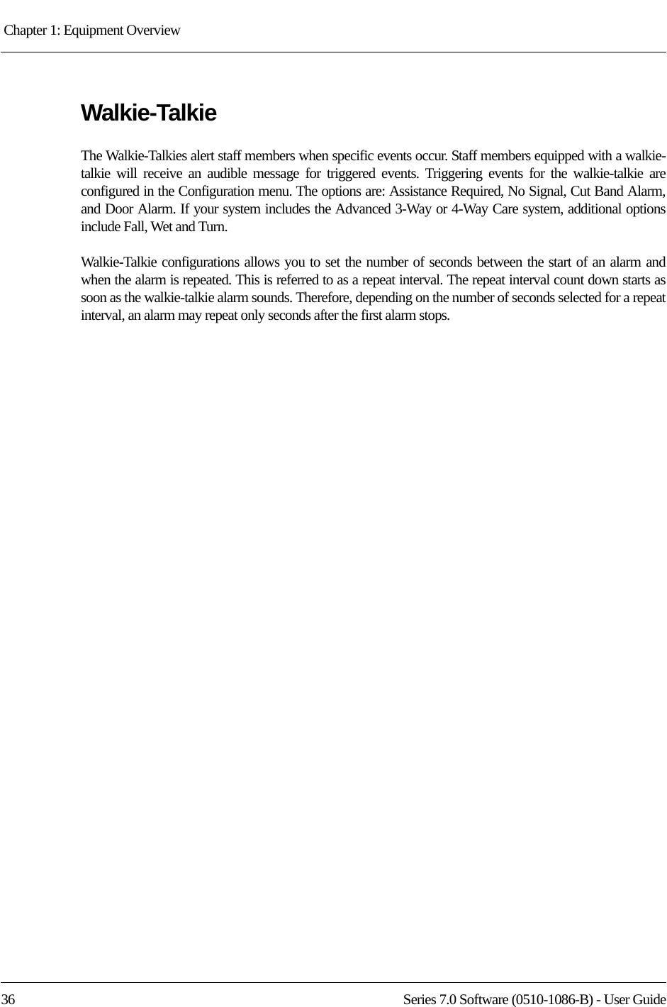
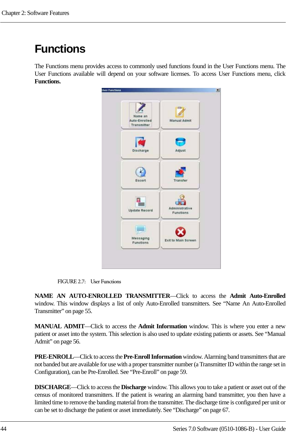
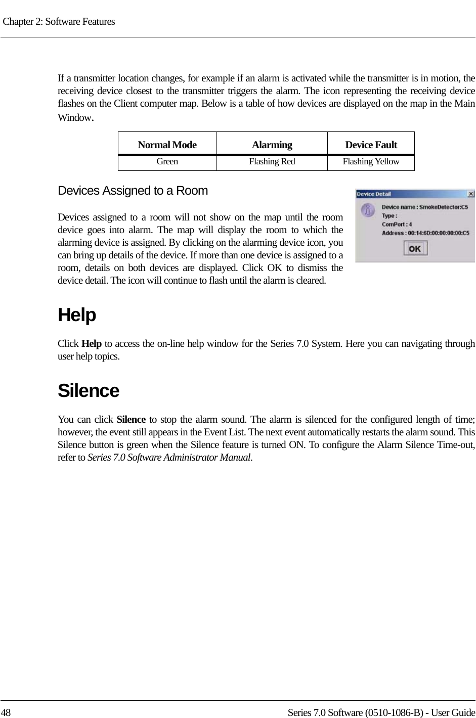
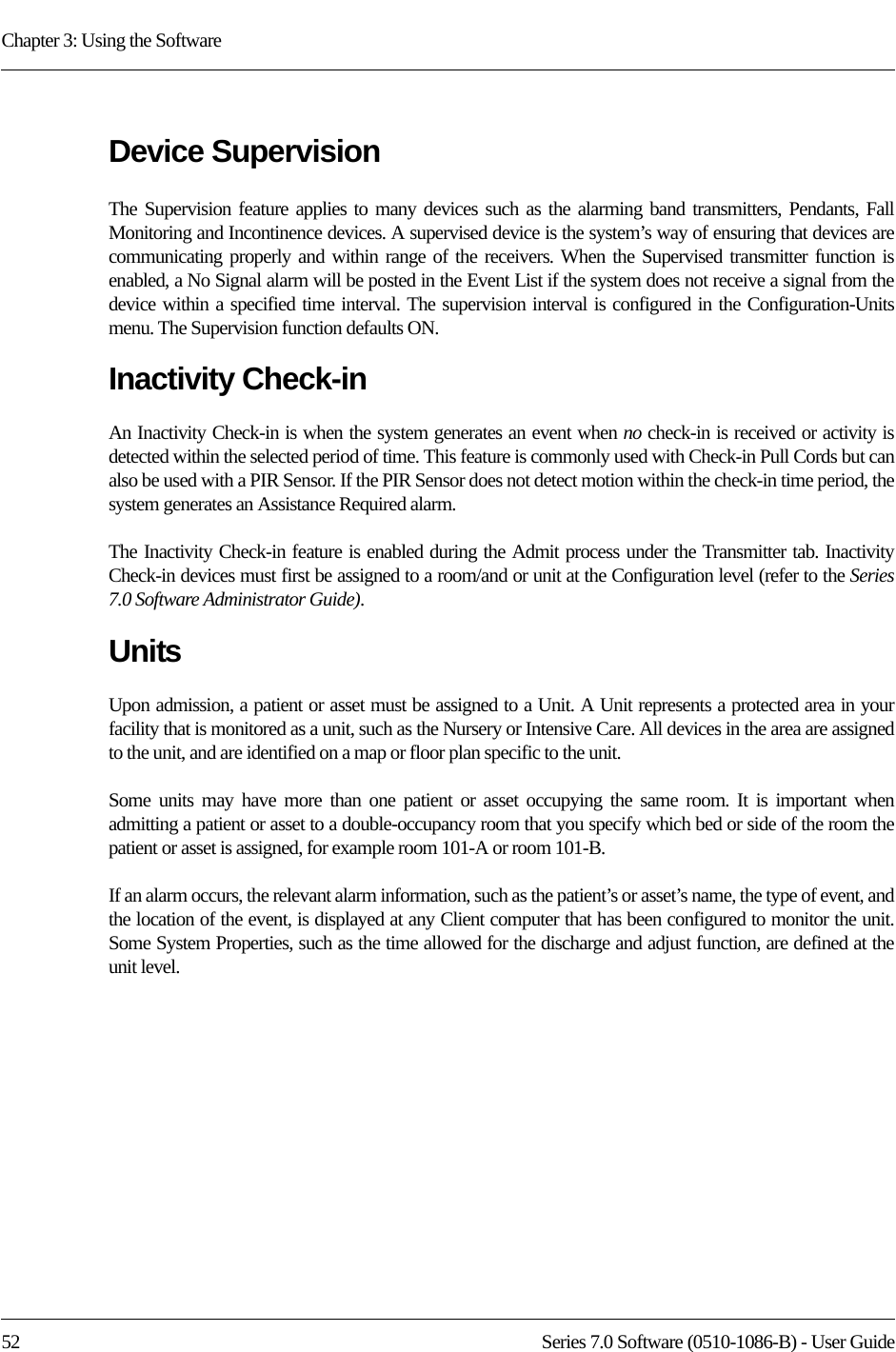
![Chapter 3: Using the Software82 Series 7.0 Software (0510-1086-B) - User GuideFIGURE 3.16: Admit Information7. Once admit information has been entered, click Save.If the admit is successful, you will get the following dialog box:8. Click OK. Asset Main Information TabThe Asset Main information tab allows you to enter identification information about the asset being admitted. The yellow fields designate required entry.1. Click Main on the toolbar.2. In the Model field, type the model or description of the asset being admitted (required). 3. In the Make field, type the manufacturer’s information of the asset being admitted.4. In the SN field, type the serial number of the asset being admitted.5. In the Transmitter ID field, type the 3-digit ID number printed on the alarming band transmitter to be assigned to the asset.6. In the Unit field, select the unit to which the asset is currently assigned, even if the asset will not remain in that unit (required).7. Click the Risk level associated with the asset. Choices are Low or High. If your facility has enabled the Lockdown on Cut Band Alarms feature, a Cut Band Alarm will trigger a Global Lockdown when a High Risk level is selected for an asset transmitter.NOTE: Information entered can only contain alphabetic and numeric characters, spaces, and the following special characters: ! - _ , . ; [ ]{ }( )](https://usermanual.wiki/R-F-Technologies/CBTX/User-Guide-1390342-Page-98.png)