R F Technologies CBTX Proximity Reader User Manual 0510 1086 B Series 7 0 Software Users Guide
R F Technologies Inc Proximity Reader 0510 1086 B Series 7 0 Software Users Guide
User Manual

3125 North 126th Street, Brookfield, WI 53005 USA
phone: 800.669.9946 web: www.rft.com
Series 7.0 Software
User Guide
PN 0510-1086-B

Series 7.0 Software
User Guide
Supports the 9450 Series Systems, Quick Response Systems,
9500 Series Wired Systems and 9600 Series Systems
PN: 0510-1086-B
Release Date: 06/29/10
Users must read this Guide before using the Product.
Copyright 2009, 2010 by RF Technologies, Inc.
All Rights Reserved. No Part of this work may be reproduced or copied in any form or by
any means without written permission from RF Technologies, Inc.

Important Warnings
It is important for your facility to implement and enforce the following WARNINGS in order to keep all equipment
functioning properly. Disregarding the information and instructions in this document is considered abnormal use and
may result in injury or system failure.
WARNING
ACCESSORIES (SUPPLIES)—To ensure patient safety and proper operation of equipment,
use only parts and accessories manufactured or recommended by RF Technologies, Inc. Parts
and accessories not manufactured or recommended by RF Technologies, Inc. may not meet the
requirements of the applicable safety and performance standards.
Failure to use the components and supplies specified by RF Technologies, Inc. may result in
equipment and/or system failure.
WARNING
EXPLOSION HAZARD—These devices should not be used in the presence of flammable gas
mixtures. It should also not be used in oxygen enriched atmospheres.
WARNING
INSTALLATION AND CONFIGURATION—It is the responsibility of the facility to follow the
installation instructions carefully, as outlined in the applicable system guides, and to use the components
and supplies specified by RF Technologies, Inc. for all installations.
Failure to use the components and supplies specified by RF Technologies, Inc. may result
in equipment and/or system failure.
WARNING
INSTRUCTIONS FOR SET UP AND USE—It is the responsibility of the facility to follow the
instructions for set up and use carefully, as outlined in this manual, and to use the components and
supplies specified by RF Technologies, Inc. for set up and use. Do not attempt to use extension cords or
other equipment not supplied by RF Technologies, Inc.
Failure to use the components and supplies specified by RF Technologies, Inc. may result in
equipment and/or system failure.
WARNING
PATIENT GENERATED ALARMS—Do not rely exclusively on patient generated alarms for
patient care and safety. The alarm function of equipment in the possession of patients must be
verified periodically and regular patient surveillance is recommended.

WARNING
PATIENT MONITORING—The most reliable method of patient monitoring combines close
personal surveillance with correct operation of monitoring equipment. It is the responsibility of
the facility to periodically check on patients in possession of RF Technologies, Inc.'s
equipment (i.e. Pendants, Pull Cords, Control Units) to mitigate risk of inappropriate use of
equipment or strangulation and stumbling hazards from cables and cords
WARNING
PRODUCT WARRANTIES—Failure to follow the Warnings and Cautions in this guide voids
any and all Product Warranties
WARNING
STATIC DISCHARGE—Do not touch the conductor portion of any conductor or port.
Damage to the device may result.
WARNING
STRANGULATIONS AND TRIPPING HAZARD—Due to the possibility of strangulation, all cables
and cords should be routed away from the patient’s throat. Cables and cords must be routed in a way to
prevent tripping hazards.
WARNING
SYSTEM INSPECTION—It is the responsibility of the facility to establish and facilitate a
regular inspection schedule for your system. RF Technologies, Inc. recommend quarterly
inspections of your system for safety and performance by a qualified RF Technologies, Inc.
representative.
To arrange for a quarterly inspection by RF Technologies, Inc., call our Technical Support
Department at (800)-669-9946 or (262) 790-1771.
Failure to provide regular inspection of these products may result in equipment and/or system
failure.
WARNING
SYSTEM MAINTENANCE AND TESTING—It is the responsibility of the facility to
establish and facilitate a regular maintenance schedule for your system, as outlined in the
applicable system guides. This includes regular inspection, testing, and cleaning. RF
Technologies, Inc. recommend monthly maintenance and testing of your system. It is also
recommended that your facility keep records of maintenance and test completions.
Failure to provide regular maintenance and testing of these products may result in equipment
and/or system failure.
Bio-Incompatibility Notice
Do not use Pendants with people that have sensitivities or allergies to device materials. The device materials include
Acrylonitrile butadiene styrene (ABS), Silicon Rubber and Neoprene
WARNING
SYSTEM WIRING—All permanent supply connections must be done in accordance with
National Electric Code, NFPA 70.
WARNING
USER TRAINING—Only users who have received adequate training on the use of the system, as
outlined in this manual, should use the system. It is the responsibility of the facility to ensure all users
have been trained.
Failure to adequately train employees may cause system failure due to user error. In addition,
incorrect use of the equipment may also result in system failure.
WARNING
WORN OR DAMAGED PARTS—If the control unit pads or cables are worn or damaged, you must
have the product serviced. For more information, see the section entitled “Service and Return.”
WARNING
All RF Technologies transmitters, pendants and banding material “PRODUCT” have been
determined to be MR Unsafe as defined by ASTM F 2503-05. Use of “PRODUCT” in a
Magnetic Resonance Imaging system will cause injury to patients and staff, MR system
malfunction or “PRODUCT” malfunction. Do not bring “PRODUCT” into the MR system
area and follow your facilities policies to classify and label “PRODUCT” as MR Unsafe.
CAUTION
DISPOSAL—At the end of their service life the products described in this manual, as well as
accessories (i.e. lithium batteries, banding material, disposable pads, etc.), must be disposed of
in compliance with all applicable federal, state and local guidelines regulating the disposal of
products containing potential environmental contaminants. Dispose of the packaging material
by observing the applicable waste control regulations.
Compliance
Federal Communication Commission (FCC)
Compliance
This device complies with Part 15 of the FCC Rules. Operation is subject to the following two conditions: (1) this device
may not cause harmful interference, and (2) this device must accept any interference received, including interference that
may cause undesired operation of the device.
This equipment generates, uses, and can radiate radio frequency energy and, if not installed and used in accordance with
the instruction manual, may cause harmful interference to radio communications. Operation of this equipment in a
residential area is likely to cause harmful interference in which case the user will be required to correct the interference
at his own expense. Changes or modifications not expressly approved by the party responsible for compliance voids the
user’s authority to operate the equipment.
FCC and IC Radiation Exposure Statement for Mobile
Devices
(For the Pull Cord model 0800-0285 and model 0800-0317; Universal Transceiver model 0800-0301, which covers part
numbers 0800-0303 and 0800-0304; Extended Range Universal Transceiver model 0800-0388, which covers part
numbers 0800-0389 and 0800-0390; Extended Range Router model 0800-0351 and model 0800-0354; Router model
0800-0364; Asset Transceivers model 0800-0286 and model 0800-0302 and Motion Control Unit model 0800-0318)
This equipment complies with FCC and IC radiation exposure limits set forth for an uncontrolled environment. This
equipment should be installed and operated with minimum distance 20cm between the radiator and your body. This
transceiver must not be co-located or operating in conjunction with any other antenna or transceiver.
FCC and IC Radiation Exposure Statement for Portable
Devices
(For the Pendant Transceivers model 0800-0288 and model 0800-0349; Call Pendant model 0800-0375; and Care
Manager model 9600-0500)
This equipment complies with FCC and IC radiation exposure limits set forth for an uncontrolled environment. This
equipment is in direct contact with the body of the user under normal operating conditions. This transceiver must not be
co-located or operating in conjunction with any other antenna or transceiver.
Industry Canada Compliance
Changes or modifications not expressly approved by RF Technologies could void the user’s authority to operate the
equipment. The Term “IC” before the radio certification number only signifies that Industry Canada technical
specifications were met.
Operation is subject to the following two conditions: (1) this device may not cause harmful interference, and (2) this
device must accept any interference received, including interference that may cause undesired operation of the device.
This device has been designed to operate with the antennas listed below, and having a maximum gain of 3dBi. Antennas
not included in this list or having a gain greater than 3dBi are strictly prohibited for use with this device. The required
antenna impedance is 50 ohms. Acceptable antennas are PCB antennas in all cases of the Router which uses a 2.4 GHz 1/
2 wave RP-SMA.
To reduce potential radio interference to other users, the antenna type and its gain should be so chosen that the equivalent
isotropically radiated power (e.i.r.p.) is not more than that permitted for successful communication.

Series 7.0 Software (0510-1086-B) - User Guide i
Contents
Preface . . . . . . . . . . . . . . . . . . . . . . . . . . . . . . . . . . . . . . . . . 1
Overview . . . . . . . . . . . . . . . . . . . . . . . . . . . . . . . . . . . . . . . . . . . . . . . . . . . . . 1
9450 System . . . . . . . . . . . . . . . . . . . . . . . . . . . . . . . . . . . . . . . . . . . . . . . . . . . 1
Quick Response (QR) Wired System . . . . . . . . . . . . . . . . . . . . . . . . . . . . . . 2
9500 Series Wired Call System . . . . . . . . . . . . . . . . . . . . . . . . . . . . . . . . . . . . . .2
9600 Series Wireless Call System . . . . . . . . . . . . . . . . . . . . . . . . . . . . . . . . . 2
Intended Audience . . . . . . . . . . . . . . . . . . . . . . . . . . . . . . . . . . . . . . . . . . . . . 3
Additional Detailed Documentation . . . . . . . . . . . . . . . . . . . . . . . . . . . . . . . 3
Contact Information. . . . . . . . . . . . . . . . . . . . . . . . . . . . . . . . . . . . . . . . . . . . 3
Product Warranty. . . . . . . . . . . . . . . . . . . . . . . . . . . . . . . . . . . . . . . . . . . . . . 3
Chapter 1
Equipment Overview . . . . . . . . . . . . . . . . . . . . . . . . . . . . . 5
Introduction. . . . . . . . . . . . . . . . . . . . . . . . . . . . . . . . . . . . . . . . . . . . . . . . . . . 5
Central Server and Client Computers . . . . . . . . . . . . . . . . . . . . . . . . . . . . . 5
Quick Look Display . . . . . . . . . . . . . . . . . . . . . . . . . . . . . . . . . . . . . . . . . . . . 5
9450 System . . . . . . . . . . . . . . . . . . . . . . . . . . . . . . . . . . . . . . . . . . . . . . . . . . . 6
Staff Alert Panel . . . . . . . . . . . . . . . . . . . . . . . . . . . . . . . . . . . . . . . . . . . . . . . . .6
Exit Alarm Controller. . . . . . . . . . . . . . . . . . . . . . . . . . . . . . . . . . . . . . . . . . . . .7
Card Reader Access Device. . . . . . . . . . . . . . . . . . . . . . . . . . . . . . . . . . . . . . . . . . . . . 7
The Exit Alarm Zone . . . . . . . . . . . . . . . . . . . . . . . . . . . . . . . . . . . . . . . . . . . . . . . . . . 7
Exit Alarm Receiver . . . . . . . . . . . . . . . . . . . . . . . . . . . . . . . . . . . . . . . . . . . . . .8
Magnetic Reed Switch. . . . . . . . . . . . . . . . . . . . . . . . . . . . . . . . . . . . . . . . . . . . .8
CodeLock Electromagnetic Lock. . . . . . . . . . . . . . . . . . . . . . . . . . . . . . . . . . . .8
Alarming Band Receivers . . . . . . . . . . . . . . . . . . . . . . . . . . . . . . . . . . . . . . . . . .9
Alarming Band Zone . . . . . . . . . . . . . . . . . . . . . . . . . . . . . . . . . . . . . . . . . . . . . . . . . . 9
Alarming Band Transmitters . . . . . . . . . . . . . . . . . . . . . . . . . . . . . . . . . . . . . . .9
Patient and Infant Transmitters . . . . . . . . . . . . . . . . . . . . . . . . . . . . . . . . . . . . . . . . . . 9
Smart Sense™ Infant Transmitter and Banding Material . . . . . . . . . . . . . . . . . . . . . 10
Mother Transmitter . . . . . . . . . . . . . . . . . . . . . . . . . . . . . . . . . . . . . . . . . . . . . . . . . . 11
Wander Management Transmitter . . . . . . . . . . . . . . . . . . . . . . . . . . . . . . . . . . . . . . . 12
CodeWatch Transmitter . . . . . . . . . . . . . . . . . . . . . . . . . . . . . . . . . . . . . . . . . . . . . . . 12

Contents
ii Series 7.0 Software (0510-1086-B) - User Guide
Quick Response System . . . . . . . . . . . . . . . . . . . . . . . . . . . . . . . . . . . . . . . . 13
Wireless Receiver . . . . . . . . . . . . . . . . . . . . . . . . . . . . . . . . . . . . . . . . . . . . . . .13
Repeater. . . . . . . . . . . . . . . . . . . . . . . . . . . . . . . . . . . . . . . . . . . . . . . . . . . . . . .14
Locator . . . . . . . . . . . . . . . . . . . . . . . . . . . . . . . . . . . . . . . . . . . . . . . . . . . . . . .14
Paging Base . . . . . . . . . . . . . . . . . . . . . . . . . . . . . . . . . . . . . . . . . . . . . . . . . . . .14
Back-Up Interface. . . . . . . . . . . . . . . . . . . . . . . . . . . . . . . . . . . . . . . . . . . . . . .14
Pendant Transmitter . . . . . . . . . . . . . . . . . . . . . . . . . . . . . . . . . . . . . . . . . . . . .15
Wall Mount Transmitter. . . . . . . . . . . . . . . . . . . . . . . . . . . . . . . . . . . . . . . . . .15
Pull Cord . . . . . . . . . . . . . . . . . . . . . . . . . . . . . . . . . . . . . . . . . . . . . . . . . . . . . .15
Check-in Pull Cord . . . . . . . . . . . . . . . . . . . . . . . . . . . . . . . . . . . . . . . . . . . . . .16
Smoke Detector . . . . . . . . . . . . . . . . . . . . . . . . . . . . . . . . . . . . . . . . . . . . . . . .16
PIR Sensor. . . . . . . . . . . . . . . . . . . . . . . . . . . . . . . . . . . . . . . . . . . . . . . . . . . . .16
Door/Window Transmitter . . . . . . . . . . . . . . . . . . . . . . . . . . . . . . . . . . . . . . .17
Universal Transmitter . . . . . . . . . . . . . . . . . . . . . . . . . . . . . . . . . . . . . . . . . . . .17
9600 Series Wireless Call System . . . . . . . . . . . . . . . . . . . . . . . . . . . . . . . . 18
Gateway. . . . . . . . . . . . . . . . . . . . . . . . . . . . . . . . . . . . . . . . . . . . . . . . . . . . . . .18
Router . . . . . . . . . . . . . . . . . . . . . . . . . . . . . . . . . . . . . . . . . . . . . . . . . . . . . . . .18
Quick Look Router. . . . . . . . . . . . . . . . . . . . . . . . . . . . . . . . . . . . . . . . . . . . . .19
32 Channel Controller Router . . . . . . . . . . . . . . . . . . . . . . . . . . . . . . . . . . . . .19
Dome Light . . . . . . . . . . . . . . . . . . . . . . . . . . . . . . . . . . . . . . . . . . . . . . . . . . .20
Transceivers. . . . . . . . . . . . . . . . . . . . . . . . . . . . . . . . . . . . . . . . . . . . . . . . . . . .20
Pull Cord . . . . . . . . . . . . . . . . . . . . . . . . . . . . . . . . . . . . . . . . . . . . . . . . . . . . . . . . . . 20
Check-in Pull Cord. . . . . . . . . . . . . . . . . . . . . . . . . . . . . . . . . . . . . . . . . . . . . . . . . . . 21
Wall Mount Emergency Call . . . . . . . . . . . . . . . . . . . . . . . . . . . . . . . . . . . . . . . . . . . 21
Nurse Call Transceiver. . . . . . . . . . . . . . . . . . . . . . . . . . . . . . . . . . . . . . . . . . . . . . . . 22
Universal Transceiver . . . . . . . . . . . . . . . . . . . . . . . . . . . . . . . . . . . . . . . . . . . . . . . . 22
Universal Nurse Call . . . . . . . . . . . . . . . . . . . . . . . . . . . . . . . . . . . . . . . . . . . . . . . . . 23
Door/Window Transceiver. . . . . . . . . . . . . . . . . . . . . . . . . . . . . . . . . . . . . . . . . . . . . 24
Smoke Detector . . . . . . . . . . . . . . . . . . . . . . . . . . . . . . . . . . . . . . . . . . . . . . . . . . . . . 24
PIR Sensor . . . . . . . . . . . . . . . . . . . . . . . . . . . . . . . . . . . . . . . . . . . . . . . . . . . . . . . . . 24
Pendant Transceiver. . . . . . . . . . . . . . . . . . . . . . . . . . . . . . . . . . . . . . . . . . . . . . . . . . 25
9500 Series Wired System . . . . . . . . . . . . . . . . . . . . . . . . . . . . . . . . . . . . . . 26
Central Power Supply . . . . . . . . . . . . . . . . . . . . . . . . . . . . . . . . . . . . . . . . . . . .26
32 Zone Staff Alert Panel. . . . . . . . . . . . . . . . . . . . . . . . . . . . . . . . . . . . . . . . .26
Dome Light . . . . . . . . . . . . . . . . . . . . . . . . . . . . . . . . . . . . . . . . . . . . . . . . . . .27
Assistance Call Devices . . . . . . . . . . . . . . . . . . . . . . . . . . . . . . . . . . . . . . . . . .27
Nurse Call . . . . . . . . . . . . . . . . . . . . . . . . . . . . . . . . . . . . . . . . . . . . . . . . . . . . . . . . . 27
Pull Cord . . . . . . . . . . . . . . . . . . . . . . . . . . . . . . . . . . . . . . . . . . . . . . . . . . . . . . . . . . 27
Fall Management System. . . . . . . . . . . . . . . . . . . . . . . . . . . . . . . . . . . . . . . 28
Fall Management System Control Unit . . . . . . . . . . . . . . . . . . . . . . . . . . . . . .29
Fall Management System Sensor Pad . . . . . . . . . . . . . . . . . . . . . . . . . . . . . . .29

Series 7.0 Software (0510-1086-B) - User Guide iii
Contents
Fall Management System Nurse Call . . . . . . . . . . . . . . . . . . . . . . . . . . . . . 29
Advanced 3-Way Care Solution . . . . . . . . . . . . . . . . . . . . . . . . . . . . . . . . . 30
Advanced 3-Way Control Unit. . . . . . . . . . . . . . . . . . . . . . . . . . . . . . . . . . . . .31
Advanced 3-Way Care Sensor Pads . . . . . . . . . . . . . . . . . . . . . . . . . . . . . . . . .31
Motion Sensor Pad. . . . . . . . . . . . . . . . . . . . . . . . . . . . . . . . . . . . . . . . . . . . . . . . . . . 31
Incontinence Sensor Pad . . . . . . . . . . . . . . . . . . . . . . . . . . . . . . . . . . . . . . . . . . . . . . 31
Advanced 4-Way Care Solution . . . . . . . . . . . . . . . . . . . . . . . . . . . . . . . . . 32
Advanced 4-Way Control Unit. . . . . . . . . . . . . . . . . . . . . . . . . . . . . . . . . . . . .33
Advanced 4-Way Care Sensor Pads . . . . . . . . . . . . . . . . . . . . . . . . . . . . . . . . .33
Motion Sensor Pad. . . . . . . . . . . . . . . . . . . . . . . . . . . . . . . . . . . . . . . . . . . . . . . . . . . 33
Incontinence Sensor Pad . . . . . . . . . . . . . . . . . . . . . . . . . . . . . . . . . . . . . . . . . . . . . . 34
Messaging Services . . . . . . . . . . . . . . . . . . . . . . . . . . . . . . . . . . . . . . . . . . . . 35
Event Messaging . . . . . . . . . . . . . . . . . . . . . . . . . . . . . . . . . . . . . . . . . . . . . . . .35
Messaging Delays, Retries and Escalation . . . . . . . . . . . . . . . . . . . . . . . . . . . . . . . . 35
Walkie-Talkie. . . . . . . . . . . . . . . . . . . . . . . . . . . . . . . . . . . . . . . . . . . . . . . . . . .36
Chapter 2
Software Features. . . . . . . . . . . . . . . . . . . . . . . . . . . . . . . . 37
Introduction. . . . . . . . . . . . . . . . . . . . . . . . . . . . . . . . . . . . . . . . . . . . . . . . . . 37
Start the Software . . . . . . . . . . . . . . . . . . . . . . . . . . . . . . . . . . . . . . . . . . . . . 37
Sleep Mode . . . . . . . . . . . . . . . . . . . . . . . . . . . . . . . . . . . . . . . . . . . . . . . . . . . .37
Window Conventions . . . . . . . . . . . . . . . . . . . . . . . . . . . . . . . . . . . . . . . . . . 38
Touchscreen Monitor . . . . . . . . . . . . . . . . . . . . . . . . . . . . . . . . . . . . . . . . . . 39
Quick Reference Tutorial. . . . . . . . . . . . . . . . . . . . . . . . . . . . . . . . . . . . . . . 40
Map Orientation . . . . . . . . . . . . . . . . . . . . . . . . . . . . . . . . . . . . . . . . . . . . . . 41
Ruleset for Displaying Patient Name . . . . . . . . . . . . . . . . . . . . . . . . . . . . . 42
The Main Window . . . . . . . . . . . . . . . . . . . . . . . . . . . . . . . . . . . . . . . . . . . . 43
Functions . . . . . . . . . . . . . . . . . . . . . . . . . . . . . . . . . . . . . . . . . . . . . . . . . . . . 44
Event List. . . . . . . . . . . . . . . . . . . . . . . . . . . . . . . . . . . . . . . . . . . . . . . . . . . . 45
Census . . . . . . . . . . . . . . . . . . . . . . . . . . . . . . . . . . . . . . . . . . . . . . . . . . . . . . 46
Map . . . . . . . . . . . . . . . . . . . . . . . . . . . . . . . . . . . . . . . . . . . . . . . . . . . . . . . . 47
Devices Displayed on the Map . . . . . . . . . . . . . . . . . . . . . . . . . . . . . . . . . . . .47

Contents
iv Series 7.0 Software (0510-1086-B) - User Guide
Help . . . . . . . . . . . . . . . . . . . . . . . . . . . . . . . . . . . . . . . . . . . . . . . . . . . . . . . . 48
Silence . . . . . . . . . . . . . . . . . . . . . . . . . . . . . . . . . . . . . . . . . . . . . . . . . . . . . . 48
Alarm Message Box . . . . . . . . . . . . . . . . . . . . . . . . . . . . . . . . . . . . . . . . . . . 49
Low Battery Icon . . . . . . . . . . . . . . . . . . . . . . . . . . . . . . . . . . . . . . . . . . . . . 49
Chapter 3
Using the Software. . . . . . . . . . . . . . . . . . . . . . . . . . . . . . . 51
Introduction. . . . . . . . . . . . . . . . . . . . . . . . . . . . . . . . . . . . . . . . . . . . . . . . . . 51
Commonly Used Terms . . . . . . . . . . . . . . . . . . . . . . . . . . . . . . . . . . . . . . . . 51
Login and Passwords . . . . . . . . . . . . . . . . . . . . . . . . . . . . . . . . . . . . . . . . . . . .51
Device Supervision . . . . . . . . . . . . . . . . . . . . . . . . . . . . . . . . . . . . . . . . . . . . . .52
Inactivity Check-in . . . . . . . . . . . . . . . . . . . . . . . . . . . . . . . . . . . . . . . . . . . . . .52
Units . . . . . . . . . . . . . . . . . . . . . . . . . . . . . . . . . . . . . . . . . . . . . . . . . . . . . . . . .52
Global Lockdown . . . . . . . . . . . . . . . . . . . . . . . . . . . . . . . . . . . . . . . . . . . . . . .53
Troubleshooter . . . . . . . . . . . . . . . . . . . . . . . . . . . . . . . . . . . . . . . . . . . . . . . . .54
Admit Functions . . . . . . . . . . . . . . . . . . . . . . . . . . . . . . . . . . . . . . . . . . . . . . 55
Name An Auto-Enrolled Transmitter . . . . . . . . . . . . . . . . . . . . . . . . . . . . . . .55
Manual Admit . . . . . . . . . . . . . . . . . . . . . . . . . . . . . . . . . . . . . . . . . . . . . . . . . .56
Pre-Enroll . . . . . . . . . . . . . . . . . . . . . . . . . . . . . . . . . . . . . . . . . . . . . . . . . . . . .59
Admit Information Windows. . . . . . . . . . . . . . . . . . . . . . . . . . . . . . . . . . . . 60
Admit Information Tabs . . . . . . . . . . . . . . . . . . . . . . . . . . . . . . . . . . . . . . . . .60
Quick Look Tab . . . . . . . . . . . . . . . . . . . . . . . . . . . . . . . . . . . . . . . . . . . . . . . . . . . . . 60
Main Tab . . . . . . . . . . . . . . . . . . . . . . . . . . . . . . . . . . . . . . . . . . . . . . . . . . . . . . . . . . 61
Medical Tab . . . . . . . . . . . . . . . . . . . . . . . . . . . . . . . . . . . . . . . . . . . . . . . . . . . . . . . . 63
Contact Tab . . . . . . . . . . . . . . . . . . . . . . . . . . . . . . . . . . . . . . . . . . . . . . . . . . . . . . . . 63
Insert a Picture . . . . . . . . . . . . . . . . . . . . . . . . . . . . . . . . . . . . . . . . . . . . . . . . . . . . . . 63
Enter Transmitter Information . . . . . . . . . . . . . . . . . . . . . . . . . . . . . . . . . . . . . . . . . . 64
Scheduling an Event. . . . . . . . . . . . . . . . . . . . . . . . . . . . . . . . . . . . . . . . . . . . . . . . . . 65
Discharge . . . . . . . . . . . . . . . . . . . . . . . . . . . . . . . . . . . . . . . . . . . . . . . . . . . . 67
Adjust. . . . . . . . . . . . . . . . . . . . . . . . . . . . . . . . . . . . . . . . . . . . . . . . . . . . . . . 70
Escort . . . . . . . . . . . . . . . . . . . . . . . . . . . . . . . . . . . . . . . . . . . . . . . . . . . . . . . 73
Transfer . . . . . . . . . . . . . . . . . . . . . . . . . . . . . . . . . . . . . . . . . . . . . . . . . . . . . 76
Update Record. . . . . . . . . . . . . . . . . . . . . . . . . . . . . . . . . . . . . . . . . . . . . . . . 79

Series 7.0 Software (0510-1086-B) - User Guide v
Contents
Administrative Functions. . . . . . . . . . . . . . . . . . . . . . . . . . . . . . . . . . . . . . . 80
Add/Update An Asset . . . . . . . . . . . . . . . . . . . . . . . . . . . . . . . . . . . . . . . . . . .81
Asset Main Information Tab . . . . . . . . . . . . . . . . . . . . . . . . . . . . . . . . . . . . . . . . . . . 82
Staff Drill. . . . . . . . . . . . . . . . . . . . . . . . . . . . . . . . . . . . . . . . . . . . . . . . . . . . . .83
System Maintenance . . . . . . . . . . . . . . . . . . . . . . . . . . . . . . . . . . . . . . . . . . . . .84
Changing Client Properties. . . . . . . . . . . . . . . . . . . . . . . . . . . . . . . . . . . . . . . .85
Configuration . . . . . . . . . . . . . . . . . . . . . . . . . . . . . . . . . . . . . . . . . . . . . . . . . .86
Reports . . . . . . . . . . . . . . . . . . . . . . . . . . . . . . . . . . . . . . . . . . . . . . . . . . . . . . .87
Messaging Functions. . . . . . . . . . . . . . . . . . . . . . . . . . . . . . . . . . . . . . . . . . . 88
Scheduled Messages . . . . . . . . . . . . . . . . . . . . . . . . . . . . . . . . . . . . . . . . . . . . .88
Changing Shift. . . . . . . . . . . . . . . . . . . . . . . . . . . . . . . . . . . . . . . . . . . . . . . . . .91
Start Shift. . . . . . . . . . . . . . . . . . . . . . . . . . . . . . . . . . . . . . . . . . . . . . . . . . . . . .92
End Shift . . . . . . . . . . . . . . . . . . . . . . . . . . . . . . . . . . . . . . . . . . . . . . . . . . . . . .93
Send Message . . . . . . . . . . . . . . . . . . . . . . . . . . . . . . . . . . . . . . . . . . . . . . . . . .93
Chapter 4
Handling Events . . . . . . . . . . . . . . . . . . . . . . . . . . . . . . . . 95
Introduction. . . . . . . . . . . . . . . . . . . . . . . . . . . . . . . . . . . . . . . . . . . . . . . . . . 95
Events. . . . . . . . . . . . . . . . . . . . . . . . . . . . . . . . . . . . . . . . . . . . . . . . . . . . . . . 95
Event Information Window. . . . . . . . . . . . . . . . . . . . . . . . . . . . . . . . . . . . . . .96
Event Information Window Properties . . . . . . . . . . . . . . . . . . . . . . . . . . . . . . . . . . . 97
Event Types . . . . . . . . . . . . . . . . . . . . . . . . . . . . . . . . . . . . . . . . . . . . . . . . . . 97
Red Alarms . . . . . . . . . . . . . . . . . . . . . . . . . . . . . . . . . . . . . . . . . . . . . . . . . . . .98
Door Alarm . . . . . . . . . . . . . . . . . . . . . . . . . . . . . . . . . . . . . . . . . . . . . . . . . . . . . . . . 98
Exit Alarm (Wide Gap) . . . . . . . . . . . . . . . . . . . . . . . . . . . . . . . . . . . . . . . . . . . . . . . 99
Smoke Alarm . . . . . . . . . . . . . . . . . . . . . . . . . . . . . . . . . . . . . . . . . . . . . . . . . . . . . . . 99
Perimeter Alarm. . . . . . . . . . . . . . . . . . . . . . . . . . . . . . . . . . . . . . . . . . . . . . . . . . . . 100
Cut Band Alarm . . . . . . . . . . . . . . . . . . . . . . . . . . . . . . . . . . . . . . . . . . . . . . . . . . . . 101
Band Off Alarm . . . . . . . . . . . . . . . . . . . . . . . . . . . . . . . . . . . . . . . . . . . . . . . . . . . . 102
Mismatch Alarm . . . . . . . . . . . . . . . . . . . . . . . . . . . . . . . . . . . . . . . . . . . . . . . . . . . 103
Match Alarm . . . . . . . . . . . . . . . . . . . . . . . . . . . . . . . . . . . . . . . . . . . . . . . . . . . . . . 103
Link Alarm. . . . . . . . . . . . . . . . . . . . . . . . . . . . . . . . . . . . . . . . . . . . . . . . . . . . . . . . 104
Check Alarm . . . . . . . . . . . . . . . . . . . . . . . . . . . . . . . . . . . . . . . . . . . . . . . . . . . . . . 104
No Signal Alarm . . . . . . . . . . . . . . . . . . . . . . . . . . . . . . . . . . . . . . . . . . . . . . . . . . . 105
Assistance Required Alarm . . . . . . . . . . . . . . . . . . . . . . . . . . . . . . . . . . . . . . . . . . . 106
Fall Alarm . . . . . . . . . . . . . . . . . . . . . . . . . . . . . . . . . . . . . . . . . . . . . . . . . . . . . . . . 107
Wet Alarm . . . . . . . . . . . . . . . . . . . . . . . . . . . . . . . . . . . . . . . . . . . . . . . . . . . . . . . . 108
Turn Alarm. . . . . . . . . . . . . . . . . . . . . . . . . . . . . . . . . . . . . . . . . . . . . . . . . . . . . . . .108
Server Missing Alarm . . . . . . . . . . . . . . . . . . . . . . . . . . . . . . . . . . . . . . . . . . . . . . . 109

Contents
vi Series 7.0 Software (0510-1086-B) - User Guide
Yellow Alarms. . . . . . . . . . . . . . . . . . . . . . . . . . . . . . . . . . . . . . . . . . . . . . . . .110
No Signal Alarm (9600 Series Pendant) . . . . . . . . . . . . . . . . . . . . . . . . . . . . . . . . . 110
Client Missing . . . . . . . . . . . . . . . . . . . . . . . . . . . . . . . . . . . . . . . . . . . . . . . . . . . . . 111
Device Fault. . . . . . . . . . . . . . . . . . . . . . . . . . . . . . . . . . . . . . . . . . . . . . . . . . . . . . . 111
Low Battery . . . . . . . . . . . . . . . . . . . . . . . . . . . . . . . . . . . . . . . . . . . . . . . . . . . . . . . 112
Tamper Alarm . . . . . . . . . . . . . . . . . . . . . . . . . . . . . . . . . . . . . . . . . . . . . . . . . . . . . 113
White Alarms . . . . . . . . . . . . . . . . . . . . . . . . . . . . . . . . . . . . . . . . . . . . . . . . .114
Auto-Enroll . . . . . . . . . . . . . . . . . . . . . . . . . . . . . . . . . . . . . . . . . . . . . . . . . . . . . . . 114
Admit Completed. . . . . . . . . . . . . . . . . . . . . . . . . . . . . . . . . . . . . . . . . . . . . . . . . . . 114
Pre-Enroll Expired . . . . . . . . . . . . . . . . . . . . . . . . . . . . . . . . . . . . . . . . . . . . . . . . . . 115
Discharge Expired . . . . . . . . . . . . . . . . . . . . . . . . . . . . . . . . . . . . . . . . . . . . . . . . . . 115
Discharge Completed. . . . . . . . . . . . . . . . . . . . . . . . . . . . . . . . . . . . . . . . . . . . . . . . 115
Escort to Expire . . . . . . . . . . . . . . . . . . . . . . . . . . . . . . . . . . . . . . . . . . . . . . . . . . . .116
Escort Expired . . . . . . . . . . . . . . . . . . . . . . . . . . . . . . . . . . . . . . . . . . . . . . . . . . . . . 116
Escort Completed. . . . . . . . . . . . . . . . . . . . . . . . . . . . . . . . . . . . . . . . . . . . . . . . . . . 116
Transfer to Expire . . . . . . . . . . . . . . . . . . . . . . . . . . . . . . . . . . . . . . . . . . . . . . . . . . 117
Transfer Expired . . . . . . . . . . . . . . . . . . . . . . . . . . . . . . . . . . . . . . . . . . . . . . . . . . . 117
Transfer Completed . . . . . . . . . . . . . . . . . . . . . . . . . . . . . . . . . . . . . . . . . . . . . . . . . 117
Begin Adjust . . . . . . . . . . . . . . . . . . . . . . . . . . . . . . . . . . . . . . . . . . . . . . . . . . . . . . 118
Adjust Expired . . . . . . . . . . . . . . . . . . . . . . . . . . . . . . . . . . . . . . . . . . . . . . . . . . . . . 118
Adjust Competed . . . . . . . . . . . . . . . . . . . . . . . . . . . . . . . . . . . . . . . . . . . . . . . . . . .118
Scheduled Event. . . . . . . . . . . . . . . . . . . . . . . . . . . . . . . . . . . . . . . . . . . . . . . . . . . . 118
Blue Alarms. . . . . . . . . . . . . . . . . . . . . . . . . . . . . . . . . . . . . . . . . . . . . . . . . . .119
Door Alarm . . . . . . . . . . . . . . . . . . . . . . . . . . . . . . . . . . . . . . . . . . . . . . . . . . . . . . . 119
Cut Band Alarm . . . . . . . . . . . . . . . . . . . . . . . . . . . . . . . . . . . . . . . . . . . . . . . . . . . . 120
No Signal Alarm . . . . . . . . . . . . . . . . . . . . . . . . . . . . . . . . . . . . . . . . . . . . . . . . . . . 121
Light Blue Alarms . . . . . . . . . . . . . . . . . . . . . . . . . . . . . . . . . . . . . . . . . . . . . .121
Admit Completed. . . . . . . . . . . . . . . . . . . . . . . . . . . . . . . . . . . . . . . . . . . . . . . . . . . 121
Discharge Expired . . . . . . . . . . . . . . . . . . . . . . . . . . . . . . . . . . . . . . . . . . . . . . . . . . 122
Discharge Completed. . . . . . . . . . . . . . . . . . . . . . . . . . . . . . . . . . . . . . . . . . . . . . . . 122
Escort to Expire . . . . . . . . . . . . . . . . . . . . . . . . . . . . . . . . . . . . . . . . . . . . . . . . . . . .122
Escort Expired . . . . . . . . . . . . . . . . . . . . . . . . . . . . . . . . . . . . . . . . . . . . . . . . . . . . . 123
Escort Completed. . . . . . . . . . . . . . . . . . . . . . . . . . . . . . . . . . . . . . . . . . . . . . . . . . . 123
Transfer to Expire . . . . . . . . . . . . . . . . . . . . . . . . . . . . . . . . . . . . . . . . . . . . . . . . . . 123
Transfer Expired . . . . . . . . . . . . . . . . . . . . . . . . . . . . . . . . . . . . . . . . . . . . . . . . . . . 124
Transfer Completed . . . . . . . . . . . . . . . . . . . . . . . . . . . . . . . . . . . . . . . . . . . . . . . . . 124
Adjust Expired . . . . . . . . . . . . . . . . . . . . . . . . . . . . . . . . . . . . . . . . . . . . . . . . . . . . . 124
Adjust Completed . . . . . . . . . . . . . . . . . . . . . . . . . . . . . . . . . . . . . . . . . . . . . . . . . . 125
Scheduled Event. . . . . . . . . . . . . . . . . . . . . . . . . . . . . . . . . . . . . . . . . . . . . . . . . . . . 125

Series 7.0 Software (0510-1086-B) - User Guide vii
Contents
Chapter 5
Using System Reports . . . . . . . . . . . . . . . . . . . . . . . . . . . 127
Introduction. . . . . . . . . . . . . . . . . . . . . . . . . . . . . . . . . . . . . . . . . . . . . . . . . 127
Reports . . . . . . . . . . . . . . . . . . . . . . . . . . . . . . . . . . . . . . . . . . . . . . . . . . . . . .127
Report Buttons . . . . . . . . . . . . . . . . . . . . . . . . . . . . . . . . . . . . . . . . . . . . . . . .129
Sort By Headings . . . . . . . . . . . . . . . . . . . . . . . . . . . . . . . . . . . . . . . . . . . . . . . . . . . 130
Additional Joint Commission Report Buttons . . . . . . . . . . . . . . . . . . . . . . . . . . . . . 131
System Reports . . . . . . . . . . . . . . . . . . . . . . . . . . . . . . . . . . . . . . . . . . . . . . 132
Daily Alarms and Activities (Tracer Level 2). . . . . . . . . . . . . . . . . . . . . . . . .132
Alarm Report . . . . . . . . . . . . . . . . . . . . . . . . . . . . . . . . . . . . . . . . . . . . . . . . . . . . . . 132
Alarm Activities Report. . . . . . . . . . . . . . . . . . . . . . . . . . . . . . . . . . . . . . . . . . . . . . 133
Alarm Response Report . . . . . . . . . . . . . . . . . . . . . . . . . . . . . . . . . . . . . . . . . . . . . . 133
Care Time Report (Code Alert only) . . . . . . . . . . . . . . . . . . . . . . . . . . . . . . . . . . . . 134
Activities Report . . . . . . . . . . . . . . . . . . . . . . . . . . . . . . . . . . . . . . . . . . . . . . . . . . . 134
All Activities Report . . . . . . . . . . . . . . . . . . . . . . . . . . . . . . . . . . . . . . . . . . . . . . . . 135
All Other Reasons Report . . . . . . . . . . . . . . . . . . . . . . . . . . . . . . . . . . . . . . . . . . . . 135
Facility Trends (Tracer Level 3) . . . . . . . . . . . . . . . . . . . . . . . . . . . . . . . . . . .136
Joint Commission Alarm Trend Report. . . . . . . . . . . . . . . . . . . . . . . . . . . . . . . . . . 136
Joint Commission Assistance Trend Report . . . . . . . . . . . . . . . . . . . . . . . . . . . . . . 138
Response Time Trend Report . . . . . . . . . . . . . . . . . . . . . . . . . . . . . . . . . . . . . . . . . 140
Staff Reports (Tracer Level 4) . . . . . . . . . . . . . . . . . . . . . . . . . . . . . . . . . . . .142
Users Report. . . . . . . . . . . . . . . . . . . . . . . . . . . . . . . . . . . . . . . . . . . . . . . . . . . . . . . 142
User Training Report . . . . . . . . . . . . . . . . . . . . . . . . . . . . . . . . . . . . . . . . . . . . . . . . 143
Staff Care Time Report (Code Alert only). . . . . . . . . . . . . . . . . . . . . . . . . . . . . . . . 143
Staff Drill Report . . . . . . . . . . . . . . . . . . . . . . . . . . . . . . . . . . . . . . . . . . . . . . . . . . . 144
Training Report . . . . . . . . . . . . . . . . . . . . . . . . . . . . . . . . . . . . . . . . . . . . . . . . . . . . 144
Facility Maintenance (Tracer level 5) . . . . . . . . . . . . . . . . . . . . . . . . . . . . . . .145
System Maintenance Report . . . . . . . . . . . . . . . . . . . . . . . . . . . . . . . . . . . . . . . . . . 145
Low Batteries Report . . . . . . . . . . . . . . . . . . . . . . . . . . . . . . . . . . . . . . . . . . . . . . . . 145
Device Fault Report . . . . . . . . . . . . . . . . . . . . . . . . . . . . . . . . . . . . . . . . . . . . . . . . . 145
Additional Reports . . . . . . . . . . . . . . . . . . . . . . . . . . . . . . . . . . . . . . . . . . . . .146
Census Report . . . . . . . . . . . . . . . . . . . . . . . . . . . . . . . . . . . . . . . . . . . . . . . . . . . . . 146
Auto Enrolled History Report . . . . . . . . . . . . . . . . . . . . . . . . . . . . . . . . . . . . . . . . . 146
Adjusted Bands Report . . . . . . . . . . . . . . . . . . . . . . . . . . . . . . . . . . . . . . . . . . . . . . 147
Transfer Report . . . . . . . . . . . . . . . . . . . . . . . . . . . . . . . . . . . . . . . . . . . . . . . . . . . . 147
Escort Report . . . . . . . . . . . . . . . . . . . . . . . . . . . . . . . . . . . . . . . . . . . . . . . . . . . . . . 148
Discharge Report . . . . . . . . . . . . . . . . . . . . . . . . . . . . . . . . . . . . . . . . . . . . . . . . . . . 148
Device Hardware Report . . . . . . . . . . . . . . . . . . . . . . . . . . . . . . . . . . . . . . . . . . . . . 149
Device Tree Report (Code Alert only). . . . . . . . . . . . . . . . . . . . . . . . . . . . . . . . . . . 149
Transmitter Report . . . . . . . . . . . . . . . . . . . . . . . . . . . . . . . . . . . . . . . . . . . . . . . . . . 150
Links Report. . . . . . . . . . . . . . . . . . . . . . . . . . . . . . . . . . . . . . . . . . . . . . . . . . . . . . . 150
Links Activities Report . . . . . . . . . . . . . . . . . . . . . . . . . . . . . . . . . . . . . . . . . . . . . . 150
Sensatec Report . . . . . . . . . . . . . . . . . . . . . . . . . . . . . . . . . . . . . . . . . . . . . . . . . . . . 151

Contents
viii Series 7.0 Software (0510-1086-B) - User Guide
Patient Reports . . . . . . . . . . . . . . . . . . . . . . . . . . . . . . . . . . . . . . . . . . . . . . 151
Review Info Report . . . . . . . . . . . . . . . . . . . . . . . . . . . . . . . . . . . . . . . . . . . .151
Review Activity Report. . . . . . . . . . . . . . . . . . . . . . . . . . . . . . . . . . . . . . . . . .151
Review Response Report . . . . . . . . . . . . . . . . . . . . . . . . . . . . . . . . . . . . . . . .152
Review Response Reason . . . . . . . . . . . . . . . . . . . . . . . . . . . . . . . . . . . . . . . . . . . . 153
Review Response Reason Detail Report . . . . . . . . . . . . . . . . . . . . . . . . . . . . . . . . .154
Asset Reports. . . . . . . . . . . . . . . . . . . . . . . . . . . . . . . . . . . . . . . . . . . . . . . . 154
Asset Transmitter Report . . . . . . . . . . . . . . . . . . . . . . . . . . . . . . . . . . . . . . . .154
Asset Activities Report . . . . . . . . . . . . . . . . . . . . . . . . . . . . . . . . . . . . . . . . . .154

Series 7.0 Software (0510-1086-B) - User Guide 1
Preface
Overview
The Series 7.0 Software supports the 9450 Series, Quick Response (QR), 9500 Series Wired Call and 9600
Series Wireless Call Systems. This guide provides detailed information about the Series 7.0 Software, using
the software and using system reports. It also provides an overview of the systems as well as an equipment
overview.
9450 System
The 9450 System monitors doors, elevators, hallways, and stairwells, to assist staff in monitoring patients and
assets in a facility. The various transmitters and devices of the system alerts staff if a transmitter’s banding
material is tampered with, cut or opened without authorization (referred to as Cut Band for Infant and
Emergency Department systems only) or if monitored devices in the system are not functioning properly.
The Smart Sense technology combines the Smart Sense Infant Transmitter and Banding Material to give you
three additional measurements for tamper detection (referred to as Band Off for Infant and Emergency
Department systems only).
•Temperature—change in transmitter temperature
•Resistance—no motion detected from the banding material (i.e. band stretching with
normal infant movement)
•Capacitance—change in contact between transmitter and infant
An alarm also sounds if a transmitter is detected in an Exit Alarm Zone. If the system fails to detect a
transmitter within its monitored area, a No Signal alarm is issued.
Depending on which equipment options your facility has installed, the 9450 System can automatically lock
doors and deactivate elevators. In addition, the system sounds an alarm at the Central Server and its network
of Client computers when the event occurs. If configured, alarms are also annunciated at remote notification
locations (i.e. pagers, walkie-talkie, Quick Look Interface).
With the Mother/Infant Matching feature activated, an alarm is generated if there is a mismatch, meaning the
Infant and Mother transmitters do not match; a linking error, meaning there is a problem linking the Infant
transmitter to a Mother transmitter; or if a discharge is attempted without first matching the Infant transmitter
with the Mother transmitter.
NOTE: The Mother/Infant Matching feature is included in the software; however, if
your facility is not currently configured for Mother transmitters, the Mother/
Infant Matching feature IS NOT ACTIVE. For more information, contact RF
Technologies Technical Support at (800) 669-9946 or (262) 790-1771.

Preface
2 Series 7.0 Software (0510-1086-B) - User Guide
Quick Response (QR) Wired System
The QR System immediately notifies staff when a patient requires attention, and provides details that are
essential in responding quickly to the needs of a patient.The QR System offers a variety of transmitters, each of
which interfaces with the Central Server to ensure that when a patient is in need, staff can be alerted via multiple
methods (i.e. pagers, walkie-talkie, Quick Look Interface).
A QR transmitter may be worn by a patient; it could be mounted to a wall where it is easy to access; it may be
integrated with a wireless smoke detector; it could additionally be used in conjunction with the 9450 System.
9500 Series Wired Call System
The 9500 Series Wired Call System is the simplest implementation of a nurse call system. The system consist
of a 15 AMP Class II Central Power Supply, 32 Channel Staff Alert Panel for audible and visual alarms, a
visual 9500 Dome Light positioned outside the resident's room, and Assistance Call devices to initiate an alarm.
When an emergency call is initiated from an Assistance Call device, the red Dome Light illuminates and an
audible alarm sounds at the Staff Alert Panel. Normal calls are indicated by a white Dome Light.
9600 Series Wireless Call System
The 9600 Series Wireless Call System immediately notifies staff when a patient requires attention, and provides
details that are essential in responding quickly to a patient’s needs.
The 9600 Series Wireless Call System offers a variety of transceiver devices, each of which interfaces with the
Central Server to ensure that when a patient is in need, staff is alerted. A transceiver is a device that periodically
transmits a signal containing data to uniquely identify it from other transceivers. It may be worn by a patient; it
could be mounted to a wall where it is easy to access; it may be integrated with a wireless smoke detector; it
could also be used in conjunction with other systems such as the 9450 System and Code Alert Wanderer
Monitoring System.
Transceiver devices send data to the Central Server on a regular basis. When an event occurs that warrants a
response, staff is alerted by an audible alarm from the Central Server, a message is displayed on-screen and the
designated staff is summoned to respond to the situation. Staff can also be notified of an event via the 9600
Series Care Manager.
WARNI NG : The 9450, QR and 9600 Series Wireless Call Systems are
designed and intended to work in conjunction with a facility’s overall
security program, including reasonable operating policies and
procedures. The systems, by themselves, cannot prevent abductions or
elopements.

Series 7.0 Software (0510-1086-B) - User Guide 3
Intended Audience
Intended Audience
The Series 7.0 Software User Guide is intended for users who use the software. It includes detailed
information about the 9450, QR and 9600 Series Wireless Call Systems, the software, and how to use the
software. This guide is intended to be used in conjunction with the Series 7.0 Administrator’s Guide (PN
0510-1087) along with other user and installation guides when specified.
Additional Detailed Documentation
Documentation for your system is available in Portable Document Format (PDF) on the System
Documentation CD-ROM. Please contact your RF Technologies sales representative for replacement CD-
ROMs.
Contact Information
For more information about RF Technologies, Inc. products, go to www.rft.com. For technical support,
contact the Technical Support Team at (800) 669-9946 or (262) 790-1771. For questions or comments about
the System Documentation, contact the RF Technologies Technical Publications team at techpubs@rft.com.
Product Warranty
Product Warranty information can be found on the System Documentation CD-ROM or with your original
system proposal and invoice.

Preface
4 Series 7.0 Software (0510-1086-B) - User Guide
This page intentionally left blank.
Series 7.0 Software (0510-1086-B) - User Guide 5
Chapter 1
Equipment Overview
Introduction
This chapter provides equipment overviews of the devices supported by the system and device supervision.
The supervision feature applies to many devices such as the Alarming Band Transmitters, Pendants, Fall
Monitoring and Incontinence devices. A supervised device is the system’s way of ensuring that devices are
communicating properly and within range of the receivers. This chapter also provides details of the Central
Server and Client computers used to run the software as well as Messaging and Walkie-Talkie information.
Central Server and Client Computers
The Central Server is a Windows based computer that runs the software. It contains the database and
provides communication with devices in the system as well as the Client computer(s).
Depending on your configuration, the system can include several Client computers. The Client computers
allow the user to perform such functions as admitting, discharging, and authorizing transfers and escorts.
Each Client computer includes a touchscreen monitor that displays alarms as they occur on a floor plan of the
facility.
The Central Server can be located in any area such as the nurse’s central station or security office. It must be
located near a dedicated analog phone line or broadband connection to allow for remote Technical Support
access when requested by the customer. Each Client computer must be located in a secure area that can be
accessed by staff to enter and retrieve information.
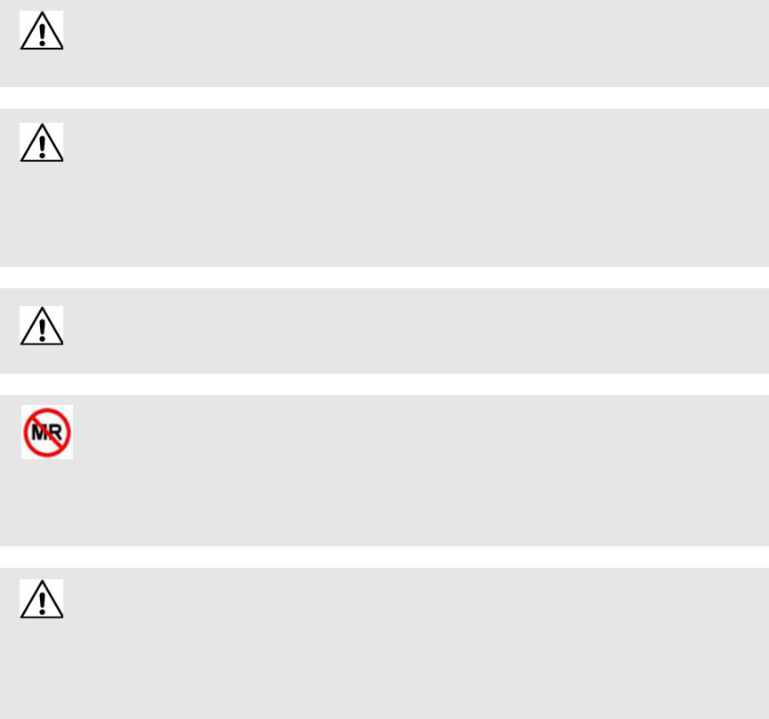
Quick Look Display
The Quick Look Display shows information from the system at remote locations such
as a secondary nurse’s station. When a Red alarm is issued from the system, it is
received through the Quick Look Interface. The type of alarm (Cut Band, Door,
Check), location of the alarm and the transmitter ID are displayed on a large, easy-to-
read 2 x 20 Character Vacuum Fluorescent Displays (VFDs). As new alarms occur,
they appear immediately; the display then begins scrolling through each active alarm.
For more information about the Quick Look Display, see the Quick Look Display and
Interface Installation Guide (0510-1007).
WARNING: When installing the Central Server, proper placement/mounting of the
server is important. Adequate precautions must be taken to prevent the server from
falling, causing injury to persons. Cables must be routed in a way to prevent tripping
hazards.
Any rack mounted Central Server must be install in a controlled environment that
maintains temperature between 50°F and 95°F and humidity between 20% and 50%.
Chapter 1: Equipment Overview
6 Series 7.0 Software (0510-1086-B) - User Guide
9450 System
The transmitters and devices in this section are supported by the 9450 System running the Series 7.0 Software
application.
The 9450 System consist of the following equipment.
•Central Server and Client Computer(s)
•Quick Look Display(s)
•Staff Alert Panel
•Exit Alarm Controller
•Exit Alarm Receiver
•Magnetic Reed Switch
•CodeLock Electromagnetic Lock
•Alarming Band Receivers
•Transmitters
•Smart Sense
•Alarming Band
•Mother
•Wander Management
•CodeWatch
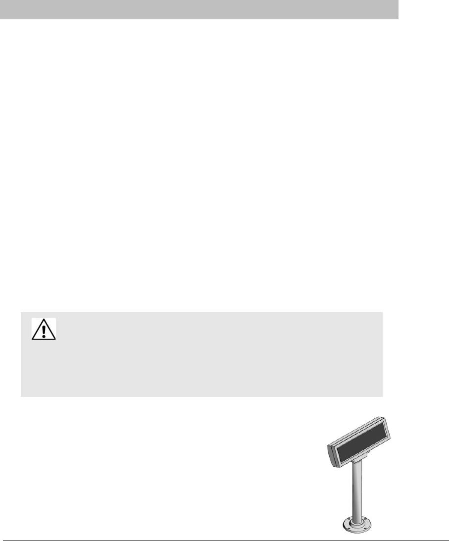
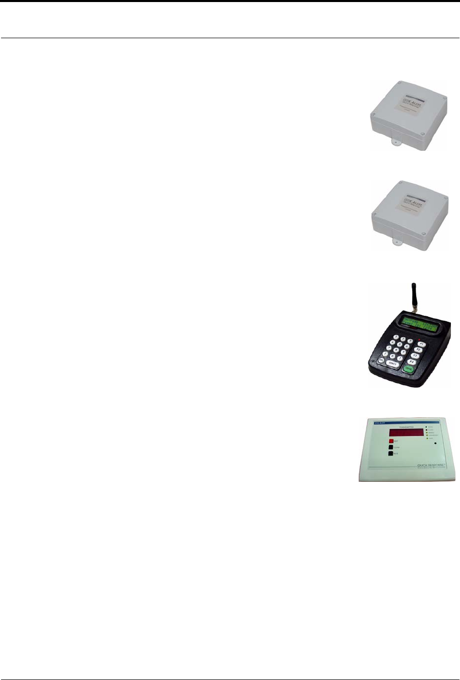
Staff Alert Panel
The Staff Alert Panel receives alarm signals from Exit Alarm Controllers and
Alarming Band Receivers and indicates with a tone and a red LED that an alarm
has occurred. In the space next to each red LED, you can write a brief description
identifying the zone or device that issued the alarm. If your facility requires the
Staff Alert Panel to be visible, it must be located on a wall near the Nurses Station;
or it can be located elsewhere such as a security office, or a phone operator room.
For more information about Staff Alert Panel, see the Staff Alert Panel Installation
Guide (PN 0510-1008).
Series 7.0 Software (0510-1086-B) - User Guide 7
9450 System
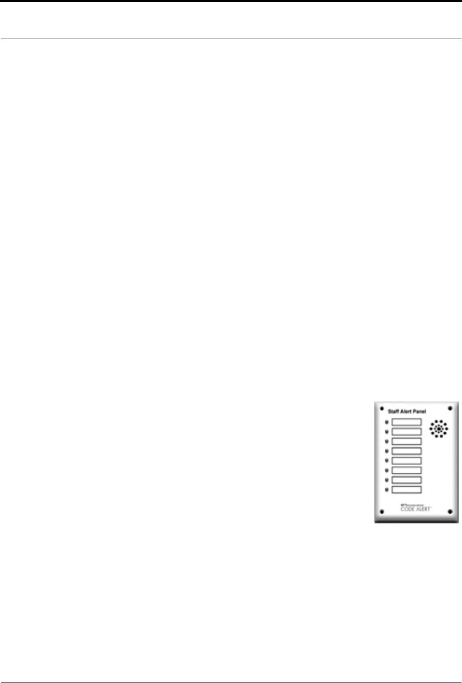
Exit Alarm Controller
The Exit Alarm Controller receives data from the Exit Alarm Receivers and issues an alarm if a transmitter is
detected in the Exit Alarm Zone, and the door is open. The Exit Alarm Controller contains a keypad, and/or
card reader access device, that allows authorized staff to reset the system after an alarm. The Exit Alarm
Controller is the device that triggers the alarm process for the Central Server and Staff Alert. For more
information about the Exit Alarm Controller, see the Delayed Egress Exit Alarm Controller Installation
Guide (PN 0510-1023).
Card Reader Access Device
The Card Reader Access device can be connected to the Exit Alarm Controllers in order to use access cards
for triggering bypass cycles and resetting alarms on the Exit Alarm Controller. The Card Reader Access
device can be an HID proximity card reader or a magnetic/bar code card reader (available at RF
Technologies).
The Card Reader is interfaced through an RS-232 serial communications port between the Card Reader and
the Exit Alarm Controller. The Card Reader and the Exit Alarm Controller may share a common power
supply feed.
The Exit Alarm Zone
An Exit Alarm Zone is the area within range of a door, elevator, hallway, or stairwell that is being monitored
by the system. If a transmitter is detected in an Exit Alarm Zone and the door is open, an alarm sounds at the
exit. If the door is equipped with a CodeLock, when a transmitter enters the Exit Alarm Zone and the door is
closed, it will lock.
The devices that are used in an Exit Alarm Zone are an Exit Alarm Controller, Magnetic Reed Switches, and
Exit Alarm Receivers. Optional devices include CodeLock™ electromagnetic locks, passive infrared (PIR)
detectors, and an External Reset/Bypass Keypad.
Power: The red light indicates that
power is available to the system.
Signal: The yellow light indicates
that a signal has been received
from the Exit Alarm Receivers.
Status: The green light indicates
that the system is in bypass or that
the unit is in alarm or disarmed.
Chapter 1: Equipment Overview
8 Series 7.0 Software (0510-1086-B) - User Guide
Exit Alarm Receiver
Exit Alarm Receivers are low frequency (LF) antennas placed on or near a door frame in an Exit Alarm
Zone. They receive signals from transmitters within a monitored zone and send the signals to the Exit Alarm
Controller, which triggers the alarm process. For more information about Exit Alarm Receivers, see the
DuoLink Exit Alarm Receiver Installation Guide (PN 0510-1003).
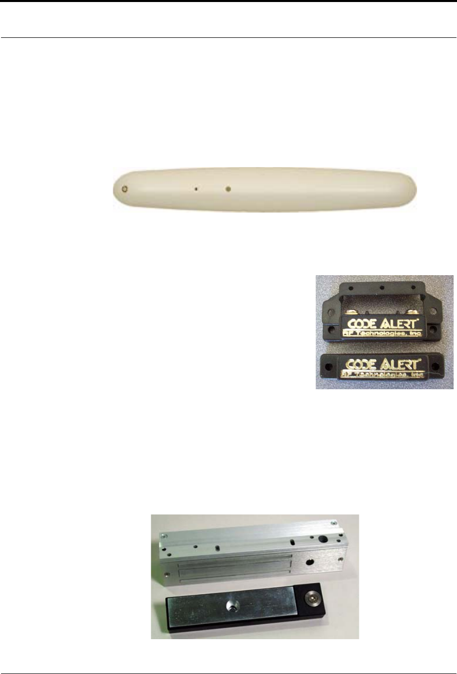
Magnetic Reed Switch
The Magnetic Reed Switch is used by an Exit Alarm Controller to
detect that a monitored door is open. The Magnetic Reed Switch
should be mounted at the top of a door near the non-hinged edge. It
comes in two pieces: a switch and a magnet. The switch is mounted
on the door frame; the magnet is attached directly to the door.
When normally closed (NC) reed switches are used on a double
door, connect the switches in series. The provided Magnetic Reed
Switches are normally closed (indicated with a gold Code Alert
logo) when the doors are closed so that opening either door opens
the switch on that door.
CodeLock Electromagnetic Lock
The CodeLock option is an electromagnetic lock attached to an exit and connected to the Exit
Alarm Controller. If a transmitter is detected in the Exit Zone, the CodeLock activates to help stop
the door from opening for as long as the transmitter is within range of the receivers. Refer to the
CodeLock Electromagnetic Door Lock Installation Guide (PN 0510-1002) for information on
installation and operation.
Series 7.0 Software (0510-1086-B) - User Guide 9
9450 System
Alarming Band Receivers
Alarming Band Receivers are placed strategically throughout the monitoring area to receive signals from the
alarming band transmitters worn by patients. When using the alarming band transmitter, the system provides
an alert if the banding material that holds the transmitter to the patient is tampered with, cut, or opened
without authorization. Multiple receivers are used to ensure reception of the signal if there is an effort made to
shield the transmitter during abduction or elopement attempts. For more information, see the Alarming Band
Receiver Installation Guide (PN 0510-1001).
Alarming Band Zone
An Alarming Band Zone is the area within range of an Alarming Band Receiver, several of which are
mounted below the ceiling tiles of a facility. If a Cut Band or Band Off alarm is triggered in an Alarming
Band Zone, an alarm is sounded on all Client computers assigned to monitor the transmitter’s unit, a message
is displayed in the Event List, and the location of the Alarming Band Receiver that detected the event is
indicated on the map on the Client computer(s). Cut Band and Band Off alarms are also posted on remote
notification devices.
Alarming Band Transmitters
A transmitter is a device that periodically transmits a signal containing data to uniquely identify it from other
transmitters. Some transmitters are also capable of transmitting information to identify that the band has been
cut. These transmitters are referred to as alarming band transmitters.
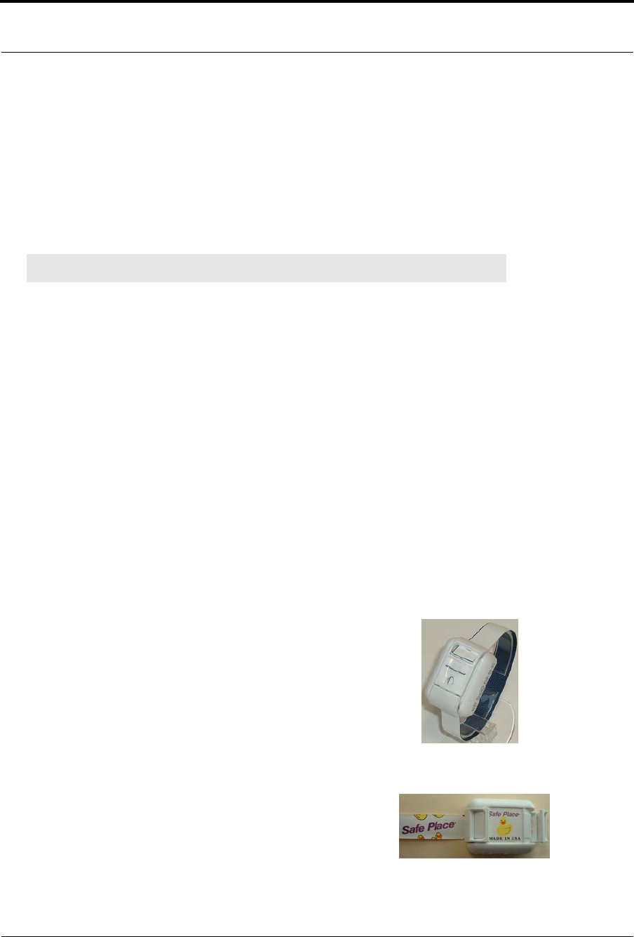
Patient and Infant Transmitters
Patient and Infant transmitters are placed on the ankle or wrist of a patient
or affixed to an asset. The transmitter becomes active once the banding
material remains connected on both sides with banding material in place
for 60 seconds. The 60-second window exists to allow for proper
adjustment of the banding material.
After one minute, the transmitter ID is displayed in the Event List and
information of the patient or asset wearing the transmitter can be associated
with the transmitter using the Admit or Auto-Enroll function. Alarming
band transmitters can be supervised. If a transmitter is configured for
Supervision, and fails to regularly communicate to the system, a No Signal
alarm will result in the Event List at the computer. For more information
about securing, cleaning, and troubleshooting transmitters, refer to the
Patient Transmitter User Guide (PN 0510-1013) or Infant Transmitter
User Guide (PN 0510-1006).
NOTE: The Mother/Infant function requires applicable Alarming Band Receivers.
Patient Transmitter
Infant Transmitter
Chapter 1: Equipment Overview
10 Series 7.0 Software (0510-1086-B) - User Guide
Each transmitter is stamped with a warranty expiration date. This date indicates the date that RF
Technologies’ warranty on that transmitter expires (the last day of the month stamped). If the warranty
period has expired, discard the transmitter immediately.
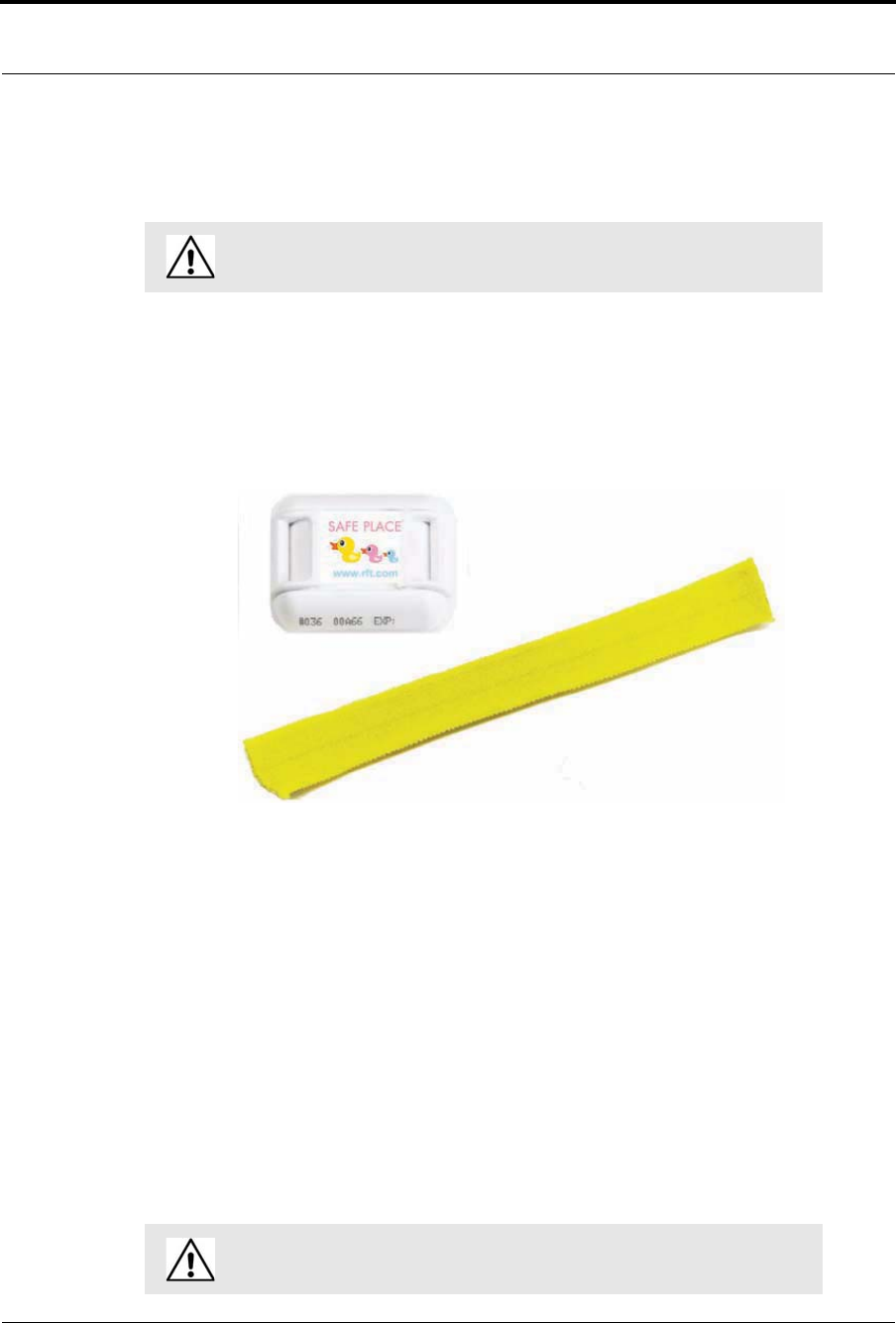
Smart Sense™ Infant Transmitter and Banding Material
The combination of the Smart Sense Infant Transmitter and Banding Material has the capability to recognize
if the transmitter has been removed from an infant. It will also sense if it is tampered with or loose. If a
transmitter is configured for Supervision, and fails to regularly communicate to the system, a No Signal alarm
will result in the Event List at the computer.
The Smart Sense technology uses three measurements to provide tamper detection. Depending on your
facility, one, two or all three measures for tamper detection can be configured for activation.
•Temperature—change in transmitter temperature
•Resistance—no motion detected from the banding material (i.e. band stretching with
normal infant movement)
•Capacitance—change in contact between transmitter and infant
The cloth-like banding material has the capability to stretch or adjust to accommodate infant weight loss, thus
reducing re-banding or adjustments caused by slippage. In addition to Cut band technology, band expansion
is also a key feature for tampering and unauthorized removal detection. If an unauthorized attempt is made to
pull or stretch the banding material, an alert will sound and a Band Off event will be triggered.
Each transmitter is stamped with a warranty expiration date. This date indicates the date that RF
Technologies’ warranty on that transmitter expires (the last day of the month stamped). If the warranty
period has expired, discard the transmitter immediately.
WARNING: Using a transmitter beyond the printed EXP date can result in
system failure and/or an elopement.
WARNING: Using a transmitter beyond the printed EXP date can result in
system failure and/or an abduction.

Series 7.0 Software (0510-1086-B) - User Guide 11
9450 System
Asset Tracking
Alarming band transmitters can be used for asset management. When an alarming band transmitter is
attached to an asset and admitted using the Add Asset admit function, Blue alarms are generated and appear
in the Event List when an attempt is made to remove the assets from an Exit Zone or the band is tampered
with or cut.
Non-Alarming Band Transmitters
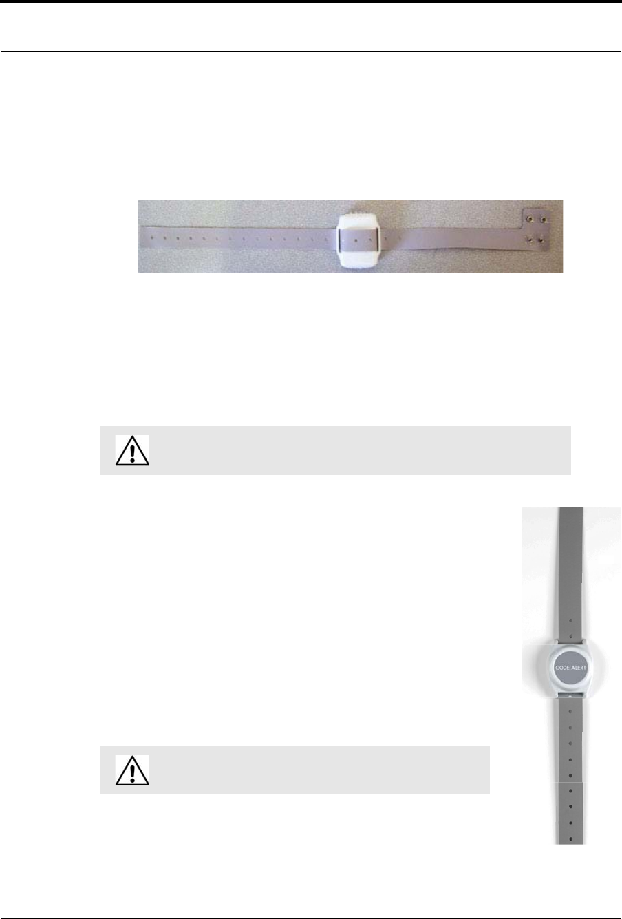
Mother Transmitter
A Mother transmitter is placed on the wrist of a new mother and then linked to an
Infant transmitter worn by her newborn. When the Infant transmitter is in proximity of
the Mother transmitter, the Mother transmitter flashes a green light to indicate that the
Infant and Mother transmitters match. If there is a mismatch, meaning the Infant and
Mother transmitters do not match, the Mother transmitter flashes the red light three
times, and sounds a three beep alarm. A Mismatch Transmitter alarm is also generated in the Event List
at the computer. If there is a linking problem, for example, the Infant transmitter may already be linked
to another Mother transmitter, a Link Transmitter alarm is generated in the Event List at the computer.
In cases where the Mother transmitter is linked but no longer active (e.g. the patient has been
discharged but the transmitter was never cleared) the transmitter will beep after 24 hours of
inactivity. If the transmitter goes undetected and allowed to beep for 15 minutes, it will clear and
discharge itself from the system. Tapping the Mother transmitter will temporarily stop the beeping
but the transmitter remains in a linked state until manually cleared, refer to the Mother Baby Match
Mother Transmitter User Guide (PN 0510-1020). If not cleared, the transmitter will beep again after
another 24 hours of inactivity.
Each transmitter is stamped with a warranty expiration date. This date indicates the date that RF
Technologies’ warranty on that transmitter expires (the last day of the month stamped). If the warranty
period has expired, discard the transmitter immediately.
NOTE: Although the Mother transmitter will link to an Asset transmitter, the software
does not support this functionality. If this happens, clear the Mother transmitter and re-
link the Infant and Mother transmitters.
CAUTION: The Mother transmitter can be worn in the shower; complete
submersion should be avoided. Prolonged submersion may result in equipment
and/or system failure and voids any or all Product Warranty.
WARNING: Using a transmitter beyond the printed EXP date can result in
system failure and/or an abduction.
Chapter 1: Equipment Overview
12 Series 7.0 Software (0510-1086-B) - User Guide
Wander Management Transmitter
A Wander Management transmitter is a wireless, mobile transmitter that can be worn around the wrist or
ankle. An event is reported in the Event List when a patient is near an open monitored door or attempts to
leave an Exit Zone.
The Wander Management transmitter sends a signal to be received by Exit Alarm Receivers. Exit Alarm
Receivers are low frequency (LF) antennas placed on or near a door frame or in an Exit Alarm Zone. They
receive signals from transmitters within a monitored zone and send the signals to the Exit Alarm Controller,
which triggers the alarm process.
The Exit Alarm Controller receives data from the Exit Alarm Receivers and issues an alarm if a resident
wearing a transmitter is detected in the Exit Alarm Zone, and the door is open.
CodeWatch Transmitter
A CodeWatch transmitter is a wireless, mobile transmitter that can be worn around the
wrist or ankle. An event is reported in the Event List when a patient is near an open
monitored door or attempts to leave an Exit Zone
The CodeWatch transmitter sends a signal to be received by Exit Alarm Receivers. Exit
Alarm Receivers are low frequency (LF) antennas placed on or near a door frame or in
an Exit Alarm Zone. They receive signals from transmitters within a monitored zone
and send the signals to the Exit Alarm Controller, which triggers the alarm process.
The Exit Alarm Controller receives data from the Exit Alarm Receivers and issues an
alarm if a resident wearing a transmitter is detected in the Exit Alarm Zone, and the
door is open.
WARNING: Using a transmitter beyond the printed EXP date can result in
system failure and/or an elopement.
WARNING: Using a transmitter beyond the printed EXP date
can result in system failure and/or an elopement.

Series 7.0 Software (0510-1086-B) - User Guide 13
Quick Response System
Quick Response System
Transmitters and devices listed in this section are supported by the Quick Response System running the
Series 7.0 Software application. The Quick Response system includes transmitters that are both carried by the
patient and fixed devices. A fixed device is a stationary device that is assigned to a room or a unit. This device
is not transported with the patient but stays in the unit or room to which it is assigned.
Quick Response devices are entered into the system by placing the device into an alarming state. The system
senses the device when the device goes into alarm and adds it to the device list in the Configuration-Device
window (refer to the Series 7.0 System Administrator Guide). The user must then update the device
information; for example, give the device a name and/or enable features.
The Quick Responses System consist of the following equipment.
•Central Server
•Quick Look Display
•Wireless Receiver
•Repeater
•Locator
•Paging Base
•Back-up Interface
•Pendant Transmitter
•Wall Mount Transmitter
•Pull Cord
•Check-in Pull Cord
•Smoke Detector
•PIR (Passive Infrared) Sensor
•Door/Window Transmitter
•Universal Transmitter
Wireless Receiver
The Receiver is a device that receives signals from the repeater, locator, or QR
transmitters and communicates them to the Central Server. The Receiver can be
supervised; if no information is received by the system from the Receiver for a specified
number of minutes, a Device Fault alarm is generated in the Event List at the computer
monitoring the unit that the Receiver is assigned to.
Chapter 1: Equipment Overview
14 Series 7.0 Software (0510-1086-B) - User Guide
Repeater
A Repeater is a device that receives the signals from Quick Response
transmitter and communicates them to the Receiver. This enables the system to
cover larger facilities. Repeaters are supervised; a routine signal is sent from
each Repeater and if the signal is not received by the system, a Device Fault
event is generated in the Event List at the computer.
Locator
Locators receive signals from Quick Response transmitters, add location data,
and communicates the signals to the receiver. When an event occurs, the map of
your facility will indicate the Locator that received the signal from the alarming
device. Locators are supervised; a routine signal is sent from each Locator and
if the signal is not received by the system, a Device Fault event is generated in
the Event List at the computer.
Paging Base
The Paging Base (optional) sends radio frequency signals to the pager
receiver(s) when events occur. The pager receiver indicates the name, room
number, and event type of the transmitter that issued the alarm.
Back-Up Interface
The Back-up Interface is an optional device that takes over the responsibility of
communicating with the paging base and provides alarm information
(transmitter number only) in the event of an inoperable computer.
NOTE: Please reference Transmitter Report and Device Report to correlate the
transmitter number to the patient or the device. It is recommended to reprint the
Transmitter Report after new patients are admitted and discharged.
Series 7.0 Software (0510-1086-B) - User Guide 15
Quick Response System
Pendant Transmitter
A Pendant transmitter is a wireless, mobile transmitter that can be worn around the neck
or wrist, or attached to a belt. The Pendant transmitter is suitable for use in showers or
baths. To prevent damage to the Pendant transmitter, avoid prolonged submersion.
Since the Pendant transmitter is a mobile device, no installation is required. Simply insert
the battery and assign the transmitter to a resident, assuming the transmitter has been
configured into the system and the transmitter ID number falls within the configured
range. The Pendant transmitter is powered by a replaceable 3-volt battery.
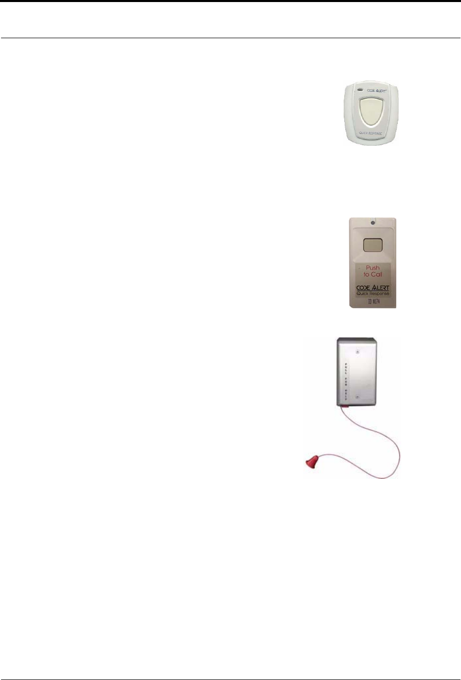
Wall Mount Transmitter
The Wall Mount transmitter may be mounted on a wall. When a resident presses a button
on the transmitter an Assistance Required alarm event is reported Event List at the
computer. If the transmitter is supervised, a routine signal is sent from the transmitter and
if the signal is not received by the system, a Device Fault event is generated in the Event
List at the computer. The Wall Mount transmitter is powered by a replaceable 3-volt
battery.
Pull Cord
A Pull Cord is usually mounted on a wall. This device is used to request staff
assistance and is commonly used in bedrooms and bathrooms. It is suitable for
use in close proximity to showers or baths; however to prevent damage, avoid
any submersion.
An Assistance Required alarm event is reported in the Event List when a
patient pulls a cord. The Pull Cord can be supervised; a routine signal is sent
from the transmitter and if the signal is not received by the system, a Device
Fault event is generated in the Event List at the computer. Pull Cords are
powered by a replaceable 3-volt battery.

Chapter 1: Equipment Overview
16 Series 7.0 Software (0510-1086-B) - User Guide
Check-in Pull Cord
A Check-in Pull Cord enables the staff or patient to push a green button to
check-in. Pressing the green button indicates to the system that the patient has
checked in or been visited by staff. The type of check-in depends on how your
Pull Cord is configured (refer to the Series 7.0 Software Administrator Guide).
Types of check-in
•Patient Check-in—A patient pushes the button to notify the staff that he/
she is awake and does not require assistance.
•Staff Check-in—A staff member pushes the check-in button once they
have checked on a patient.
•Staff Care Complete—A staff member pushes the check-in button in
response to an Assistance Required alarm once the patient has been
checked on and the alarming device is reset. If Joint Commission is
enforced, this will clear the White alarm from the Client computer.
Smoke Detector
If your facility is using wireless smoke detectors in conjunction with your Series 7.0
Software, a Smoke alarm event is reported in the Event List each time a smoke
detector is activated. A smoke detector can be supervised; a routine signal is sent
from the device and if the signal is not received by the system, a Device Fault event
is generated in the Event List at the computer. The Smoke Detector is powered by a
replaceable 3-volt battery.
PIR Sensor
The Passive Infrared (PIR) Sensor is a motion detector used to sense motion in a
room or hallway. Or, it can be used as an Inactivity-Check-in device to sense when
no motion is detected within a set period of time (refer to “Inactivity Check-in” in
the Series 7.0 Software User Guide). An Assistance Required alarm event is
reported in the Event List each time the detector is activated.
A PIR motion detector can be supervised; a routine signal is sent from the device
and if the signal is not received by the system, a Device Fault event is generated in
the Event List. The PIR Sensor is powered by a replaceable 3-volt battery.

Series 7.0 Software (0510-1086-B) - User Guide 17
Quick Response System
Door/Window Transmitter
A Door/Window transmitter is used to protect a door or window against
unauthorized egress. An Exit alarm event is reported in the Event List when a door
or window is opened. The alarm automatically clears when the door or window is
closed.
The Door/Window transmitter comes in two pieces: the transmitter enclosure and a
magnet. The transmitter enclosure is mounted on the door/window frame; the
magnet is attached directly to the door/window. Separating these devices triggers an
alarm. The Door/Window transmitter is powered by a replaceable 3-volt battery.
Universal Transmitter
A Universal transmitter can be used to integrate your facility’s existing equipment
such as backup generators, pull-cord devices, or smoke detectors with the Series 7.0
Software. Universal transmitters come as either NO (normally open) or NC
(normally closed) devices. They automatically activate when the input from a
monitored device has a contact close or open respectively. When this happens, the
Universal Transmitter sends event information to the Central Server.
The Universal transmitter can be placed in the enclosure of an existing device or
inconspicuously mounted near the device. Be sure that the transmitter is not
encased in metal that might block the wireless signal to the Repeater or Receiver.
The Universal transmitter is powered by a replaceable 3-volt battery.
Chapter 1: Equipment Overview
18 Series 7.0 Software (0510-1086-B) - User Guide
9600 Series Wireless Call System
The basic components of the 9600 Wireless Call System consist of the Central Server, the Gateway, the
Router and the transceiver devices. Other components may consist of the Quick Look Router, 32 Zone Staff
Alert Panel, 32 Channel Controller Router and Dome Lights. The 9600 Series Wireless Call System
transceiver devices consist of the following:
•Pull Cord
•Check-in Pull Cord
•Wall Mount
•Nurse Call
•Universal
•Universal Nurse Call
•Door/Window
•Smoke Detector
•PIR Sensor
•Pendant
Gateway
The Gateway receives signals from a Router or transceiver devices and
sends them to the Central Server. The Gateway can be supervised; if no
information is received by the system from the Gateway for a specified
number of minutes, a Device Fault alarm is generated in the Event List
at the computer.
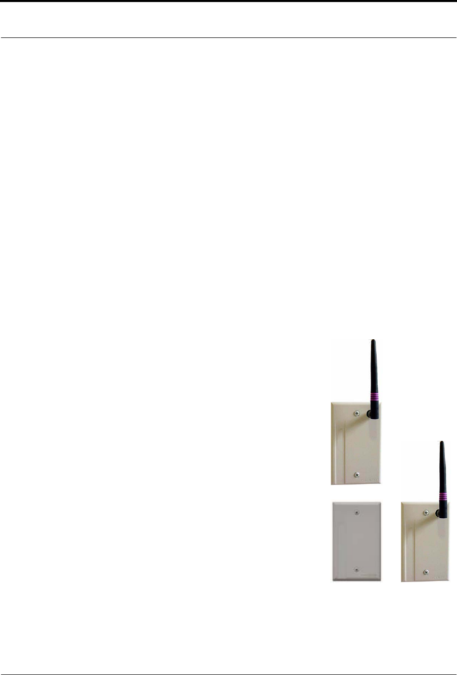
Router
Routers receive signals from transceivers and re-transmit them to the
Gateway. Two factors that affect the placement of Routers are the
availability of a power source and sufficient coverage for the
supervision of transceivers.
There are two variations of Routers, one with an internal antenna and
one with an external antenna for greater range. Routers are supervised; a
routine signal is sent from each Router and if the signal is not received
by the system, a Device Fault event is generated in the Event List at the
computer.
Series 7.0 Software (0510-1086-B) - User Guide 19
9600 Series Wireless Call System
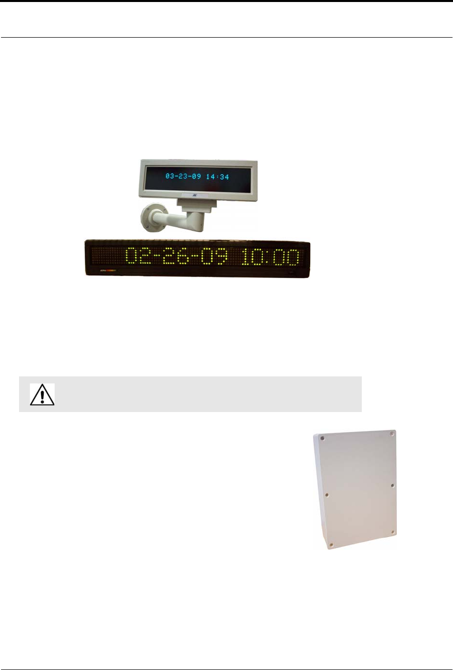
Quick Look Router
A Quick Look Router is an 9600 Series Router connected to a wireless Quick Look Display or High
Visibility Display. When an alarm is sent from the Server to the Router, the wireless display shows the type
of alarm, location data and transceiver number. As new alarms occur, they appear immediately; the display
then begins scrolling through each active alarm.
The Quick Look Router also acts as an integral part of the back-up reflector. Reflector functionally allows the
9600 Series network to take over the responsibility of distributing alarm information to the Quick Look
Routers in the event of an inoperable Server.
Quick Look Routers are supervised; a routine signal is sent from each Quick Look Router and if the signal is
not received by the system, a Device Fault event is generated in the Event List at the computer.
32 Channel Controller Router
The 32 Channel Controller Router is a 9600 Series Router connected to a 32
Channel Controller. When an alarm is sent from the Server to the Router, the 32
Channel Controller acts as a relay switch and turns on the Dome Light mounted
outside the patient’s room. The Dome Light includes two indicator lights: a white
indicator light for low priority alarms and a red indicator light for high priority
alarms.
32 Channel Controller Routers are supervised; a routine signal is sent from each
Quick Look Router and if the signal is not received by the system, a Device Fault
event is generated in the Event List at the computer.
WARNING: Quick Look Routers should not be added to multiple units. Since
Routers are used to determine location, inaccurate location data could result.
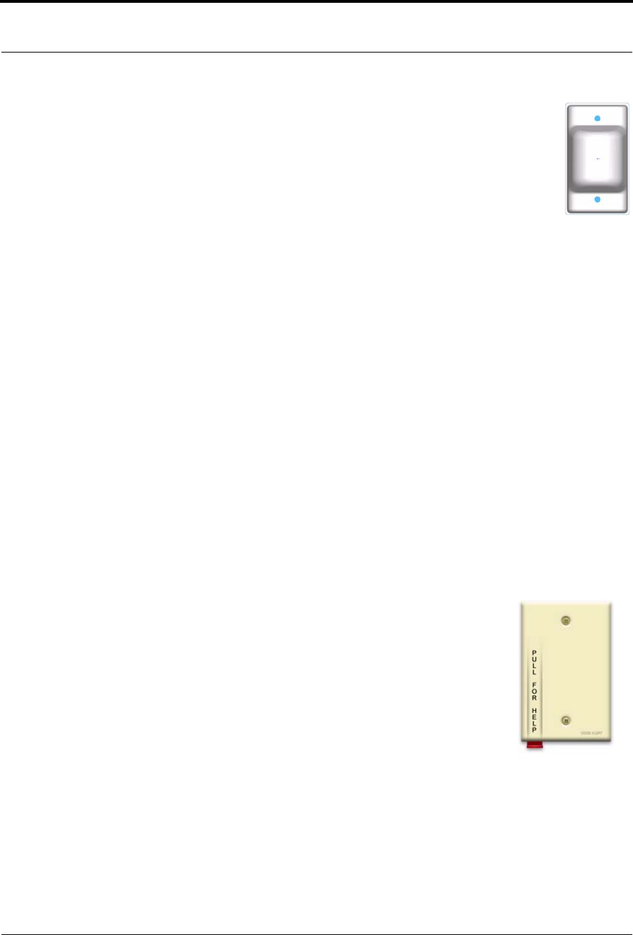
Chapter 1: Equipment Overview
20 Series 7.0 Software (0510-1086-B) - User Guide
Dome Light
The Dome Light includes two different banks of indicator lights: white normal call
indicator light and red emergency call indicator lights.
•Emergency Calls—Emergency calls are indicated by steady illumination of the red
Dome Light associated with the zone or area from which an emergency call has
been placed.
•Normal Calls—Normal calls are indicated by steady illumination of the white Dome
Light associated with the zone or area from which a normal call has been placed.
•Concurrent Emergency and Normal Calls—If an emergency and normal call are placed
at the same time, the red light connected to the emergency station from which a call was
placed will illuminate at the same time as the white light associated with the normal call.
Transceivers
A transceiver is a device that periodically transmits a signal containing data to uniquely identify it from other
transceivers. Additionally, transceivers can receive data back. The transceiver devices listed in this section are
supported by the 9600 Series Wireless Call System running the Series 7.0 Software application. The 9600
Series Wireless Call System includes transceivers that are carried by the patient and fixed devices. A fixed
device is a stationary device that is assigned to a room or a unit. Fixed devices are not transported with the
patient but stay in the unit to which they are assigned.
The transceiver devices are entered into the system by placing the device into an alarming state. The system
senses the device when the device goes into alarm and adds it to the device list in the Configuration-Device
window (refer to the Series 7.0 System Administrator Guide). The user must then update the device
information; for example, give the device a name and/or enable features.
Pull Cord
A Pull Cord is usually mounted on the wall. This device is used to request staff
assistance and is commonly used in bedrooms and bathrooms. It is suitable for use
in close proximity to showers or baths; however to prevent damage, avoid any
submersion.
An Assistance Required alarm event is reported in the Event List when a patient
pulls a cord. The Pull Cord is supervised; a routine signal is sent from the
transceiver and if the signal is not received by the system, a Device Fault event is
generated in the Event List at the computer. Pull Cords are powered by a
replaceable 3-volt battery.
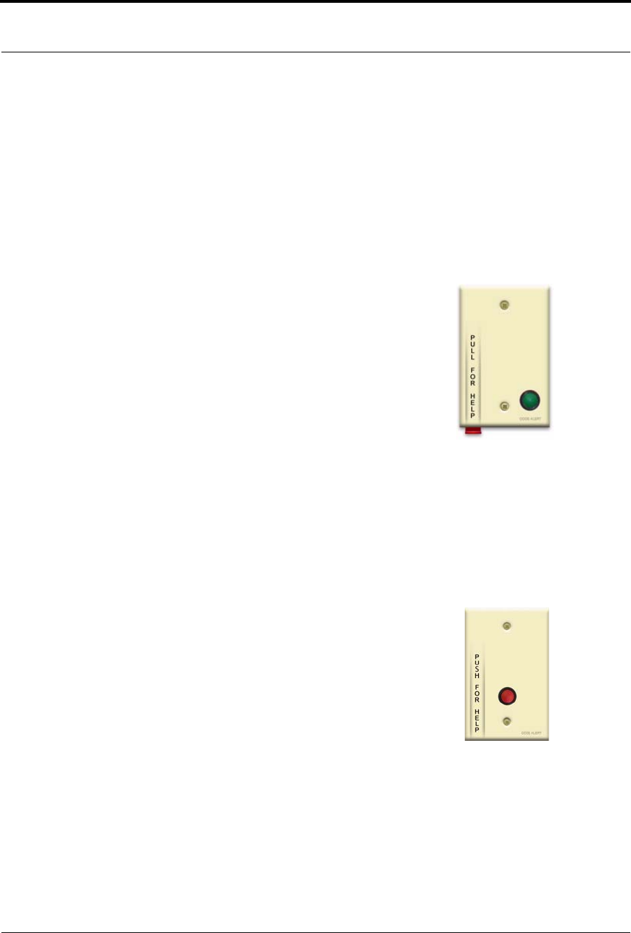
Series 7.0 Software (0510-1086-B) - User Guide 21
9600 Series Wireless Call System
To Call for Assistance
To call for assistance, pull the cord on the Pull Cord transceiver. The red HELP lever comes down indicating
that the transceiver is in an alarm state.
To Clear an Alarm
To clear the alarm and reset the Pull Cord, rotate the red HELP lever back to the up position. The Pull Cord is
now idle and ready for its next usage.
Check-in Pull Cord
A Check-in Pull Cord enables the staff or patient to push a green button to check-in.
Pushing the green button indicates to the system that the patient has checked in or been
visited by staff. The type of check-in depends on how your Pull Cord is configured
(refer to the Series 7.0 Software Administrator Guide).
Check-in types
•Patient Check In—A patient pushes the button to notify the staff that he/she is
awake and does not require assistance.
•Staff Check In—A staff member pushes the check-in button once they have
checked on a patient.
•Staff Care Complete—A staff member pushes the check-in button in response to
an Assistance Required alarm once the patient has been checked on and the
alarming device is reset. If Joint Commission is enforced, this will clear the White
alarm from the Client computer
Wall Mount Emergency Call
A Wall Mount Emergency Call is mounted on the wall. This device is used to request
staff assistance and is commonly used in bedrooms and bathrooms. It is suitable for use
in close proximity to showers or baths; however to prevent damage, avoid any
submersion.
An Assistance Required alarm event is reported in the Event List when a patient pushes
the red button. The Emergency Call is supervised; a routine signal is sent from the
Emergency Call and if the signal is not received by the system, a Device Fault event is
generated in the Event List at the computer. The Wall Mount Emergency Call is
powered by a replaceable 3V battery.
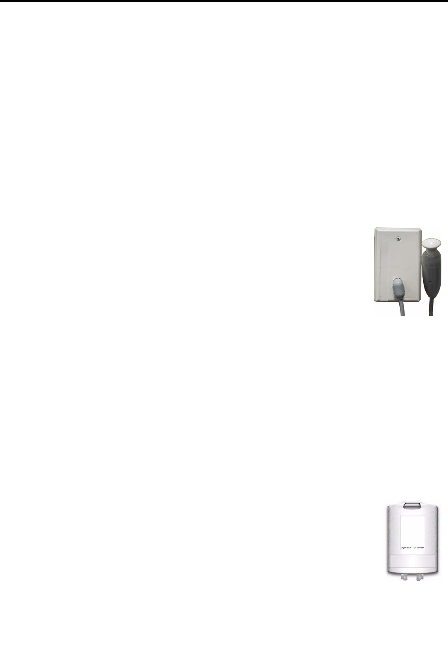
Chapter 1: Equipment Overview
22 Series 7.0 Software (0510-1086-B) - User Guide
To Call for Assistance
To call for assistance, push the red button on the Wall Mount Emergency Call transceiver. When pushed, the
button remains in indicating the device is in an alarm state.
To Clear an Alarm
To clear the alarm and reset the Emergency Call, push the red button again. The button pops out indicating
the transceiver has changes states and is now idle and ready for its next usage.
Nurse Call Transceiver
A Nurse Call transceiver is affixed near the bed of the patient. An Assistance Required
alarm event is reported in the Event List when a patient pushes the button on the Nurse
Call transceiver. The Nurse Call transceiver is supervised; a routine signal is sent from
the transceiver and if the signal is not received by the system, a Device Fault event is
generated in the Event List at the computer. The Nurse Call transceiver is powered by
a replaceable 3V battery.
Since the Nurse Call transceiver Cord sets, which plugs into the Nurse Call
transceiver, require a normally closed (NC) contact, you must configure the Pull Cord
transceiver’s Contact Type as normally closed (refer to the section, “Update 9600 Series Pull Cord” in the
Series 7.0 Software Administrator’s Guide).
To Call for Assistance
To call for assistance, firmly press down and release the plunger on the Nurse Call. The plunger stays down
indicating that the transceiver is in an alarm state.
To Clear an Alarm
To clear an alarm or to reset the Nurse Call transceiver, pull the plunger up. When in the up position, the
transceiver is idle and ready for its next usage.
Universal Transceiver
A Universal transceiver can be used to integrate your facility’s existing equipment
such as backup generators, pull-cord devices, or smoke detectors with the software.
Universal transceivers can be set as either NO (normally open) or NC (normally
closed) devices. They automatically activate when the input from a monitored device
has a contact close or open respectively. When this happens, the Universal transceiver
sends event information to the Central Server.
The Universal transmitter can be placed in the enclosure of an existing device or inconspicuously mounted
near the device. Be sure that the transmitter is not encased in metal that might block the wireless signal to the
Repeater or Receiver. The Universal transmitter is powered by a replaceable 3-volt battery.

Series 7.0 Software (0510-1086-B) - User Guide 23
9600 Series Wireless Call System
Universal Nurse Call
A Universal Nurse Call is affixed near the bed of the patient. An Assistance Required alarm event is reported
in the Event List when a patient pushes the button on the Universal Nurse Call. The Universal Nurse Call is
supervised; a routine signal is sent from the transceiver and if the signal is not received by the system, a
Device Fault event is generated in the Event List at the computer. The Universal Nurse Call is powered by a
replaceable 3-volt battery.
To Call for Assistance
To call for assistance, firmly press down and release the plunger on the Nurse Call. The plunger stays down
indicating that the transceiver is in an alarm state.
To Clear an Alarm
To clear an alarm or to reset the Nurse Call transceiver, pull the plunger up. When in the up position, the
transceiver is idle and ready for its next usage.
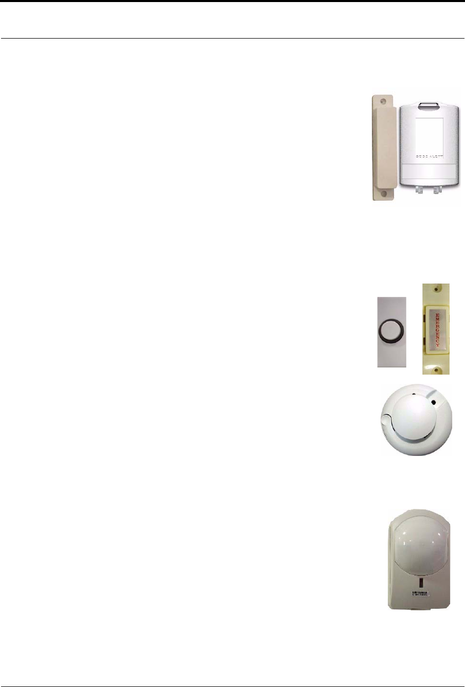
Chapter 1: Equipment Overview
24 Series 7.0 Software (0510-1086-B) - User Guide
Door/Window Transceiver
A Door/Window transceiver is used to protect a door or window against
unauthorized egress. An Exit alarm event is reported in the Event List when a
monitored door or window is opened. The alarm automatically clears when the
door or window is closed. The Door/Window transceiver is supervised; if no
information is received by the system from the transceiver for a specified number
of minutes, a Device Fault alarm is generated in the Event List at the computer.
The Door/Window transceiver comes in two pieces: the transceiver enclosure and
a magnet. The transceiver enclosure is mounted on the door or window frame; the
magnet is attached directly to the door or window. An alarm triggers when the
devices are separated. The Door/Window transceiver is powered by a replaceable
3-volt battery.
Reset Button
There are two types of reset buttons. If your Door/Window transceiver comes
with a reset button, the alarm must be reset at the door by pressing the reset button
once the door/window is closed. The Door/Window transceiver comes in three
pieces: the transceiver enclosure, a magnet and a reset button.
Smoke Detector
If your facility is using wireless Smoke Detectors in conjunction with your Series
7.0 Software, a Smoke alarm event is reported in the Event List each time a
Smoke Detector is activated. A Smoke Detector is supervised; a routine signal is
sent from the device and if the signal is not received by the system, a Device Fault
event is generated in the Event List at the computer. The Smoke Detector is
powered by a replaceable 3-volt battery.
PIR Sensor
The Passive Infrared (PIR) Sensor is a motion detector used to sense motion in a
room or hallway. Or, it can be used as an Inactivity-Check-in device to sense
when no motion is detected within a set period of time. An Assistance Required
alarm event is reported in the Event List each time the detector is activated.
A PIR motion detector can be supervised; a routine signal is sent from the device
and if the signal is not received by the system, a Device Fault event is generated in
the Event List. The PIR Sensor is powered by a replaceable 3-volt battery.
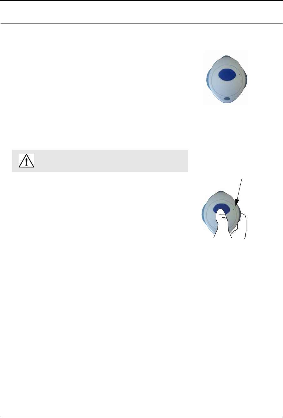
Series 7.0 Software (0510-1086-B) - User Guide 25
9600 Series Wireless Call System
Pendant Transceiver
A Pendant transceiver is a wireless, mobile transceiver that can be worn around the
neck or wrist, or attached to a belt. The protective boot protects the Pendant transceiver
against dropping and water ingress. However to prevent water damage, avoid
prolonged submersion and direct contact with a water stream.
The Pendant can be supervised; if no information is received by the system from the
Gateway for a specified number of times, a No Signal alarm is generated in the Event
List at the computer. Since the Pendant is a mobile device, no installation is required.
Simply insert the battery and set up the Pendant transceiver for use. The Pendant is
powered by a replaceable 3-volt battery. When the battery is low, the Pendent
sends a Low Battery notification.
To Call for Assistance
To call for assistance, firmly press and hold the blue button on the transceiver (for
about a second). Release the button, the green light flashes a series of times to indicate
the transceiver is in an alarm state. If the transceiver flashes red, the signal is blocked.
Move to another area of the room until the signal transmits (flashes green).
To Clear an Alarm
To clear an alarm or to reset the Pendant transceiver, rapidly but firmly press and
release the blue button on the transceiver six (6) times within three (3) seconds (be sure
to see the green light flash for each push). The green light flashes a series of times to
indicate the transceiver has changed states and is now idle and ready for its next usage.
If the transceiver flashes red, the signal is blocked. Move to another area of the
room until the signal transmit (flashes green).
WA R N I N G: You must replace the Pendant battery within
seven days after receiving a Low Battery notification.
Flashing green light
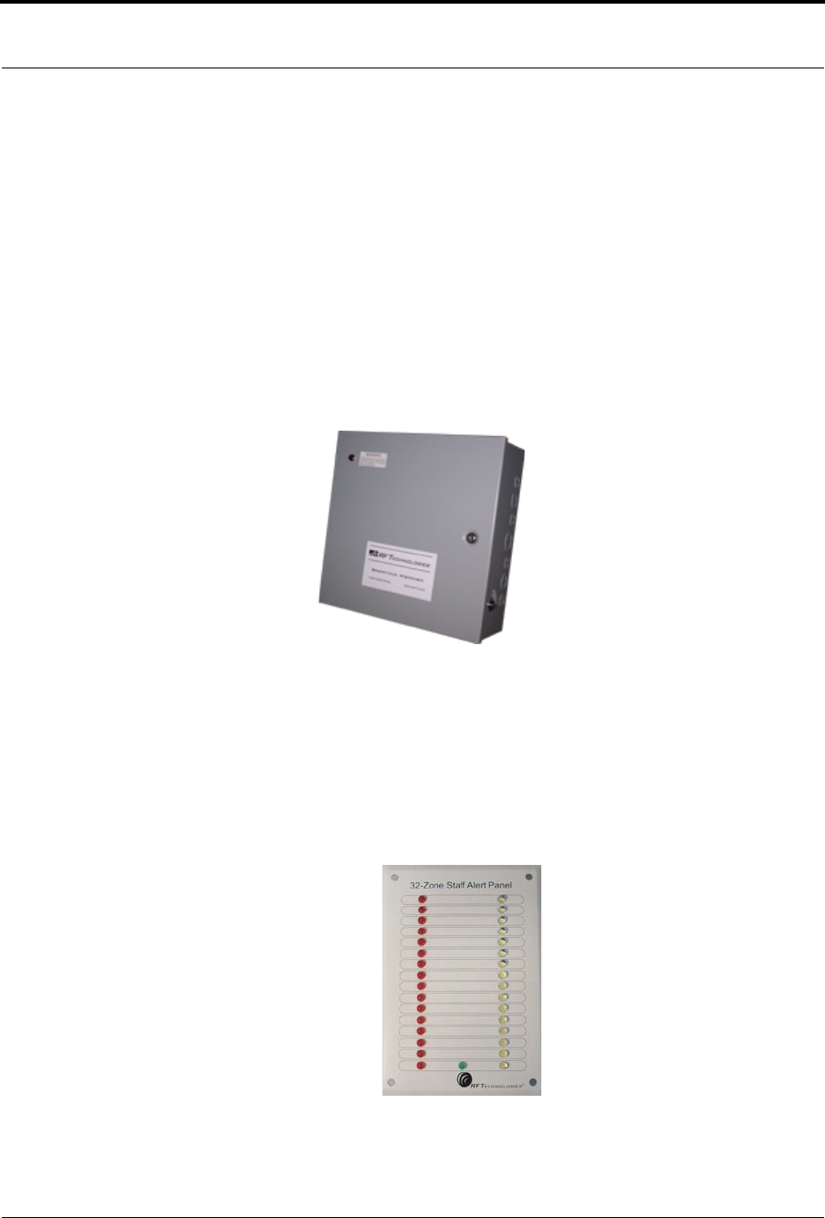
Chapter 1: Equipment Overview
26 Series 7.0 Software (0510-1086-B) - User Guide
9500 Series Wired System
The 9500 Series Wired System consist of a 15 amp Class II Central Power Supply, a 9500 Series 32 Zone
Staff Alert Panel for audible and visual alarms, a visual 9500 Series Dome Light positioned outside the
resident's room, and a 9500 Series Assistance Call device to initiate an alarm. When a call is initiated from an
Assistance Call device, the Dome Light illuminates and an audible and visual alarm sounds at the Staff Alert
Panel. Refer to the 9500 Series Wired Nurse Call Installation Manual (PN 0510-1061) for detailed
information on installing the 9500 Series Wired System.
Central Power Supply
The Central Power Supply is used to connect the 9500 Series Dome Lights to a single power
source. The Central Power Supply eliminates the need to run 120VAC to each detection zone.
Refer to the Class II Central Power Supply Installation Guide (0510-1036) for detailed information
on installing the Central Power Supply.
32 Zone Staff Alert Panel
The 32 Zone Staff Alert Panel receives alarm signals from the Assistance Call device and indicates with a
tone and a red or white light that an alarm has occurred. In the space next to each light, you can affix a label
description identifying the zone or device that issued the alarm.

Series 7.0 Software (0510-1086-B) - User Guide 27
9500 Series Wired System
Dome Light
The Dome Light has two different banks of lights: white normal call indicator lights and
red emergency call indicator lights.
•Emergency Calls—Emergency calls are indicated by steady illumination of the red
Dome Light associated with the zone or area from which an emergency call has been
placed.
•Normal Calls—Normal calls are indicated by steady illumination of the white Dome
Light associated with the zone or area from which a normal call has been placed.
•Concurrent Emergency and Normal Calls—If an emergency and normal call are placed
at the same time, the red light connected to the emergency station from which a call was
placed will illuminate at the same time as the white light associated with the normal call.
There is no requirement for replacement of lights. If for any reason the white or red lights are no
longer functional it is necessary to replace the entire Dome Light. If the Dome Light does not
operate as described, contact qualified service personnel. There are no user serviceable parts on the
Dome Lights.
Assistance Call Devices
A 9500 Series Assistance Call device is a device used to initiate an alarm. There are two Assistance Call
devices used with the 9500 Series Wired call System, Nurse Call and Pull Cord.
Nurse Call
The Nurse Call device allows residents to easily summon help with the
push of a button. The Nurse Call device is generally affixed near the bed
of a resident for easy access.
Pull Cord
The Pull Cord device allows residents to easily summon help with
the pull of the cord. When the cord is pulled, a visual display
“flag” appears assuring them that help was called.
The Pull Cord device is suitable for use in close proximity to
showers or baths; however, to prevent damage, avoid any
submersion.
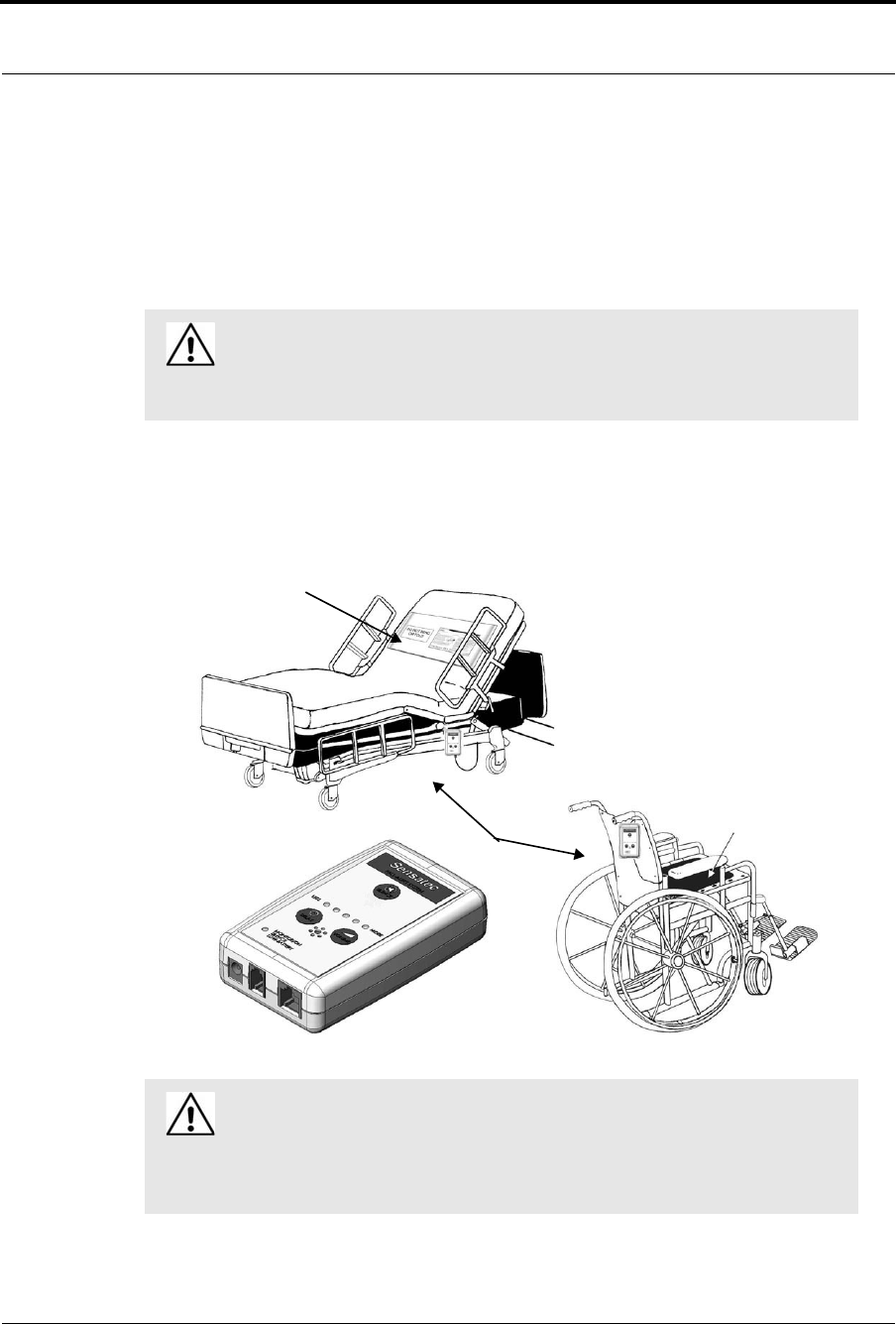
Chapter 1: Equipment Overview
28 Series 7.0 Software (0510-1086-B) - User Guide
Fall Management System
The Fall Management System provides restraint-free monitoring of a patient who may try to leave a bed or
chair without assistance. The Fall Management System can be configured to interface with the software
along with your facility’s nurse call system. An Assistance Required alarm is activated in response to a Fall
Management System alert when interfaced with the Series 7.0 Software.
The Sensor Pad of the Fall Management System is placed on a patient’s bed or chair and connected
to a Control Unit. If a patient removes his or her weight from the Sensor Pad, the Control Unit
issues an audible alert. Refer to the applicable Control Unit’s manual for detailed information about
using the Fall Management System.
WA R N I N G: The Fall Management System may not be suitable for patients who
are “AT HIGH RISK FOR FALL.” Other monitoring measures may also be
required. The Fall Management System should not be a substitute for routine visual
monitoring protocol by caregiving personnel.
WA R N I N G: Due to the possibility of strangulation, all cables should be routed
away from the patient’s throat. When securing the strap, take up any extra slack in
the cord that may become tangled with a patient’s bed or chair. Failure to do so may
result in patient injury. This device should not be used in the presence of flammable
anesthetic mixtures.
Control Unit
Sensor Pad
Sensor Pad
Series 7.0 Software (0510-1086-B) - User Guide 29
Fall Management System Nurse Call
Fall Management System Control Unit
The Fall Management System Control Unit is connected to a Fall Management System Sensor Pad and
attached to a patient’s bed or chair, out of reach of the patient. If a patient attempts to get up, the Control Unit
sounds an alert. An alert can be annunciated in the form of a buzzer. Staff can also be alerted via your
facility’s nurse call system or the 9450 software if available. An Assistance Required alarm is activated in
response to a Fall Management System alert when interfaced with the Series 7.0 Software. The Control Unit
is powered by a 9-volt alkaline battery or by a plug-in power supply.
Fall Management System Sensor Pad
Fall Management System Sensor Pads can be used on most standard beds or chairs in your facility. They
are disposable, intended for single-patient use, and warranted for 7, 30, 90, or 180 days (offering
for pads are subject to change, contact Customer Care at 1-800-669-9946 for the most current
offering). The Sensor Pads have a limited expected useful life. You must record the date the
warranty expires in the area provided on the label. You must not use the sensor pad after the in-
service warranty has expired.
Fall Management System Nurse Call
Your facility can use the Fall Management System in conjunction with your Nurse Call System. Simply
insert the modular jack into the nurse call jack on the control unit then insert the other end of the cable into the
jack on the nurse call system’s bedside wall plate.
When the nurse call cable is plugged in, the control unit sounds an audible alert and the nurse call output is
active during an alarm. If the volume on the control unit is adjusted to its lowest setting, the alarm will not
sound at the control unit but will still register at the nurse call output.
The nurse call system varies in functionality. Consult your facility’s nurse call system documentation to
ensure proper functionality when connecting the Fall Management System to it.
WARNING: If the keys on the Control Unit are worn or damaged, you must
stop using the Control Unit and contact RF Technologies.
WARNING: Pad may become damaged when used on a dynamic mattress
(air, water, etc.). Correct operation should be confirmed at every patient
rotation.
WARNINGS: The control unit will not alarm unless properly connected to the
nurse call system.
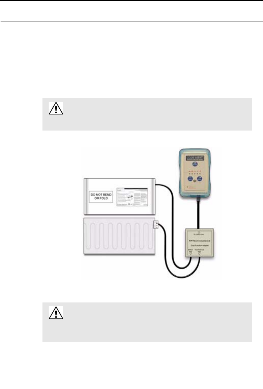
Chapter 1: Equipment Overview
30 Series 7.0 Software (0510-1086-B) - User Guide
Advanced 3-Way Care Solution
The Advanced 3-Way Care Solution has been designed to assist in the areas of Fall Management,
Incontinence Detection and Re-position Reminder. The system can be used to address all three areas of care
or to assist with a single area. The system functions as a stand-alone system or can be configured to interface
with the Series 7.0 Software along with your facility’s nurse call system. When interfaced with the Series 7.0
Software, a Fall, Wet or Turn alarm is activated in response to the applicable event.
WA R N I N G: The Advanced 3-Way Care Solution may not be suitable for patients
who are “AT HIGH RISK FOR FALL.” Other monitoring measures may also be
required. The Advanced 3-Way Care Solution should not be a substitute for routine
visual monitoring protocol by caregiving personnel.
WA R N I N G: Due to the possibility of strangulation, all cables should be routed
away from the patient’s throat. When securing the strap, take up any extra slack in
the cord that may become tangled with a patient’s bed or chair. Failure to do so may
result in patient injury. This device should not be used in the presence of flammable
anesthetic mixtures.
Series 7.0 Software (0510-1086-B) - User Guide 31
Advanced 3-Way Care Solution
Advanced 3-Way Control Unit
The Advanced 3-Way Care Control Unit connects to a sensor pad and attaches to a patient’s bed or chair, out
of reach of the patient. If using the Control Unit for Fall Management or Re-position Reminder, connect the
Motion Sensor Pad. If using the Control Unit for Incontinence Detection, connect the Incontinence Sensor
Pad. To simultaneously address all three applications, insert the Dual Function Adapter and plug in the
Motion Sensor Pad and the Incontinence Sensor Pad into their respective jacks in the adapter. The Control
Unit is powered by a 9-volt alkaline battery or by a plug-in power supply.
Advanced 3-Way Care Sensor Pads
The sensor pads of the Advanced 3-Way Care Solution is placed on a patient’s bed or chair and
connected to a Advanced 3-Way Care Control Unit. Refer to the applicable Control Unit’s in-service
manual for detailed information about using the Control Unit with the sensor pads.
Motion Sensor Pad
The Motion Sensor Pad is used for Fall Management and Re-Position Reminder monitoring. They are
disposable, intended for single-patient use, and warranted for 30 days (offering for pads are subject
to change, contact Customer Care at 1-800-669-9946 for the most current offering). When used for
Fall Management, if a patient removes his or her weight from the Motion Sensor Pad, the Control Unit
flashes the green light and beeps to alert the caregiver.
When used for a Re-position Reminder, the Motion Sensor Pad connects to the Control Unit to allow you to
select a pre-programmed time interval to remind you to change/vary the position of a patient in their bed.
When the selected time interval expires, the Control Unit will alert the caregiver that it is time to reposition
the patient.
Incontinence Sensor Pad
The DriTec Incontinence Sensor Pad comes on a roll and is perforated in one-foot sections to allow you to
tear off only what is needed. It is recommended that you use three sheets for a bed and one for a chair. Prior to
tearing, fold at the perforation to ensure that the pad tears freely from the roll.
The Incontinence Sensor Pad connects to the Control Unit via the Incontinence Sensor Clip. When
incontinence is sensed from the Incontinence Sensor Pad, the Control Unit flashes the green light and beeps
to alert the caregiver.
WA R N I N G: If the keys on the Control Unit are worn or damaged, you must
stop using the Control Unit and contact RF Technologies.
WA R N I N G: Pad may become damaged when used on a dynamic mattress
(air, water, etc.). Correct operation should be confirmed at every patient
rotation.
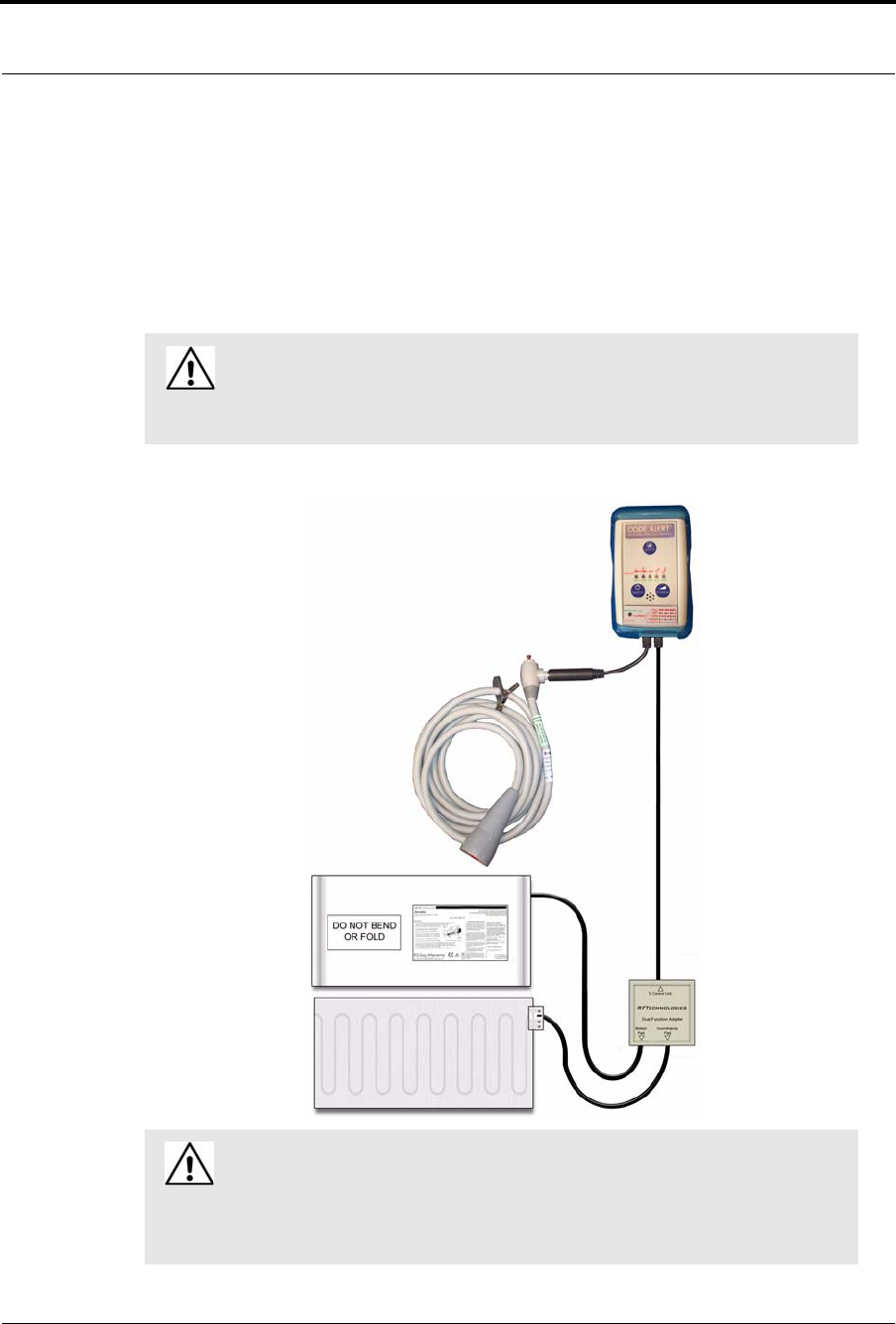
Chapter 1: Equipment Overview
32 Series 7.0 Software (0510-1086-B) - User Guide
Advanced 4-Way Care Solution
The Advanced 4-Way Care Solution has been designed to assist in the areas of Fall Management,
Incontinence Detection, Re-position Reminder and Nurse Call (call for assistance). The system can be used
to address all four areas of care or to assist with a single problem area. The system functions as a stand-alone
system or can be configured to interface with the Series 7.0 Software. When interfaced with the Series 7.0
Software, a Fall, Wet, Turn or Assistance Required alarm is activated in response to the applicable event.
WA R N I N G: The Advanced 4-Way Care Solution may not be suitable for patients
who are “AT HIGH RISK FOR FALL.” Other monitoring measures may also be
required. The Advanced 4-Way Care Solution should not be a substitute for routine
visual monitoring protocol by caregiving personnel.
WARNING: Due to the possibility of strangulation, all cables should be routed
away from the patient’s throat. When securing the strap, take up any extra slack in
the cord that may become tangled with a patient’s bed or chair. Failure to do so may
result in patient injury. This device should not be used in the presence of flammable
gas mixtures.
Series 7.0 Software (0510-1086-B) - User Guide 33
Advanced 4-Way Care Solution
Advanced 4-Way Control Unit
The Advanced 4-Way Care control unit attaches to a patient’s bed or chair, out of reach of the patient. It
connects to a Motion sensor pad, an Incontinence Detection pad and a Nurse Call cord set. If using the control
unit for Fall Management or Re-position Reminder, connect the Motion sensor pad. If using the control unit
for Incontinence Detection, connect the Dri Tec sensor pad. To allow Nurse Call functionality, connect the
Nurse Call cord set.
The control unit is powered by a 9-volt lithium battery or by a plug-in power supply. To simultaneously
address all four applications, insert the Dual Function Adapter and plug in the Motion sensor pad and the
Dri Tec sensor pad into their respective jacks in the adapter. Then insert the Nurse Call modular jack cable
into the applicable jack on the control unit and plug the Nurse Call cord set into the modular jack.
Advanced 4-Way Care Sensor Pads
The sensor pads for the Advanced 4-Way Care Solution are placed on a patient’s bed or chair and
connected to the Advanced 4-Way Care control unit. Refer to the applicable control unit’s in-service
manual for detailed information about using the control unit with the sensor pads.
Motion Sensor Pad
The Motion sensor pad is used for Fall Management and Re-Position Reminder monitoring. They are
disposable, intended for single-patient use, and warranted for 30 days (offerings for pads are subject to
change, contact Customer Care at 1-800-669-9946 for the most current offerings). When the patient’s weight
is removed from the pad, the control unit beeps three times every second to alert caregivers. The status
indicator light flashes red in conjunction with the beeps for a visual alert.
When used for a Re-position Reminder, the Motion sensor pad connects to the control unit to allow you to
select a pre-programmed time interval to remind you to change/vary the position of a patient in their bed. At
the end of the monitoring period, the control unit beeps once every second indicating the time interval has
expired. A red status indicator light flashes in conjunction with the beeps for a visual alert.
The Re-position Reminder light on the control unit also flashes red to indicate the specific bed position that
the patient was left in at the beginning of the monitoring period.
WARNING: If the keys on the control unit are worn or damaged, you must
stop using the control unit and contact RF Technologies.
WARNING: Pad may become damaged when used on a dynamic mattress
(air, water, etc.). Correct operation should be confirmed at every patient
rotation.
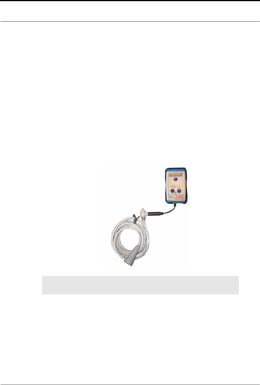
Chapter 1: Equipment Overview
34 Series 7.0 Software (0510-1086-B) - User Guide
Incontinence Sensor Pad
The Dri Tec Incontinence sensor pad comes on a roll and is perforated in one-foot sections to allow you to
tear off only what is needed. It is recommended that you use three sheets for a bed and one for a chair. Prior to
tearing, fold at the perforation to ensure that the pad tears freely from the roll.
The Dri Tec sensor pad connects to the control unit via the Dri Tec Sensor Cord. When an incontinence event
is detected, the control unit beeps twice every second to alert caregivers. A red status indicator light flashes in
conjunction with the beeps for a visual alert.
Advanced 4-Way Care with Nurse Call
To use the Advanced 4-Way Care System with the Nurse Call accessory, connect the Nurse Call
modular jack cable to the control unit. Then connect the Nurse Call cord set into the modular jack. Nurse Call
monitoring starts when the cord set is connected.
When a patient pushes the button on the Nurse Call cord set, an Assistance Required alarm is generated. The
control unit beeps once every 3-seconds to alert caregivers and a red status indicator light flashes in
conjunction with the beeps for a visual alert.
NOTE: The Nurse Call cord set is gravity fed and must always be positioned upright as
shown. False nurse calls may occur if not positioned properly.

Series 7.0 Software (0510-1086-B) - User Guide 35
Messaging Services
Messaging Services
Event Messaging
The Event Messaging system allows staff members to be notified of system events. When an event occurs,
the designated staff is summoned, via pager, email, text message or phone to respond to the situation. Each
messaging media can be assigned to a messaging group, which can be configured to receive messages
specific to that group (nursing staff, maintenance, etc.). Messages may be sent to single message media or
sent to entire groups at once.
A Message Unit is the top tier of the Event Messaging system. Each Message Unit can be comprised of a
number of Messaging Groups and a configured list of alarms and events that trigger messages. For example,
Messaging Unit “A” can be configured to receive messages for Cut Band, No Signal and Client Missing
events. Message Unit “B” may be configured to respond to the same events as Messaging Unit “A” with the
addition of Door Open and Device Fault events.
Depending on the needs of your facility, a Messaging Group can be included in more than one unit. In other
words, Messaging Group “2” can be included in Messaging Unit “A” and Messaging Unit “B”. If no alarms
are selected for a Messaging Unit, alarms will default to a Messaging Group. Shift selections can also be
selected to indicate that, within a specified shift’s time period, all messages will be sent to that shift.
Messaging Delays, Retries and Escalation
Messaging Delay allows the user to enter the number of seconds between an event and the messaging of
designated staff. This delay provides enough time for the system to transmit location information to the Client
computer(s). Messaging Delay is set by the installer and should not be changed without consulting a factory-
trained administrator.
The Messaging Retries features will retry a message after a specified number of minutes for any event to
which there is no response. Once a message has been retried the configured amount of times, the message can
be escalated to another Messaging Group.
Messaging escalation is intended to ensure that staff will respond to an emergency call. If a message is sent to
a Messaging Group and the relevant staff does not respond within a specified period, the call will escalate to
another Messaging Group. It is recommended that the final group be comprised of all the messaging media in
the building. The final group will continue to be messaged until the call is answered. The system does not roll
over to the first group again.
NOTE: White alarms for messaging do not escalate or retry. A white alarm message is
only sent once.

Chapter 1: Equipment Overview
36 Series 7.0 Software (0510-1086-B) - User Guide
Walkie-Talkie
The Walkie-Talkies alert staff members when specific events occur. Staff members equipped with a walkie-
talkie will receive an audible message for triggered events. Triggering events for the walkie-talkie are
configured in the Configuration menu. The options are: Assistance Required, No Signal, Cut Band Alarm,
and Door Alarm. If your system includes the Advanced 3-Way or 4-Way Care system, additional options
include Fall, Wet and Turn.
Walkie-Talkie configurations allows you to set the number of seconds between the start of an alarm and
when the alarm is repeated. This is referred to as a repeat interval. The repeat interval count down starts as
soon as the walkie-talkie alarm sounds. Therefore, depending on the number of seconds selected for a repeat
interval, an alarm may repeat only seconds after the first alarm stops.
Series 7.0 Software (0510-1086-B) - User Guide 37
Chapter 2
Software Features
Introduction
This chapter provides details about starting the software and features of the software. It describes the use of
the touchscreen monitor, the window conventions and the Main operating window. From the Main
application window you can access menu items necessary to operate your system.
Start the Software
After installation, the software automatically starts when you turn on the computer. A splash screen with the
logo and the name of the system is displayed while the program loads. This screen contains the version
number of your software.
FIGURE 2.1: Startup Splash Screen for the Code Alert System
Sleep Mode
Sleep mode refers to a low power mode that turns your computer’s monitor off after a certain period of time.
If your monitor is in sleep mode a simple touch of the mouse or keyboard usually wakes the monitor within
seconds. Additional, any new alarms detected on a Client computer that would maximize the application will
reawaken the monitor.
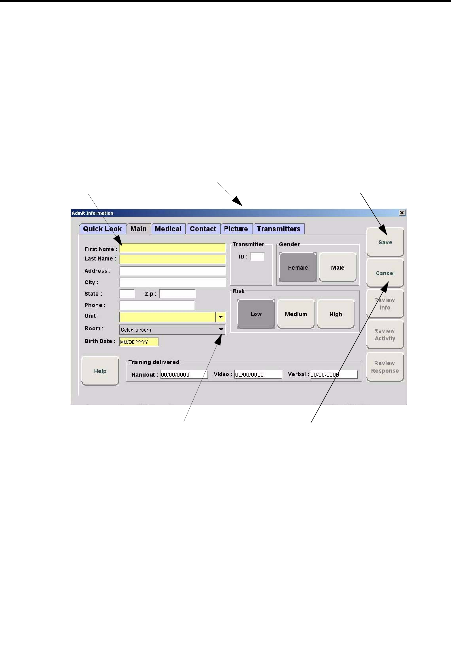
Chapter 2: Software Features
38 Series 7.0 Software (0510-1086-B) - User Guide
Window Conventions
When you perform a function using the software, a window appears. Here, you can enter data or select
options. The software is designed for use with a touchscreen monitor. The user buttons are large and easy to
use. All daily functions, such as admitting and transferring, can be performed using the touchscreen monitor;
configuration operations may require you to use the keyboard and mouse. For more information about
configuration options, see the Series 7.0 Software Administrator Guide.
FIGURE 2.2: Sample Window
Drag the title bar to move the window.
Type information in the text boxes.
Click Save to accept changes and close
the window or dialog box.
Use the arrow to select information from the drop-down Click Cancel to close the window or dialog box.
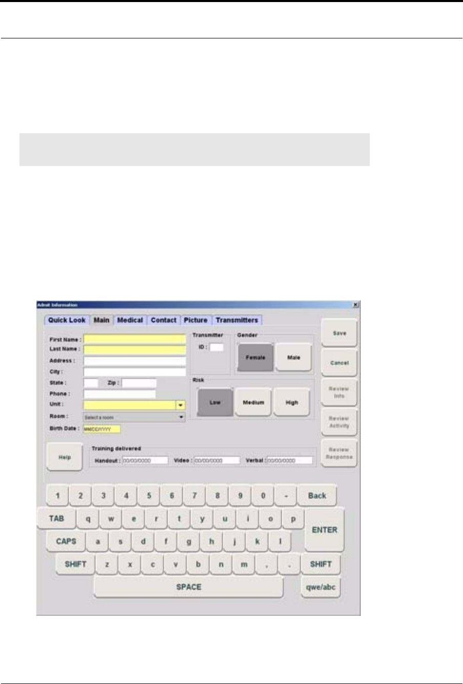
Series 7.0 Software (0510-1086-B) - User Guide 39
Touchscreen Monitor
Touchscreen Monitor
An on-screen keyboard is available to fully utilize the monitor. Simply use the keyboard on the screen as you
would use a keyboard connected to a computer.
To turn On/Off the on-screen keyboard
1. Select Login (or Functions if password protection is disabled).
2. Enter your Login and Password or use your identification card.
3. Select Administrative Functions.
4. Select Change Client Properties.
5. Select Display
6. Select the Display Virtual Keyboard check box.
FIGURE 2.3: On-Screen Keyboard
NOTE: When using the Select Multiple feature, anomalies may occur when using the on-
screen keyboard while the desktop keyboard is connected to the computer.
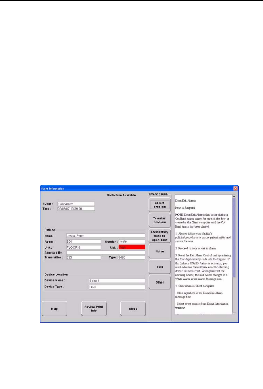
Chapter 2: Software Features
40 Series 7.0 Software (0510-1086-B) - User Guide
Quick Reference Tutorial
A Quick Reference Tutorial is embedded in the software to aid users in responding to alarms. The option to
display the tutorial can be turned off by deselecting the Display Tutorial Help check box.
To deselect the Display Tutorial Help check box
1. Select Login (or Functions if password protection is disabled).
2. Enter your Login and Password or use your identification card.
3. Select Administrative Functions.
4. Select Change Client Properties.
5. Select Display
6. Deselect the Display Tutorial Help check box
The Quick Reference Tutorial opens within the Event Information Window when responding to Red, Blue
and White alarms (refer to the section “Event Information Window” on page 96 for information on Red, Blue
and White alarms). The tutorial contains a quick reference on how to respond to an alarm and common
causes for the alarm.
FIGURE 2.4: Quick Reference Tutorial Window
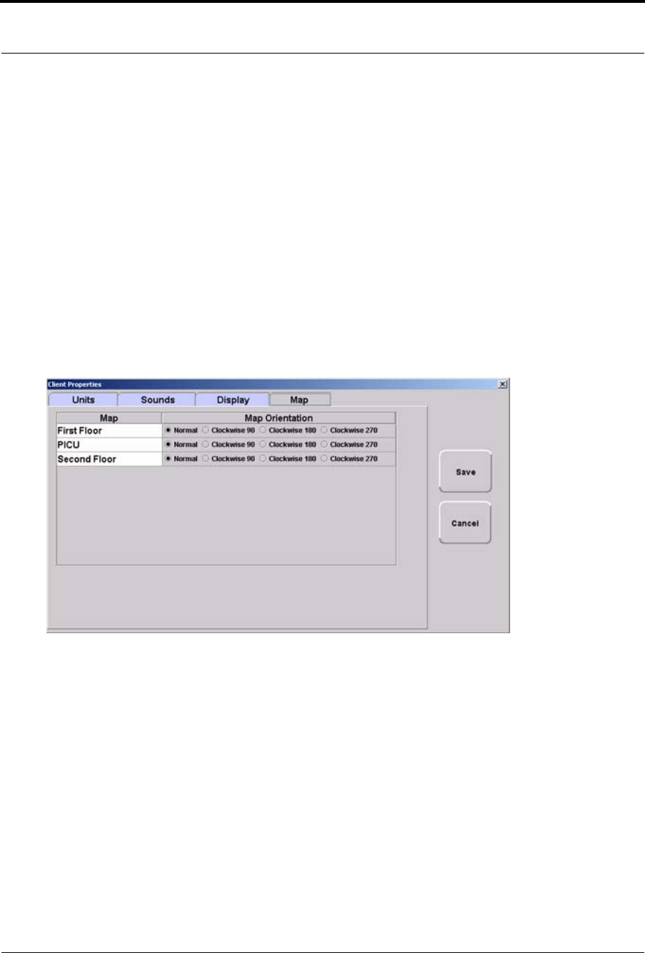
Series 7.0 Software (0510-1086-B) - User Guide 41
Map Orientation
Map Orientation
Maps can be rotated for visual orientation of the unit. Icons distributed on the map represent the location of
each device assigned to the unit. Icons do not move from the their original placement on the map; they rotate
with the map. An indication of where you are, based on the placement of the computer at the time of
configuration, is also displayed on the map.
To rotate the Map displayed on the client computer
1. Select Login (or Functions if password protection is disabled).
2. Enter your Login and Password or use your identification card.
3. Select Administrative Functions.
4. Select Change Client Properties.
5. Select the Map tab.
FIGURE 2.5: Client Properties - Display
6. On the Map tab, select the unit to which you want to rotate the map.
7. Click the radio button next to the Map Orientation that you wish displayed for that unit.
8. Do one of the following:
a. Click Save to save and return to the main window.
b. Click Cancel to return to the main window without saving.

Chapter 2: Software Features
42 Series 7.0 Software (0510-1086-B) - User Guide
Ruleset for Displaying Patient Name
The ruleset for displaying the patient’s name on the Quick Look Display, Pager and in the Alarm Message
Box on the central server and client computer(s) is based on the patient information entered during the admit
process and whether the HIPAA option is enabled in the software (refer to the Series 7.0 Software
Administrator Guide). When HIPAA is enabled, the patient’s name is not shown on the Quick Look Display.
The patient’s first name or last name is required when entering patient information during the admit process.
Depending on what information is entered, the following ruleset applies.
Patient Information What is displayed on the Quick Look Display
First and Last name Last name, First name
Last name only Last name
First name only First name
If HIPAA privacy is enabled Last name-Gender
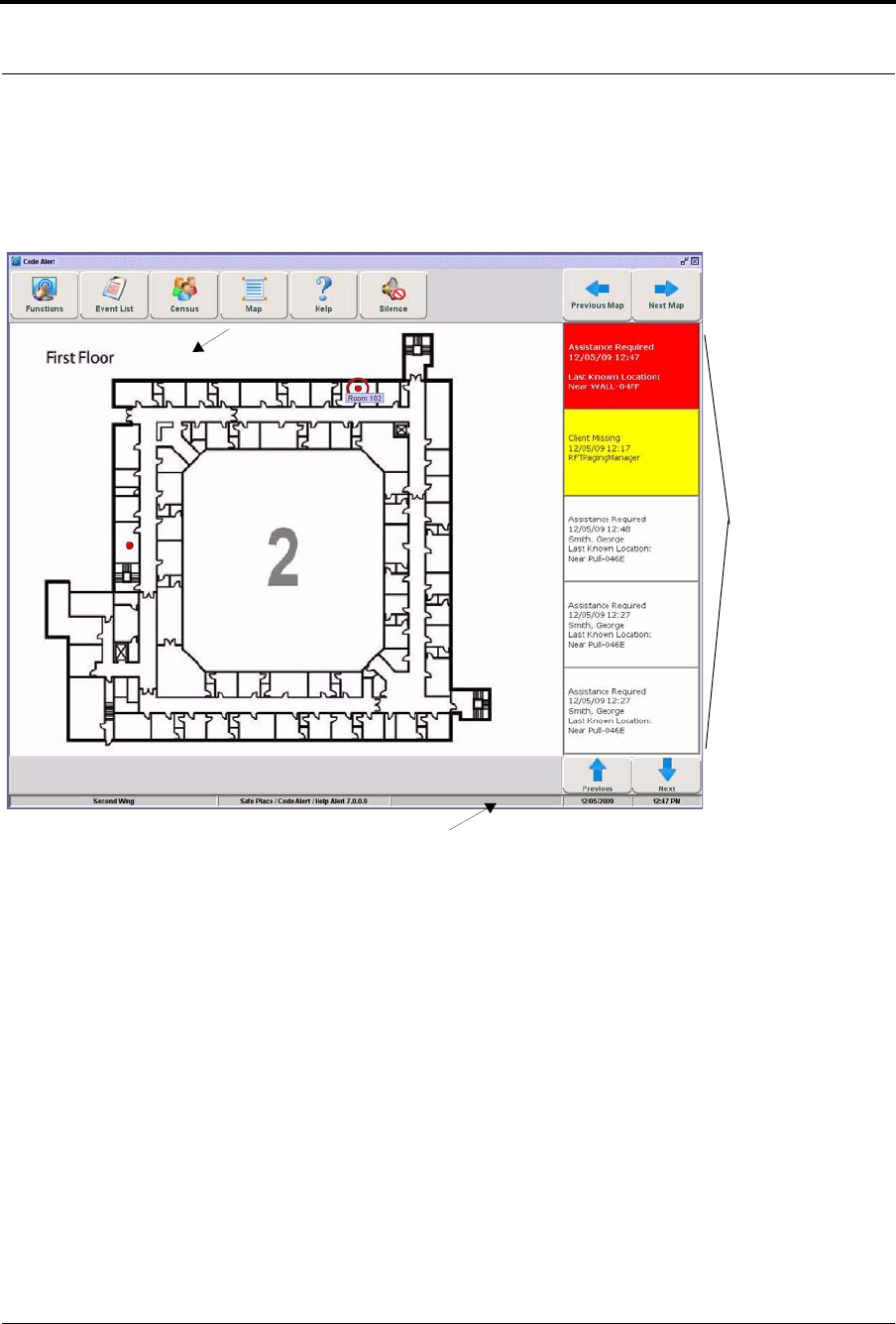
Series 7.0 Software (0510-1086-B) - User Guide 43
The Main Window
The Main Window
When the software is started, the main window appears. It contains all the necessary information to operate
your system.
FIGURE 2.6: Main Window
Menu Bar
Click to open the Low Batteries Report (only appears when there are low batteries currently in the system).
Event
List
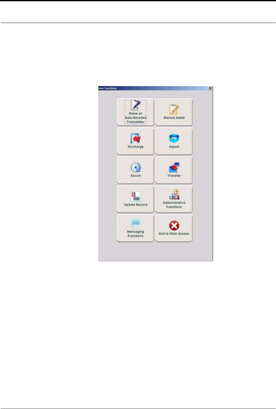
Chapter 2: Software Features
44 Series 7.0 Software (0510-1086-B) - User Guide
Functions
The Functions menu provides access to commonly used functions found in the User Functions menu. The
User Functions available will depend on your software licenses. To access User Functions menu, click
Functions.
FIGURE 2.7: User Functions
NAME AN AUTO-ENROLLED TRANSMITTER—Click to access the Admit Auto-Enrolled
window. This window displays a list of only Auto-Enrolled transmitters. See “Name An Auto-Enrolled
Transmitter” on page 55.
MANUAL ADMIT—Click to access the Admit Information window. This is where you enter a new
patient or asset into the system. This selection is also used to update existing patients or assets. See “Manual
Admit” on page 56.
PRE-ENROLL—Click to access the Pre-Enroll Information window. Alarming band transmitters that are
not banded but are available for use with a proper transmitter number (a Transmitter ID within the range set in
Configuration), can be Pre-Enrolled. See “Pre-Enroll” on page 59.
DISCHARGE—Click to access the Discharge window. This allows you to take a patient or asset out of the
census of monitored transmitters. If the patient is wearing an alarming band transmitter, you then have a
limited time to remove the banding material from the transmitter. The discharge time is configured per unit or
can be set to discharge the patient or asset immediately. See “Discharge” on page 67.
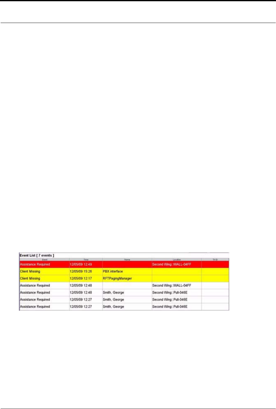
Series 7.0 Software (0510-1086-B) - User Guide 45
Event List
ADJUST—Click to access the Adjust Bands window. This allows you to temporarily suspend the alarm
function for a patient or asset’s alarming band transmitter so the banding material can be readjusted. If there
are no 9450 transmitters configured for the system, this key is disabled. See “Adjust” on page 70.
ESCORT—Click to access the Escort window. This is where you select the amount of time required to take
a patient /asset out of a protected area and back to the same protected unit. See “Escort” on page 73.
TRANSFER—Click to access the Transfer window. This is where you select the amount of time required
to move a patient or asset from one protected area to another protected unit.
UPDATE RECORD—Click to access the Admit Information-Update Record window. This is where
you select a patient to update patient information. See “Update Record” on page 79.
ADMINISTRATIVE FUNCTIONS—Use Administrative Functions to Add/Update Assets, enter Staff
Drill and System Maintenance information, Change Client Properties, access the Configuration options and
access available Reports. See “Administrative Functions” on page 80.
MESSAGING FUNCTIONS—This option allows you to schedule system messages, manage messaging
shifts, and send messages to staff members. See “Messaging Functions” on page 88.
EXIT TO MAIN SCREEN—This option closes the Administrative Function window and returns you to
the Main Screen.
Event List
Click Event List to display all events that are in the system. Clicking on an event takes you directly to that
event’s information window.
FIGURE 2.8: Event List Window
•Click Next to scroll down through events in the list.
•Click Previous to scroll back up through events in the list.

Chapter 2: Software Features
46 Series 7.0 Software (0510-1086-B) - User Guide
Census
Click Census to display a census screen of every Auto-enroll transmitter, patient and asset in the system.
FIGURE 2.9: Census Window
In the top right corner of the Census screen are buttons to allow you to print or scroll through the census.
•Click Print for a print out of the census screen. A printer must be connected to the
computer from which the print command is initiated and set as its default printer.
•Click Next to scroll down through the census.
•Click Previous to scroll back up through the census
The information displayed includes:
Name—the name of the patient, asset or transmitter enrolled in the system.
Room—the room assigned to the patient.
Status—the status (mode of operation) that the transmitter is in (monitor, transfer, escort, adjust, or
discharge).
Last Known Location—the location of the receiver that best picked up the last signal from the transmitter.
Destination—the destination of the patient in escort or transfer.
Time Remaining—the time remaining to complete the escort or transfer.
Transmitter ID—the identification number of the transmitter.
Risk—the risk level assigned to the patient.
Gender—the gender of the patient.
NOTE: The information for State, Last Known Location and Time Remaining only
update every 10 minutes.
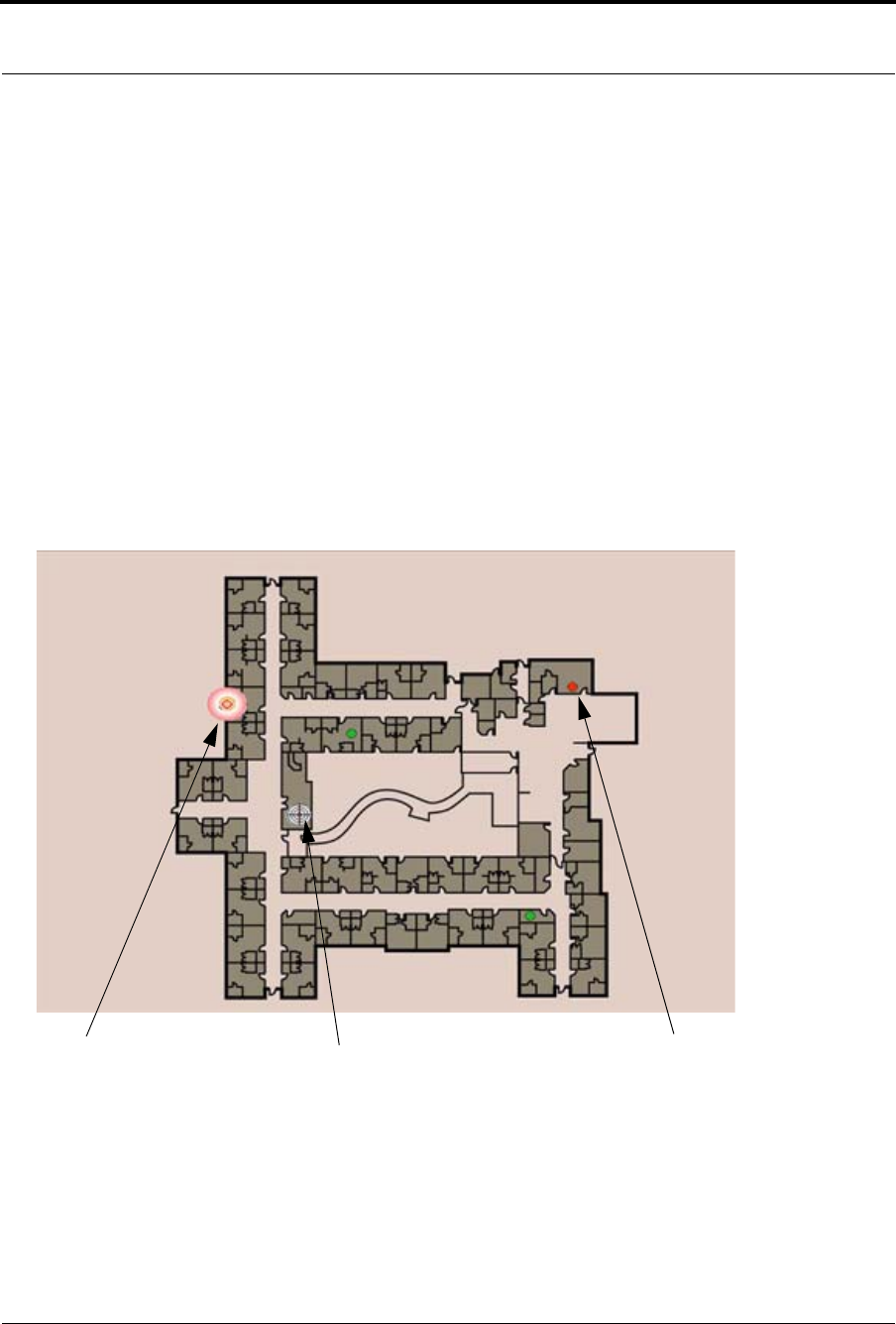
Series 7.0 Software (0510-1086-B) - User Guide 47
Map
Map
Click Map to display a floor plan of each unit the Client computer(s) is configured to monitor. Icons
distributed on the map represent the location of each device assigned to the unit; the icons flash when an
event occurs.
•Click Prev to scroll back to the previous map viewed. Only those maps assigned to the
units monitored on the Client computer(s) are available.
•Click Next to scroll ahead to the next available map. Only those maps assigned to the
units monitored on the Client computer(s) are available.
Devices Displayed on the Map
Devices are displayed on the map or floor plan on the Client computer(s). The display is configured to assist
the staff in monitoring devices. The location of a device issuing an alarm is indicated by a flashing icon on the
map.
FIGURE 2.10: Main Window
You are h ere
Device assigned to a room is in alarm (location of client computer) Flashing icon indicates the location of the
device reporting the event
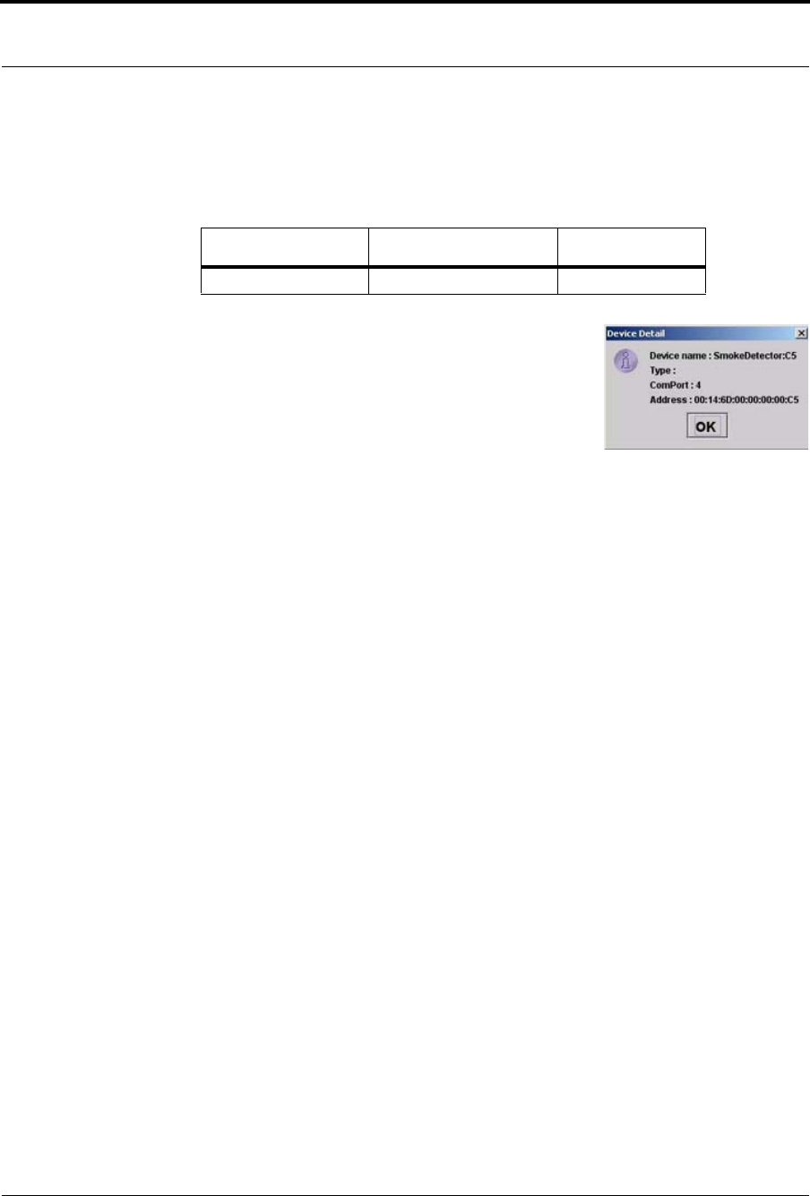
Chapter 2: Software Features
48 Series 7.0 Software (0510-1086-B) - User Guide
If a transmitter location changes, for example if an alarm is activated while the transmitter is in motion, the
receiving device closest to the transmitter triggers the alarm. The icon representing the receiving device
flashes on the Client computer map. Below is a table of how devices are displayed on the map in the Main
Window.
Devices Assigned to a Room
Devices assigned to a room will not show on the map until the room
device goes into alarm. The map will display the room to which the
alarming device is assigned. By clicking on the alarming device icon, you
can bring up details of the device. If more than one device is assigned to a
room, details on both devices are displayed. Click OK to dismiss the
device detail. The icon will continue to flash until the alarm is cleared.
Help
Click Help to access the on-line help window for the Series 7.0 System. Here you can navigating through
user help topics.
Silence
You can click Silence to stop the alarm sound. The alarm is silenced for the configured length of time;
however, the event still appears in the Event List. The next event automatically restarts the alarm sound. This
Silence button is green when the Silence feature is turned ON. To configure the Alarm Silence Time-out,
refer to Series 7.0 Software Administrator Manual.
Normal Mode Alarming Device Fault
Green Flashing Red Flashing Yellow
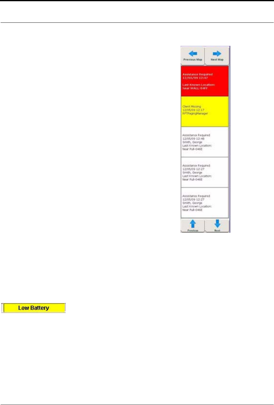
Series 7.0 Software (0510-1086-B) - User Guide 49
Alarm Message Box
Alarm Message Box
From the Map or Census view, click in the alarm message box to access the
Event Information window for that alarm. Alarms are displayed sequentially
as they occur and by priority. Alarms are color coded according to the alarm.
Red Alarm—high priority alarms
Yellow Alarm—medium priority alarms
White Alarm—low priority alarms
Blue Alarm—high priority asset alarms
Light Blue Alarm—low priority asset alarms
•Click Next to scroll down through alarms in the list.
•Click Previous to scroll back up through alarms in the list.
Low Battery Icon
Located on the bottom of the Main Window is a Low Battery icon. The Low Battery icon only appears when
there are transmitters and/or devices with low batteries currently in the system. When visible, the Low
Battery icon appears in yellow.
Click on Low Battery to go directly to the Low Batteries Report.

Chapter 2: Software Features
50 Series 7.0 Software (0510-1086-B) - User Guide
This page intentionally left blank.
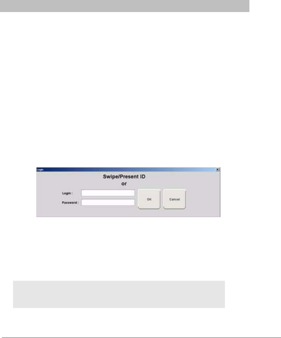
Series 7.0 Software (0510-1086-B) - User Guide 51
Chapter 3
Using the Software
Introduction
This chapter provides detailed information about the Series 7.0 Software functions. For information about
tasks such as adding devices or adding users to a Client computer, see the Series 7.0 Software Administrator
Guide. In addition, for specific information about securing and cleaning alarming band transmitters, see the
appropriate Transmitter User Guide.
Commonly Used Terms
Throughout this guide terms are used to describe functions that may be enabled/disabled in the software or
actions necessary for using the software. Following are commonly used terms and their definitions.
Login and Passwords
Some functions of your system may be password protected. This simply means that a staff member must
enter a login and password or use his or her proximity card or magnetic/barcode card before performing a
task. When you select a function that requires a password, the Login and Password dialog box appears.
To access a password protected function
1. Enter your login name in the Login box.
2. Enter your password in the Password box.
3. Press Enter or click OK.
4. If enabled, use your proximity card or magnetic/barcode card approved for use with the software.
NOTE: The Login, Password and Swipe Card information is case sensitive. If a “User
not Authorized to perform this function” error message occurs, try turning off the Caps
Lock on your keyboard.

Chapter 3: Using the Software
52 Series 7.0 Software (0510-1086-B) - User Guide
Device Supervision
The Supervision feature applies to many devices such as the alarming band transmitters, Pendants, Fall
Monitoring and Incontinence devices. A supervised device is the system’s way of ensuring that devices are
communicating properly and within range of the receivers. When the Supervised transmitter function is
enabled, a No Signal alarm will be posted in the Event List if the system does not receive a signal from the
device within a specified time interval. The supervision interval is configured in the Configuration-Units
menu. The Supervision function defaults ON.
Inactivity Check-in
An Inactivity Check-in is when the system generates an event when no check-in is received or activity is
detected within the selected period of time. This feature is commonly used with Check-in Pull Cords but can
also be used with a PIR Sensor. If the PIR Sensor does not detect motion within the check-in time period, the
system generates an Assistance Required alarm.
The Inactivity Check-in feature is enabled during the Admit process under the Transmitter tab. Inactivity
Check-in devices must first be assigned to a room/and or unit at the Configuration level (refer to the Series
7.0 Software Administrator Guide).
Units
Upon admission, a patient or asset must be assigned to a Unit. A Unit represents a protected area in your
facility that is monitored as a unit, such as the Nursery or Intensive Care. All devices in the area are assigned
to the unit, and are identified on a map or floor plan specific to the unit.
Some units may have more than one patient or asset occupying the same room. It is important when
admitting a patient or asset to a double-occupancy room that you specify which bed or side of the room the
patient or asset is assigned, for example room 101-A or room 101-B.
If an alarm occurs, the relevant alarm information, such as the patient’s or asset’s name, the type of event, and
the location of the event, is displayed at any Client computer that has been configured to monitor the unit.
Some System Properties, such as the time allowed for the discharge and adjust function, are defined at the
unit level.

Series 7.0 Software (0510-1086-B) - User Guide 53
Commonly Used Terms
Global Lockdown
A Global Lockdown is when all of the doors are automatically locked during a Cut Band or Band Off alarm.
If a door is already open at the time a Cut Band or Band Off alarm occurs or if a door is opened at any time
while the system is in Global Lockdown:
•an alarm sounds at the Exit Alarm Controller
•a message is displayed on the Client computer(s) in the unit configured to monitor the
door and on all Quick Look Displays for that unit
•the location of the Exit Alarm is indicated by a flashing icon on the map on the Client
computer(s)
If your facility has enabled the Lockdown on Cut Band Alarms or Lockdown on Band Off Alarms feature, a
Cut Band Alarm or Band Off triggers a Global Lockdown. You can configure the Global Lockdown feature
to lock doors at All exits or By transmitter units. However if a Cut Band or Band Off alarm is triggered during
an Escort or a Transfer, the system automatically locks All exits and posts the alarms on all Client
computer(s). This is because the transmitter in Escort or Transfer may be outside of its protected unit.
NOTE: When a transmitter is configured as a low priority asset transmitter, a Cut Band
Alarm will not trigger a Global Lockdown. High Priority configured asset transmitters
will trigger a Global Lockdown.
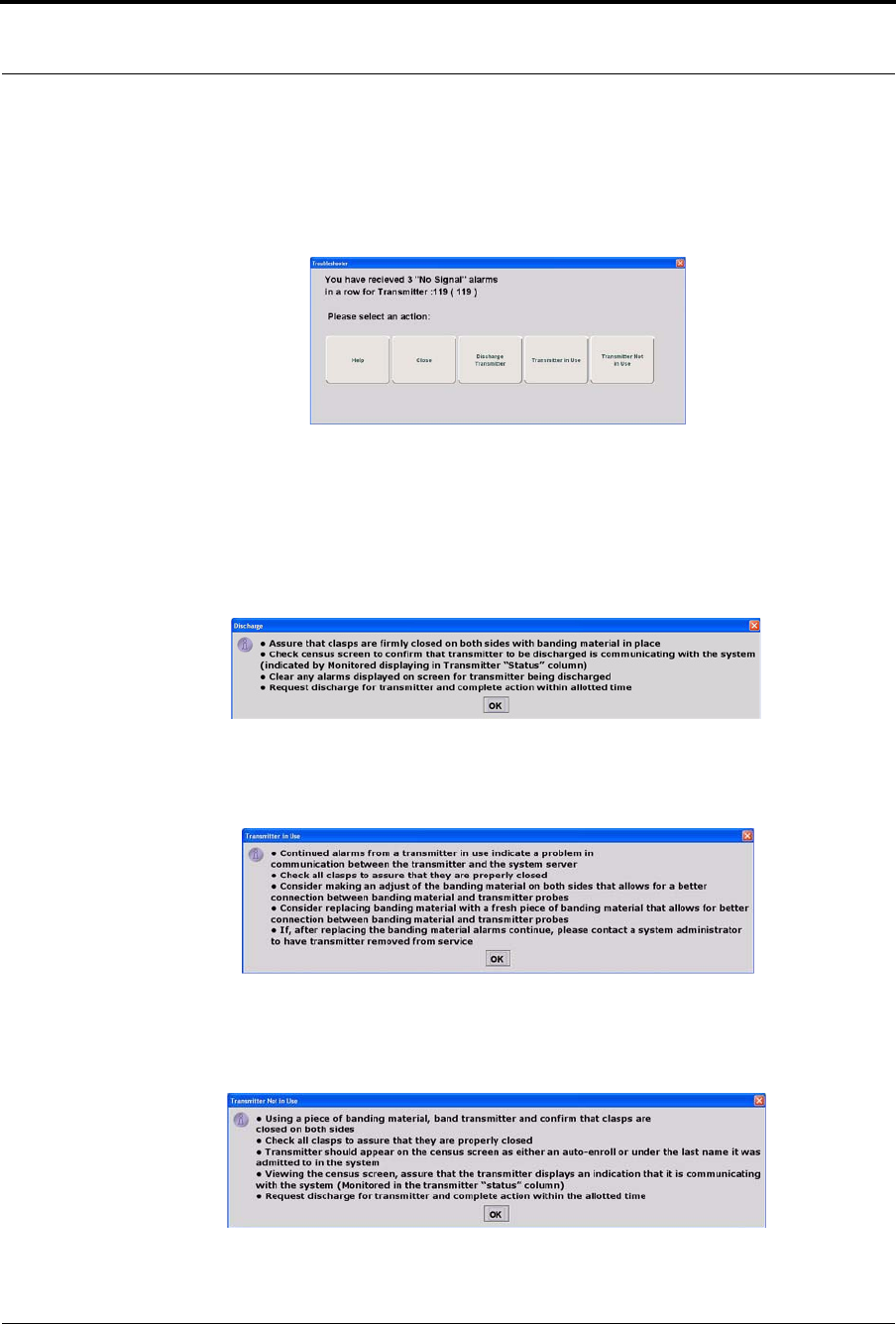
Chapter 3: Using the Software
54 Series 7.0 Software (0510-1086-B) - User Guide
Troubleshooter
A Troubleshooter dialog box appears after three consecutive No Signal alarms are received and the user
clicks in the Alarm Message box for that alarm.
How to respond to Troubleshooter
1. Click Help to open a Help window.
2. Click Close to close the Troubleshooter and open the Event Information window allowing you to
select an Event Cause for the alarm.
3. Click Discharge to open the following information dialog.
4. Click OK. The Event Information window opens allowing you to select an Event Cause for the
alarm.
5. Click Transmitter In Use to open the following information dialog.
6. Click OK. The Event Information window opens allowing you to select an Event Cause for the
alarm.
7. Click Transmitter Not In Use to open the following information dialog.
8. Click OK. The Event Information window opens allowing you to select an Event Cause for the
alarm.
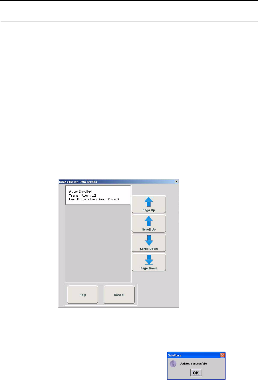
Series 7.0 Software (0510-1086-B) - User Guide 55
Admit Functions
Admit Functions
Admit Functions such as Name An Auto-Enrolled Transmitter and Manual Admit are found in the User
Functions menu. To Add/Update An Asset is found in the second tier of the User Functions menu under
Administrative Functions.
Name An Auto-Enrolled Transmitter
Transmitters that are automatically enrolled in the system can be assigned to a patient using this option. When
you click on a window opens with only Auto-Enrolled transmitters.
To admit a patient from Name An Auto-Enrolled Transmitter
1. Select Login (or Functions if password protection is disabled).
2. Enter your Login and Password or use your identification card.
3. Click Name An Auto-Enrolled Transmitter.
The Admit Selection - Auto-Enrolled window appears. Auto-enrolled transmitters that currently
exist in the census are listed in the window.
FIGURE 3.1: Admit Selection –Auto Enrolled
4. Use the arrow buttons to find and select the transmitter number to be assigned.
5. Double click on the Auto-Enrolled transmitter to bring up the Admit Information window and enter
admit information; the yellow fields designate required entry
6. Once admit information has been entered, click Save.
If the admit is successful, you will get the following dialog box:
7. Click OK.
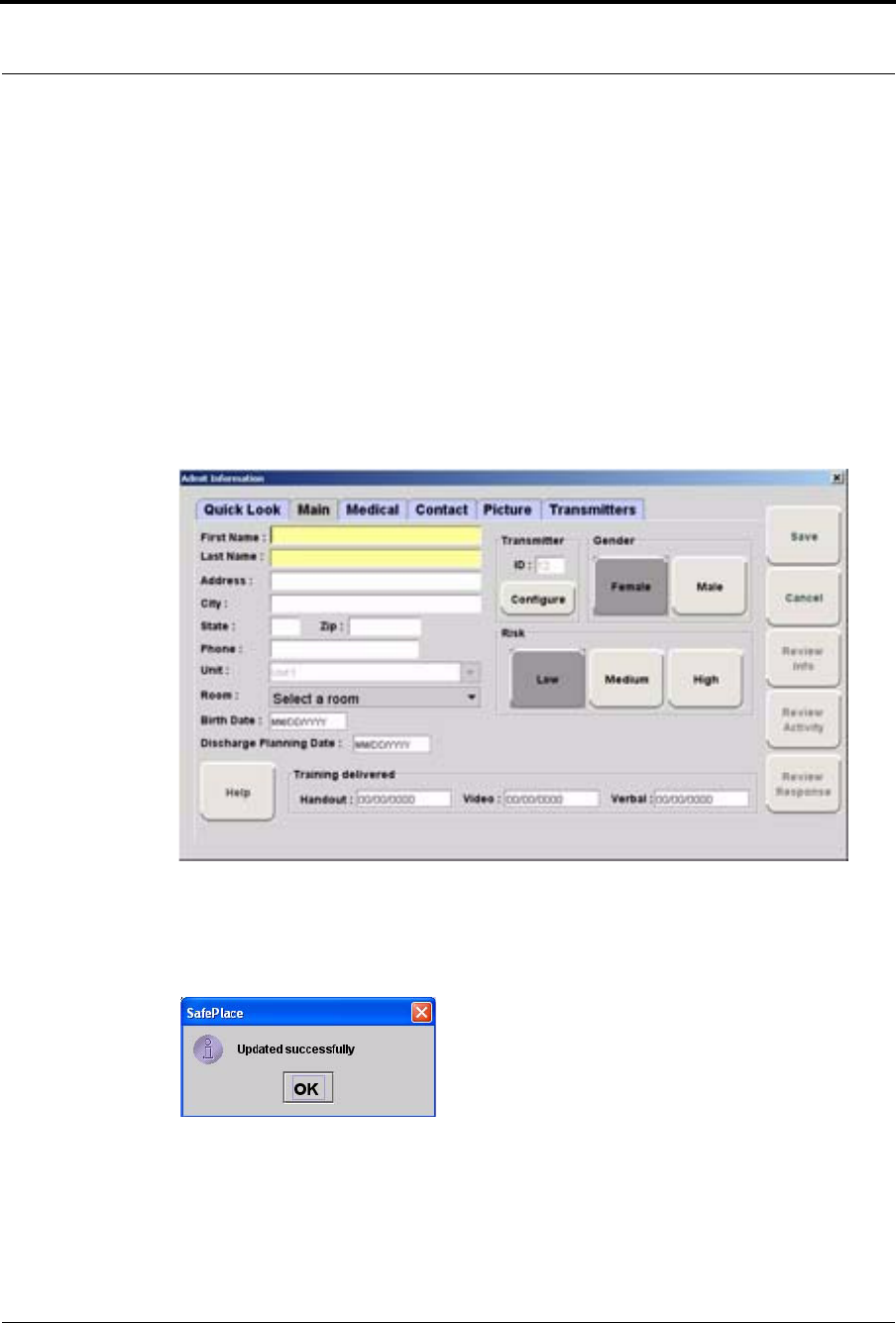
Chapter 3: Using the Software
56 Series 7.0 Software (0510-1086-B) - User Guide
Manual Admit
Using the Manual Admit function, you can admit a patient and enable the system to associate the transmitter
with information of the patient being admitted.
To admit a patient from the Manual Admit button
1. Select Login (or Functions if password protection is disabled).
2. Enter your Login and Password or use your identification card.
3. Click Manual Admit.
4. The Admit Information window opens for you to enter admit information; the yellow fields
designate required entry.
FIGURE 3.2: Admit Information
5. Once admit information has been entered, click Save.
If the admit is successful, you will get the following dialog box:
6. Click OK.
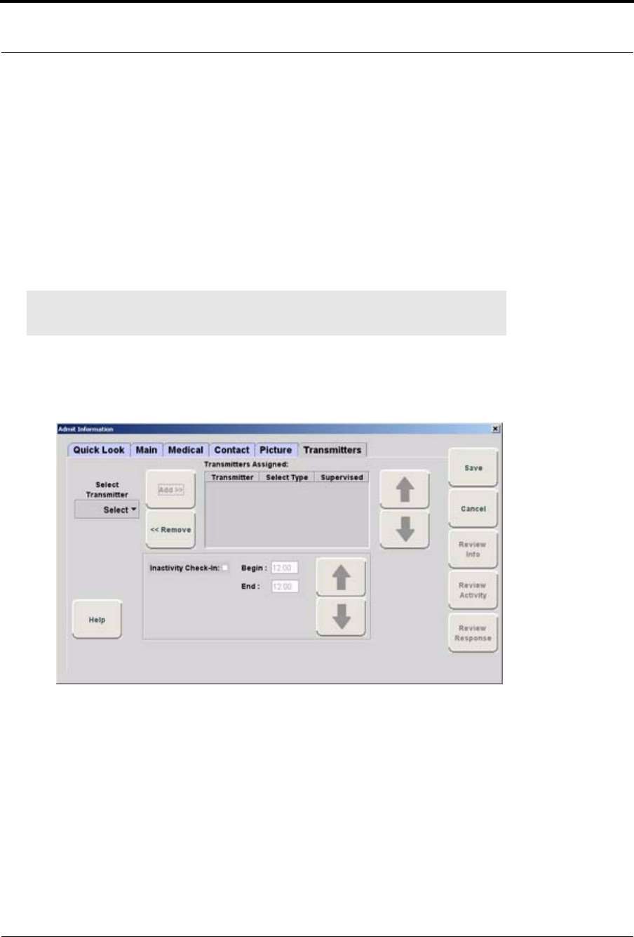
Series 7.0 Software (0510-1086-B) - User Guide 57
Admit Functions
To admit with a Pendant, Fall Monitoring or Incontinence device
1. Alarm then reset the device.
2. Select Login (or Functions if password protection is disabled).
3. Enter your Login and Password or use your identification card.
4. Click Manual Admit.
The Admit Selection window appears.
5. Enter patient information; the yellow fields designate required entry.
6. Select the Transmitter tab.
7. Select the Transmitter ID number (printed on Pendant) from the pull-down.
8. Click Add
The Admit Information window appears allowing you to select the transmitter type.
FIGURE 3.3: Admit Information to Select Transmitter Type
9. Select the Transmitter Type from the pull-down menu.
•Pendant
•Fall Monitoring
•Incontinence
10. For a QR transmitter the Supervised option is selected by default. If desired, deselect it.
NOTE: The Transmitter tab will not appear until a QR Transmitter ID Range is
configured into the system (refer to the Series 7.0 Software Administration Guide).
Chapter 3: Using the Software
58 Series 7.0 Software (0510-1086-B) - User Guide
11. For an 9600 Series transceiver the Supervised time defaults to the unit’s Transmitter Supervise
Time, set during configuration. However, you can select a different time from the drop-down list.
12. Select SAVE.
If the admit is successful, you will get the following dialog box:
13. Click OK.
For more information on the Transmitter tab, refer to “Enter Transmitter Information” on page 64.
To admit with a fixed device
1. Select Login (or Functions if password protection is disabled).
2. Enter your Login and Password or use your identification card.
3. Click Manual Admit.
The Admit Information window appears.
4. Enter patient information; the yellow fields designate required entry.
5. Select the Room that was configured with device from the drop-down menu.
6. Click Save.
NOTE: To ensure supervision configuration changes are accepted by the Pendant
transceiver, it is important to alarm the Pendant after a change in device configuration.
NOTE: Pull Cords and Smoke Detectors are considered fixed devices. They are assigned
to a room and/or unit at the Configuration level. Refer to the Series 7.0 Software
Administrator Guide.
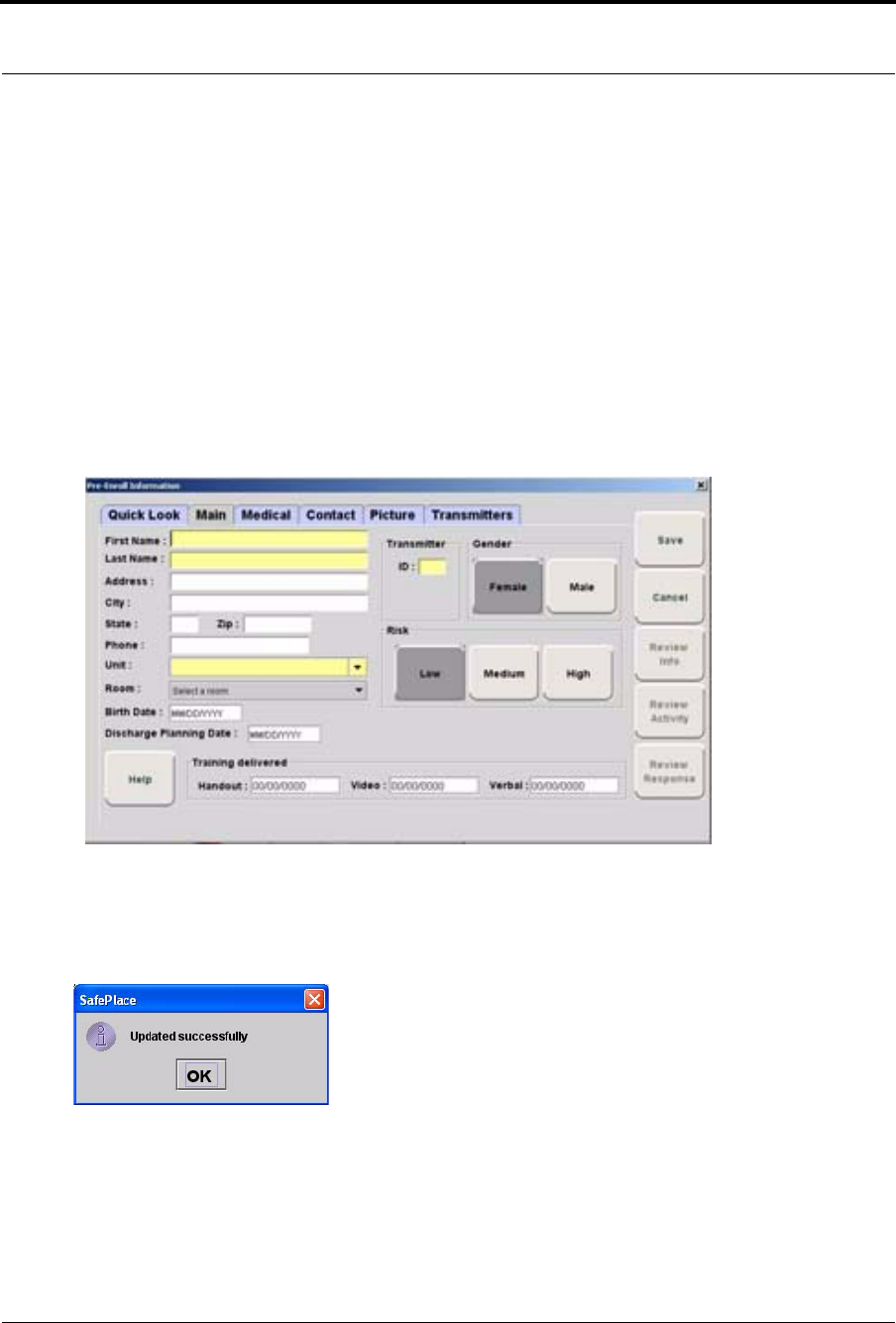
Series 7.0 Software (0510-1086-B) - User Guide 59
Admit Functions
Pre-Enroll
Alarming band transmitters that are not banded but are available for use with a proper transmitter number (a
Transmitter ID within the range set in Configuration), can be pre-enrolled.
To Pre-Enroll a transmitter
1. Select Login (or Functions if password protection is disabled).
2. Enter your Login and Password or use your identification card.
3. Click Pre-Enroll.
4. The Pre-Enroll Information window opens for you to enter admit information; the yellow fields
designate required entry.
FIGURE 3.4: Pre-Enroll Information
5. Once admit information has been entered, click Save.
If the admit is successful, you will get the following dialog box:
6. Click OK.
7. The Pre-Enroll transmitter appears in the Census with a status of Pre-Enroll. The transmitter must
be banded within the time set in Configuration. A white Pre-Enroll Expired alarm message is
generated if the time expires before banding. You must Clear the alarm and Pre-Enroll the
transmitter again, making sure that it is properly banded within the configured time.
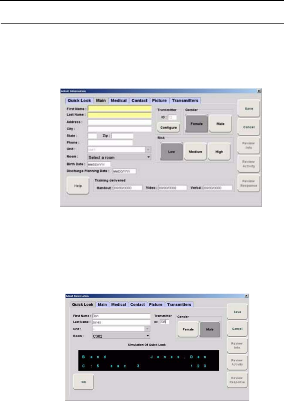
Chapter 3: Using the Software
60 Series 7.0 Software (0510-1086-B) - User Guide
Admit Information Windows
From the Admit Information window you can enter the general information about the patient being admitted.
The yellow fields designate required entry. There are six tabs for entering patient admit information and one
for Scheduling Events (see “Scheduling an Event” on page 65).
FIGURE 3.5: Admit Information Window
Admit Information Tabs
Quick Look Tab
The Quick Look tab allow users to see the what entered patient information will look like on a simulated
Quick Look. The fields are subject to the same rules for truncation currently used for the Quick Look
Display.
FIGURE 3.6: Quick Look Tab

Series 7.0 Software (0510-1086-B) - User Guide 61
Admit Information Windows
Main Tab
The Main information tab allows you to enter general information about the patient being admitted; the
yellow fields designate required entry. Depending on your configuration, the Birth Date field may be a
required entry for the Series 7.0 Software. When updating admit information for patients who were enrolled
in the system prior to software version 7.0, you must enter the patient’s birth date even if that information
was not previously entered.
1. Click the Main tab.
2. In the First Name box, type the first name of the patient being admitted (either first or last name is
required).
3. In the Last Name box, type the last name of the patient being admitted (either first or last name is
required).
4. Type the patient’s Address, City, State, Zip.
5. In the Phone field, type the phone number of the patient.
6. In the Unit field, select the unit to which the patient is currently assigned, even if the patient will not
remain in that unit (required).
7. In the Room field, select the patient’s room number.
8. In the Birth Date field, enter the patient’s birthday (two digit month, two digit day, four digit year).
9. Click Female or Male to indicate the gender of the patient.
10. In the Discharge Planning Date field, enter the planned date of discharge (the appearance of this
field depends on your system configuration)
11. In the Training Delivered field, indicate the type of training material used by entering the date
training was delivered to the patient or patient’s family.
12. In the Transmitter ID field, type the 3-digit ID number printed on the transmitter to be assigned to
the patient.
13. Click Configure to configure the Band Off settings for the transmitter. (See “Configure Band Off”
on page 62.)
14. Click the Risk level for abduction or elopement associated with the patient. Choices are Low,
Medium or High.
NOTE: Information entered can only contain alphabetic and numeric characters, spaces,
and the following special characters: ! - _ , . ; [ ]{ }( )
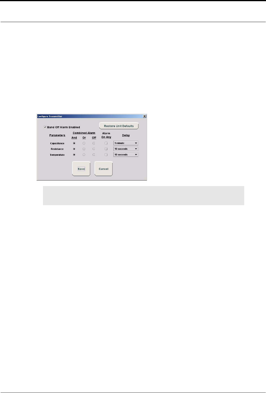
Chapter 3: Using the Software
62 Series 7.0 Software (0510-1086-B) - User Guide
Configure Band Off
The default Band Off settings are configured at the Unit Properties level (refer to Configure Units in the
Series 7.0 Administrator Manual). However, the default settings for Band Off can be changed for each
transmitter being admitted using the Configure option.
To configure the Band Off settings
1. Click the Configure button on the Main Tab of the Admit screen.
The Configure Transmitter window opens.
2. Click the Band Off Alarm Enabled checkbox to enable/disable the Band Off feature for the
transmitter being admitted.
3. To restore the Unit’s current defaults, click the Restore Unit Defaults button.
4. To change a transmitter’s settings for generating a Band Off alarm, select any valid combination of
Combined Alarm radio buttons and the Alarm on Any checkboxes. From the Combined Alarm,
each parameter must have a value of And, Or, or Off.
a. Click the And radio button next to a parameter to select it as “one” of the required parameters
for a Band Off alarm. At least one other parameter must be set to And to generate a Band Off
alarm (i.e. Capacitance and Resistance). You can also select And for one parameter and Or
for at least two other parameters to generate a Band Off alarm (i.e. Temperature and
Capacitance or Resistance).
b. Click the Or radio button next to a parameter to select it as “one” of the required parameters
for a Band Off alarm. At least one other parameter must be set to Or to generate a Band Off
alarm (i.e.Resistance or Temperature).
c. Click the OFF radio button next to a parameter to select it as a parameter that will not be used
for determining a Band Off alarm.
5. Click the Alarm On Any check box next to a parameter to individually choose it to generate a
Band Off alarm.
6. The Band Off Delay settings can also be changed for each parameter. Once a Band Off condition
is met, the alarm will be delayed for the configured time. If the Band Off condition resolves within
the delayed time, the Band Off alarm will not be sent. For Combined Alarms, the parameter with
the longest delay takes precedence.
NOTE: The Configure button will not be present if Band Off alarms are not enabled for the
currently assigned unit.
Parameters:
•Capacitance—the change in contact between
transmitter and infant’s extremity
•Resistance—the stretch of the banding material
•Temperature—the change in transmitter
temperature

Series 7.0 Software (0510-1086-B) - User Guide 63
Admit Information Windows
Medical Tab
The Medical information tab is only accessible from the Patient Admit Information window. To access the
Medical Info tab, the user must be a configured into the system as a Care Provider (refer to the Series 7.0
Software Administrator Guide).
The Medical Info tab allows you to enter medical information about the patient being admitted. Fields are
provided here for you to enter information necessary per your facility’s policies and procedures.
Contact Tab
The Contact information tab allows you to enter contact information about the patient or asset being admitted.
1. Click the Contact tab.
2. In the Special Instructions field, type any special instructions associated with the patient or asset.
3. In the Name field, type the name of the primary contact for inquires regarding the patient or asset.
4. In the Phone field, type the phone number of the primary contact.
5. Type the Address, City, State, Zip of the primary contact.
If there is more than one contact, you can enter that information in the subsequent contact fields.
Insert a Picture
The Picture tab allows you to insert a picture of the patient or asset being admitted. The patient’s picture is
displayed on patient generated reports. When available, the patient’s picture also appears in the Event
Information window for Cut Band, Door, and No Signal alarms as well as alarms generated from Pendant,
Fall Monitoring and Incontinence devices.
All of the pictures in the system are stored on the P: drive on the Server. When you need to enter a picture for
a patient, go to the P: drive.
1. To insert a picture, click or press the (...Browse) button.
2. Select a picture from the Browse Picture Files dialog box.
NOTE: Information entered can only contain alphabetic and numeric characters, spaces,
and the following special characters:! - _ , . ; [ ]{ }( )
NOTE: Information entered can only contain alphabetic and numeric characters, spaces,
and the following special characters: ! - _ , . ; [ ]{ }( )
IMPORTANT: All pictures must be placed in the P: directory. If you are using a digital
camera, removable USB drive, or any other removable media, you must first save the
picture file to the P: directory before removing the media.
It is the responsibility of the customer to have the system work on their domain which
governs the security access to their network.

Chapter 3: Using the Software
64 Series 7.0 Software (0510-1086-B) - User Guide
To save a picture to the P: drive on the Server
1. Insert the removable media (USB drive).
2. On the Computer Desktop, double-click My Computer.
3. Double-click the removable media.
4. Right-click the pictures on the media you want to access and select Copy.
5. Double-click P:.
6. Double-click Pictures.
7. Double-click Patient or Asset.
8. Right-click and select Paste to paste the pictures to the P: drive for access.
Enter Transmitter Information
The Transmitters tab is only accessible from the Patient Admit Information window. The Transmitter tab
allows you to enter Pendant, Fall Monitoring and Incontinence transmitter information of the patient being
admitted.
To enter transmitter information of the patient being admitted:
1. Click the Transmitters tab.
2. Select the patient’s transmitter number in the Transmitter ID: field.
3. Click Add.
4. From the Transmitter Assigned field, select the transmitter type.
5. For a QR transmitter the Supervised option is selected by default. If desired, deselect it.
6. For an 9600 Series transceiver the Supervised time defaults to the unit’s Transmitter Supervise
Time, set during configuration. However, you can select a different time from the drop-down list.
7. If you want to enable the Inactivity Check-In feature for the transmitters, select the check box.
8. Enter the Begin and the End times for the Inactivity Check-In.
9. Click Save.
NOTE: Information entered can only contain alphabetic and numeric characters, spaces,
and the following special characters: ! - _ , . ; [ ]{ }( )
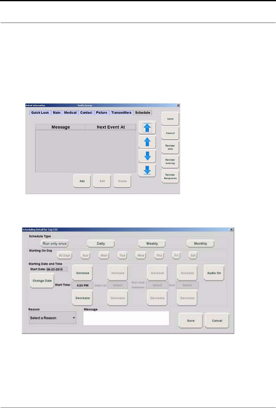
Series 7.0 Software (0510-1086-B) - User Guide 65
Admit Information Windows
Scheduling an Event
The Schedule tab is only accessible for patients already admitted to the system. The Schedule tab allows you
to schedule one time only, daily, weekly or monthly activities (events) to alarm on a per patient basis.
To schedule an event:
1. Click on the Schedule tab to open the following window.
FIGURE 3.7: Schedule Tab
2. Click Add to open the Scheduling Detail window for adding events.
FIGURE 3.8: Schedule Detail window
3. Select the Schedule Type. Do you want the scheduled event to:
•Run only once
•Daily
•Weekly
•Monthly
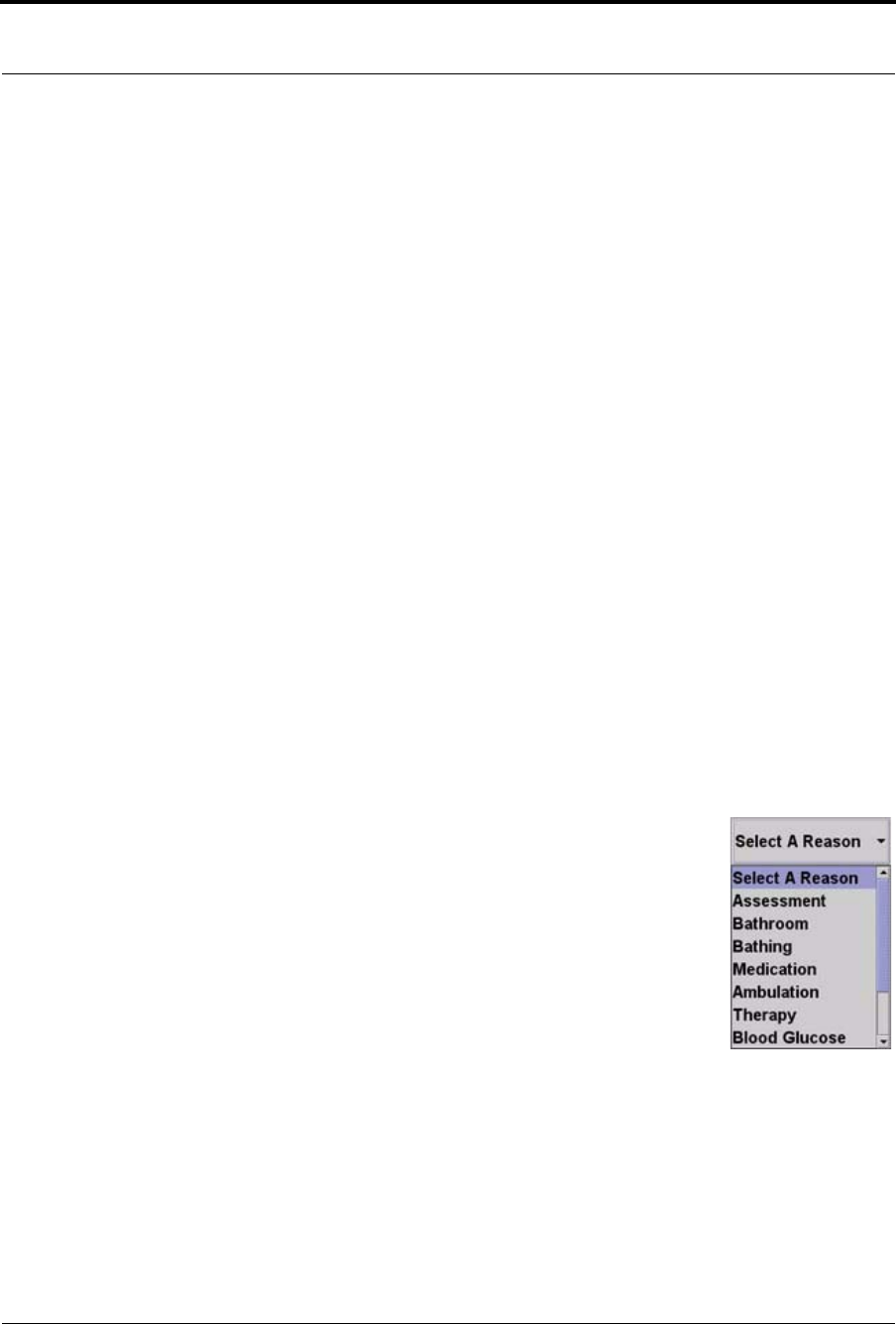
Chapter 3: Using the Software
66 Series 7.0 Software (0510-1086-B) - User Guide
4. If you choose to run the scheduled event daily, you must select the day(s) you wish to run the event.
Choose the day(s) from the Starting On Day field.
5. From the Starting Date and Time field, select a date and time to start the scheduled event. The
current date is displayed in the Start Date field. To change the date, click on Change Date and
choose a date from the popup calendar.
6. Choose a Start Time. The current time is displayed, click Increase or Decrease to select the
desired start time.
7. If you choose to run the scheduled event more than once daily, you must select a run Interval and
Run only between times. The Interval is how often you want the scheduled event to run.
Increments are 1 minute (0:01) to 11 hours and 59 minutes (11:59). Click Increase or Decrease to
select interval.
8. The Run only between range can be set for any minute of the day. Click Increase or Decrease to
select the starting Run only between time AND click Increase or Decrease to select the ending
Run only between time.
NOTES:
•The scheduled event Start Time must fall within the starting Run only between
time and the ending Run only between time range. For example, a scheduled event
with a start time of 8:00 A.M. must have a Run only between time window that
includes 8:00 A.M. A Run only between time of 7:00 A.M to 10:00 A.M. is
legitimate; it includes 8:00 A.M. A time of 4:00 A.M. to 7:00 A.M. is not a
legitimate Run only between time.
•The scheduled event’s Interval time must be less than the time window created by
the Run only between times. For example, a scheduled event with an interval of 5
hours must have a Run only between time window of at least 6 hours.
9. The Audio button toggles On/Off. When Audio is turned On, the
scheduled event will alarm at the Client computer(s).
10. Select a reason for the scheduled event from the Select A Reason pull
down or enter free text in the Message field.
11. Click Save to save your changes or Cancel if you do not wish save your
changes.
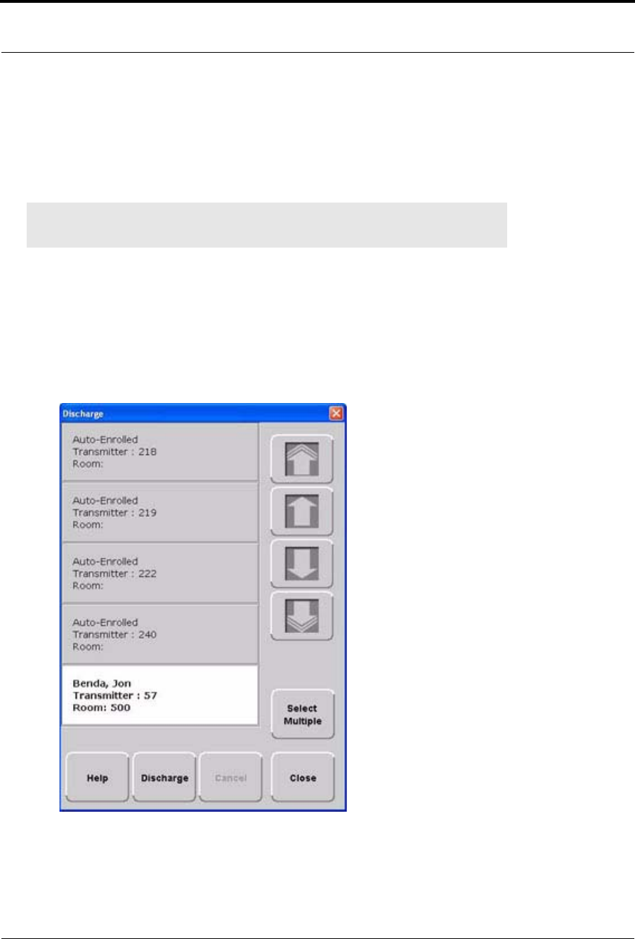
Series 7.0 Software (0510-1086-B) - User Guide 67
Discharge
Discharge
When it is time for a patient to leave your facility, he/she must be discharged from the software. If applicable,
the alarming band transmitter is removed from the patient within the period of time specified in the software
by your facility. Finally, the transmitter must be disinfected in order to be ready to be used again.
To discharge a patient or asset
1. Select Login (or Functions if password protection is disabled).
2. Enter your Login and Password or use your identification card.
3. Click Discharge.
The Discharge window appears. Patients, assets or Auto-Enrolled transmitters that currently exist
in the census are listed in the window.
FIGURE 3.9: Discharge Window
NOTE: If a transmitter is in alarm, the event must be cleared before the patient or asset
can be discharged.
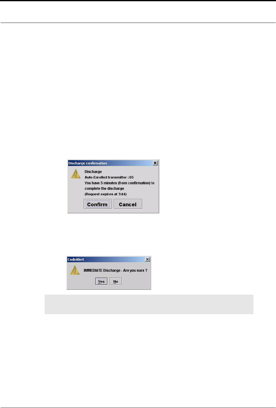
Chapter 3: Using the Software
68 Series 7.0 Software (0510-1086-B) - User Guide
4. Use the arrow buttons to find and select the patient or asset to be discharged. Multiple patients or
asset can be selected for discharge.
a. Hold down the Ctrl key on the keyboard or, if the virtual keyboard is activated, click on the
Select Multiple button in the Discharge window. The Select Multiple button highlights
when activated.
b. Select the patients or assets to be discharged.
5. Click Discharge.
a. If the discharge is for a Wander Management transmitter, Pendant, Fall Monitoring or
Incontinence device, the discharge occurs immediately.
b. If the discharge is for an alarming band transmitter, a dialog box appears showing the patient’s
or asset’s name and the amount of time you have to remove the banding material from the
transmitter. The amount of time you have to remove the banding material can be set in the
Configuration, Units menu (refer to the Series 7.0 Software Administrator Guide).
Click Confirm to confirm the Discharge.
Click Cancel or X to cancel the Discharge request and close the window.
c. If the amount of time for discharge is set to immediate, a dialog box appears asking you if you
are sure you want to discharge the patient or asset.
6. Click Yes.
7. Remove the alarming band transmitter from the patient or asset within the time allowed; the
patient’s or asset’s name is automatically removed from the census.
NOTE: You cannot discharge a patient or asset that is not in the unit being monitored by
the Client computer you are currently using.
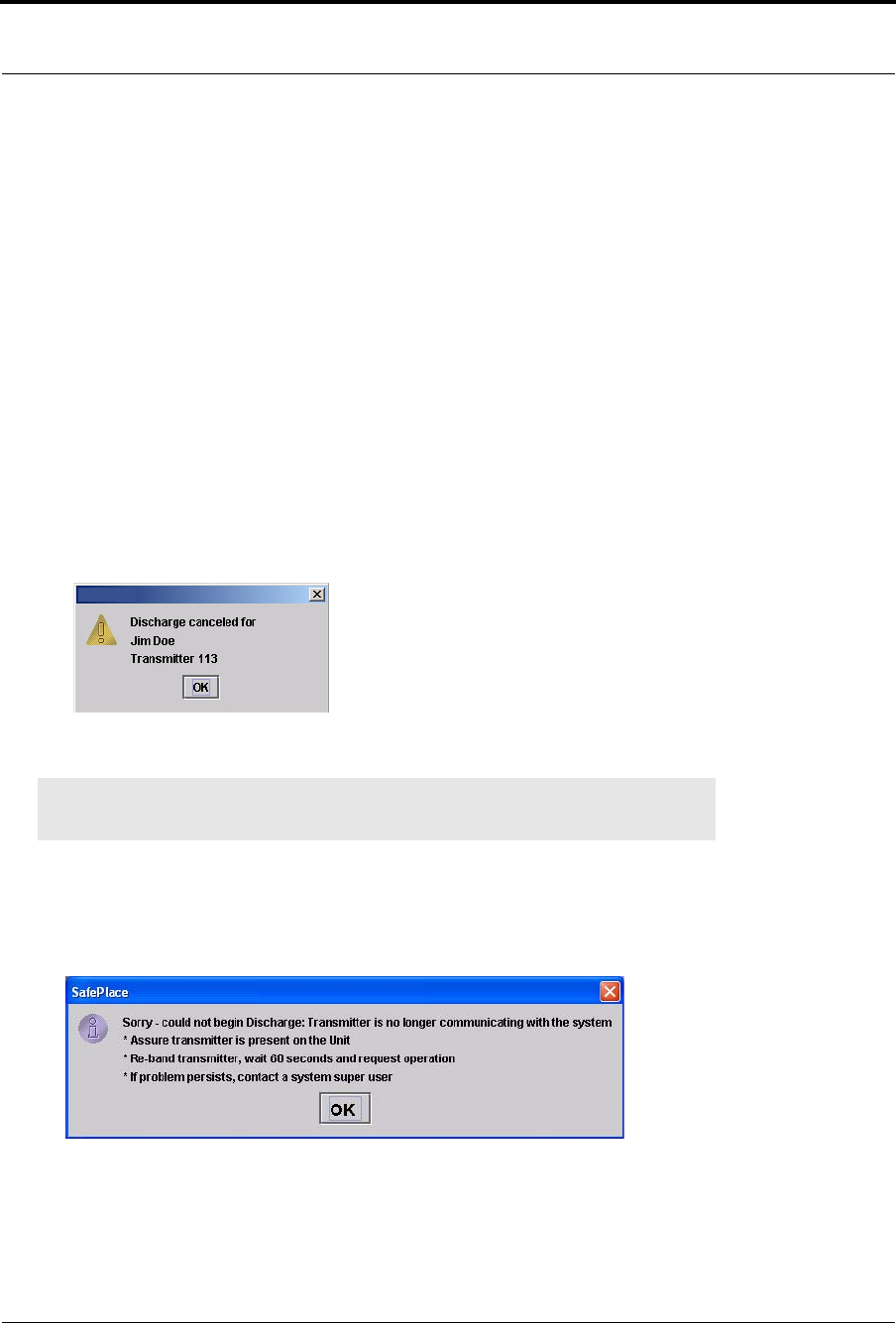
Series 7.0 Software (0510-1086-B) - User Guide 69
Discharge
To cancel a discharge
If the discharge is for an alarming band transmitter, you can cancel the discharge before the discharge time
expires.
1. Select Login (or Functions if password protection is disabled).
2. Enter your Login and Password or use your identification card.
3. Click Discharge.
The Discharge window appears (Figure 3.9 on page 67). Patients, assets or auto-enrolled
transmitters that currently exist in the census are listed in the window.
4. Use the arrow buttons to find and select the patient or asset whose discharge is to be canceled.
Multiple patients or asset can be selected for canceling.
5. Click Cancel.
A dialog box appears indicating that the discharge for the selected patient or asset has been
canceled.
6. Click OK.
Transmitter is no longer communicating with the system
The following dialog box appears when a transmitter is no longer communicating with the system and a
Discharge attempt is made.
1. Follow the steps outline in the dialog box.
2. Click OK.
NOTE: If the unit is configured for immediate discharge, you will be unable to cancel the
discharge.
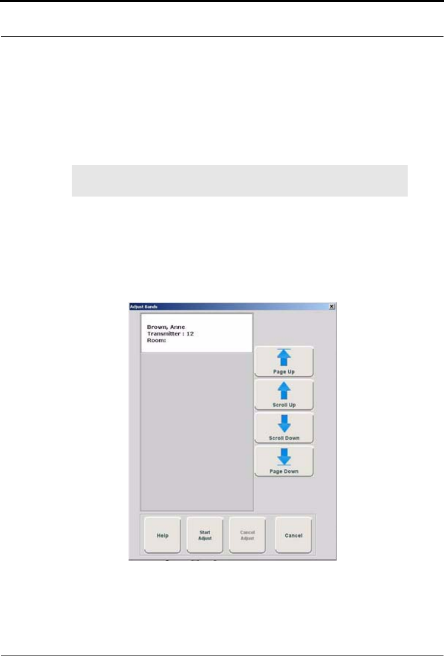
Chapter 3: Using the Software
70 Series 7.0 Software (0510-1086-B) - User Guide
Adjust
The Adjust feature is only applicable with alarming band transmitters. In the normal course of a patient’s stay
in your facility, it may become necessary to adjust the banding material so that the alarming band transmitter
fits the patient’s ankle or wrist more comfortably and securely. The Adjust function temporarily suspends the
Cut Band feature for a selected transmitter, allowing the banding material to be adjusted without triggering an
alarm. The time period allowed for the band adjustment is specified by your facility.
To adjust banding material on a Transmitter
1. Select Login (or Functions if password protection is disabled).
2. Enter your Login and Password or use your identification card.
3. Click Adjust.
The Adjust Bands window appears. Patients or assets with alarming band transmitters that
currently exist in the Census are listed in the window.
FIGURE 3.10: Adjust Bands Window
NOTE: If a transmitter is in alarm, the event must be cleared before the Adjust function
can be initiated.
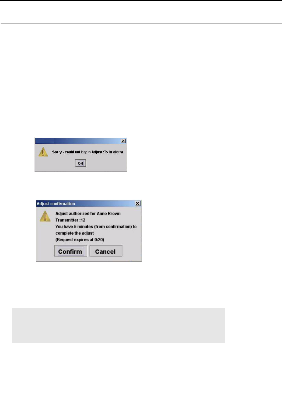
Series 7.0 Software (0510-1086-B) - User Guide 71
Adjust
4. Use the arrow buttons to find and select the patient or asset whose banding material needs
adjustment. Multiple patients or assets can be selected for adjusting.
a. Hold down the Ctrl key on the keyboard or, if the virtual keyboard is activated, click on the
Select Multiple button in the Adjust window. The Select Multiple button highlights when
activated.
b. Select the patients or assets whose banding material needs adjustment.
5. Click Start Adjust.
a. If the alarming band transmitter is in alarm, a dialog box appears indicating that the transmitter
is in alarm and the adjust function could not be performed. You must clear the alarm and re-try
the Adjust.
b. If successful, a dialog box appears showing the name of the patient or asset and the amount of
time allowed to adjust the banding material.
6. Click Confirm to confirm the Adjust.
7. Adjust the banding material and re-attach the transmitter.
The transmitter is active 60 seconds after both sides of the banding material are re-clamped. The
patient or asset being monitored by the transmitter is once again supervised by the system.
8. Click Cancel or X to cancel the Adjust request and close the window.
NOTE: If the banding material is not removed within the time allowed, a message
appears on the Client computer indicating that the adjust time expired. Do not continue
with the adjustment; a new adjust function must be initiated. Adjusting the banding
material after the adjustment time has expired will cause a Cut Band alarm.
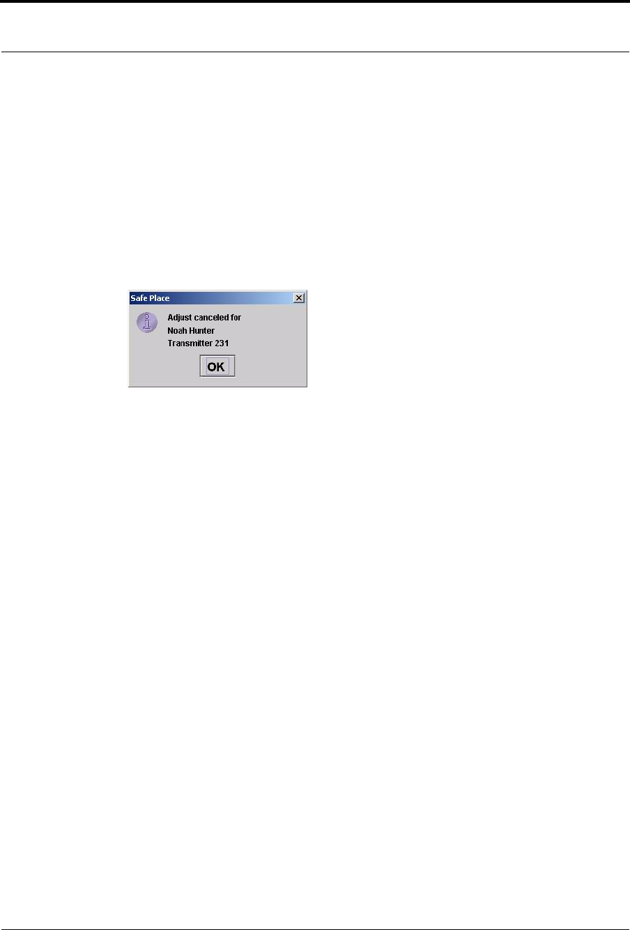
Chapter 3: Using the Software
72 Series 7.0 Software (0510-1086-B) - User Guide
To cancel an adjust
1. Select Login (or Functions if password protection is disabled).
2. Enter your Login and Password or use your identification card.
3. Click Adjust.
4. The Adjust Bands window appears.
5. Select the patient or asset currently being adjusted.
6. Click Cancel.
A dialog box appears to confirm that the adjust was canceled.
7. Click OK.
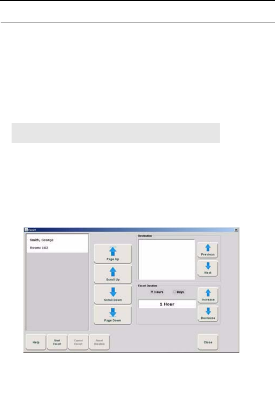
Series 7.0 Software (0510-1086-B) - User Guide 73
Escort
Escort
It may be necessary to temporarily move patients or assets within your facility from a protected area to an
unprotected area, or an area that is not monitored by the software, for example taking a patient to X-Ray. The
Escort function allows for movement of patients or assets by authorized staff within a facility while
maintaining a record of the patient or asset being escorted and the staff who authorized the action.
If an alarm from a Pendant, Fall Monitoring or Incontinence device is generated for the patient while he/she is
in Escort, the alarm cancels the Escort function. The alarm must then be cleared before the patient can be
placed back into Escort.
To perform an escort
1. Select Login (or Functions if password protection is disabled).
2. Enter your Login and Password or use your identification card.
3. Click Escort.
The Escort window appears. Patients or assets with alarming band transmitters, Wander
Management transmitters or Pendant, Fall Monitoring or Incontinence devices that currently exist
in the census are listed in the window.
FIGURE 3.11: Escort Window
NOTE: If a patient or asset is in alarm, the event must be cleared before the patient or
asset can be placed into Escort.
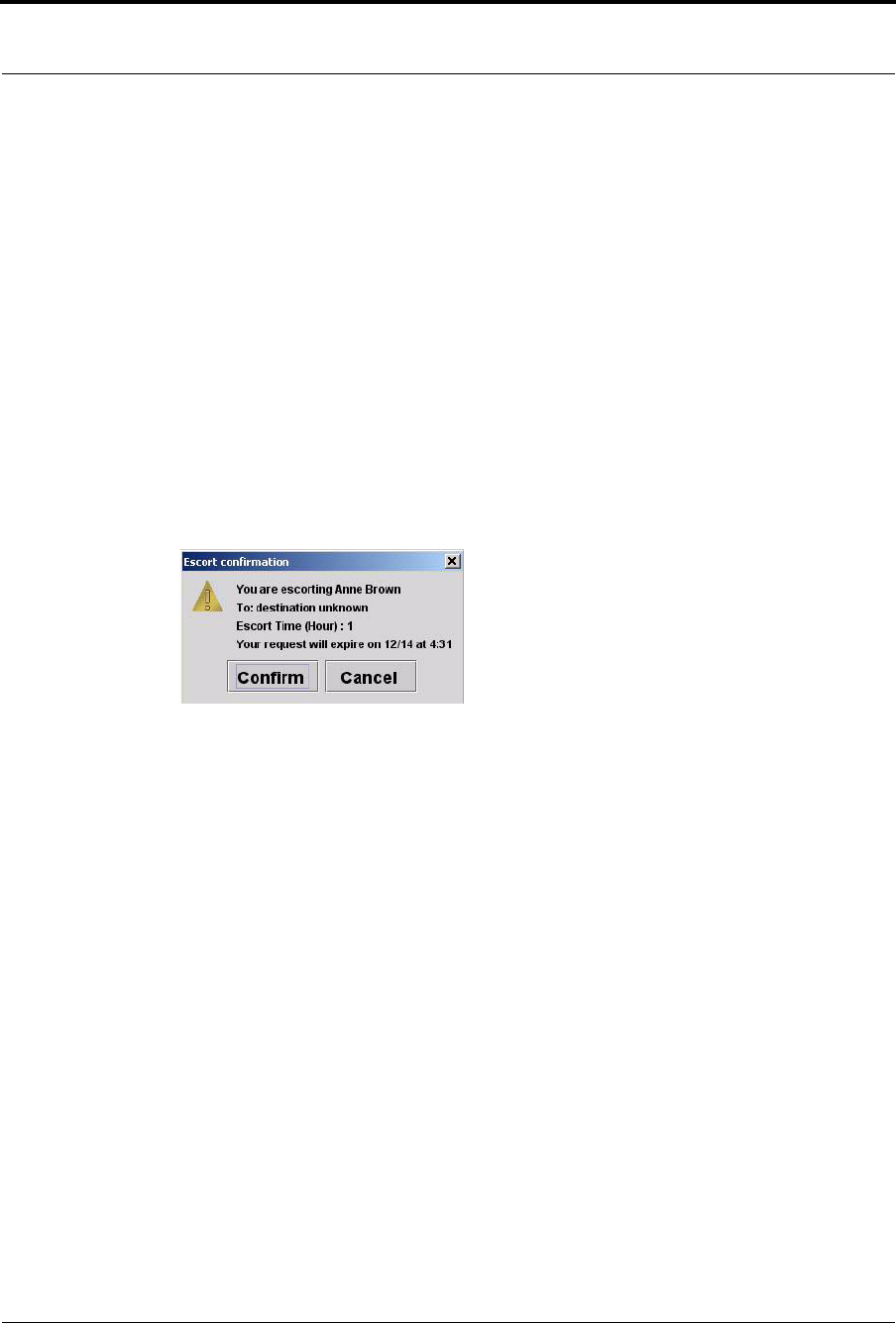
Chapter 3: Using the Software
74 Series 7.0 Software (0510-1086-B) - User Guide
4. Use the arrow buttons to find and select the patient or asset to be escorted. Multiple patients and
assets can be selected for escort providing that the Destination and Escort Duration is the same.
a. Hold down the Ctrl key on the keyboard or, if the virtual keyboard is activated, click on the
Select Multiple button in the Escort window. The Select Multiple button highlights when
activated.
b. Select the patients or assets to be escorted.
5. Use the arrow buttons to find and select the Destination, or the location to which the patient is to be
escorted.
6. Select the Escort Duration; the choices are Hours or Days. You can choose to set the Escort
Duration from 1 to 23 Hours or 1 to 23 Days.
7. Use the Increase and Decrease arrows to select the amount of time required to escort the patient.
8. Click Start Escort.
A dialog box appears showing the name of the patient or asset and the amount of time allowed for
the escort.
9. Click Confirm to confirm the Escort.
The patient or asset must be returned to the same unit within the selected time allowed, or an alarm
is issued. When initiating an Escort for a patient or asset using an alarming band transmitter, you
must wait 45 seconds before returning the patient or asset to the unit. Returning a patient or asset to
the unit before the 45 seconds time-lapse will result in an incomplete Escort.
10. Click Cancel or X to cancel the Escort request and close the window.
To reset escort duration time
1. Select Login (or Functions if password protection is disabled).
2. Enter your Login and Password or use your identification card.
3. Click Escort.
The Escort window appears (Figure 3.11 on page 73). Patients or assets with alarming band
transmitters, Wander Management transmitters or Pendant, Fall Monitoring or Incontinence
devices that currently exist in the census are listed in the window.
4. Use the arrow buttons to find and select the patient or asset whose escort duration time is to be reset.
Multiple patients or asset can be selected for resetting duration time, providing that the Destination
and reset duration time is the same.
5. Use the Hours or Days arrows to select the new time needed to escort the patient or asset.
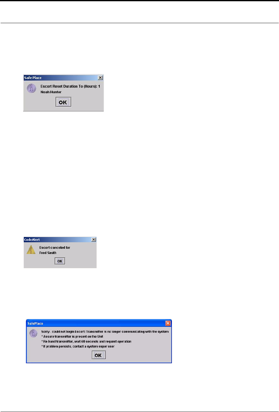
Series 7.0 Software (0510-1086-B) - User Guide 75
Escort
6. Click Reset Duration.
A dialog box appears showing the patient’s or asset’s name and the Escort Reset Duration hours or
days.
7. Click OK.
To cancel an escort
1. Select Login (or Functions if password protection is disabled).
2. Enter your Login and Password or use your identification card.
3. Click Escort.
The Escort window appears (Figure 3.11 on page 73). Patients or assets with alarming band
transmitters, Wander Management transmitters or Pendant, Fall Monitoring or Incontinence
devices that currently exist in the census are listed in the window.
4. Use the arrow buttons to find and select the patient or asset whose escort is to be canceled. Multiple
patients or assets can be selected for canceling.
5. Click Cancel.
A dialog box appears indicating that the escort for the selected patient or asset has been canceled.
6. Click OK.
Transmitter is no longer communicating with the system
The following dialog box appears when a transmitter is no longer communicating with the system and an
Escort attempt is made.
1. Follow the steps outlined in the dialog box.
2. Click OK.
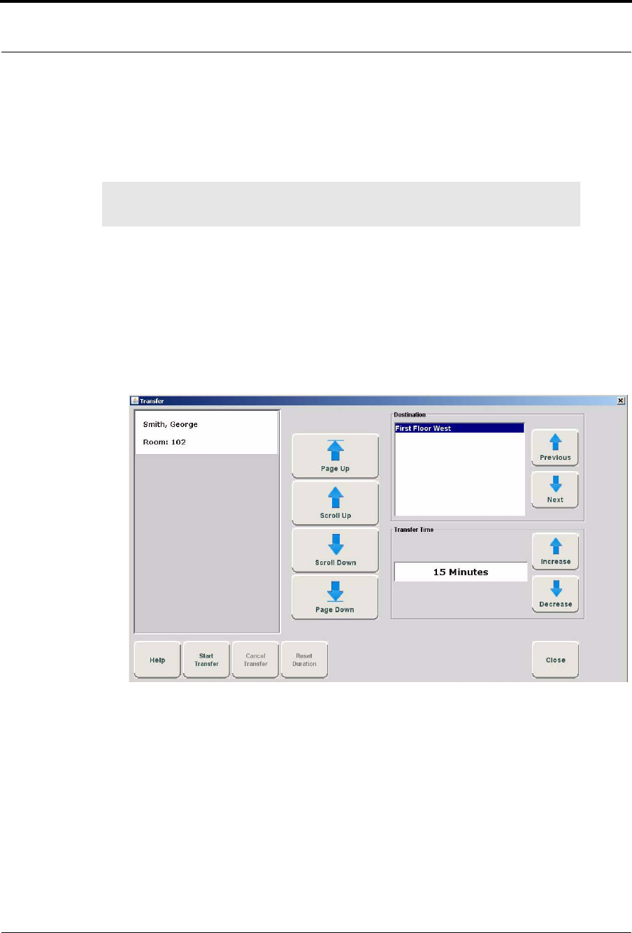
Chapter 3: Using the Software
76 Series 7.0 Software (0510-1086-B) - User Guide
Transfer
The Transfer function is used to move a patient or asset from one protected area to another protected area, for
example from Labor and Delivery to Post Partum. Use the following steps to transfer a patient.
To perform a transfer
1. Select Login (or Functions if password protection is disabled).
2. Enter your Login and Password or use your identification card.
3. Click Transfer.
The Transfer window appears. Patients or assets with alarming band transmitters, Wander
Management transmitters or Pendant, Fall Monitoring or Incontinence devices that currently exist
in the census are listed in the window.
FIGURE 3.12: Transfer Window
4. Use the arrow buttons to find and select the patient or asset to be transferred.
5. Use the arrow buttons to find and select the Destination, or the location to which the patient or
asset is to be transferred.
6. Use the Increase or Decrease arrows to select the amount of time required for the transfer.
7. Click Start Transfer.
NOTE: If a transmitter is in alarm, the event must be cleared before the patient or asset
can be placed into Transfer.
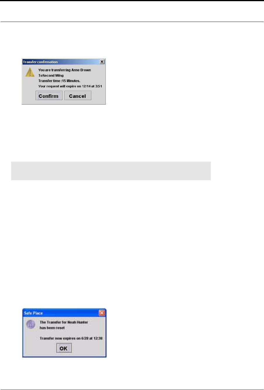
Series 7.0 Software (0510-1086-B) - User Guide 77
Transfer
8. A dialog box appears showing the patient’s or asset’s name, the amount of time allowed to transfer
the patient or asset, and the destination.
If the Transfer is for a Wander Management transmitter, Pendant, Fall Monitoring or Incontinence
device, the transfer occurs immediately.
9. Click Confirm to confirm the Transfer.
As soon as the patient's or asset’s transmitter passes through a protected zone that belongs to the
selected designation, the system recognizes that the transfer was successful and the Transfer
completes.
10. Click Cancel or X to cancel the Transfer request and close the window.
To reset a transfer duration time
1. Select Login (or Functions if password protection is disabled).
2. Enter your Login and Password or use your identification card.
3. Click Transfer.
The Transfer window appears (Figure 3.12 on page 76). Patients or assets that currently exist in
the census are listed in the window.
4. Use the arrow buttons to find and select the patient or asset whose transfer duration time is to be
reset.
5. Use the Increase or Decrease arrows to select the new time needed to transfer the patient or asset.
6. Click Reset Duration.
A dialog box appears showing the patient or asset name and the number of minutes that the transfer
is extended.
7. Click OK.
NOTE: When a transmitter successfully transfers to a unit with a different setting for
Band Slippage, a Begin Adjust alarm may be generated upon completion of the transfer.
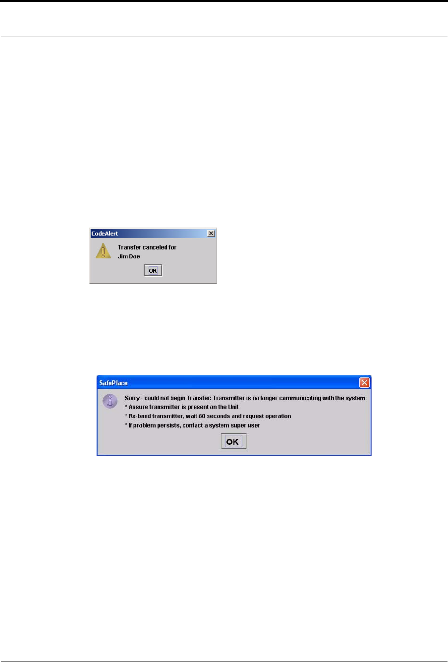
Chapter 3: Using the Software
78 Series 7.0 Software (0510-1086-B) - User Guide
To cancel a transfer
1. Select Login (or Functions if password protection is disabled).
2. Enter your Login and Password or use your identification card.
3. Click Transfer.
The Transfer window appears (see Figure 3.12 on page 76). Patients or assets with alarming band
transmitters, Wander Management transmitters or Pendant, Fall Monitoring or Incontinence
devices that currently exist in the census are listed in the window.
4. Select the patient or asset currently being transferred.
5. Click Cancel.
A dialog box appears to confirm that the transfer was canceled.
6. Click OK.
Transmitter is no longer communicating with the system
The following dialog box appears when a transmitter is no longer communicating with the system and a
Transfer attempt is made.
1. Follow the steps outline in the dialog box.
2. Click OK.
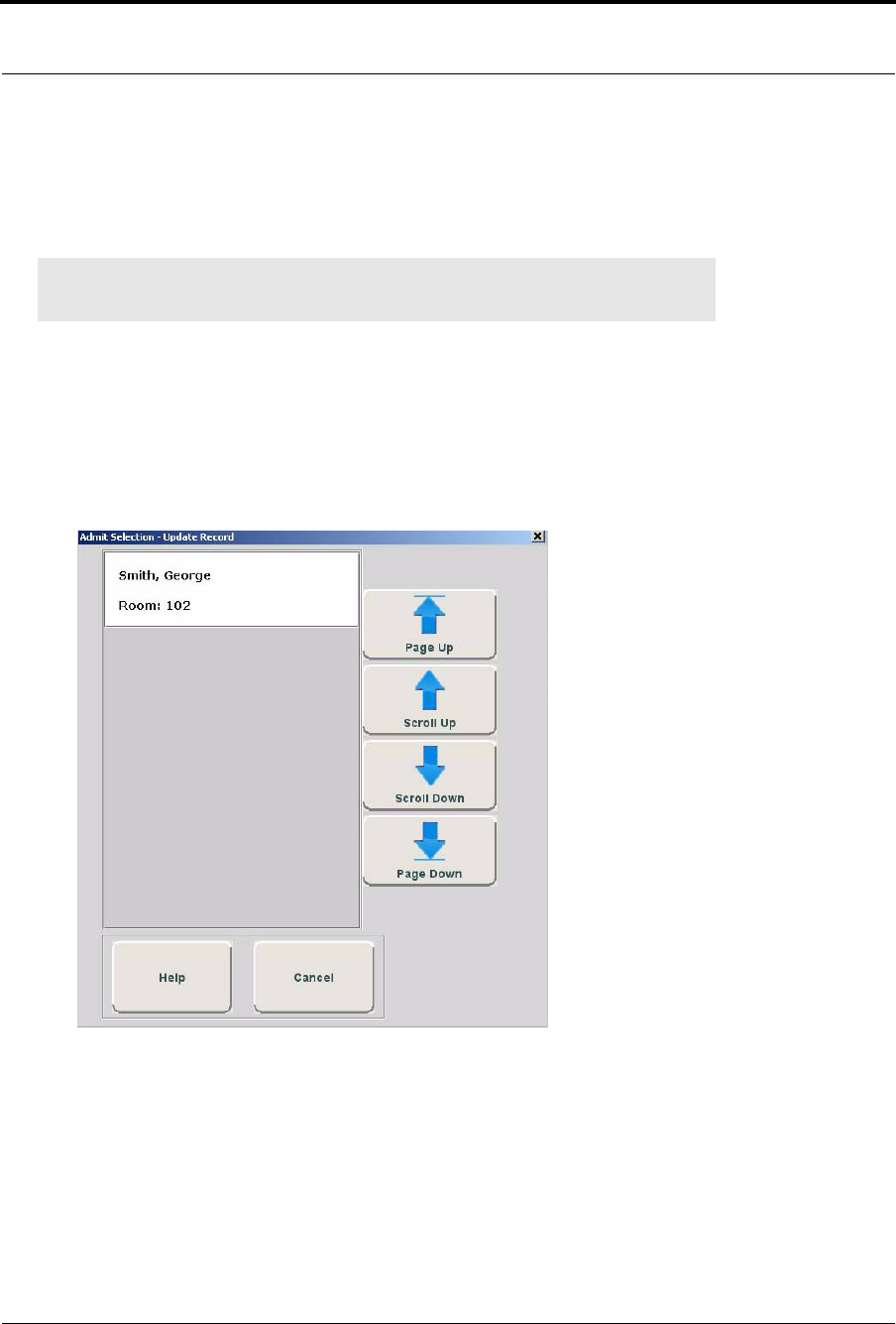
Series 7.0 Software (0510-1086-B) - User Guide 79
Update Record
Update Record
The Update Record function is used to update a patient or asset from one protected area to another protected
area, for example from Labor and Delivery to Post Partum. Use the following steps to transfer a patient.
To update a record
1. Select Login (or Functions if password protection is disabled).
2. Enter your Login and Password or use your identification card.
3. Click Update Record.
The Admit Selections - Update Records window appears. Patients or that currently exist in the
census are listed in the window.
FIGURE 3.13: Upgrade Record
4. Use the arrow buttons to find and select the patient to be updated.
5. Double click on the patient to bring up the Admit Information window and update admit
information; the yellow fields designate required entry.
6. Once information has been updated, click Save.
NOTE: If a transmitter is in alarm, the event must be cleared before the patient or asset
can be placed into Transfer.
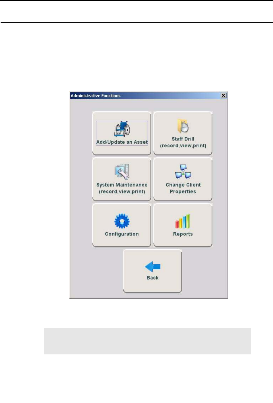
Chapter 3: Using the Software
80 Series 7.0 Software (0510-1086-B) - User Guide
Administrative Functions
Use Administrative Functions to Add/Update Assets, enter Staff Drill and System Maintenance information,
Change Client Properties, access the Configuration options and access available Reports.
FIGURE 3.14: Administrative Functions
The Back button closes the Administrative Function window and returns you to the Main Screen.
WARNING: When the software application is closed, indicators of alarms and events
will not be seen at the computer. Important! Only close the software application if
instructed to do so by authorized staff.
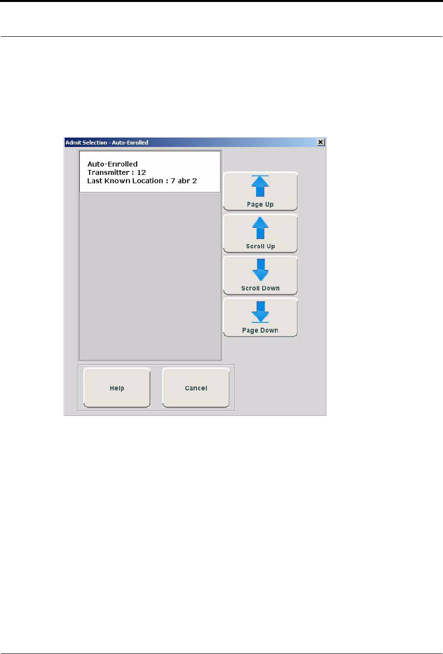
Series 7.0 Software (0510-1086-B) - User Guide 81
Administrative Functions
Add/Update An Asset
Transmitters that are automatically enrolled in the system can be assigned to an asset using this option. When
you click Add/Update An Asset, a window opens with only auto-enrolled transmitters.
FIGURE 3.15: Admit Selection
To Add/Update an asset
1. Select Login (or Functions if password protection is disabled).
2. Enter your Login and Password or use your identification card.
3. Click Administrative Functions.
4. Click Add/Update An Asset.
The Admit Selection window appears. Asset transmitters that currently exist in the census are
listed in the window.
5. Use the arrow buttons to find and select the transmitter number to be assigned.
6. Click on the Asset transmitter to bring up the Admit Information window and enter admit
information; the yellow fields designate required entry.
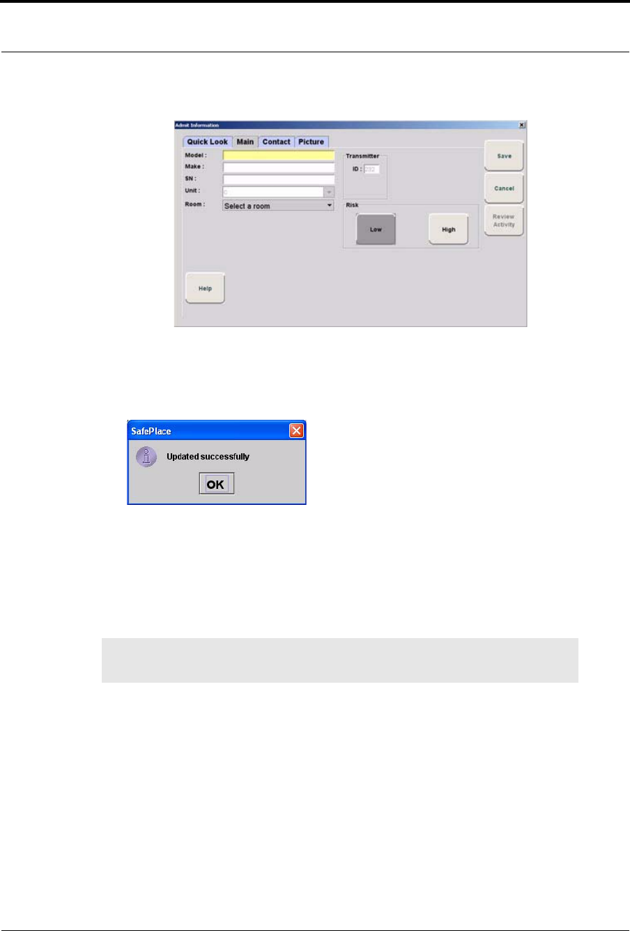
Chapter 3: Using the Software
82 Series 7.0 Software (0510-1086-B) - User Guide
FIGURE 3.16: Admit Information
7. Once admit information has been entered, click Save.
If the admit is successful, you will get the following dialog box:
8. Click OK.
Asset Main Information Tab
The Asset Main information tab allows you to enter identification information about the asset being admitted.
The yellow fields designate required entry.
1. Click Main on the toolbar.
2. In the Model field, type the model or description of the asset being admitted (required).
3. In the Make field, type the manufacturer’s information of the asset being admitted.
4. In the SN field, type the serial number of the asset being admitted.
5. In the Transmitter ID field, type the 3-digit ID number printed on the alarming band transmitter to
be assigned to the asset.
6. In the Unit field, select the unit to which the asset is currently assigned, even if the asset will not
remain in that unit (required).
7. Click the Risk level associated with the asset. Choices are Low or High. If your facility has
enabled the Lockdown on Cut Band Alarms feature, a Cut Band Alarm will trigger a Global
Lockdown when a High Risk level is selected for an asset transmitter.
NOTE: Information entered can only contain alphabetic and numeric characters, spaces,
and the following special characters: ! - _ , . ; [ ]{ }( )
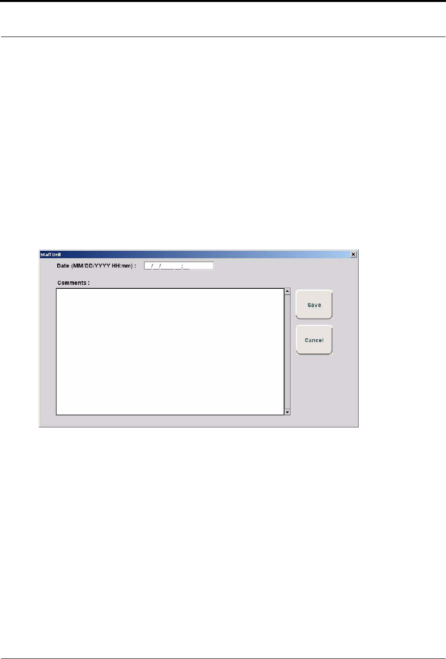
Series 7.0 Software (0510-1086-B) - User Guide 83
Administrative Functions
Staff Drill
When a staff drill is requested, the attendant performing the drill enters the information in the Staff Drill
window.
To access the Staff Drill window
1. Select Login (or Functions if password protection is disabled).
2. Enter your Login and Password or use your identification card.
3. Press Enter or click OK.
4. Select Administrative Functions.
5. Select Staff Drill.
The Staff Drill window opens.
FIGURE 3.17: Staff Drill
6. Enter the Date of the Staff Drill as the two digit month, followed by the two digit day, followed by
the four digit year. Enter the Time as the two digit hour followed by the two digit minute.
7. In the Comments field, enter your comments.
8. Do one of the following:
a. Click Save to save and return to the main window.
b. Click Cancel to return to the main window without saving.
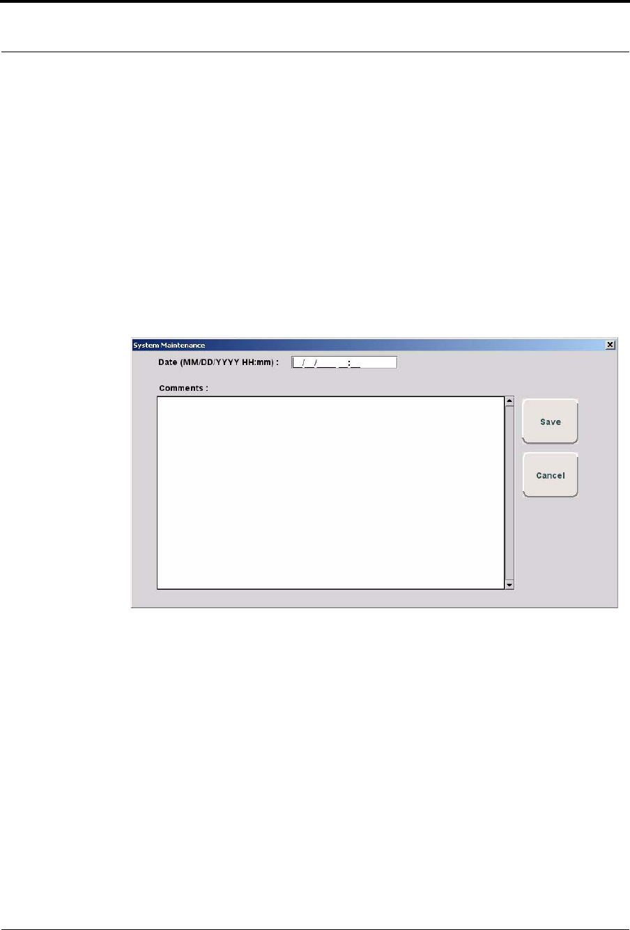
Chapter 3: Using the Software
84 Series 7.0 Software (0510-1086-B) - User Guide
System Maintenance
A log of maintenance performed on the system is logged in the System Maintenance window.
To access the System Maintenance window
1. Select Login (or Functions if password protection is disabled).
2. Enter your Login and Password or use your identification card.
3. Press Enter or click OK.
4. Select Administrative Functions.
5. Select System Maintenance.
The System Maintenance window opens.
FIGURE 3.18: System Maintenance
6. Enter the Date of the System Maintenance as the two digit month, followed by the two digit day,
followed by the four digit year. Enter the Time as the two digit hour followed by the two digit
minute.
7. In the Comments field, enter your comments.
8. Do one of the following:
a. Click Save to save and return to the main window.
b. Click Cancel to return to the main window without saving.
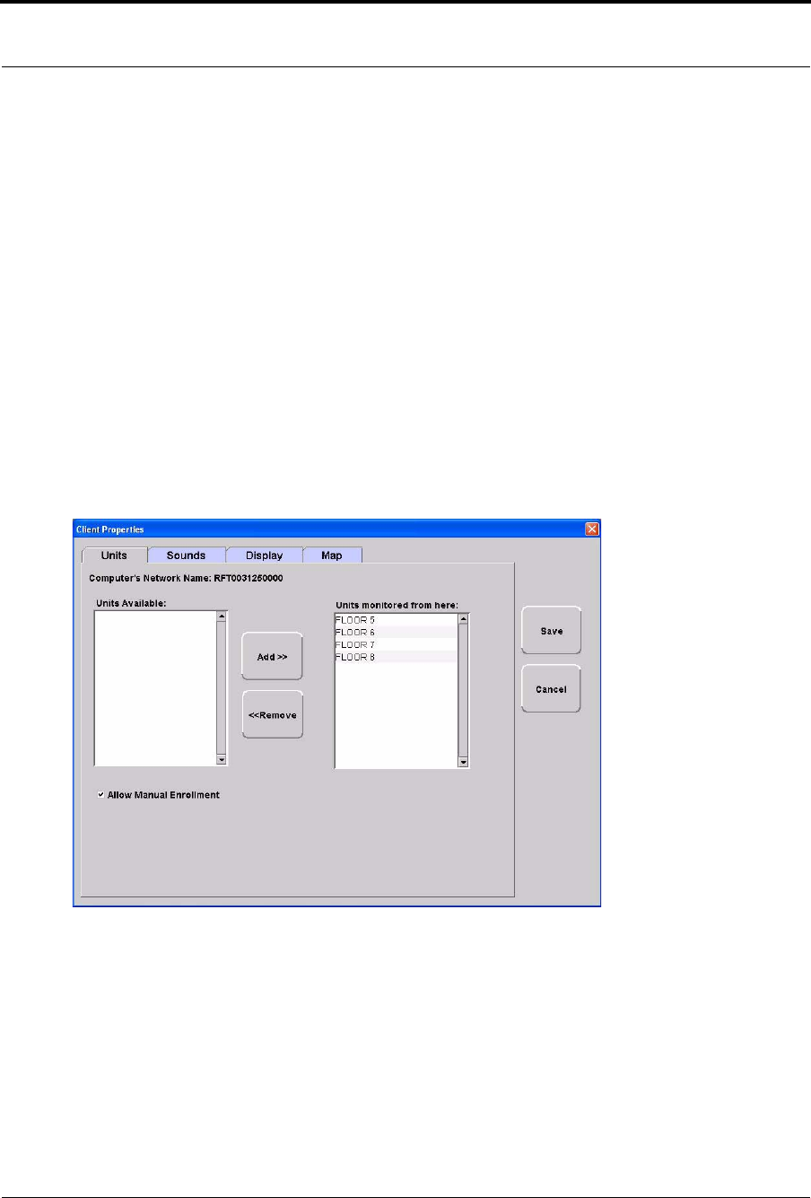
Series 7.0 Software (0510-1086-B) - User Guide 85
Administrative Functions
Changing Client Properties
When the software is running on the Central Server and each Client computer, and the System settings have
been defined, the next step in the installation process is to define the properties or settings of each Client
computer.
The changes you make in Client Properties affect only the Client computer you are configuring.
To access the Client Properties window
1. Select Login (or Functions if password protection is disabled).
2. Enter your Login and Password or use your identification card.
3. Press Enter or click OK.
4. Select Administrative Functions.
5. Select Change Client Properties.
The Client Properties window opens.
FIGURE 3.19: Client Properties
For more information about Client Properties, see the Series 7.0 Software Administrator Guide.
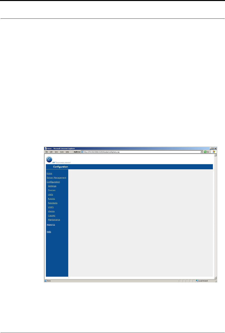
Chapter 3: Using the Software
86 Series 7.0 Software (0510-1086-B) - User Guide
Configuration
The Configuration options allow you to configure devices in the system. System configurations are done by
the System Administrator.
To access the Configuration home page
1. Select Login (or Functions if password protection is disabled).
2. Enter your Login and Password or use your identification card.
3. Press Enter or click OK.
4. Select Administrative Functions.
5. Select Configuration, or double-click the desk top icon.
The System Management home page opens.
6. Select Configuration.
The Configuration page opens with links to the Configuration menus.
FIGURE 3.20: Configuration Page
For more information about Configuration, see the Series 7.0 Software Administrator Guide.
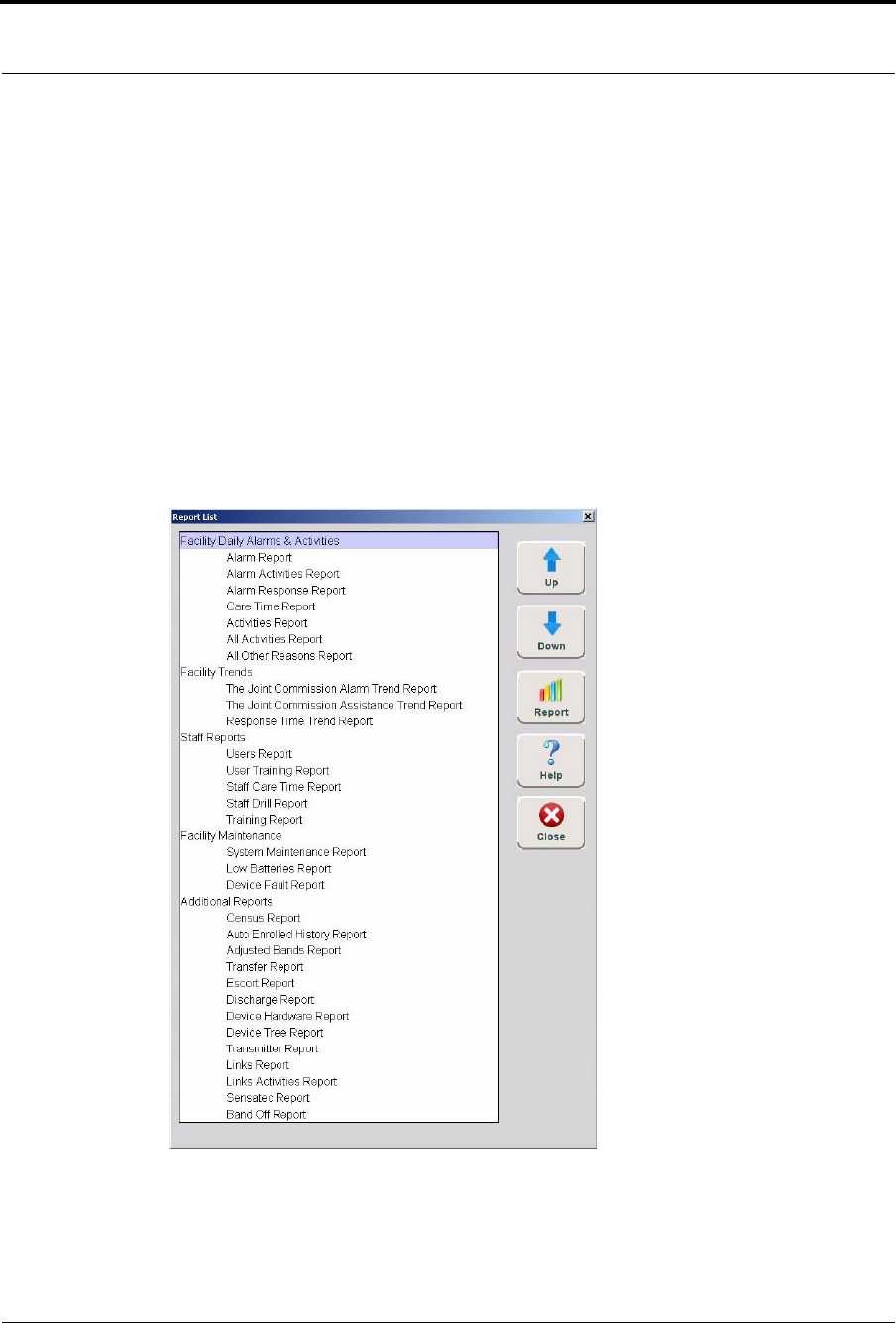
Series 7.0 Software (0510-1086-B) - User Guide 87
Administrative Functions
Reports
The Reports option accesses a list of all available reports. There are several System Reports that enable
you to view information about the activities of the system throughout the day, week, or month.
To access Reports
1. Select Login (or Functions if password protection is disabled).
2. Enter your Login and Password or use your identification card.
3. Press Enter or click OK.
4. Select Administrative Functions.
5. Select Reports.
The Reports window opens
FIGURE 3.21: Reports
Refer to Chapter 5, Using System Reports for detailed information about viewing, printing, saving and
filtering reports.
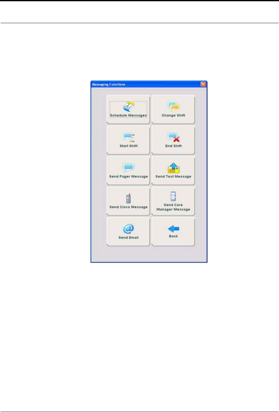
Chapter 3: Using the Software
88 Series 7.0 Software (0510-1086-B) - User Guide
Messaging Functions
The Messaging Functions allows you to schedule system messages, manage paging shifts and send messages
to staff via pager, text, Cisco phone, Care Manager and email.
FIGURE 3.22: Messaging Functions
Scheduled Messages
The Scheduled Messages feature allows you to schedule system messages to be sent to staff one time only or
on a daily, weekly or monthly basis.
To access the Scheduled Messages window
1. Select Login (or Functions if password protection is disabled).
2. Enter your Login and Password or use your identification card.
3. Press Enter or click OK.
4. Select Messaging Functions.
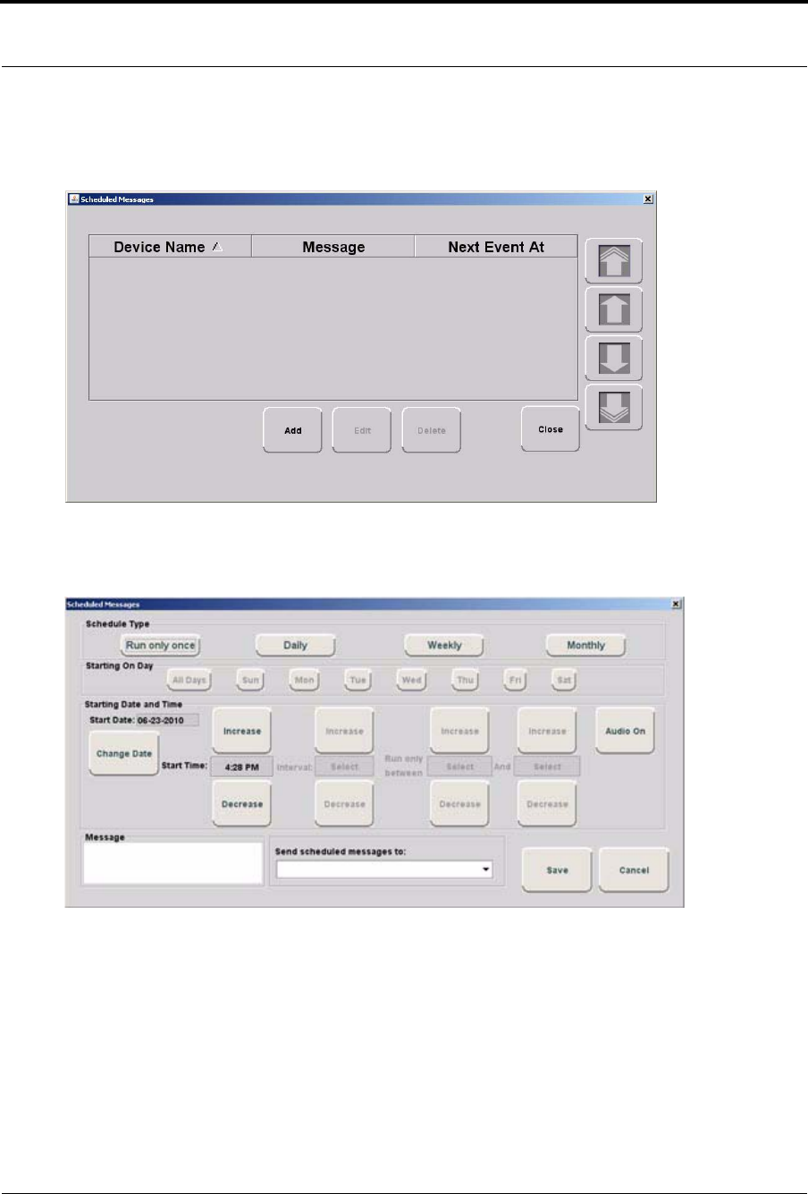
Series 7.0 Software (0510-1086-B) - User Guide 89
Messaging Functions
5. Select Scheduled Messages.
The Scheduled Messages window opens.
FIGURE 3.23: Scheduled Messages
6. Click Add to open the Scheduled Messages window.
FIGURE 3.24: Scheduled Messages window
7. Select the Schedule Type. Do you want the schedule message to:
•Run only once
•Daily
•Weekly
•Monthly
8. If you choose to run the scheduled message daily, you must select the day(s) you wish to run the
message. Choose the day(s) from the Starting On Day field.

Chapter 3: Using the Software
90 Series 7.0 Software (0510-1086-B) - User Guide
9. From the Starting Date and Time field, select a date and time to start the scheduled message. The
current date is displayed in the Start Date field. To change the date, click on Change Date and
choose a date from the popup calendar.
10. Choose a Start Time. The current time is displayed, click Increase or Decrease to select the
desired start time.
11. If you choose to run the scheduled message more than once daily, you must select a run Interval
and Run only between times. The Interval is how often you want the scheduled event to run.
Increments are 1 minute (0:01) to 11 hours and 59 minutes (11:59). Click Increase or Decrease to
select interval.
12. Click Increase or Decrease to select interval.
13. The Run only between range can be set for any minute of the day. Click Increase or Decrease to
select the starting Run only between time AND click Increase or Decrease to select the ending
Run only between time.
NOTES:
•The scheduled message Start Time must fall within the starting Run only between
time and the ending Run only between time range. For example, a scheduled
message with a start time of 8:00 A.M. must have a Run only between time window
that includes 8:00 A.M. A Run only between time of 7:00 A.M to 10:00 A.M. is
legitimate; it includes 8:00 A.M. A time of 4:00 A.M. to 7:00 A.M. is not a
legitimate Run only between time.
•The scheduled message’s Interval time must be less than the time window created
by the Run only between times. For example, a scheduled message with an interval
of 5 hours must have a Run only between time window of at least 6 hours.
14. The Audio button toggles On/Off. When Audio is turned On, the scheduled message will alarm at
the Client computer(s).
15. Enter the message you wish to send in the free text Message field.
16. From the Send scheduled messages to: pull down, select a message group or recipient to whom
the message will be sent.
17. Click Save or Cancel if you do not wish save your changes.
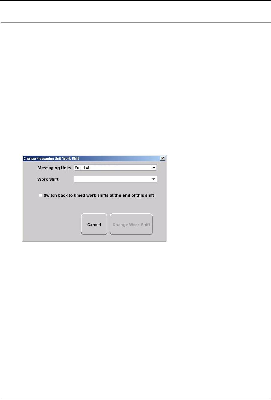
Series 7.0 Software (0510-1086-B) - User Guide 91
Messaging Functions
Changing Shift
In some cases, it may be necessary to change a message unit’s work shift. Use this feature to select a different
messaging unit and work shift. This feature can only be used if you currently use messaging with your
system.
To change a messaging unit work shift
1. Select Login (or Functions if password protection is disabled).
2. Enter your Login and Password or use your identification card.
3. Press Enter or click OK.
4. Select Messaging Functions.
5. Select Change Shift.
The Change Messaging Unit Work Shift window opens.
FIGURE 3.25: Change Message Unit Work Shift
6. From the Messaging Units drop-down, select the Message Unit you wish to change.
7. From the Work Shift drop-down, select a different work shift. The Change Work Shift button
enables.
8. If you wish to Switch back to timed work shift at the end of this shift, click the check box.
9. Click the Change Work Shift button.
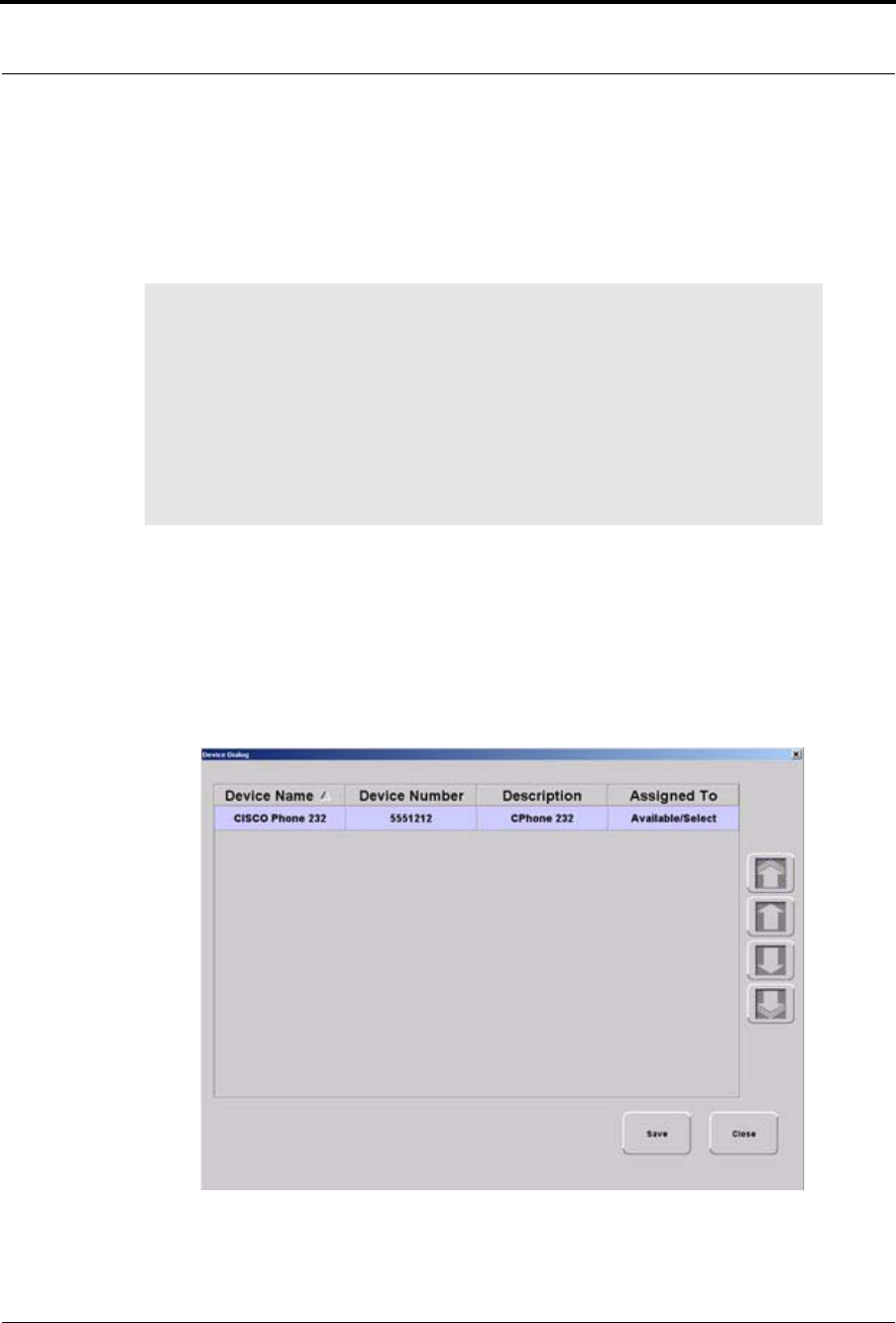
Chapter 3: Using the Software
92 Series 7.0 Software (0510-1086-B) - User Guide
Start Shift
At the start of the shift, use this feature to check out a Cisco phone. Cisco phones are configured by the
System Administrator and can only be used if you currently use Cisco phones with your system. For more
information, see the Series 7.0 Software Administrator Guide.
To check out a Cisco phone
1. Select Start Shift.
2. Use your proximity card or magnetic/barcode card or enter your Login and Password then press
Enter or click OK.
3. The Device Dialog window opens. Cisco phones currently available for checkout are listed in the
window.
FIGURE 3.26: Device Dialog
NOTE: The option to clear alarms at the point of care a feature of the Cisco phone. Below
are guide lines when clearing an alarm from the Cisco phone:
•If the “Clear” function is password protected, the user must be assigned that function in
order to clear an alarm from the Cisco phone. Additionally the phone or care manager
must be checked out to the user assigned.
•The Cisco phone chimes when a message is cleared. It is important to select the “When
the event occurs” field concurrently with the “When the event is cleared” field to
avoid getting chimes without getting the original alarm message.

Series 7.0 Software (0510-1086-B) - User Guide 93
Messaging Functions
4. Double click anywhere in the row containing the phone you wish to checkout. The user name
replaces Available/Select in the Assigned To column.
5. Click Save to close the window and checkout the phone. Only one phone can be checked out per
login. To check out another phone you must click Save and repeat the process.
6. Click Close to close the window without checking out the phone.
End Shift
At the end of the shift, use this feature to return the CISCO phone back into the system. To return a phone,
select End Shift. Use your proximity card or magnetic/barcode card or enter your Login and Password then
press OK. All phones checked out to the user are automatically returned to the Device Dialog list, no
confirmation of the return is given.
Send Message
In some cases, it may be necessary to send a manual message to a staff member.This feature can only be used
if your system is configured for messaging. There are five messaging methods.
•Send Pager Message
•Send Text Message (see note on page 94 regarding text message)
•Send Cisco Message (see notes on page 94 regarding Cisco phone message)
•Send Care Manager Message
•Send Email
Select the method that best suit your needs. The example below is for sending a manual Pager Message.
To send manual messages
1. Select Login (or Functions if password protection is disabled).
2. Enter your Login and Password or use your identification card.
3. Press Enter or click OK.
4. Select Messaging Functions.
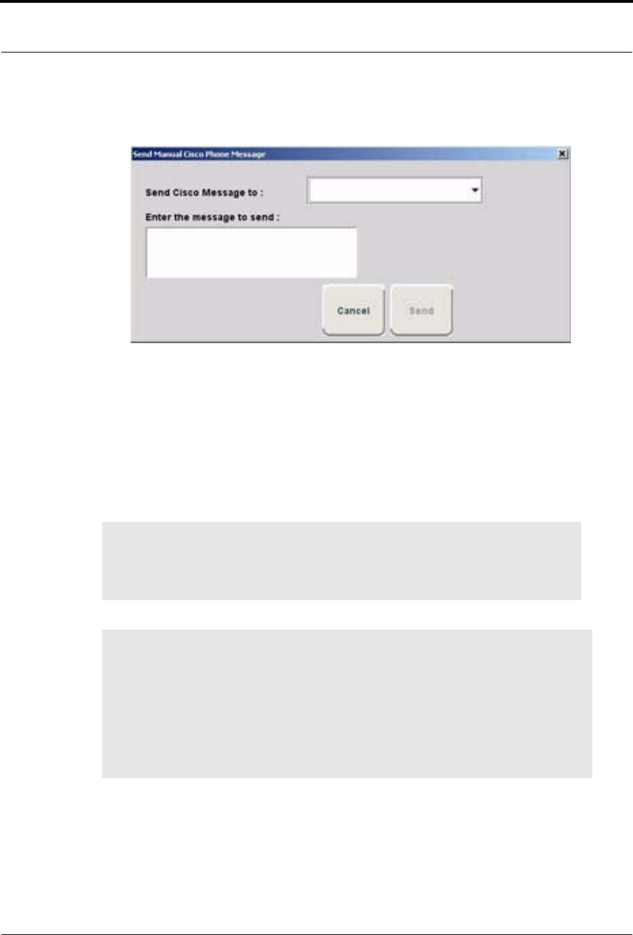
Chapter 3: Using the Software
94 Series 7.0 Software (0510-1086-B) - User Guide
5. Select Send Cisco Messages.
Send Manual Cisco Phone Message window opens.
FIGURE 3.27: Send Cisco Phone Message
6. From the Send Cisco Message to: drop-down, select the message group you wish to send a
manual page.
7. Type your message in the Enter the message to send: field.
8. Click Send to send your message.
9. Click Cancel if you do not wish to send the message.
10. Follow the same steps to send Pager, Text, Email, or Care Manager messages.
NOTE: The text messaging functionality is dependant on the performance constraints of
your network. This means that text messages may take a long time to get through or they
may appear in a different order then they were sent. Text message notifications should
not be used as the primary form of notification.
NOTES:
•The Cisco phone system will not issue a busy signal when the phone is in use. If there is
no answer on the other end, it may mean that the patient is on the phone.
•The following alarm events and information cannot be messaged to Cisco phones.
a. Asset Alarms
b. Scheduled Events
c. Any event that initially triggers a White Alarms (i.e. Auto-enroll, Discharge expired)
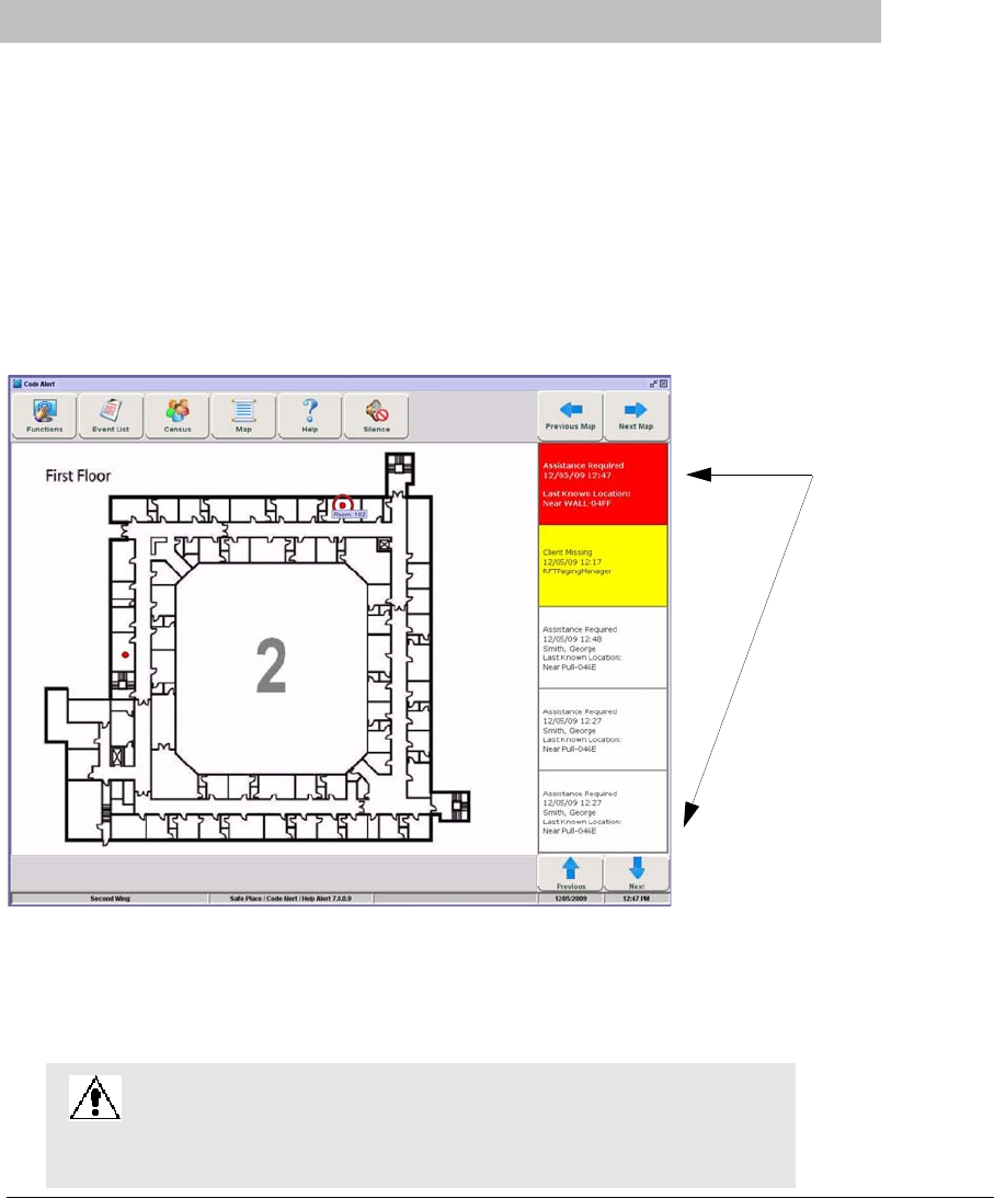
Series 7.0 Software (0510-1086-B) - User Guide 95
Chapter 4
Handling Events
Introduction
This chapter provides information about the Events. It provides a detail description of alarming events, the
devices that triggered the events and information about responding to the specific events.
Events
An event is an action that occurs in the software that requires a response from an authorized user. When an
event occurs, a message is displayed in the Event List indicating the relevant device, the patient’s or asset’s
name when applicable, and the type of event received.
FIGURE 4.1: Main Window
Click anywhere in the Alarm Message Box to access more information about the event and to select a cause
for the event, if applicable, from the Event Information window. These event causes are then logged into the
applicable reports. For information about reporting, see Chapter 5, Using System Reports.
WARNING: The Series 7.0 Software is designed and intended to work in
conjunction with a facility’s overall patient security program, including
reasonable operating policies and procedures. The Series 7.0 Software, by
itself, cannot prevent abductions or elopements.
Alarm Message Box
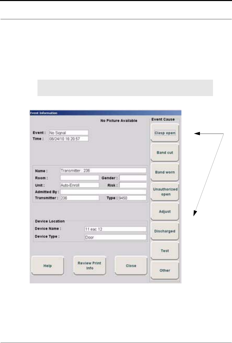
Chapter 4: Handling Events
96 Series 7.0 Software (0510-1086-B) - User Guide
Event Information Window
When an event occurs, an Alarm Message Box is displayed in the Event List. Click anywhere in the Alarm
Message Box to access the Event Information window. The Event Information window contains detailed
information about the event. If a picture is available, certain events will display the picture of the patient or
asset associated with the event.
Selecting an Event Cause will clear an alarm.
FIGURE 4.2: Event Information Window
NOTE: The Event Cause buttons in the Event Information window are different for each
event. See the following sections for detailed information.
Event Cause Buttons
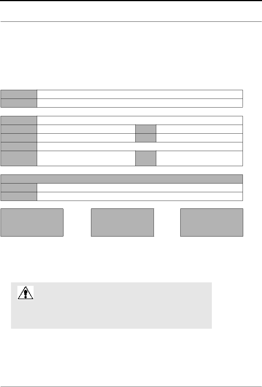
Series 7.0 Software (0510-1086-B) - User Guide 97
Event Types
Event Information Window Properties
The following table provides brief descriptions of the properties that appear in the Event Information
window.
Event Types
There are several different event types that can occur when using the Series 7.0 Software. The following
sections provide a brief overview of each event as well as an action to take if this event occurs.
Event Information Window
Event: the type of event recorded.
Time: the time that the event occurred.
Name: the transmitter ID number, or the name of the patient or asset to whom the transmitter is assigned.
Room: the room number of the patient or asset. Gender: the gender of the patient.
Unit: the unit that the patient or asset is assigned to. Risk: the risk level assigned to the patient or asset.
Admitted By: the staff member who performed the admission.
Transmitter: the identification number of the transmitter that
initiated the event. Type: the type of transmitter that sent the signal.
Device Location
Device Name: the name of the device that received the alarm.
Device Type: the type of device that received the alarm.
Help—displays help
information for the Event
Information window
Review Print Info—opens an
Event Information Report with
patient or asset, event and
deice location information
Close—closes the Event
Information window without
clearing the alarm.
WARNING: If you do not already have procedures in place, you
must establish procedures for your staff to follow to ensure patient
safety and to secure the area in the event of an alarm. Existing
procedures may require modification to incorporate optional
features. Failure to create or modify these procedures may result in
patient abduction or elopement.

Chapter 4: Handling Events
98 Series 7.0 Software (0510-1086-B) - User Guide
Red Alarms
The following sections provide detailed information about Red Alarms, responding to alarming events, and
the the way the event should be cleared. Red Alarms are high priority alarms. They are displayed in the
Alarm Message Box and the Event List sequentially as they occur. Red Alarms are displayed first in the
Alarm Message Box and Event list.
Door Alarm
When a patient wearing an alarming band transmitter is in an Exit Alarm Zone and the monitored door is
open, an alarm sounds at the Exit Alarm Controller, a message is displayed on the Client computer(s) in the
unit configured to monitor the transmitter, and the location of the Exit Alarm Zone is indicated by a flashing
icon on the map on the Client computer(s). Door Alarms are also displayed on remote notification devices.
To respond to a Door Alarm
1. Always follow your facility’s policies and procedure to ensure patient safety and secure the area.
2. Go to the alarming device and use your card reader access card (if applicable) or enter the
appropriate 4-digit security code to reset the alarm at the device. For more information about the
Security Code, contact your System Administrator.
3. If the Enforce Joint Commission reporting feature is activated, you must select an Event Cause
once the alarming device has been reset. When you reset the alarming device, the Red Alarm
changes to a White Alarm in the Alarm Message Box and Event List. If the Enforce Joint
Commission reporting feature is not activated, the Alarm Message Box clears once the alarm is
cleared at the device.
4. From the Client computer, click anywhere in the Door Alarm Message Box to access the Event
Information window.
5. Select one of the following causes for the Door Alarm:
•Escort problem—there was an issue while the patient was in escort.
•Transfer problem—there was an issue while the patient was in transfer.
•Accidentally too close to open door—the patient was near a door when it was opened.
•Noise —there were noise issues with the device.
•Test —the system was being tested.
•Other—opens a Clear Reason window, user must enter the cause in this window.
You cannot clear an event until you select the appropriate cause for the event. The event is cleared from
the Event List of every Client computer configured to monitor the unit.
NOTE: You can click Silence to stop the alarm sound at the Central Server or Client
computer. The alarm is silenced at that computer only, for the configured length of time;
however, the event still appears in the Event List. The next event automatically restarts
the alarm sound.

Series 7.0 Software (0510-1086-B) - User Guide 99
Event Types
Exit Alarm (Wide Gap)
A Wide Gap Exit Alarm occurs when a door or window monitored by a Door/Window transmitter is opened.
A Door/Window transmitter is a device that protects a door or window against unauthorized egress. When a
Wide Gap Exit Alarm occurs, a message is displayed on the Client computer(s) in the unit configured to
monitor the door or window, and the location of the Exit Alarm is indicated by a flashing icon on the map on
the Client computer(s).
To respond to a Wide Gap Exit Alarm
1. Always follow your facility’s policies and procedures to ensure patient safety and secure the area.
2. Locate the door or window that initiated the alarm.
3. Close the door or window. The system records the event and clears the alarm when the door or
window is closed.
Smoke Alarm
When a smoke detector that is integrated with the system is activated, an alarm sounds, a message is
displayed on the Client computer(s) in the unit configured to monitor the device, and the location of the
Smoke Alarm is indicated by a flashing icon on the map on the Client computer(s). An event is reported in
the Event List each time the smoke detector is activated.
To respond to a Smoke Alarm
1. Always follow your facility’s policies and procedures to ensure patient safety and secure the area.
2. Locate the alarming device. Smoke Alarms must be reset at the alarming device.The system
records the event as a Reset when the smoke detector is reset.
NOTE: No local audible alarms are sounded from the Door/Window transmitter when an
alarm occurs.
NOTE: You can click Silence to stop the alarm sound at the Central Server or Client
computer. The alarm is silenced at that computer only, for the configured length of time;
however, the event still appears in the Event List. The next event automatically restarts
the alarm sound.

Chapter 4: Handling Events
100 Series 7.0 Software (0510-1086-B) - User Guide
Perimeter Alarm
A Perimeter Alarm occurs when the doors monitored by the system are in Perimeter mode and a door is
opened. Perimeter mode is when a door is in a lockdown state as a result of system configuration or an event.
Perimeter mode also occurs when a door is open at the time a Cut Band Alarm occurs.
When a Perimeter alarm occurs, an alarm sounds at the Exit Alarm Controller, a message is displayed on the
Central Server or Client computer(s) in the unit configured to monitor the door, and the location of the Exit
Alarm is indicated by a flashing icon on the map on the Client computer(s).
To respond to a Perimeter Alarm
1. Always follow your facility’s policies and procedures to ensure patient safety and secure the area.
2. Locate the alarming device. Perimeter Alarms must be reset at the alarming device.
3. Go to the Exit Alarm Controller and use your card reader access card (if applicable) or enter the
appropriate 4-digit security code. For more information about the Security Code, contact your
System Administrator. The system records the event as a Reset when the appropriate code is
entered.
4. If the Enforce Joint Commission reporting feature is activated, you must select an Event Cause
once the alarming device has been reset. When you reset the alarming device, the Red Alarm
changes to a White Alarm in the Alarm Message Box and Event List. If the Enforce Joint
Commission reporting feature is not activated, the Alarm Message Box clears once the alarm is
cleared at the device.
5. From the Central Server or Client computer, click anywhere in the Perimeter Alarm Message Box
to access the Event Information window.
6. Select one of the following causes for the Perimeter Alarm:
•Escort problem—there was an issue while the patient was in escort.
•Transfer problem—there was an issue while the patient was in transfer.
•Accidentally close to open door—the patient was near a door when it was opened.
•Noise —there were noise issues with the device.
•Test —the system was being tested.
•Other—opens a Clear Reason window, user must enter the cause in this window.
You cannot clear an event until you select the appropriate cause for the event. The event is cleared from
the Event List of every Client computer configured to monitor the unit.
NOTE: You cannot silence or reset the Exit Alarm Controller’s alarms from the Central
Server and Client computer(s). You must reset the alarm at the Exit Alarm Controller.
NOTE: Any perimeter alarms that occur due to a door open during a Cut Band Alarm
require that the Cut Band Alarm be cleared at the computer first, before the doors are
reset or cleared.
NOTE: You can click Silence to stop the alarm sound at the Central Server or Client
computer. The alarm is silenced at that computer only, for the configured length of time;
however, the event still appears in the Event List. The next event automatically restarts
the alarm sound.

Series 7.0 Software (0510-1086-B) - User Guide 101
Event Types
Cut Band Alarm
When the banding material on a patient’s alarming band transmitter is cut, tampered with or opened without
authorization (which includes opening the transmitter when a timed event has expired), an alarm is sounded
on the computer configured to monitor the unit, a message is displayed in the Event List, and the location of
the Alarming Band Receiver that detected the event is indicated on the map on the computer(s). Cut Band
Alarms are also displayed on remote notification devices.
If your facility has enabled the Lockdown on Cut Band Alarms feature, a Cut Band Alarm will trigger a
Global Lockdown.You can configure the Global Lockdown feature to lock doors at All exits or By
transmitter units. However if a Cut Band Alarm is initiated during an Escort or a Transfer, the system
automatically locks All exits since the transmitter in Escort or Transfer may be outside of its protected unit
and displays the alarm on all Client computers and Quick Look displays.
To respond to a Cut Band Alarm
1. Always follow your facility’s policies and procedures to ensure patient safety and secure the area.
2. Verify the transmitter is applied correctly and without signs of damage or tampering.
3. From the Client computer, click anywhere in the Cut Band Alarm Message Box to access the
Event Information window.
4. Select one of the following event causes:
•Clasp open —one of the clasps on the transmitter was open.
•Band cut—the banding material on the transmitter was cut.
•Band worn—the banding material on the transmitter is worn and must be replaced.
•Unauthorized open-—an unauthorized person opened the transmitter clasp.
•Adjust—a transmitter was being adjusted without authorization, an adjust was not requested
or an adjust occurred after the adjust time expired.
•Discharged —the transmitter was being removed in a discharge without authorization, a
discharge was not requested or a discharge occurred after the adjust time allowed.
•Test —the system was being tested.
•Other—opens a Clear Reason window, user must enter the cause in this window.
You cannot clear an event until you select the appropriate cause for the event. The event is cleared from
the Event List of every Client computer configured to monitor the unit.
NOTE: Any perimeter alarms that occur due to a door open during a Cut Band Alarm
require that the Cut Band Alarm be cleared at the computer first, before the doors are
reset or cleared.
NOTE: You can click Silence to stop the alarm sound at the Central Server or Client
computer. The alarm is silenced at that computer only, for the configured length of time;
however, the event still appears in the Event List. The next event automatically restarts
the alarm sound.

Chapter 4: Handling Events
102 Series 7.0 Software (0510-1086-B) - User Guide
Band Off Alarm
When the Smart Sense Banding Material on a Smart Sense Infant Transmitter is removed, tampered with or
comes off of the infant’s extremity due to newborn weight loss, an alarm is sounded on the computer
configured to monitor the unit, a message is displayed in the Event List, and the location of the Alarming
Band Receiver that detected the event is indicated on the map on the computer(s). Band Off Alarms are also
displayed on remote notification devices. There are three measurements of tamper detection for a Band Off
Alarm.
•Temperature—detects the change in temperature of the transmitter
•Resistance—detects the stretching of the banding material
•Capacitance—detects the change in contact between transmitter and infant
If your facility has enabled the Lockdown on Band Off Alarms feature, a Band Off Alarm will trigger a
Global Lockdown.You can configure the Global Lockdown feature to lock doors at All exits or By
transmitter units. However if a Band Off Alarm is initiated during an Escort or a Transfer, the system
automatically locks All exits since the transmitter in Escort or Transfer may be outside of its protected unit
and displays the alarm on all Client computers and Quick Look displays.
To respond to a Band Off Alarm
1. Always follow your facility’s policies and procedures to ensure patient safety and secure the area.
2. Verify the transmitter is applied correctly and without signs of damage or tampering.
3. From the Client computer, click anywhere in the Band Off Alarm Message Box to access the Event
Information window.
4. Select one of the following event causes:
• Band Off—the banding material is off the infant.
•Clasp open —one of the clasps on the transmitter was open.
•Band cut—the banding material on the transmitter was cut.
•Band worn—the banding material on the transmitter is worn and must be replaced.
•Unauthorized open-—an unauthorized person opened the transmitter clasp.
•Adjust—a transmitter was being adjusted without authorization, an adjust was not requested
or an adjust occurred after the adjust time expired.
•Discharged —the transmitter was being removed in a discharge without authorization, a
discharge was not requested or a discharge occurred after the adjust time allowed.
•Test —the system was being tested.
•Other—opens a Clear Reason window, user must enter the cause in this window.
You cannot clear an event until you select the appropriate cause for the event. The event is cleared from
the Event List of every Client computer configured to monitor the unit
NOTE: Any perimeter alarms that occur due to a door open during a Band Off Alarm
require that the Band Off Alarm be cleared at the computer first, before the doors are
reset or cleared.

Series 7.0 Software (0510-1086-B) - User Guide 103
Event Types
Mismatch Alarm
A Mismatch alarm occurs if an Infant transmitter is located within proximity of a Mother transmitter that is
linked to a different infant transmitter.
To respond to a Mismatch Alarm
1. Always follow your facility’s policies and procedures to ensure patient safety and secure the area.
2. Click anywhere in the message box to access the Event Properties window.
3. Select one of the following Event reasons:
•No problem—no issue was found.
•Wrong Infant—the Infant transmitter is brought to the wrong Mother transmitter.
•Mothers bonding—while two mothers were socializing, one of the Mother transmitters
picked up the other Mother’s Infant transmitter signal.
•Infant not present—an Infant transmitter was not present.
•Test —the system was being tested.
•Other—opens a Clear Reason window, user must enter the cause in this window.
You cannot clear an event until you select the appropriate cause for the event. The event is cleared from
the Event List of every Client computer configured to monitor the unit.
Match Alarm
You can configure the system to require a Mother/Infant match before an infant can be discharged. The
Match Alarm occurs when an infant is discharged and the alarming band material is cut, before performing
the required Mother/Infant match. The Require Mother/Infant match before discharge is configured in the
Configuration, Global Settings menu (refer to the Series 7.0 Software Administrator Guide).
To respond to a Match Alarm
1. Always follow your facility’s policies and procedures to ensure patient safety and secure the area.
2. Click anywhere in the Match Alarm Message Box to access the Event Information window.
3. Click Clear. If necessary, perform the discharge function again by first performing the Mother/
Infant match.
NOTE: You can click Silence to stop the alarm sound at the Central Server or Client
computer. The alarm is silenced at that computer only, for the configured length of time;
however, the event still appears in the Event List. The next event automatically restarts
the alarm sound.
NOTE: You can click Silence to stop the alarm sound at the Central Server or Client
computer. The alarm is silenced at that computer only, for the configured length of time;
however, the event still appears in the Event List. The next event automatically restarts
the alarm sound.

Chapter 4: Handling Events
104 Series 7.0 Software (0510-1086-B) - User Guide
Link Alarm
This alarm occurs when there is a problem linking the Infant transmitter to a Mother transmitter. For
example, the Infant transmitter may already be linked to another Mother transmitter.
To respond to a Link Alarm
1. Always follow your facility’s policies and procedures to ensure patient safety and secure the area.
2. Click anywhere in the Link Alarm Message Box to access the Event Information window.
3. Click Clear.
4. If necessary, verify the identity of the mother and infant then relink the Mother and Infant
transmitters.
Check Alarm
No message has been received from the patient’s transmitter or the device in the patient’s room during the
Inactivity Check-In period. The Check message will remain until the patient’s transmitter checks in, an
Alarm message is received, or the event is manually cleared at the Client computer(s).
To respond to a Check Alarm
1. Always follow your facility’s policies and procedures to ensure patient safety and secure the area.
2. Locate the device.
3. Verify that no patient emergency exists.
4. From the Client computer, click anywhere in the Inactivity Check-In Alarm Message Box to access
the Event Information window.
5. Select Clear to clear the Inactivity Check-In alarm.
NOTE: You can click Silence to stop the alarm sound at the Central Server or Client
computer. The alarm is silenced at that computer only, for the configured length of time;
however, the event still appears in the Event List. The next event automatically restarts
the alarm sound.

Series 7.0 Software (0510-1086-B) - User Guide 105
Event Types
No Signal Alarm
A No Signal alarm occurs when the system is unable to locate the transmitter within the required supervision
time.
To respond to a No Signal Alarm
1. Always follow your facility’s policies and procedures to ensure patient safety and secure the area.
2. Verify transmitter is fastened correctly and without signs of damage.
For more information, refer to the Patient Transmitter User Guide (PN 0510-1013) or the Infant
Transmitter User Guide (PN 0510-1006).
3. From the Client computer, click anywhere in the No Signal Alarm Message Box to access the
Event Information window.
4. Select one of the following event causes:
•Clasp open —one of the clasps on the transmitter was open.
•Band cut—the banding material on the transmitter was cut.
•Band worn—the banding material on the transmitter is worn and must be replaced.
•Unauthorized open-—an unauthorized person opened the transmitter clasp.
•Adjust—a transmitter was being adjusted without authorization.
• Discharged —the transmitter was being removed in a discharge without authorization.
•Test —the system was being tested.
•Other—opens a Clear Reason window, user must enter the cause in this window.
You cannot clear an event until you select the appropriate cause for the event. The event is cleared
from the Event List of every Client computer configured to monitor the unit.
5. Multiple No Signal alarms may be an indication that Receiver coverage may be inadequate.
Contact your System Administrator.
WARNING: You must test all transmitters prior to use, and periodically
thereafter, to verify proper operation. Failure to test the transmitters
before use can result in system failure and/or an elopement or abduction.
In addition, failure to test transmitters voids the RF Technologies Product
Warranty.
NOTE: You can click Silence to stop the alarm sound at the Central Server or Client
computer. The alarm is silenced at that computer only, for the configured length of time;
however, the event still appears in the Event List. The next event automatically restarts
the alarm sound.

Chapter 4: Handling Events
106 Series 7.0 Software (0510-1086-B) - User Guide
Assistance Required Alarm
An Assistance Required alarm occurs when a QR or 9600 Series device belonging to a patient alarms. The
Alarm message will remain until the alarming device is reset. An Assistance Required alarm is also activated
in response to a Fall Management System alert.
To respond to an Assistance Required Alarm
1. Always follow your facility’s policies and procedures to ensure patient safety and secure the area.
2. Locate the alarming device. Assistance Required Alarms must be reset at the alarming device.
3. Reset the alarming device. The system records the event as a Reset when the alarming device is
reset.
4. If responding to a Fall Management System alert, the system will automatically reset and begin
monitoring once the patient is placed back on the Sensor Pad (refer to the “Advanced 3-Way Care
Solution” on page 30 or the “Advanced 4-Way Care Solution” on page 32).
5. If the Enforce Joint Commission reporting feature is activated, you must select an Event Cause
once the alarming device has been reset. When you reset the alarming device, the Red Alarm
changes to a White Alarm in the Alarm Message Box and Event List. If the Enforce Joint
Commission reporting feature is not activated, the Alarm Message Box clears once the alarm is
cleared at the device.
6. From the Client computer, click anywhere in the Assistance Required Alarm Message Box to
access the Event Information window.
7. Select one of the following event causes:
•Fall —the patient had fallen and needed assistance.
•Water—the patient required water.
•Food—the patient required food.
•Talk-—the patient had matters to discuss with the attendant.
•Bathroom—the patient required bathroom assistance.
•Test —the system was being tested.
•Other—opens a Clear Reason window, user must enter the cause in this window.
You cannot clear an event until you select the appropriate cause for the event. The event is cleared
from the Event List of every Client computer configured to monitor the unit.
NOTE: You can click Silence to stop the alarm sound at the Central Server or Client
computer. The alarm is silenced at that computer only, for the configured length of time;
however, the event still appears in the Event List. The next event automatically restarts
the alarm sound.

Series 7.0 Software (0510-1086-B) - User Guide 107
Event Types
Fall Alarm
This alarm occurs when a patient removes his/her weight from the sensor pad. The alarm clears when weight
is re-applied to the pad. The Alarm Message Box will remain on the Client computer until the alarming
device is reset.
To respond to an Fall Alarm
1. Always follow your facility’s policies and procedures to ensure patient safety and secure the area.
2. Secure the patient from a potential fall situation.
3. The system will automatically reset and begin monitoring once the patient is placed back on the
Sensor Pad.
4. If the Enforce Joint Commission reporting feature is activated, you must select an Event Cause
once the alarming device has been reset. When you reset the alarming device, the Red Alarm
changes to a White Alarm in the Alarm Message Box and Event List. If the Enforce Joint
Commission reporting feature is not activated, the Alarm Message Box clears once the alarm is
cleared at the device.
5. From the Client computer, click anywhere in the Fall Alarm Message Box to access the Event
Information window.
6. Select one of the following event causes:
•Confused —the patient attempted to get up without assistance.
•Bathroom—the patient required bathroom assistance.
•Water—the patient required water.
•Food—the patient required food.
•Talk-—the patient had matters to discuss with the attendant.
•Test —the system was being tested.
•Other—opens a Clear Reason window, user must enter the cause in this window.
You cannot clear an event until you select the appropriate cause for the event. The event is cleared from the
Event List of every Client computer configured to monitor the unit.
NOTE: You can click Silence to stop the alarm sound at the Central Server or Client
computer. The alarm is silenced at that computer only, for the configured length of time;
however, the event still appears in the Event List. The next event automatically restarts
the alarm sound.

Chapter 4: Handling Events
108 Series 7.0 Software (0510-1086-B) - User Guide
Wet Alarm
This alarm occurs when fluids are detected on an incontinence pad.
To respond to a Wet Alarm
1. Always follow your facility’s policies and procedures to ensure patient safety and secure the area.
2. Proceed to the patient and verify incontinence occurrence. Detach the incontinence pad; the alarm
clears when the incontinence pad is detached.
3. If the Enforce Joint Commission reporting feature is activated, you must select an Event Cause
once the alarming device has been reset. When you reset the alarming device, the Red Alarm
changes to a White Alarm in the Alarm Message Box and Event List. If the Enforce Joint
Commission reporting feature is not activated, the Alarm Message Box clears once the alarm is
cleared at the device.
4. From the Client computer, click anywhere in the Wet Alarm Message Box to access the Event
Information window.
5. Select one of the following event causes:
•Urine —the patient has urinated on him/herself.
•Sweat—the patient’s sweat has caused the bed to be wet.
•Stool—the patient has defecated on him/herself.
•Spill—the patient has spilled liquid on the bed.
•Other—opens a Clear Reason window, user must enter the cause in this window.
You cannot clear an event until you select the appropriate cause for the event. The event is cleared from the
Event List of every Client computer configured to monitor the unit.
Turn Alarm
This alarm occurs when the time on the Control Unit expires.
To respond to a Turn Alarm
1. Always follow your facility’s policies and procedures to ensure patient safety and secure the area.
2. Proceed to the patient and re-position the patient (refer to the applicable Control Unit’s in-service
manual).
NOTE: You can click Silence to stop the alarm sound at the Central Server or Client
computer. The alarm is silenced at that computer only, for the configured length of time;
however, the event still appears in the Event List. The next event automatically restarts
the alarm sound.

Series 7.0 Software (0510-1086-B) - User Guide 109
Event Types
3. If the Enforce Joint Commission reporting feature is activated, you must select an Event Cause
once the alarming device has been reset. When you reset the alarming device, the Red Alarm
changes to a White Alarm in the Alarm Message Box and Event List. If the Enforce Joint
Commission reporting feature is not activated, the Alarm Message Box clears once the alarm is
cleared at the device.
4. From the Client computer, click anywhere in the Turn Alarm Message Box to access the Event
Information window.
5. Select one of the following event causes:
•Left —the patient needs to be turned to his/her left side.
•Right—the patient needs to be turned to his/her right side.
•Supine—the patient needs to be turned to the Supine position, on his/her back.
•Fowler—the patient needs to be turned to the Fowler position, semi-upright sitting 45-60
degrees.
•Semi-Fowlers —the patient needs to be turned to the Semi-Fowler’s position (semi-upright
sitting 30-45 degrees).
You cannot clear an event until you select the appropriate cause for the event. The event is cleared from the
Event List of every Client computer configured to monitor the unit
Server Missing Alarm
This alarm occurs when the Client computer has lost communications with the Central Server.
To respond to a Server Missing Alarm
1. Verify with the System Administrator that the Series 7.0 Software is running on the Client
computer(s).
2. From the Client computer, click anywhere in the Server Missing Alarm Message Box to access the
Event Information window.
The Event Information window only provides time of the Server Missing event. This information
may be helpful when communicating the event to your System Administrator.
3. Click Close.
4. Contact your System Administrator or call RF Technologies Technical Support Team at (800) 669-
9946 or (262) 790-1771.
NOTE: A Server Missing alarm will automatically clear when communications with the
Server is restored. It cannot be cleared by the user.

Chapter 4: Handling Events
110 Series 7.0 Software (0510-1086-B) - User Guide
Yellow Alarms
The following sections provide detailed information about Yellow Alarms, responding to alarming events,
and the way the event should be cleared. Yellow Alarms are medium priority alarms. They are displayed in
the Event List sequentially as they occur. Yellow Alarms are displayed below Red Alarms.
No Signal Alarm (9600 Series Pendant)
A No Signal alarm for the 9600 Series Pendant occurs when the system is unable to locate the pendant within
the required supervision time. It is important to note if the person to whom the pendant is assigned has taken
the pendant out of the area (i.e. weekend pass, doctor’s appointment). If the pendant is not out of the area,
locate the pendant and verify proper operation.
Multiple No Signal alarms may also be an indication that Router coverage is inadequate. If problem persist,
contact your System Administrator or call RF Technologies Technical Support Team at (800) 669-9946 or
(262) 790-1771.
To respond to a No Signal Alarm
1. Always follow your facility’s policies/procedures to ensure patient safety.
2. From the Client computer, click anywhere in the No Signal Alarm Message Box to access the
Event Information window.
3. Click Clear to clear the alarm. If you attempt to clear the alarm before it has been on the screen for
more than 30 seconds, it will keep re-posting and then auto clear at the end of the 30 seconds.
NOTE: No Signal alarms will repeat at each supervision check-in time as long as the
system is unable to locate the pendant. If the transmitter is lost, stolen or does not exist,
remove the pendant from the person to whom it is assigned.
NOTE: You can click Silence to stop the alarm sound at the Central Server or Client
computer. The alarm is silenced at that computer only, for the configured length of time;
however, the event still appears in the Event List. The next event automatically restarts
the alarm sound.

Series 7.0 Software (0510-1086-B) - User Guide 111
Event Types
Client Missing
This alarm occurs when the Client computer is not communicating with the system network.
To respond to a Client Missing Alarm
1. Verify with the System Administrator that the Series 7.0 Software is running on the Client
computer(s).
2. Check the power and network cable connecting the missing Client computer.
3. From the Client computer, click anywhere in the Client Missing Alarm Message Box to access the
Event Information window.
The Event Information window provides more information about the Client Missing event. This
information may be helpful when communicating the event to your System Administrator.
4. Click Close.
5. Contact your System Administrator or call RF Technologies Technical Support Team at (800) 669-
9946 or (262) 790-1771.
Device Fault
This alarm occurs when a problem has been detected with a device. There are several types of Device Fault
events that can occur in the system, for example: Device Tamper, RF Interference, Communications Failure,
RFT Paging Manager.
Other possible causes for Device Fault alarms are that the device has experienced a loss of power, it has an
invalid address, or the network connection is broken. Quick Response devices also report low battery
conditions. Additionally, if a Serial Receiver has been enrolled in the system, a Device Fault alarm will occur
until a QR transmitter is enrolled.
NOTE: A Client Missing alarm may not necessarily involve a Client computer. The
Client Missing alarm could be generated by a service utilized by the system, for example
the SNMP Agent, DB Service or Paging Manager.
NOTE: A Device Tamper alarm is generated when the Nurse Call cord set is removed
from the CA520 control unit while a patient is being monitored. To avoid this type of
alarm, disconnect the Nurse Call cord set while the control unit is in the Silence mode.
NOTE: When a RFT Paging Manager Device Fault occurs, pages will not be sent or
received. Additionally, any new alarms will be ignored by the paging system until the
Device Fault is resolved.

Chapter 4: Handling Events
112 Series 7.0 Software (0510-1086-B) - User Guide
To respond to a Device Fault Alarm
1. From the Client computer, click anywhere in the Alarm Message Box to access the Event
Information window.
2. The Event Information window provides more information about the Device Fault event. This
information may be helpful when communicating the event to your System Administrator.
3. Contact your System Administrator or call RF Technologies Technical Support Team at (800) 669-
9946 or (262) 790-1771.
Low Battery
This alarm appears in bottom toolbar when a transmitter currently enrolled in the system has a low battery.
You cannot clear a Low Battery Alarm; the alarm remains for the duration of time that the transmitter is
enrolled in the system. It does not disappear until the transmitter is discharged from the system and removed
from the facility or assigned a Missing status in the Configurations, Global Settings menu (refer to the Series
7.0 Software Administrator Guide).
Once the transmitter is discharged from the system, follow your warranty policy regarding the discard of the
transmitter. For more information about transmitters and transmitter care, see the appropriate Transmitter
User Guide.
NOTES:
•The system will not allow you to link a Mother transmitter that has a low battery.
•Quick Response devices page low battery conditions as Device Faults.
•A Low Battery Alarm is cleared for a QR or 9600 Series device when the battery is
replaced.
•When the battery on the CA420 or CA520 is low, the red light flashes every 10
seconds, the buzzer chirps and the nurse call triggers momentarily. When CA420 or
CA520 is used with a Universal transmitter a low battery will also triggers an
Assistance Required alarm at the computer every few seconds. Replace the low
battery immediately to avoid this anomaly.

Series 7.0 Software (0510-1086-B) - User Guide 113
Event Types
Tamper Alarm
The Universal Transceiver’s tamper functionality operated in several modes depending on the device and the
type of tamper interference. In either case, when initiated, a Ta mp er alarm event will be listed on the Event
List at the Central Server. The types of tamper events are:
•Case Open Tamper— initiated when the case to the Universal transceiver is opened.
•Mounting Tape Tamper—initiated when the PCB is separated from the enclosure
•Nurse Call Cord Set Tamper—initiated when the Nurse Call Cord set is removed from
the Nurse Call transceiver.
•Externals Enclosure Tamper —initiated when the external closure of the PIR Sensor is opened.
Below is a table showing the type of tamper event associated with a particular device.
Nurse
Call EAC Door/
Window Door Manual
Reset Door
Check-in PIR Smoke CO
Case Open Tamper xx x x x x
Mounting Tape Tamper xx x x x
Nurse Call Cord Set Tamper x
External Enclosure Tamper x

Chapter 4: Handling Events
114 Series 7.0 Software (0510-1086-B) - User Guide
White Alarms
The following sections provide detailed information about White Alarms, responding to alarming events, and
the way the events should be cleared. White Alarms are low priority alarms. They are displayed in the Alarm
Message Box and the Event List sequentially as they occur. White Alarms are displayed below Yellow
Alarms.
Auto-Enroll
The Auto-Enroll feature automatically enrolls alarming band transmitters into the system without requiring a
manual admit. Once the transmitter is auto-enrolled, the system monitors the transmitter for Door, Cut Band,
or No Signal alarms.
To respond to an Auto-Enroll
1. From the Client computer (s), click anywhere in the Auto-Enroll Alarm Message Box to access the
Event Information window.
2. Select one of the followings:
•Clear—clears the Auto-Enroll from the Alarm Message Box and the Event List.
•Admit—opens the Admit Information window for that transmitter so that you can assign the
transmitter to a patient.
•Close—closes the Admit Information window without clearing the Auto-Enroll.
To permanently silence an Auto-Enroll
1. From the Client computer(s), click anywhere in the Auto-Enroll
Alarm Message Box to access the Event Information window.
2. Click the Silence button. When an alarm is permanently
silenced, a silence icon appears in the Alarm Message box for
that alarm.
Admit Completed
This alarm occurs when the Admit function for a patient is completed. This dialog box only appears if the
software has been configured to confirm the Admit.The Confirm Admit is configured in the Configuration,
Global Settings menu (refer to the Series 7.0 Software Administrator Guide).

Series 7.0 Software (0510-1086-B) - User Guide 115
Event Types
Pre-Enroll Expired
This alarm occurs when the amount of time allowed for a Pre-Enroll transmitter to be banded has expired and
the Pre-Enroll has not completed properly.
To respond to a Discharge Expired Alarm
1. If the transmitter has not yet been banded, click anywhere in the Pre-Enroll Expired Alarm
Message Box to access the Event Information window.
2. Select Clear.
3. Perform the Pre-Enroll function again.
Discharge Expired
This alarm occurs when the amount of time allowed for an alarming band transmitter to be removed has
expired and the discharge has not been completed properly.
To respond to a Discharge Expired Alarm
1. If the transmitter has not yet been removed, click anywhere in the Discharge Expired Alarm
Message Box to access the Event Information window.
2. Select one of the following event causes:
•Patient Delayed—the patient is delayed and requires more time for the discharge.
•Attendant Delayed—the attendant was delayed in discharging the patient.
•Test—the system was being tested.
•Other—opens a Clear Reason window, user must enter the cause in this window.
You cannot clear an event until you select the appropriate cause for the event. If the patient is not
being discharged, the patient’s information is still in the database and the software continues to
assist staff in monitoring the patient.
3. Perform the Discharge function again.
Discharge Completed
This alarm occurs when the Discharge for a patient is completed. This dialog box only appears if the software
has been configured to confirm the discharge.The Confirm Discharge is configured in the Configuration,
Global Settings menu (refer to the Series 7.0 Software Administrator Guide).

Chapter 4: Handling Events
116 Series 7.0 Software (0510-1086-B) - User Guide
Escort to Expire
This alarm occurs when the time allowed for a patient to be escorted will expire in the configured time. The
alarming band transmitter, in the Escort mode, has not been moved from or has not yet been returned to the
protected area.
To respond to an Escort to Expire
1. Determine the location of the patient.
2. If the patient is secure and will not be returned to the protected area soon, clear the Escort to Expire
alarm and reset the duration time for the Escort.
3. If the patient has not yet been moved, clear the Escort to Expire alarm and cancel the escort.
Escort Expired
This alarm occurs when the selected amount of time required for a patient to be escorted has expired and the
transmitter, in the Escort mode, has not been moved from or has not yet been returned to the protected area.
To respond to an Escort Expired Alarm
1. Determine the location of the patient.
2. From the Client computer, click anywhere in the Escort Expired Alarm Message Box to access the
Event Information window.
3. Select one of the following event causes:
•Patient Delayed—the patient was delayed and the Escort may need more time.
•Failed to start—the Escort was never started.
•Escort Completed—the patient was successfully escorted.
•Test—the system was being tested.
•Other—opens a Clear Reason window, user must enter the cause in this window.
You cannot clear an event until you select the appropriate cause for the event.
4. If the patient has not yet been moved, perform the Escort function again.
5. If the patient has been escorted and is being returned to the monitored area:
a. Bring the patient back through the door; a Door Alarm will occur.
b. Follow the procedures for handling a Door Alarm (refer to “Door Alarm” on page 98).
c. Select Escort problem for the cause of the Door Alarm.
Escort Completed
This alarm occurs when the Escort for a patient is completed. This dialog box only appears if the software has
been configured to confirm the escort. The Confirm Escort is configured in the Configuration, Global
Settings menu (refer to the Series 7.0 Software Administrator Guide).

Series 7.0 Software (0510-1086-B) - User Guide 117
Event Types
Transfer to Expire
This alarm occurs when the time allowed for a patient to be transferred will expire in the configured time (if
the allotted time was configured for greater than 15-minutes) and the alarming band transmitter, in the
Transfer mode, has not been moved from one protected area to another.
To respond to a Transfer to Expire
1. Determine the location of the patient.
2. If the patient is secure and will not be transferred to a protected area soon, clear the Transfer to
Expire alarm and reset the duration time for the Transfer.
3. If the patient has not yet been moved, clear the Transfer to Expire alarm and cancel the Transfer.
Transfer Expired
This alarm occurs when the selected amount of time required for a patient to be transferred has expired and
the alarming band transmitter, in the Transfer mode, has not reached its destination.
To respond to a Transfer Expired Alarm
1. Determine the location of the patient.
2. From the Client computer, click anywhere in the Transfer Expired Alarm Message Box to access
the Event Information window.
3. Select one of the following event causes:
•Patient Delayed—the patient was delayed and needs more time for the transfer.
•Failed to Start—the Transfer was never started; or the patient was never transferred.
•Transfer Completed—the patient was successfully transferred to the destination.
•Test—the system was being tested.
•Other—opens a Clear Reason window, user must enter the cause in this window.
You cannot clear an event until you select the appropriate cause for the event.
4. If the patient has not yet been transferred, perform the Transfer function again.
5. If the patient has left the initial unit but has not arrived at the transfer unit:
a. Bring the patient through the door of the unit to which they are being transferred; a Door
Alarm may occur.
b. Follow the procedures for handling a Door Alarm (refer to “Door Alarm” on page 98).
c. Select Transfer problem for the cause of the Door Alarm.
d. If No Signal alarms occur, contact an Administrative user to manually transfer the transmitter
to the new unit.
Transfer Completed
This alarm occurs when a Transfer for a patient is completed. This dialog box only appears if the software has
been configured to confirm the transfer.The Confirm Transfer is configured in the Configuration, Global
Settings menu (refer to the Series 7.0 Software Administrator Guide).

Chapter 4: Handling Events
118 Series 7.0 Software (0510-1086-B) - User Guide
Begin Adjust
This alarm occurs after a configured amount of time to remind staff to check the alarming band transmitter
for band slippage. The time for the Require band slippage check is configured in the Configuration, Units
menu (refer to the Series 7.0 Software Administrator Guide).
To respond to an Adjust Alarm
1. Determine that the patient is secure.
2. Click anywhere in the Begin Adjust Alarm Message Box to access the Event Information window.
3. Click Clear.
4. If necessary, perform the Adjust function.
Adjust Expired
This alarm occurs when the selected amount of time required for the adjustment of the banding material has
expired and the adjustment has not been completed properly.
To respond to an Adjust Expired Alarm
1. Determine that the patient is secure.
2. If the banding material has not yet been adjusted, click anywhere in the Adjust Expired Alarm
Message Box to access the Event Information window.
3. Click Clear.
4. Perform the Adjust function again.
Adjust Competed
This alarm occurs when the Adjust function for a patient is completed. This dialog box only appears if the
software has been configured to confirm the Adjust.The Confirm Adjust is configured in the Configuration,
Global Settings menu (refer to the Series 7.0 Software Administrator Guide).
Scheduled Event
This alarm occurs when the scheduled time for an event (activity) is at hand. The event can be scheduled as a
one time only event or it can be scheduled to run daily, weekly or monthly.
To respond to a Scheduled Event
1. Proceed to the Client computer to view the reason for the scheduled event.
2. Click anywhere in the Scheduled Event Alarm Message Box to access the Event Information
window.
3. Click Clear.
4. If necessary, perform the Scheduled Event.

Series 7.0 Software (0510-1086-B) - User Guide 119
Event Types
Blue Alarms
The following sections provide detailed information about Blue Alarms, responding to alarming events, and
the way the events should be cleared. Blue Alarms are high priority asset alarms. They are displayed in the
Event List sequentially as they occur. Blue Alarms are displayed below White Alarms.
Door Alarm
When an asset banded with an alarming band transmitter is in an Exit Alarm Zone and the monitored door is
open an alarm sounds at the Exit Alarm Controller, a message is displayed on the Client computer(s) in the
unit configured to monitor the transmitter, and the location of the Exit Alarm Zone is indicated by a flashing
icon on the map on the Client computer(s).
To respond to a Blue Door Alarm
1. Go to the alarming device and use your card reader access card (if applicable) or enter the
appropriate 4-digit security code to clear the alarm at the device. For more information about the
Security Code, contact your System Administrator.
2. If the Enforce Joint Commission reporting feature is activated, you must select an Event Cause
once the alarming device has been reset. When you reset the alarming device, the Blue Alarm
changes to a Light Blue Alarm in the Alarm Message Box. If the Enforce Joint Commission
reporting feature is not activated, the Alarm Message Box clears once the alarm is cleared at the
device.
3. From the Client computer, click anywhere in the Door Alarm Message Box to access the Event
Information window.
4. Select one of the following causes for the Door Alarm:
•Clear—no reason specified.
•Test —the system was being tested.
•Other—opens a Clear Reason window, user must enter the cause in this window.
You cannot clear an event until you select the appropriate cause for the event. The event is cleared from
the Event List of every Client computer configured to monitor the unit.
NOTE: You can click Silence to stop the alarm sound at the Central Server or Client
computer. The alarm is silenced at that computer only, for the configured length of time;
however, the event still appears in the Event List. The next event automatically restarts
the alarm sound.

Chapter 4: Handling Events
120 Series 7.0 Software (0510-1086-B) - User Guide
Cut Band Alarm
When an asset transmitter is tampered with (cut band, improperly removed), an alarm is sounded on every
Client computer configured to monitor the unit, a message is displayed in the Event List, and the location of
the Alarming Band Receiver that detected the event is indicated on the map on the Client computer(s).
If your facility has enabled the Lockdown on Cut Band Alarms feature and the transmitter is configured as a
“High Risk” asset transmitter, a Cut Band Alarm will trigger a Global Lockdown. You can configure the
Global Lockdown feature to lock doors at All exits or By transmitter units. However, if a Cut Band Alarm is
initiated during an Escort or a Transfer, the systems automatically locks All exits and displays the alarm on all
Client computers and Quick Look displays.
To respond to a Blue Cut Band Alarm
1. Verify transmitter is applied correctly and without signs of damage or tampering.
2. From the Client computer, click anywhere in the Cut Band Alarm Message Box to access the
Event Information window.
3. Select one of the following event causes:
•Clear—no reason specified.
•Test —the system was being tested.
•Other—opens a Clear Reason window, user must enter the cause in this window.
You cannot clear an event until you select the appropriate cause for the event. The event is cleared from
the Event List of every Client computer configured to monitor the unit.
NOTE: When an asset transmitter is configured as HIGH priority, a Cut Band Alarm will
trigger a Global Lockdown. An asset transmitter configured as LOW priority will not
trigger a Global Lockdown during a Cut Band.
NOTE: Any perimeter alarms that occur due to a door open during a Cut Band Alarm
require that the Cut Band Alarm be cleared at the computer first, before the doors are
reset or cleared.
NOTE: You can click Silence to stop the alarm sound at the Central Server or Client
computer. The alarm is silenced at that computer only, for the configured length of time;
however, the event still appears in the Event List. The next event automatically restarts
the alarm sound.

Series 7.0 Software (0510-1086-B) - User Guide 121
Event Types
No Signal Alarm
The specified asset transmitter has not sent a signal to the system within the required time.
To respond to a Blue No Signal Alarm
1. Verify transmitter is fastened correctly and without signs of damage or tampering.
2. From the Client computer, click anywhere in the No Signal Alarm Message Box to access the
Event Information window.
3. Select one of the following event causes:
•Test —the system was being tested.
•Other—opens a Clear Reason window, user must enter the cause in this window.
You cannot clear an event until you select the appropriate cause for the event. The event is cleared
from the Event List of every Client computer configured to monitor the unit.
4. A No Signal alarm may be an indication that Receiver coverage may be inadequate. Contact your
System Administrator.
Light Blue Alarms
The following sections provide detailed information about Light Blue Alarms, responding to alarming
events, and the way the event should be cleared. Light Blue Alarms are low priority asset alarms. They are
displayed in the Alarm Message Box and the Event List sequentially as they occur. Light Blue Alarms are
displayed below Blue Alarms.
Admit Completed
This alarm occurs when the Admit function for an asset is completed. This dialog box only appears if the
software has been configured to confirm the Admit. The Confirm Admit is configured in the Configuration,
Global Settings menu (refer to the Series 7.0 Software Administrator Guide).
WARNING: You must test all transmitters prior to use, and periodically
thereafter, to verify proper operation. Failure to test the transmitters
before use can result in system failure and/or asset abduction. In addition,
failure to test transmitters voids the RF Technologies Product Warranty.
NOTE: You can click Silence to stop the alarm sound at the Central Server or Client
computer. The alarm is silenced at that computer only, for the configured length of time;
however, the event still appears in the Event List. The next event automatically restarts
the alarm sound.

Chapter 4: Handling Events
122 Series 7.0 Software (0510-1086-B) - User Guide
Discharge Expired
This alarm occurs when the amount of time allowed for an alarming band transmitter to be removed has
expired and the discharge has not completed properly.
To respond to a Discharge Expired Alarm
1. If the transmitter has not yet been removed, click anywhere in the Discharge Expired Alarm
Message Box to access the Event Information window.
2. Select one of the following event causes:
•Test—the system was being tested.
•Other—opens a Clear Reason window, user must enter the cause in this window.
You cannot clear an event until you select the appropriate cause for the event. If the asset is not
being discharged, the asset’s information is still in the database and the software continues to assist
staff in monitoring the asset.
3. Perform the Discharge function again.
Discharge Completed
This alarm occurs when the Discharge for an asset is completed. This dialog box only appears if the software
has been configured to confirm the discharge. The Confirm Discharge is configured in the Configuration,
Global Settings menu (refer to the Series 7.0 Software Administrator Guide).
Escort to Expire
This alarm occurs when the time allowed for an asset to be escorted will expire in 15-minutes (if the allotted
time was configured for greater than 15-minutes). This will occur when the alarming band transmitter, in the
Escort mode, has not been moved from or has not yet been returned to the protected area.
To respond to an Escort to Expire
1. Determine the location of the asset.
2. If the asset is secure and will not be returned to the protected area soon, clear the Escort to Expire
alarm and reset the duration of the Escort function.
3. If the asset has not yet been moved, clear the Escort to Expire alarm and cancel the escort.

Series 7.0 Software (0510-1086-B) - User Guide 123
Event Types
Escort Expired
This alarm occurs when the selected amount of time required for an asset to be escorted has expired and the
transmitter, in the Escort mode, has not been moved from or has not yet been returned to the protected area.
To respond to an Escort Expired Alarm
1. Determine the location of the asset.
2. From the Client computer, click anywhere in the Escort Expired Alarm Message Box to access the
Event Information window.
3. Select one of the following event causes:
•Test—the system was being tested.
•Other—opens a Clear Reason window, user must enter the cause in this window.
You cannot clear an event until you select the appropriate cause for the event.
4. If the asset has not yet been moved, perform the Escort function again.
5. If the asset has been escorted and is being returned to the monitored area:
a. Bring the patient back through the door; a Door Alarm will occur.
b. Follow the procedures for handling a Door Alarm (refer to “Door Alarm” on page 98).
c. Select Escort problem for the cause. of the Door Alarm.
Escort Completed
This alarm occurs when the Escort for an asset is completed. This dialog box only appears if the software has
been configured to confirm the escort. The Confirm Escort is configured in the Configuration, Global
Settings menu (refer to the Series 7.0 Software Administrator Guide).
Transfer to Expire
This alarm occurs when the time allowed for an asset to be transferred will expire in 15-minutes (if the
allotted time was configured for greater than 15-minutes) and the alarming band transmitter, in the Transfer
mode, has not been moved from one protected area to another.
To respond to a Transfer to Expire
1. Determine the location of the asset.
2. If the asset is secure and will not be transferred to a protected area soon, clear the Transfer to Expire
alarm and reset the duration of the Transfer function.
3. If the asset has not yet been moved, clear the Transfer to Expire alarm and cancel the Transfer.

Chapter 4: Handling Events
124 Series 7.0 Software (0510-1086-B) - User Guide
Transfer Expired
This alarm occurs when the selected amount of time required for an asset to be transferred has expired and the
alarming band transmitter, in the Transfer mode, has not reached its destination.
To respond to a Transfer Expired Alarm
1. Determine the location of the asset.
2. From the Client computer, click anywhere in the Transfer Expired Alarm Message Box to access
the Event Information window.
3. Select one of the following event causes:
•Test—the system was being tested.
•Other—opens a Clear Reason window, user must enter the cause in this window.
You cannot clear an event until you select the appropriate cause for the event.
4. If the asset has not yet been transferred, perform the Transfer function again.
5. If the asset has left the initial unit but has not arrived at the transfer unit:
a. Bring the asset through the door of the unit to which it is being transferred; a Door Alarm may
occur.
b. Follow the procedures for handling a Door Alarm (refer to “Door Alarm” on page 119).
c. Select Transfer problem for the cause of the Door Alarm.
d. If No Signal alarms occur, contact an Administrative user to manually transfer the transmitter
to the new unit.
Transfer Completed
This alarm occurs when a Transfer for an asset is completed. This dialog box only appears if the software has
been configured to confirm the transfer. The Confirm Transfer is configured in the Configuration, Global
Settings menu (refer to the Series 7.0 Software Administrator Guide).
Adjust Expired
This alarm occurs when the selected amount of time required for the adjustment of the banding material has
expired and the adjustment has not been completed properly.
To respond to an Adjust Expired Alarm
1. Determine that the asset is secure.
2. If the banding material has not yet been adjusted, click anywhere in the Adjust Expired Alarm
Message Box to access the Event Information window.
3. Click Clear.
4. Perform the Adjust function again.

Series 7.0 Software (0510-1086-B) - User Guide 125
Event Types
Adjust Completed
This alarm occurs when the Adjust function for an asset is completed. This dialog box only appears if the
software has been configured to confirm the Adjust. The Confirm Adjust is configured in the Configuration,
Global Settings menu (refer to the Series 7.0 Software Administrator Guide).
Scheduled Event
This alarm occurs when the scheduled time for an event (activity) is at hand. The event can be scheduled as a
one time only event or it can be scheduled to run daily, weekly or monthly.
To respond to a Scheduled Event
1. Proceed to the Client computer to view the reason for the scheduled event and, if required, perform
the Scheduled Event.
2. Click anywhere in the Scheduled Event Alarm Message Box to access the Event Information
window.
3. Click Clear.

Chapter 4: Handling Events
126 Series 7.0 Software (0510-1086-B) - User Guide
This page intentionally left blank.
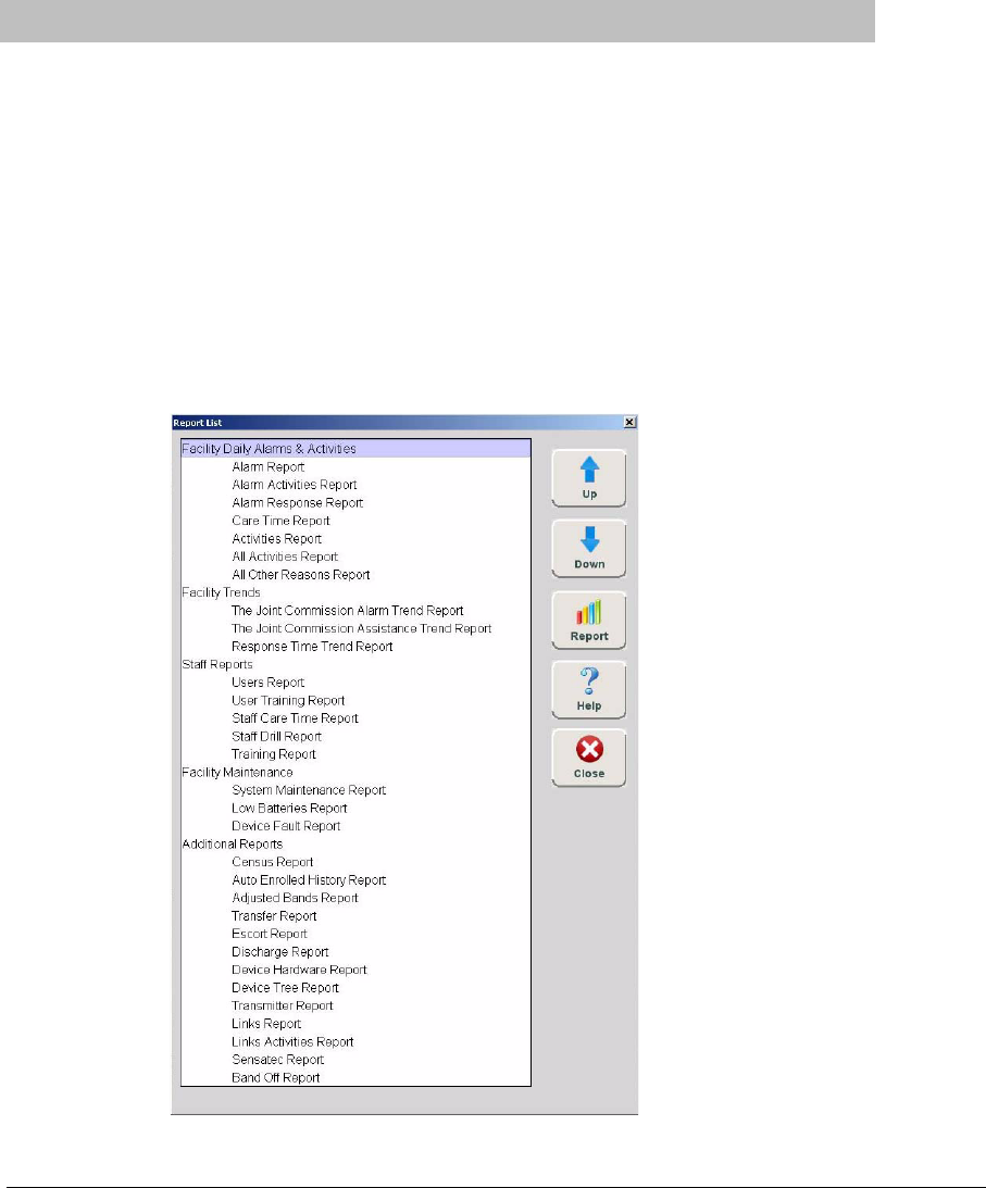
Series 7.0 Software (0510-1086-B) - User Guide 127
Chapter 5
Using System Reports
Introduction
This chapter provides detailed information about viewing and printing System Reports. In addition, it
provides detailed information about using and filtering reports. Following is a list of the types of reports that
are available in the software.
Reports
There are several Reports that enable you to view information about the activities of the system throughout
the day, week, or month. The Reports List is divided in sections. The sections depend on how your system is
configured. The following section provides detailed information about viewing, printing, saving, using, and
filtering Reports.
FIGURE 5.1: Example of a Reports List Window
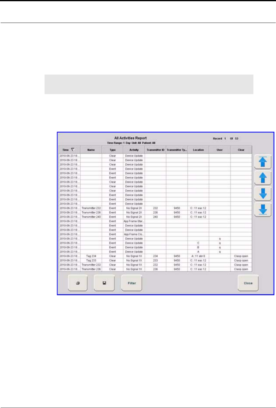
Chapter 5: Using System Reports
128 Series 7.0 Software (0510-1086-B) - User Guide
To view a report
1. Click Reports on the toolbar.
The Report List window appears.
2. In the Report List window, use the up and down arrows to select the report you want to run.
3. Click Report or double click on the selected report in the Report List.
The Report window appears with the report you requested.
FIGURE 5.2: Report Window
NOTE: The Reports List configuration will depend on your software application. The
available reports will depend on your licenses.
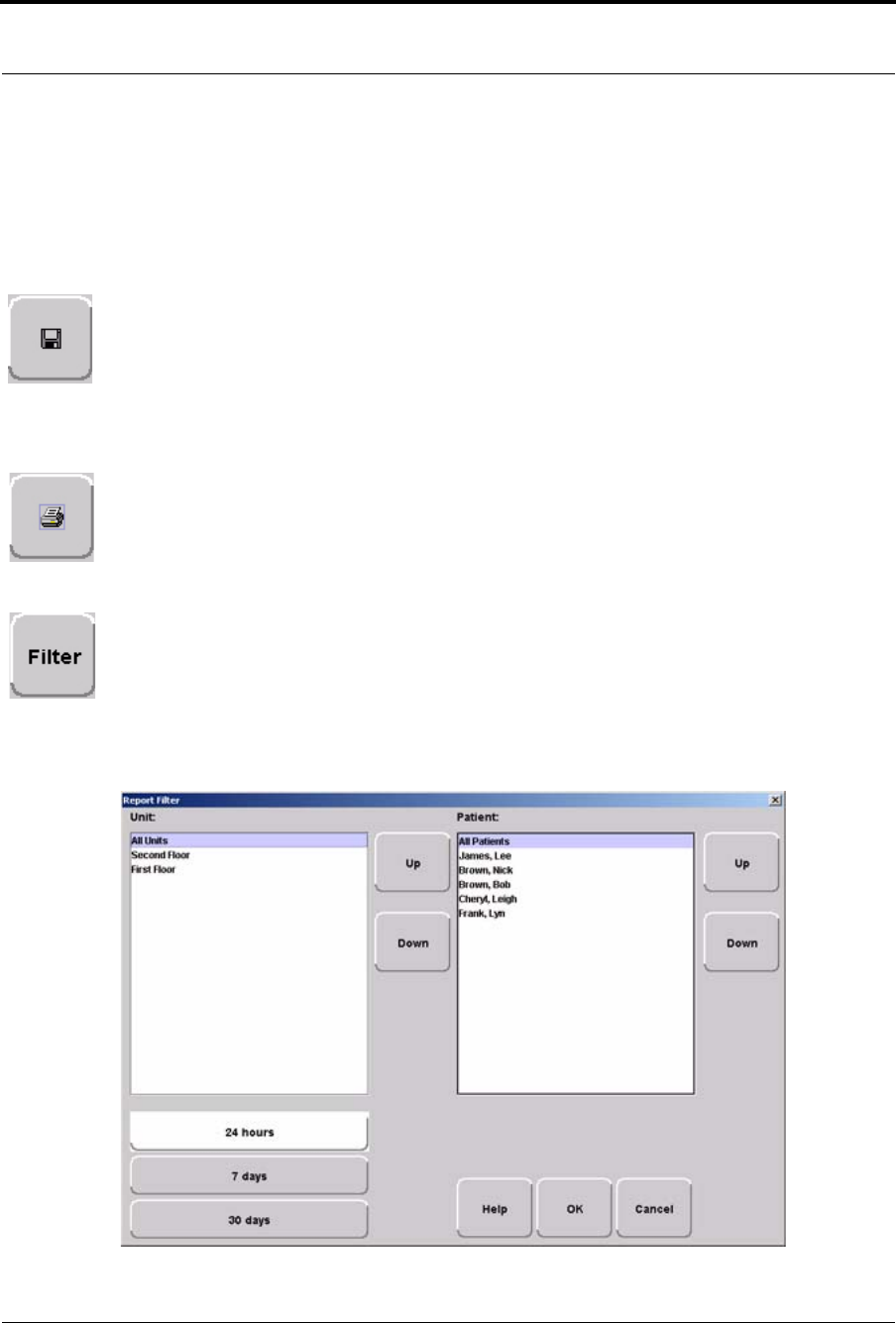
Series 7.0 Software (0510-1086-B) - User Guide 129
Introduction
Report Buttons
The Report buttons allow you to save a report, print a report, page through a report, and adjust the view of the
report. You can also select to Filter the report and Close the report window.
Save
A report can be saved directly to the Client computer(s). To save a report, click on the save
button located in the upper left corner of the toolbar. Type in a File Name and select a File of
Type from the drop-down list. It is recommended that you do not select HTML or XLS as
the file type due to anomalies that may occur in the saved report. Reports saved in XLS may
require additional formatting to view all text and align columns.
Print
A report can be printed directly from the generated report’s window. To print a report, click
on the print icon located in the upper left corner of the toolbar. The printer must be connected
and configured to the Client computer as a default printer.
Filter
By clicking the Filter button on the toolbar, you can select the criteria to run a specific report. Using the Filter
window, you can select which unit, which patient or asset, and what time frame you want to view (24 hours,
7 days, or 30 days). Once you select your criteria, click OK.
FIGURE 5.3: Report Filter Window
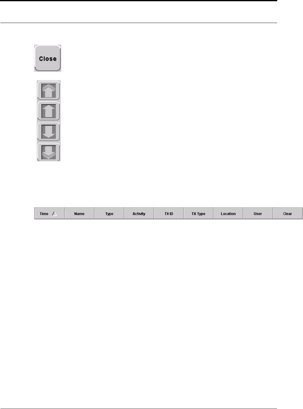
Chapter 5: Using System Reports
130 Series 7.0 Software (0510-1086-B) - User Guide
Close
Use this button to close the reports window.
Arrow Buttons
Use this button to page up to the previous page.
Use this button to scroll up to the previous entry on the page.
Use this button to scroll down to the next entry on the page.
Use this button to page down to the next page.
Sort By Headings
Many of the reports allow you to sort information by column heading. Click on the column heading to sort by
that specific heading. Click on the column heading a second time to reverse the sort order. Reports can be
saved or printed in the sorted format.
Series 7.0 Software (0510-1086-B) - User Guide 131
Introduction
Additional Joint Commission Report Buttons
Additional Report Buttons are found on selective Joint Commission Reports in the software. Following is an
explanation of these buttons.
First Page
Use this button to view the first page of a multiple page report.
Last Page
Use this button to view the last page of a multiple page report.
Next Page
Use this button to view the next page of the report.
Previous Page
Use this button to view the previous page of the report.
Actual Size
Use this button to adjust the view of the report to its actual size.
Fit Page
Use this button to fit the report to the size of the display screen.
Fit Width
Use this button to fit the report to the width of the display screen.
Zoom In
Use this button to maximize the view of the report by zooming in.
Zoom Out
Use this button to minimize the view of the report by zooming out.
Zoom Ratio
The zoom ratio corresponds to the size in which the report is currently being viewed. You can
also select to minimize or maximize a view by selecting the percent you which to adjust the
view in the Zoom Ratio drop-down list.

Chapter 5: Using System Reports
132 Series 7.0 Software (0510-1086-B) - User Guide
System Reports
The reports generated by the software have the same basic format. The header portion of the report identifies
the name of report. It also includes:.
Unit—the units included in the report.
Time Range—the range selected for the report.
Patient —the patients or assets included in the report.
Facility Name—the name of the facility.
Facility Address—the address of the facility.
The bottom portion of the report varies depending on the report. Following are details on each individual
report listed in the Report List.
Daily Alarms and Activities (Tracer Level 2)
Alarm Report
The Alarm Report lists all of the Red (high priority) alarms that occurred in the system within a specified
period of time. The Alarm Report includes:
Name—the name of the patient or asset to whom the transmitter is assigned.
Activity—the description of the alarm’s activity.
Time—the time of the alarm.
Transmitter ID—the identification number of the transmitter.
Transmitter Type—the type of transmitter
Location—the device that received the event.
Risk—the risk level assigned to the patient or asset.
By clicking the Filter button on the bottom of the Alarm report you can also select the criteria to run a
specific Alarm Report.

Series 7.0 Software (0510-1086-B) - User Guide 133
System Reports
Alarm Activities Report
The Alarm Activities Report lists all of the alarms that occurred in the system within a specified period of
time. The Alarm Activities Report includes:
Time—the time the alarm occurred.
Name—the name of the patient or asset to whom the transmitter is assigned.
Type—the type of event recorded.
Activity—the description of the alarm’s activity.
Transmitter ID—the identification number of the transmitter.
Transmitter Type—the type of transmitter that sent the signal.
Location—the device that received the event.
User—the staff member who cleared the event (when applicable).
Clear—the event reason used to clear the alarm (when applicable).
By clicking the Filter button on the bottom of the report, you can also select the criteria to run a specific
Alarm Activities Report.
Alarm Response Report
The Alarm Response Report enables you to gauge how your staff responds to system events. The Alarm
Response Report includes:
Name—the name of the patient or asset to whom the transmitter is assigned.
Transmitter ID—the identification number of the transmitter.
Location—the device, unit, and/or room that received the alarm.
Activity—the description of the event’s activity.
Event Time—when the event occurred.
Clear Time—when the event was cleared.
Response Time—the amount of time it took for the staff to respond to and clear the alarm at the
device.
Clear Reason—the event reason used to clear the alarm (when applicable).
By clicking the Filter button on the bottom of the report, you can also select the criteria to run a specific
Alarm Response Report.

Chapter 5: Using System Reports
134 Series 7.0 Software (0510-1086-B) - User Guide
Care Time Report (Code Alert only)
The Care Time Report enables you to gauge how your staff responds to system events. The Care Time
Report includes:
Name—the name of the patient or asset to whom the transmitter is assigned.
Care Time—the difference between the time the device was reset and the alarm was actually
cleared at the computer.
Reset Time—when the device was reset.
Clear Time—when the event was cleared at the computer.
Location—the device, unit, and/or room that received the alarm.
Activity—the description of the event’s activity.
Clear Reason—the event reason used to clear the alarm (when applicable).
User—the staff member who responded to the event.
By clicking the Filter button on the bottom of the report, you can also select the criteria to run a specific Care
Time Report.
Activities Report
The Activities Report lists all of the activities or events that have occurred in the system with respect to each
patient or asset.
The Activities Report includes:
Name—the name of the patient or asset to whom the transmitter is assigned.
Activity—the description of the event’s activity.
Type—the type of event recorded.
Time—the time of the event.
Transmitter ID—the identification number of the transmitter.
Transmitter Type—the type of transmitter.
Location—the device, unit and/or room that received the event.
User—the staff member who authorized or cleared the event (when applicable).
Risk—the risk level assigned to the patient or asset.
By clicking the Filter button on the bottom of the report, you can also select the criteria to run a specific
Activities Report.
NOTE: This report is sorted alphabetically by patient or asset and then by event time.

Series 7.0 Software (0510-1086-B) - User Guide 135
System Reports
All Activities Report
The All Activities Report lists all of the activities or events that have occurred in the system. The All
Activities Report includes:
Time—the time of the event or activity.
Name—the device, or the name of the patient or asset to whom the transmitter is assigned.
Type—the type of event recorded.
Activity—the description of the event’s activity.
Transmitter ID—the identification number of the transmitter.
Transmitter Type—the type of transmitter that sent the signal.
Location—the device that received the event.
User—the staff member who authorized the activity (when applicable).
Clear—the event reason used to clear the alarm (when applicable).
By clicking the Filter button on the bottom of the report you can select the criteria to run a specific All
Activities Report.
All Other Reasons Report
The All Other Reasons Report provides a summary of all the “other” reasons used when clearing an alarm.
“Other” are the reasons for alarm events that are manually entered by staff members when they clear alarms.
These reasons are reflected on the Joint Commission report as well. The All Other Reasons Report includes:
Time—the time of the event.
Name—the name of the patient or asset to whom the transmitter is assigned or the auto-enrolled
transmitter.
Type—the type of event recorded.
Activity—the description of the event.
Transmitter ID—the identification number of the transmitter involved.
Transmitter Type—the type of transmitter that sent the signal.
Location—the device that received the event.
User—the staff member who cleared the event (when applicable).
Clear—the manually entered reason (“other” reasons) for the event.
By clicking the Filter button on the bottom of the All Other Reasons Report, you can select the criteria to run
a specific report.
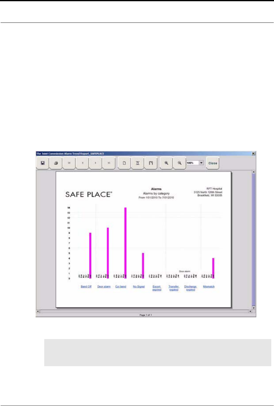
Chapter 5: Using System Reports
136 Series 7.0 Software (0510-1086-B) - User Guide
Facility Trends (Tracer Level 3)
Joint Commission reports are generated in three tiers, Trend, Trend Reason and Trend Reason Detail reports.
Alarms that occur when Enforce Joint Commission is “off” only populates the Trend report. Once Enforce
Joint Commission is activated, the Trend Reason and Trend Reason Detail reports will begin to populate.
Since alarms may have been generated before Enforce Joint Commission was activated, the numbers
between the Trend report and the Trend Reason and Trend Reason Detail reports may not match.
Joint Commission Alarm Trend Report
The Joint Commission Alarm Trend Report lists the different events that have occurred in the system in six-
month segments and then provides a bar graph to track the events. By clicking the Print icon, you can print
this report.
FIGURE 5.4: Joint Commission Alarm Trend Report
NOTE: If the Event cause is “Other,” go to the All Other Reasons Report and review the memo
field for more information. You can also select the “Other” hyper-link from any Joint
Commission Details Report.
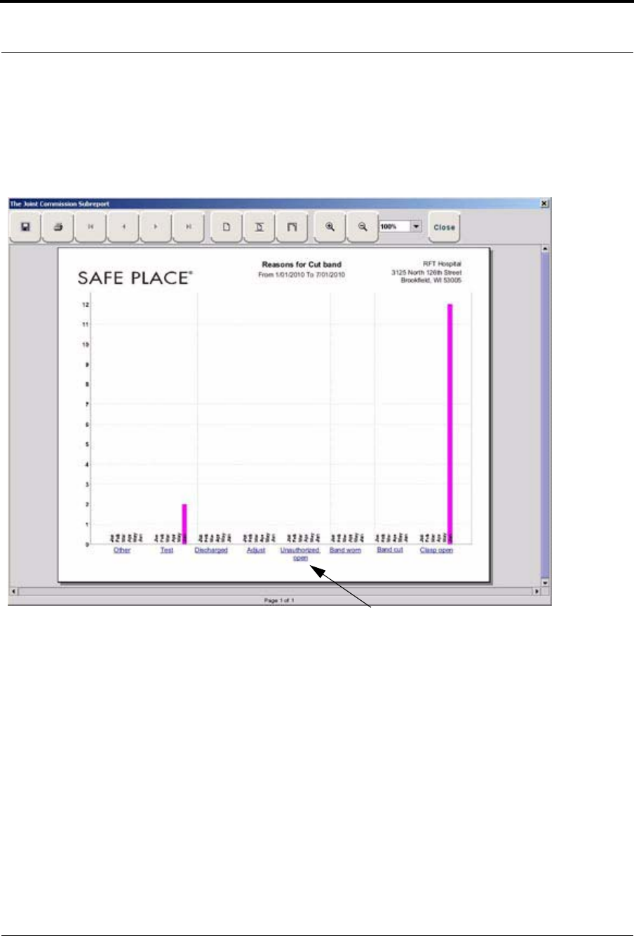
Series 7.0 Software (0510-1086-B) - User Guide 137
System Reports
Joint Commission Alarm Trend Reason Report
Click on the links at the bottom of the Joint Commission Alarm Trend Report to access the Joint Commission
Alarm Trend Reason Report. This report provides detailed information about the Event Causes that were
selected each time an Event was cleared.
FIGURE 5.5: Joint Commission Alarm Trend Reason Report
Joint Commission Alarm Trend Reasons Detail Report
Clicking on the Event Cause link at the bottom of the Joint Commission Alarm Trend Reason Report opens
the Reasons Detail Report that lists all events that went into the calculation of the Joint Commission Alarm
Trend Report. The Reasons Detail Report includes:
Date—the date and time the event occurred.
Response Time—the amount of time it took for the staff to respond and clear the event.
User—the staff member who responded to the event.
Location—the unit or room to which the device is assigned.
Transmitter—the identification number of the transmitter.
Name—the name of the device or the patient or asset to whom the device is assigned.
Event Cause
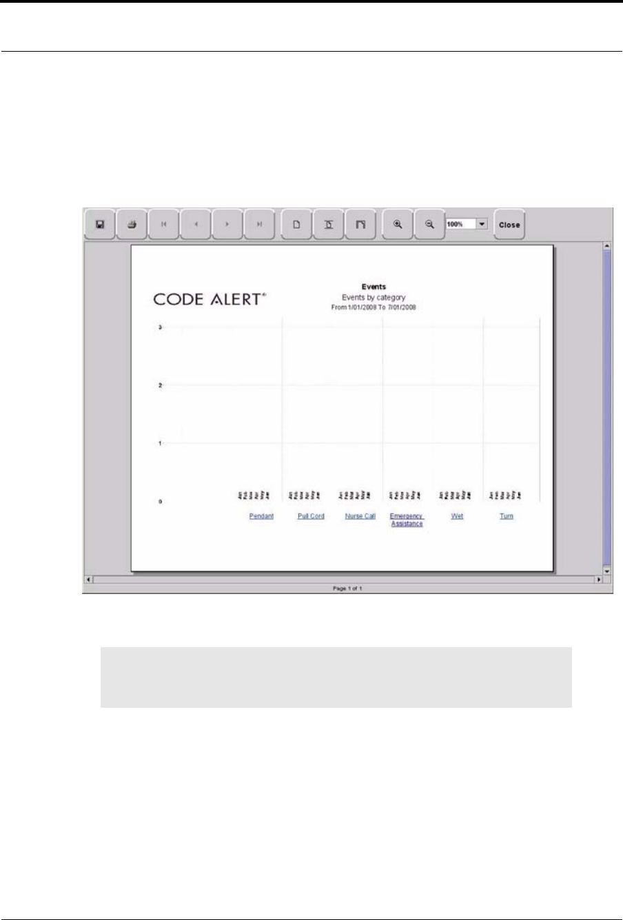
Chapter 5: Using System Reports
138 Series 7.0 Software (0510-1086-B) - User Guide
Joint Commission Assistance Trend Report
The Joint Commission Assistance Trend Report supports events generated by Emergency Assistance, Pull
Cord, Pendant, Fall Monitoring, and Incontinence devices. This report lists the different events for these
devices that have occurred in the system in six-month segments and then provides a bar graph to track the
events. By clicking the Print icon, you can print this report.
FIGURE 5.6: Joint Commission Assistance Trend Report
NOTE: If the Event cause is “Other,” go to the All Other Reasons Report and review the
memo field for more information. You can also select the “Other” hyper-link from any
Joint Commission Details Report.
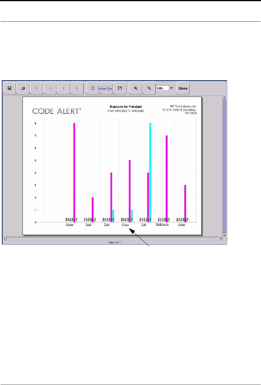
Series 7.0 Software (0510-1086-B) - User Guide 139
System Reports
Joint Commission Assistance Trend Reason Report
Click on the links at the bottom of the Joint Commission Assistance Trend Report to access the Joint
Commission Assistance Trends Reason Report. This report provides detailed information about the Event
Causes that were selected each time an Event was cleared.
FIGURE 5.7: Joint Commission Assistance Trend Reason Report
Joint Commission Assistance Trend Detail Report
Clicking on the Event Cause link at the bottom of the Reason Report opens a Reason Detail Report that lists
all events that went into the calculation of the Joint Commission Assistance Trend Report. The Reasons
Detail Report includes:
Date—the date and time the event occurred.
Response Time—the amount of time it took for the staff to respond and clear the event.
User—the staff member who responded to the event.
Location—the unit or room to which the device is assigned.
Transmitter ID—the identification number of the transmitter.
Name—the name of the device or the patient or asset to whom the device is assigned.
Event Cause
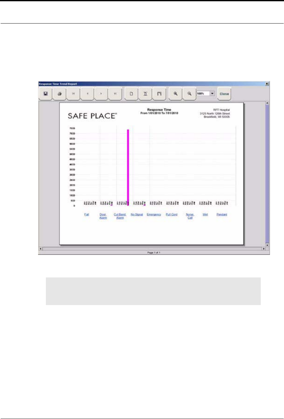
Chapter 5: Using System Reports
140 Series 7.0 Software (0510-1086-B) - User Guide
Response Time Trend Report
The Response Time Trend Report lists the response time for specific events that have occurred in the system
in six-month segments and then provides a bar graph to track the response time (in seconds) for those events.
FIGURE 5.8: Response Time Trend Report
NOTE: If the Event cause is “Other,” go to the All Other Reasons Report and review the
memo field for more information. You can also select the “Other” hyper-link from any
Joint Commission Details Report.
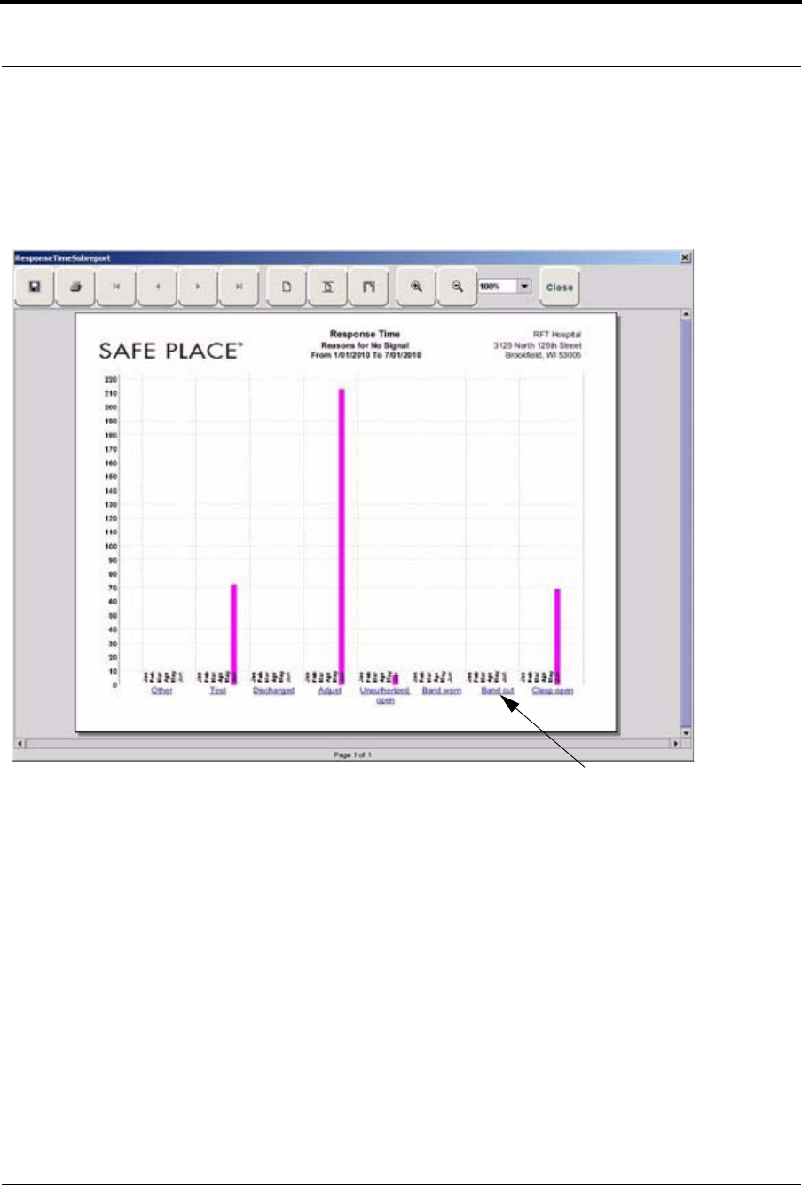
Series 7.0 Software (0510-1086-B) - User Guide 141
System Reports
Response Time Trend Reason Report
Click on the links at the bottom of the Response Time Trend Report to access the Response Time Trend
Reason Report. This report provides detailed information about the Event Cause that was selected each time
an Event was cleared.
FIGURE 5.9: Response Time Trend Reason Report
Response Time Trend Reasons Detail Report
Clicking on the Event Cause link at the bottom of the Reasons Report opens the Reasons Detail Report that
lists all events that went into the calculation of the Response Time Report. The Reasons Detail Report
includes:
Date—the date and time the event occurred.
Response Time—the amount of time it took for the staff to respond and clear the event.
User—the staff member who responded to the event.
Location—the unit or room to which the device is assigned.
Transmitter ID—the identification number of the transmitter.
Name—the name of the device or the patient or asset to whom the device is assigned.
Event Cause
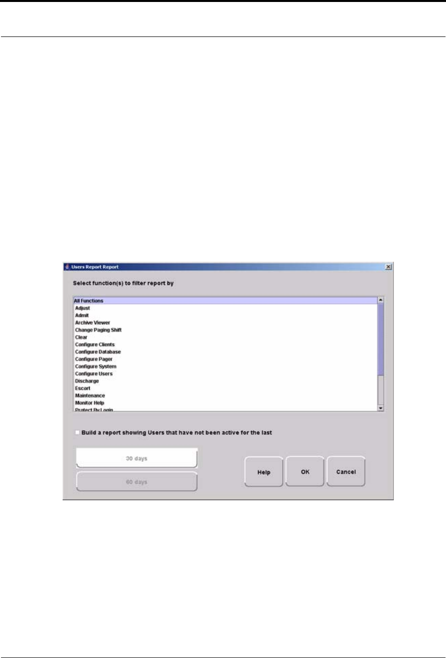
Chapter 5: Using System Reports
142 Series 7.0 Software (0510-1086-B) - User Guide
Staff Reports (Tracer Level 4)
Users Report
The User Report lists all of the staff members who are current users of the system. The User Report includes:
User—the name of the staff member.
Login—the login name of the staff member.
Assigned Functions— all functions assigned to the user.
Door Card Access— if the user has door card access.
By clicking the Filter button on the bottom of the Users Report, you can filter the report by assigned function
as well as build a report showing users that have not been active in the system for the last 30 days or
maximum of 60 days (the previous month plus the preceding number of days in the current month.
FIGURE 5.10: User Report Filter window

Series 7.0 Software (0510-1086-B) - User Guide 143
System Reports
User Training Report
The User Training Report tracks the use of the on-line user help feature by staff members with login. The
User Training Report includes:
Event Time—the time the user help file was opened.
User—the staff member who opened the user help file.
Topic—the topic or subject matter of the user help file.
Staff Care Time Report (Code Alert only)
The Staff Care Time Report enables you to gauge how your staff responds to system events. The Staff Care
Time Report includes:
User—the staff member who responded to the event.
Care Time—the difference between the time the event occurred and the time it was cleared at the
computer.
Care Started—the time the event occurred.
Care Completed—when the event was cleared at the computer.
Location—the device, unit, and/or room that received the alarm.
Activity—the description of the event’s activity.
Clear Reason—the event reason used to clear the alarm (when applicable).
Name—the name of the patient or asset to whom the transmitter is assigned.
By clicking the Filter button on the bottom of the report, you can also select the criteria to run a specific Staff
Care Time Report.

Chapter 5: Using System Reports
144 Series 7.0 Software (0510-1086-B) - User Guide
Staff Drill Report
The Staff Drill Report lists the drills performed by the staff members. The Staff Drill Report includes:
Time—the time of the staff drill.
Comments—the comments about the drill function performed.
User—the staff member who authorized and performed the drill.
Training Report
The Training Report identifies the training delivered to the patient upon admission. The Training Report
includes:
Name—the name of the patient.
Time—the date the delivery of training was entered into the system.
Handout Training—the date any handout was delivered to the patient.
Video Training—the date any video was shown to the patient.
Verbal—the time any verbal training was delivered to the patient.
User—the staff member who entered dates into the system.
Location—the unit to which the patient is assigned.
By clicking the Filter button on the bottom of the report, you can also select the criteria to run a specific Staff
Training Report.

Series 7.0 Software (0510-1086-B) - User Guide 145
System Reports
Facility Maintenance (Tracer level 5)
System Maintenance Report
The System Maintenance Report lists the maintenance functions performed on the system. The System
Maintenance Report includes:
Time—the time the maintenance was performed.
Comments—the comments about the maintenance function performed.
User—the service personnel who authorized and performed the maintenance.
Low Batteries Report
The Low Batteries Report provides a list of the transmitters and devices that currently have transmitted low
battery signals. The Low Batteries Report includes:
Name—the name of the device or the patient or asset to whom the transmitter is assigned.
Time—the time the low battery was recognized by the system.
Transmitter ID—the identification number of the transmitter.
Unit—the unit of the device or the patient or asset to whom the transmitter is assigned.
Device—the type of device reading the transmitter signal.
Room—the room of the device or the patient or asset to whom the transmitter is assigned.
Device Fault Report
The Device Fault Report provides detailed information about issues that occurred with system devices. This
Device Fault Report includes:
Time—the time the activity was reported.
Type—the type of event recorded.
Comport—the comport to which the device is assigned.
Physical Address—the network address of the device within the comport.
Location—the unit and room to which the device is assigned.
Last Checkin—the last time the device checked into the system.
Activity—the description of the event’s activity,.
By clicking the Filter button on the bottom of the Device Fault Report, you can select the criteria to run a
specific report.

Chapter 5: Using System Reports
146 Series 7.0 Software (0510-1086-B) - User Guide
Additional Reports
Census Report
The Census Report lists all of the patients, in the unit you are monitoring, that are currently admitted in the
system. This report is sorted alphabetically by unit and then by patient. The Census Report includes:
Name—the name of the patient.
Gender—the sex of the patient.
Unit—the unit to which the patient is assigned.
Room—the patient’s room number.
Transmitter ID—the identification number of the alarming band or Wander Management
transmitter assigned to the patient.
Admitted By—the staff member who performed the admission.
Risk—the risk level assigned to the patient.
Auto Enrolled History Report
The Auto Enrolled History Report lists the alarming band transmitters that were auto-enrolled. This report is
a history report; therefore, not all transmitters listed may be actively monitored by the system at the time of
the report. The report includes:
Enroll Time—the time when the transmitter was auto enrolled.
Location—the alarming band receiver (ABR) that picked up the auto-enroll and the unit the device
is assigned to.
Type—the type of event recorded.
Transmitter ID—the identification number of the transmitter.
By clicking the Filter button on the bottom of the Auto-Enrolled History Report, you can also select the
criteria to run a specific report.

Series 7.0 Software (0510-1086-B) - User Guide 147
System Reports
Adjusted Bands Report
The Adjusted Bands Report enables you to see which alarming band transmitter bands were adjusted. The
Adjust Bands Report includes:
Name—the name of the patient or asset to whom the transmitter is assigned.
Activity—the description of the band adjustment’s activity.
Type—the type of event recorded.
Time—the time of the event.
Transmitter ID—the identification number of the transmitter.
Location—the device that received the event.
User—the staff member who authorized the adjustment (when applicable).
Risk—the risk level assigned to the patient or asset.
By clicking the Filter button on the bottom of the Adjusted Bands Report, you can also select the criteria to
run a specific report.
Transfer Report
The Transfer Report lists all of the patients or assets who were transferred from one protected area to another
protected area. The Transfers Report includes:
Name—the name of the patient or asset.
Activity—the description of the transfer’s activity.
Type—the type of event recorded.
Time—the time of the event
Transmitter ID—the identification number of the transmitter (when applicable).
Location—the device that received the event.
User—the staff member who authorized the transfer (when applicable).
Risk—the risk level assigned to the patient or asset.
By clicking the Filter button on the bottom of the Transfer Report, you can select the criteria to run a specific
report.

Chapter 5: Using System Reports
148 Series 7.0 Software (0510-1086-B) - User Guide
Escort Report
The Escort Report lists all of the patients or assets who were escorted from a protected area and back to the
same protected area. The Escort Report includes:
Name—the name of the patient or asset to whom the transmitter is assigned.
Activity—the description of the escort’s activity.
Type—the type of event recorded.
Time—the time of the event.
Transmitter ID—the identification number of the transmitter.
Location—the device that received the event.
User—the staff member who authorized the escort (when applicable).
Risk—the risk level assigned to the patient or asset.
By clicking the Filter button on the bottom of the Escort Report, you can select the criteria to run a specific
report.
Discharge Report
The Discharge Report lists all of the patients or assets that were discharged from the system within a specified
period of time. The Discharge Report includes:
Name—the name of the patient or asset.
Activity—the description of the discharge’s activity.
Type—the type of event recorded.
Time—the time of the event.
Transmitter ID—the identification number of the transmitter (when applicable).
Location—the device that received the event.
User—the staff member who authorized the discharge (when applicable.)
Risk—the risk level assigned to the patient or asset.
By clicking the Filter button on the bottom of the Discharge Report, you can select the criteria to run a
specific report.

Series 7.0 Software (0510-1086-B) - User Guide 149
System Reports
Device Hardware Report
The Device Hardware Report lists all of the devices in the system. The report includes:
Description—the name of the device.
Type—the type of device.
Comport—the comport to which the device is assigned.
Physical Address—the network address of the device within the comport.
Location—the unit to which the device belongs
H/w Version—the device hardware version.
S/w Version—the device software version.
Linger—the linger time assigned to the EAC.
Device Tree Report (Code Alert only)
The Device Tree Report keeps a running history of 9600 Series devices that are enrolled in the system, even
if the device becomes disconnected from the system. The report includes:
Description—the name of the device.
Type—the type of device.
Comport—the comport to which the device is associated.
Path—the path that the device follows through the network to communicate with the Gateway.
Short Address—the address assigned by the Gateway and Routers on the network. Different
networks may use the same addresses.
MAC—the Media Access Control address of the device.
Location—the unit to which the device is assigned during configuration.
NOTE: If the device belongs to more than one unit, only the first unit (alphabetically) is
displayed.
NOTE: Device associations are not cleared from the Device Tree until the device
reassociates with the network or the Server is rebooted.

Chapter 5: Using System Reports
150 Series 7.0 Software (0510-1086-B) - User Guide
Transmitter Report
The Transmitter Report provides general details about transmitters admitted to the system. The Transmitter
Report includes:
Transmitter —the identification number of the transmitter.
Transmitter Type—the type of transmitter.
Name—the name of the patient or asset.
Location—the unit to which the device belongs.
Links Report
The Links Report provides general details about mothers and infants admitted to the system and currently
linked. The Link Report includes:
Link Transmitter ID—the ID number of the mother transmitter.
Transmitter ID—the identification number of the infant transmitter linked to the mother
transmitter.
Name—the name of the infant.
Unit Name—the unit to which the infant transmitter is associated.
Link Time—the time at which the infant was linked.
Links Activities Report
The Links Activities Report is a history report of all activities related to mother and infant transmitters that
were linked in the system. This report includes any activity that triggered an event for the linked transmitters.
The Links Activities Report includes:
Name—the name of the infant or mother.
Transmitter—the identification number of the infant transmitter involved.
Activity—the description of the event.
Time—the time of the event.
Mother Transmitter—the identification number of the mother transmitter involved.
Location—the device that received the event.
User—the staff member who cleared the event (when applicable).
By clicking the Filter button on the bottom of the Link Activities Report, you can select the criteria to run a
specific report.

Series 7.0 Software (0510-1086-B) - User Guide 151
Patient Reports
Sensatec Report
The Sensatec Report enables you to gauge how your staff responds to Sensatec events. The Sensatec Report
includes:
Name—the name of the patient to whom the control unit is assigned.
User—the staff member who responded to the event.
Location—the device, unit, and/or room that received the alarm.
Activity—the description of the event’s activity.
Event Time—when the event occurred.
Clear Time—when the event was cleared.
Care Time—the amount of time it took for the staff to respond and clear the white alarm.
Clear Reason—the event reason used to clear the alarm (when applicable).
By clicking the Filter button on the bottom of the report, you can also select the criteria to run a specific
Sensatec Report.
Patient Reports
Patient reports are specific to the individual patient. They are accessed from the Main tab of the patient’s
Admit Information window. The patient reports are as follows:
Review Info Report
The Review Info Report identifies admit information that was entered for the patient. The Review Info
Report includes the patient’s picture, if entered, and demographic information for the patient and the patient’s
contacts. It also includes the patient’s allergies, medication information, medical history information and any
special instructions that were entered.
Review Activity Report
The patient’s Review Activity Report lists all of the activities or events that have occurred in the system with
respect to the patient. The Review Activities Report includes:
Time—the time of the event.
Activity—the description of the event’s activity.
Type—the type of event recorded.
Reason—the event reason used to clear the alarm (when applicable).
User—the name of the patient to whom the transmitter is assigned.
Location—the device, unit and/or room that received the event.
Transmitter Type—the type of transmitter.
Transmitter ID—the identification number of the transmitter.
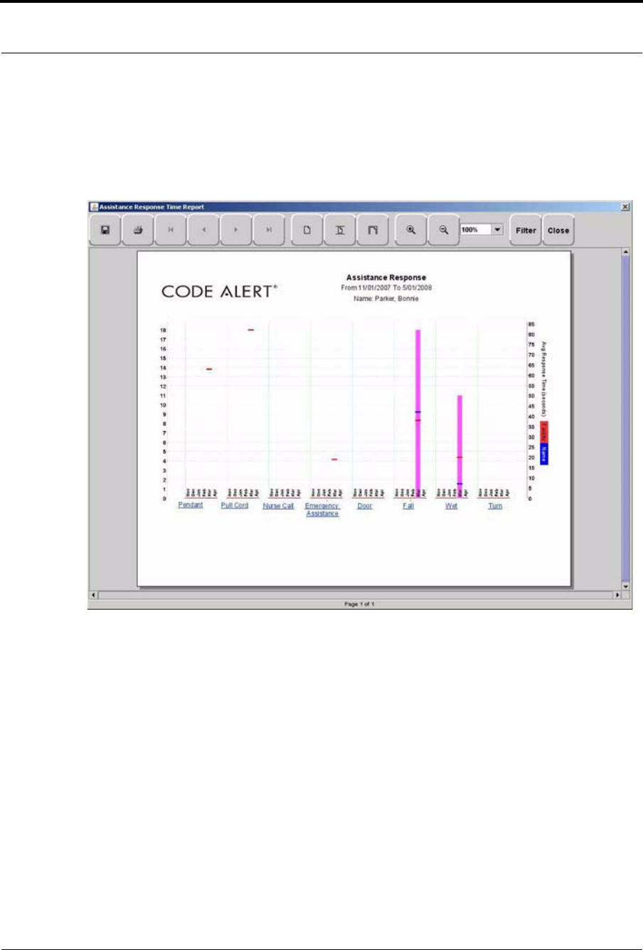
Chapter 5: Using System Reports
152 Series 7.0 Software (0510-1086-B) - User Guide
Review Response Report
The Review Response Report lists the response time for specific events that have occurred for the patient in
six-month segments and then provides a bar graph to track the number of events. The blue mark indicates the
events for the patient, the red mark indicate the average events for the facility.
FIGURE 5.11: Review Response Report
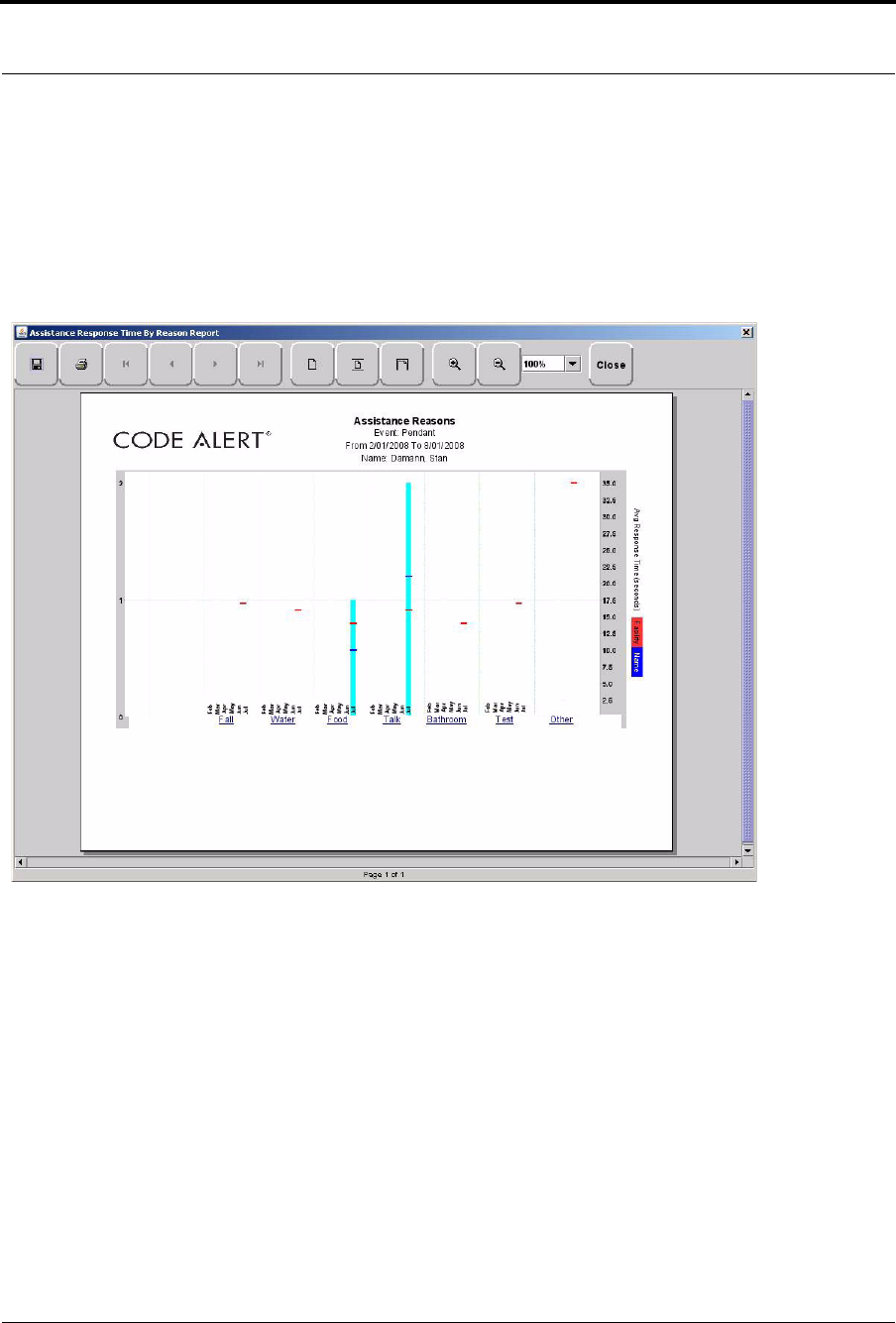
Series 7.0 Software (0510-1086-B) - User Guide 153
Patient Reports
Review Response Reason
By clicking on an event link at the bottom of the report, you can access the Response Reason Report. This
report provides detailed information about the Event Cause that was selected each time an Event was cleared
for the patient and then provides a bar graph to track the response time (in seconds) for those events. The blue
mark indicates the response time for the patient, the red mark indicate the average response time for the
facility.
FIGURE 5.12: Review Response Reason Reports

Chapter 5: Using System Reports
154 Series 7.0 Software (0510-1086-B) - User Guide
Review Response Reason Detail Report
Clicking on the Event Cause link at the bottom of the Reasons Report opens a Reason Detail Report that lists
all events that went into the calculation of the Review Response Report.
The Detail Report includes:
Date—the date and time the event occurred.
Response Time—the amount of time it took for the staff to respond and clear the event.
User—the staff member who responded to the event.
Transmitter ID—the identification number of the transmitter.
Name—the name of the device or the patient to whom the device is assigned.
Asset Reports
Asset reports are specific to the individual asset. The Asset Transmitter Report is accessed from the Assets
selection on the Menu bar of the Main window. The Asset Activities Report is accessed from the Main tab of
the Asset Admit Information window.
Asset Transmitter Report
The Asset Transmitter Report lists all the assets that are currently admitted in the system. The Asset
Transmitter Report includes:
Make—the assets manufacturer’s information.
Model—the model/description of the asset.
SN—the serial number of the asset.
Transmitter ID—the identification number of the transmitter assigned to the asset.
Location—the unit or room to which the asset is assigned.
Asset Activities Report
The Asset Activity Report lists all of the activities or events that have occurred in the system with respect to
the asset. The Asset Activities Report includes:
Time—the time of each event.
Activity—the description of the event’s activity.
Type—the type of event recorded.
Transmitter ID—the identification number of the transmitter.
Location—the device, unit and/or room that received the event.
User—the staff member who authorized or cleared the event (when applicable).
Reason—the event reason used to clear the alarm (when applicable).