R F Technologies FMFSZ24 Code Alert CA630 User Manual manual
R F Technologies Inc Code Alert CA630 manual
UserManual.wiki
>
R F Technologies
>
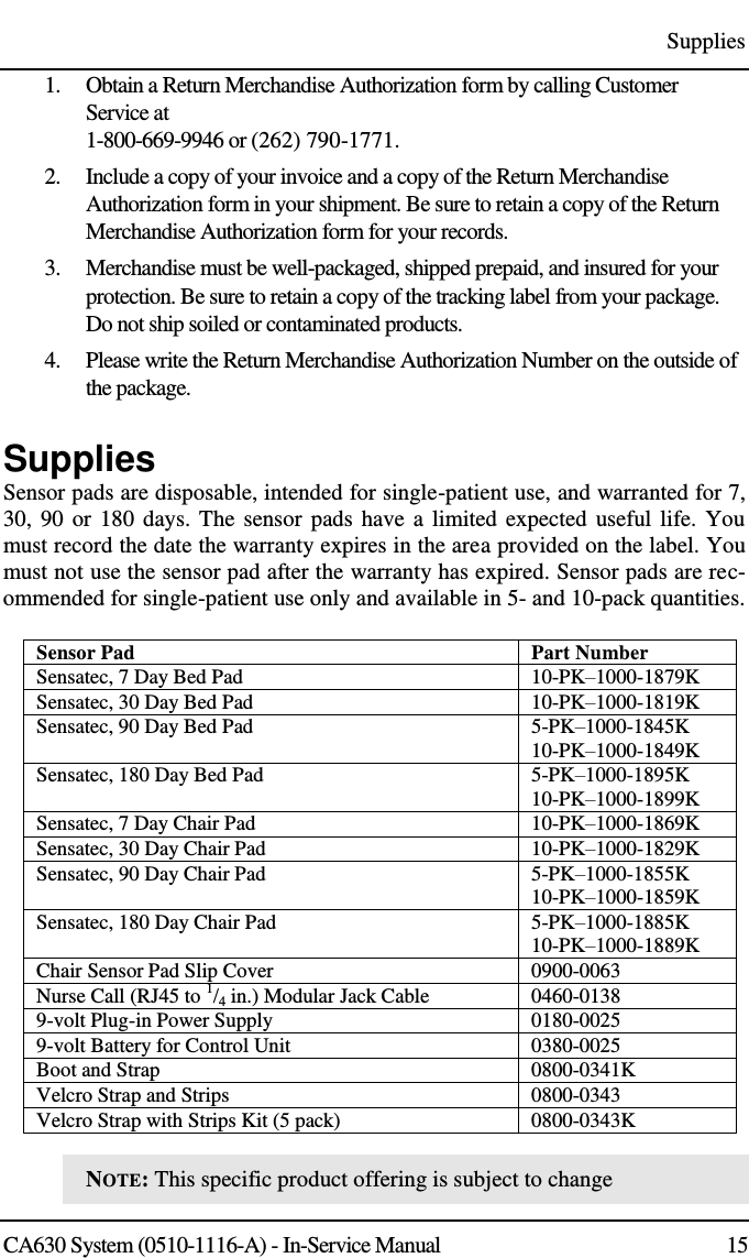
FMFSZ24 User Manual
manual
Navigation menu
Upload a User Manual
Namespaces
Wiki Guide
HTML
PDF
Info
Views
User Manual
Discussion / Help
Navigation