R F Technologies FMFSZ24 Code Alert CA630 User Manual manual
R F Technologies Inc Code Alert CA630 manual
manual

CA630 System
In-Service Manual
PN 0510-1116-A
Released 04/15/13
Users must read this Guide before using the Product.
3125 North 126th Street, Brookfield, WI 53005
Phone: 800.669.9946 Web: www.rtf.com

Copyright 2013 by RF Technologies, Inc.
All Rights Reserved. No Part of this work may be reproduced or copied in any form
or by any means without written permission from RF Technologies, Inc.
Classifications
The following information can be found on the back label of the CA630 control unit.
Do not immerse in water
Attention: Consult accompanying documents
Type BF Device
Direct Current
RF Symbol
Important Warnings
It is important for your facility to implement and enforce the following WARNINGS in order to
keep all equipment functioning properly. Disregarding the information and instructions in this
document is considered abnormal use and may result in injury or system failure.
WARNING
ACCESSORIES (SUPPLIES)—To ensure patient safety and proper operation of
equipment, use only parts and accessories manufactured or recommended by RF
Technologies, Inc. Parts and accessories not manufactured or recommended by RF
Technologies, Inc. may not meet the requirements of the applicable safety and
performance standards.
Failure to use the components and supplies specified by RF Technologies, Inc. may
result in equipment and/or system failure.
WARNING
EXPLOSION HAZARD—This device should not be used in the presence of flammable gas
mixtures. It should also not be used in oxygen enriched atmospheres.
WARNING
CHANGES OR MODIFICATIONS TO PRODUCT—RF Technologies prohibits
changes or modifications to the product; this may void the user’s authority to oper-
ate the equipment (FCC Code of Federal Regulations Title 47 Part 15.21).
WARNING
HIGH RISK FOR FALL—The CA630 System may not be suitable for patients who are at
“HIGH RISK FOR FALL.” Other monitoring measures may also be required. The Fall
Management System should not be a substitute for routine visual monitoring protocol by
caregiving personnel.
WARNING
INSTALLATION AND CONFIGURATION—It is the responsibility of the facility to
follow the installation instructions carefully, as outlined in the current Series Software
Administrator Guide, and to use the components and supplies specified by RF Technologies,
Inc. for all installations.
Failure to use the components and supplies specified by RF Technologies, Inc.
may result in equipment and/or system failure.
WARNING
INSTRUCTIONS FOR SET UP AND USE—It is the responsibility of the facility to
follow the instructions for set up and use carefully, as outlined in this manual, and to use
the components and supplies specified by RF Technologies, Inc. for set up and use. Do
not attempt to use extension cords or other equipment not supplied by RF Technologies,
Inc.
Failure to use the components and supplies specified by RF Technologies, Inc. may
result in equipment and/or system failure.
WARNING
PATIENT GENERATED ALARMS—Do not rely exclusively on patient generated
alarms for patient care and safety. The alarm function of equipment in the
possession of patients must be verified periodically and regular patient surveillance
is recommended.
WARNING
PATIENT MONITORING—The most reliable method of patient monitoring
combines close personal surveillance with correct operation of monitoring
equipment. It is the responsibility of the facility to periodically check on patients in
possession of RF Technologies, Inc.'s equipment (i.e. Pendants, Pull Cords, Control
Units) to mitigate risk of inappropriate use of equipment or strangulation and
stumbling hazards from cables and cords
WARNING
PRODUCT WARRANTIES—Failure to follow the Warnings and Cautions in this
guide voids any and all Product Warranties
WARNING
STATIC DISCHARGE—Do not touch the conductor portion of any conductor or
port. Damage to the device may result.
WARNING
STRANGULATIONS AND TRIPPING HAZARD—Due to the possibility of
strangulation, all cables and cords should be routed away from the patient’s throat. Cables
and cords must be routed in a way to prevent tripping hazards.
WARNING
SYSTEM INSPECTION—It is the responsibility of the facility to establish and
facilitate a regular inspection schedule for your system. RF Technologies, Inc.
recommends quarterly inspections of your system for safety and performance by a
qualified RF Technologies, Inc. representative.
To arrange for a quarterly inspection by RF Technologies, Inc., call our Technical
Support Department at (800)-669-9946 or (262) 790-1771.
Failure to provide regular inspection of these products may result in equipment and/or
system failure.
WARNING
SYSTEM MAINTENANCE AND TESTING—It is the responsibility of the facility
to establish and facilitate a regular maintenance schedule for your system, as
outlined in the current Series Software Administrator Guide. This includes regular
inspection, testing, and cleaning. RF Technologies, Inc. recommends monthly
maintenance and testing of your system. It is also recommended that your facility
keep records of maintenance and test completions.
Failure to provide regular maintenance and testing of these products may result in
equipment and/or system failure.
WARNING
SYSTEM WIRING—All permanent supply connections must be done in
accordance with National Electric Code, NFPA 70.
WARNING
USER TRAINING—Only users who have received adequate training on the use of the
system, as outlined in this manual, should use the system. It is the responsibility of the facility
to ensure all users have been trained.
Failure to adequately train employees may cause system failure due to user error. In
addition, incorrect use of the equipment may also result in system failure.
WARNING
WORN OR DAMAGED PARTS—If the control unit pads or cables are worn or damaged,
you must have the product serviced. For more information, see the section entitled “Service
and Return.”
WARNING
All RF Technologies transmitters, pendants and banding material “PRODUCT”
have been determined to be MR Unsafe as defined by ASTM F 2503-05. Use of
“PRODUCT” in a Magnetic Resonance Imaging system will cause injury to patients
and staff, MR system malfunction or “PRODUCT” malfunction. Do not bring
“PRODUCT” into the MR system area and follow your facilities policies to classify
and label “PRODUCT” as MR Unsafe.
CAUTION
DISPOSAL—At the end of their service life the products described in this manual,
as well as accessories (i.e. alkaline battery, disposable pads, etc.), must be disposed
of in compliance with all applicable federal, state and local guidelines regulating the
disposal of products containing potential environmental contaminants. Dispose of
the packaging material by observing the applicable waste control regulations.
Compliance
FCC
This device complies with Part 15 of the FCC Rules. Operation is subject to the following
two conditions: (1) This device may not cause harmful interference, and (2) this device
must accept any interference received, including interference that may cause undesired
operation.
RF Technologies prohibits changes or modifications to the product; this may void the
user’s authority to operate the equipment (FCC Code of Federal Regulations Title 47 Part
15.21).
Industry Canada
This device complies with Industry Canada license-exempt RSS standard(s). Operation is
subject to the following two conditions: (1) this device may not cause interference, and
(2) this device must accept any interference, including interference that may cause
undesired operation of the device.
Le présent appareil est conforme aux CNR d'Industrie Canada applicables aux appareils
radio exempts de licence. L'exploitation est autorisée aux deux conditions suivantes : (1)
l'appareil ne doit pas produire de brouillage, et (2) l'utilisateur de l'appareil doit accepter
tout brouillage radioélectrique subi, même si le brouillage est susceptible d'en
compromettre le fonctionnement.
Under Industry Canada regulations, this radio transmitter may only operate using an
antenna of a type and maximum (or lesser) gain approved for the transmitter by Industry
Canada. To reduce potential radio interference to other users, the antenna type and its
gain should be so chosen that the equivalent isotropically radiated power (e.i.r.p.) is not
more than that necessary for successful communication.
Conformément à la réglementation d'Industrie Canada, le présent émetteur radio peut
fonctionner avec une antenne d'un type et d'un gain maximal (ou inférieur) approuvé pour
l'émetteur par Industrie Canada. Dans le but de réduire les risques de brouillage
radioélectrique à l'intention des autres utilisateurs, il faut choisir le type d'antenne et son
gain de sorte que la puissance isotrope rayonnée équivalente (p.i.r.e.) ne dépasse pas
l'intensité nécessaire à l'établissement d'une communication satisfaisante.
FCC and IC Radiation Exposure Statement for Portable Devices
This equipment complies with FCC and IC radiation exposure limits set forth for an un-
controlled environment. This equipment is in direct contact with the body of the user
under normal operating conditions. This transmitter must not be co-located or operating
in conjunction with any other antenna or transmitter.
Product Warranty
RF Technologies, Inc. (herein referred to as “Seller”), warrants to the Buyer that during
the warranty period (defined below) the RF Technologies, Inc. products (herein referred
to as “Product”) will be free from manufacturing defects and will conform to the Seller’s
product specifications. The warranty period is defined as one of the following:
For product installed by Seller other than product identified below, warranty coverage is
provided for a period of twelve (12) months from the date of system “go live.” Warranty
coverage includes parts and labor during Seller’s standard business hours.
Fall Management pads are warranted for the period of days as indicated on the pad
label, or for a period not to exceed twelve (12) months from the date of shipment from
Seller.
All Sensatec Fall Management control units are warranted for a period of twenty-four
(24) months from the date of invoice.
Technical phone support for application assistance is available 24/7 during the warranty
period only.
This warranty is a limited warranty and it is the only warranty made by Seller. Buyer’s
sole remedy for any defect shall be repair or replacement, at Seller’s discretion, of any
part, returned to the Seller, shipment prepaid, and which upon examination is found by
Seller to be defective. Alternatively, Seller may, at its sole option, elect to refund the
purchase price paid for the defective product.
The criteria for all testing shall be based on Seller’s product specific test procedures.
Exclusions
Warranty coverage does not include, and Seller disclaims any liability for, any defect or
performance failure or deficiency (including failure to conform to product descriptions or
specifications) which results, in whole or in part, from (1) improper storage, handling,
misuse, maintenance, installation, or modification of the Product by Buyer, its employ-
ees, agents, or contractors, (2) absence of any product, component, or accessory recom-
mended by Seller, but omitted at Buyer’s direction, including but not limited to transmit-
ters and banding materials not tested and approved, (3) any design, specification, or in-
struction changed by Buyer, its employees, agents, or contractors, (4) failure to comply
with any applicable instructions or recommendations of Seller, including installation,
maintenance, testing, and training procedures, (5) physical damage occurring to transmit-
ters or other components after receipt and acceptance by Buyer, (6) integration or use of
any components, systems, process, software patches, software, or equipment not sold or
provided by Seller, (7) acts of God, acts of civil or military authority, fires, floods,
strikes, or other labor disturbances, war, riot, or other causes beyond the reasonable con-
trol of the Seller, (8) damage due to moisture, dust, dirt, and facility renovations, (9) un-
regulated and or out of specification electric power, temperature, humidity, or (10) radio
frequency interference in the Product’s operating environment. It is the Buyer’s responsi-
bility to make the necessary repairs to the building, power supply, or any sources of radio
frequency interference or noise that prevents the Product from operating properly.
This includes, but is not limited to, doorways, elevator drives, door motors, light ballasts,
door sensors, televisions, and computer monitors. The Buyer is responsible for labor and
expenses for investigation (i.e. noise assessment) that results in the finding of a condition
listed in warranty exclusions, (11) Buyer’s non performance of its responsibilities and
obligations. Non-compliance with remote connectivity requirements outlined in the
Terms and Conditions may result in loss of Buyer’s privileges to Seller’s technical phone
and warranty on-site support.
The preceding paragraphs set forth Buyer’s exclusive remedies and Seller’s sole liability
for claims based on the failure of the products to meet any warranty, whether the claim is
in contract, warranty, tort (including negligence and strict liability), or otherwise, and
however instituted, and upon the expiration of the applicable warranty period of such
liability shall terminate. IN NO EVENT SHALL SELLER BE LIABLE FOR ANY DI-
RECT, INDIRECT, SPECIAL, PUNITIVE, INCIDENTAL, OR CONSEQUENTIAL
DAMAGES OF ANY KIND RESULTING FROM THE USE, INABILITY TO USE,
OR FAILURE OF ANY OF SELLER’S PRODUCTS, WHETHER OR NOT SUCH
DAMAGES ARE FORESEEABLE OR IN CONTEMPLATION OF THE PARTIES,
EVEN IF SELLER HAS BEEN ADVISED OF THE POSSIBILITY OF SUCH DAM-
AGES.
EXCEPT AS EXPRESSLY SPECIFIED, THE PRODUCTS ARE PROVIDED “AS IS”.
THIS WARRANTY IS THE ONLY WARRANTY APPLICABLE TO THE PRODUCT
AND IS IN LIEU OF ANY OTHER WARRANTIES, EXPRESSED OR IMPLIED,
INCLUDING ANY IMPLIED WARRANTY OF MERCHANTABILITY, FITNESS
FOR A PARTICULAR PURPOSE, NON-INFRINGEMENT OR OF TECHNOLOGI-
CAL VALUE.

CA630 System (0510-1116-A) - In-Service Manual ix
Contents
Preface ................................................................................................................... 1
Overview.............................................................................................................................................. 1
Intended Audience ............................................................................................................................. 1
Additional Detailed Documentation ............................................................................................... 2
Contact Information ........................................................................................................................... 2
Chapter 1 .............................................................................................................. 3
System Overview ..................................................................................................... 3
System Overview ............................................................................................................................... 3
Control Unit ......................................................................................................................................... 4
Control Unit Indicators ...........................................................................................................4
Control Unit Buttons ...............................................................................................................5
Control Unit Jacks ...................................................................................................................5
Chapter 2 .............................................................................................................. 7
Set Up .................................................................................................................... 7
Setting Up The System ...................................................................................................................... 7
Fall Alert ...................................................................................................................................7
Nurse Call ................................................................................................................................8
Guidelines for Pressing the Hold Button ..............................................................................8
Chapter 3 ............................................................................................................ 9
Responding to Alarms.......................................................................................... 9
Fall Alert ...................................................................................................................... 9
Nurse Call ................................................................................................................................ 10
Low Battery ................................................................................................................................ 11
Chapter 4 ............................................................................................................ 13
Maintenance .......................................................................................................... 13
Caring For Your System ................................................................................................................. 13
Troubleshooting Your System ....................................................................................................... 13
Testing Your System ....................................................................................................................... 13
Operating and Storage Conditions ................................................................................................. 14
Pads ........................................................................................................................................ 14
Control Unit .......................................................................................................................... 14
Service and Return ........................................................................................................................... 14
Supplies .............................................................................................................................................. 15

Contents
x CA630 System (0510-1116-A) - In-Service Manual
This page intentionally left blank.

CA630 System (0510-1116-A) - In-Service Manual 1
Preface
Overview
This guide provides important information about the Code Alert 630 System, a
component of the Fall Management System. It provides detailed instructions
about using the Code Alert 630 as well as specific requirements.
Fall Management System
The Fall Management System provides restraint-free monitoring of a patient
who may try to leave a bed or chair without assistance. The Fall Management
System can be configured to interface with the software along with your facili-
ty's nurse call system. An Assistance Required alarm is activated in response to
a Fall Management System alert when interfaced with the applicable RF Tech-
nologies software.
WARNING: The Fall Management System may not be suitable for
patients who are "AT HIGH RISK FOR FALL." Other monitoring
measures may also be required. The Fall Management System should
not be a substitute for routine visual monitoring protocol by caregiv-
ing personnel.
Intended Audience
The CA630 System In-Service Manual is intended for caregivers who use the
CA630 Control Unit. It includes detailed information about System Set Up,
Responding to Alarms, and Caring for the system, including troubleshooting and
testing.

Preface
2 CA630 System (0510-1116-A) - In-Service Manual
Additional Detailed Documentation
Documentation for the 9450 System is available in Portable Document Format (PDF)
on the 9450 System Documentation CD-ROM. Please contact your RF Technologies
sales representative for replacement CD ROMs.
Contact Information
For more information about RF Technologies, Inc. products go to www.rft.com. For
technical support, contact (800) 669-9946 or (262) 790-1771. For questions or
comments about documentation, contact the RF Technologies Technical Publications
team at techpubs@rft.com.
CA630 System (0510-1116-A) - In-Service Manual 3
Chapter 1
System Overview
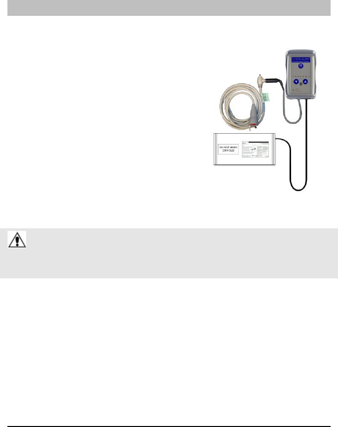
System Overview
The Code Alert 630 System has been designed
to assist in the area of Fall Alert. The control
unit, sensor pad and accessories function as a
stand-alone system or can be configured to
interface with the current Series Software. When
interfaced with the current Series Software, a Fall
alarm is activated in response to the applicable
event.
The CA630 can be supervised; a routine signal
is sent from the transceiver and if the signal is
not received by the system, a Device Fault event
is generated in the Event List at the Computer.
The default check-in time is 140 seconds.
WARNING: The CA630 System may not be suitable for patients who are
“AT HIGH RISK FOR FALL.” Other monitoring measures may also be
required. The CA630 System should not be a substitute for a routine visual
monitoring protocol by caregiving personnel.
Chapter 1: System Overview
4 CA630 System (0510-1116-A) - In-Service Manual
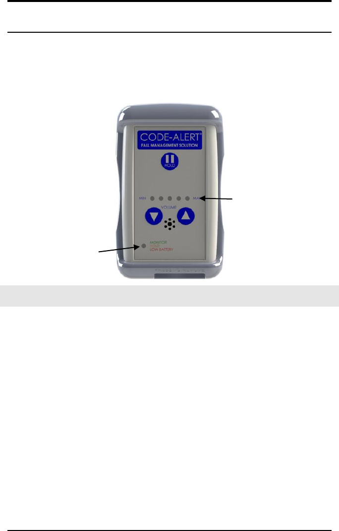
Control Unit
The control unit is designed to fit inside a silicone protective covering (Protective
Boot) to minimize damage from dropping and electro-static discharge. It also
includes an attachment strap for mounting the control unit to a bed or chair.
Status Indicator lights
Volume Indicator Lights
NOTE: The control unit should always be used inside the Protective Boot.
Control Unit Indicators
1. VOLUME INDICATOR LIGHTS
• As you adjust the volume, the green indicator light aluminate
to indicating the volume level.
2. STATUS INDICATOR LIGHTS
• GREEN (MONITOR ON)—The green light flashes every 2-seconds to
indicate the control unit is monitoring.
• ORANGE (HOLD)—The orange light flashes on and off to indicate the
control unit is in hold mode.
• RED (ALARMS)—The red light flashes on and off to indicate an alarm.
Alarms include Fall, Assist and Low Battery.
Control Unit
CA630 System (0510-1116-A) - In-Service Manual 5
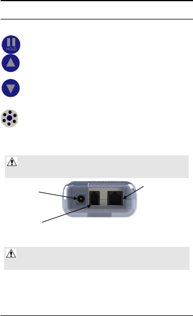
Control Unit Buttons
HOLD—Press this button to silence any alarm.
VOLUME UP—Press this button to turn the volume of the alarm
sound up.
VOLUME DOWN—Press this button to adjust the volume of the
alarm sound down.
BUZZER —Holes used for sound output. Do not cover the holes or insert
any objects in the holes for the Buzzer. This may prevent the caregiver from
hearing the alarm or it may damage the unit.
Control Unit Jacks
WARNING: Do not plug anything into the respective jacks other than
RF Technologies’ approved pads, cables and adapters (refer to the
Supplies section). Doing so will void the warranty.
1. Power Supply
3. Nurse Call
Adapter
2. Sensor Pad
1. POWER SUPPLY JACK—Connect the optional AC Adapter for continuous use.
WARNING: Use 9 V battery as a source of backup power when using
the optional AC Adaptor to reduce inadvertent power loss to the
control unit.
Chapter 1: System Overview
6 CA630 System (0510-1116-A) - In-Service Manual
2. NURSE CALL JACK —Connect the Nurse Call modular jack cable. Then plug
the Nurse Call cord set into the modular jack. Nurse Call monitoring starts when
the cord set is connected.
NOTE: The Nurse Call cord is gravity fed and must always be positioned upright as shown.
False nurse calls may occur if not positioned properly. Press the Hold button before
removing the Nurse Call modular jack cable to avoid getting a Tamper alarm.
3. SENSOR PAD
•

CA630 System (0510-1116-A) - In-Service Manual 7
Chapter 2
Set Up
Setting Up The System
NOTE: When positioning the control unit, ensure that the speakers holes and
indicator lights are not covered.
1. Visually inspect the sensor pad and sensor pad wires for damage. If damaged,
replace the damaged pad before proceeding.
2. Visually inspect the control unit for damage. Also inspect all other cords,
connectors, and sensors for damage. Replace if damaged.
3. Power the control unit by inserting a 9-volt alkaline battery into the battery
receptacle on the back of the control unit or connecting the plug-in power
supply. The unit will beep and the power indicator light will flash to show
operations.
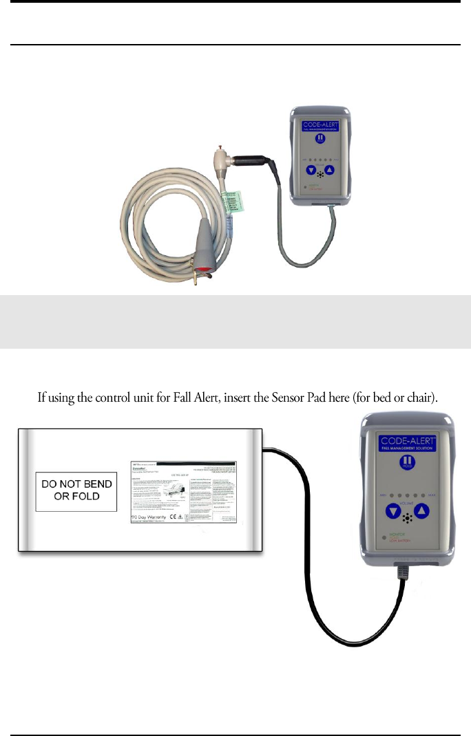
Fall Alert
1. Refer to the instructions on the Sensor Pad for placement of the pad on the bed
or chair.
2. Connect the sensor pad to the control unit and position the patient on the pad. The
control unit beeps once and the green light flashes every 2-seconds to indicate the
system is monitoring. If cords is damaged or disconnected, an alarm will sound at
the control unit.

Guidelines for Pressing the Hold button
CA630 System (0510-1116-A) - In-Service Manual 8
Nurse Call
To use the Nurse Call function:
1. Connect the Nurse Call modular jack cable to the control unit.
2. Insert the Nurse Call cord set into the modular jack. Nurse Call monitoring
starts when the cord set is connected.
3. Push the button on the Nurse Call cord set, an Assistance required alarm event
is reported in the Event List at the Client computer.
4. If the cord is disconnected, an alarm will sound at the control unit and at
remote indicators.
Guidelines for Pressing the Hold Button
1. Press the Hold button to initiate a 30-second alarm pause. Press the Hold
button again to cancel the 30-second pause.
2. The system turns off if no weight is applied to the pad after the 30-second
pause. The system reactivates once weight is applied to the pad.
3. To discontinue monitoring and avoid triggering an alarm, press the Hold
button. While the control unit is in the Hold mode you can safely remove the
patient from the Sensor pad and disconnect the Sensor pad and the Nurse Call
cord.
NOTE: While in Hold mode, an Assistance Required alarm (generated by pushing
the button on the Nurse Call cord) will not alarm at the unit but will post at the
Client computer and in the Reports.

CA630 System (0510-1116-A) - In-Service Manual 9
Chapter 3
Responding to Alarms
NOTE: If the Enforce JOINT COMMISSION feature is activated, you must select an
Event Cause once the alarming device has been reset. When you reset the alarming
device, the Red Alarm changes to a White Alarm in the Alarm Message Box. If JOINT
COMMISSION is not activated, the Alarm Message Box clears once the alarm is cleared
at the device
Fall Alert
When the patient’s weight is removed from the pad, the control unit beeps to alert
caregivers. A red status indicator light flashes in conjunction with the beeps for a
visual alert.
Proceed to the patient and secure them from potential fall situation.
Press the Hold button to stop the alarm. After HOLD is pressed, the orange light
flashes to indicate the system has been paused.
Assist the patient and return them to the sensor pad.
When the patient’s weight is re-applied to the sensor pad, the system begins
monitoring after the 30-second silence period. Or, press the Hold button again to
begin monitoring immediately.
If the Enforce JOINT COMMISSION feature is activated, you must select an
Event Cause. From the Client computer, click anywhere in the Fall Alarm Message
Box to access the Event Information window and select an Event Cause.
Chart the event per your facilities policies and procedures.

Nurse Call
CA630 System (0510-1116-A) - In-Service Manual 10
Nurse Call
When a patient pushes the button on the Nurse Call cord, an Assistance
Required alarm is generated. The control unit beeps twice every 2-seconds
to alert caregivers. A red status indicator light flashes in conjunction with
the beeps for a visual alert.
Proceed to the patient.
Press the Hold button to stop the alarm. After HOLD is pressed, the orange
light flashes to indicate the system has been paused.
Assist the patient.
Reset the Nurse Call button by pressing the small red reset pin located at the
base of the cord set.
The system begins monitoring after the 30-second silence period. Or, press
the Hold button again to begin monitoring immediately.
If the Enforce JOINT COMMISSION feature is activated, you must select an
Event Cause. From the Client computer, click anywhere in the Assistance Re-
quired Alarm Message Box to access the Event Information window and select
an Event Cause.
Chapter 3: Responding to Alarms
11 CA630 System (0510-1116-A) - In-Service Manual
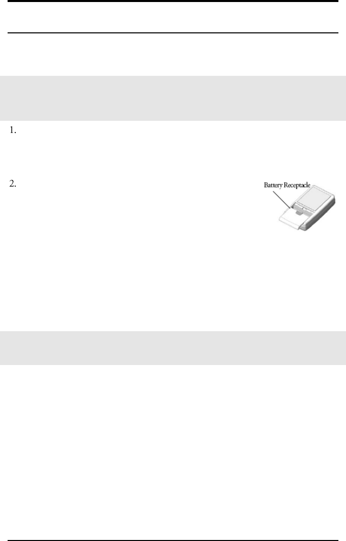
Low Battery
NOTE: A fully charged battery may last approximately 30 days when using one sensor
(i.e. Fall Alert). Additionally, monitoring activity and battery condition will shorten
operational life of the battery.
When the battery on the control unit is low, the red light flashes every 10-seconds,
the control unit beeps in conjunction with the flashes and a yellow Low Battery
alarm
appears on the Server.
Replace the battery immediately by inserting a 9-volt alka-
line battery.
• Remove the protective boot.
• Open the battery receptacle by pressing down and slid-
ing back the battery cover on the back of the control unit.
• Remove the old battery.
• Insert a new 9-volt alkaline battery into the control unit.
• Close the battery receptacle. If the control unit is attached to a sensor pad and
weight is applied, the green light flashes.
• Replace the protective boot.
NOTE: Remove the 9-volt alkaline battery from the control unit if the CA630 Fall
Management System will not be used for a prolonged period.

Chapter 3: Responding to Alarms
12 CA630 System (0510-1116-A) - In-Service Manual
This page intentionally left blank.

CA630 System (0510-1116-A) - In-Service Manual 13
Chapter 4
Maintenance
Caring For Your System
• Do not immerse the control unit in liquid; dry clean with alcohol wipe.
• Do not carry or move the control unit or the sensor pad by the cable(s).
• Remove the 9-volt alkaline battery from the control unit if the CA630 System
will not be used for a prolonged period.
Troubleshooting Your System
1. If the control unit issues a Fall Alert but the patient has not left the bed or chair:
Check the position of the sensor pad.
2. If the control unit does not issue an alert when the patient leaves the bed or chair:
• Check to see that the battery is properly connected and operational; the green
light on the control unit should blink every 2-seconds.
• Check to see that nothing is obstructing the buzzer holes.
• Check the position of the sensor pad. Refer to the section entitled “Setting Up
The System.”
• Check to see that the sensor pad plug is properly inserted in the Sensor jack on
the control unit.
Testing Your System
Test your CA630 System on a regular basis to verify proper operation.
To test your Fall Management Functionality
1. Follow the set up instruction in the section “Setting Up The System”
2. With the system monitoring weight on the pad, leave the bed or chair.
3. If the system is operating properly, an alert will sound at the control unit.
4. Repeat at several locations on pad.
Chapter 4: Maintenance
14 CA630 System (0510-1116-A) - In-Service Manual
To test your Nurse Call Functionality
1. Follow the set up instruction in the section “Setting Up The System”
With the system set up for Nurse Call, push the button on the Nurse Call cord set.
If the system is operating properly, an alert will sound at the control unit.
Operating and Storage Conditions
Pads
Pads must be stored properly to prevent damage. Store flat. Do not fold or store other items
on top of pads. Pads have a limited life; mark each pad with the WARRANTY EXPIRES
date.
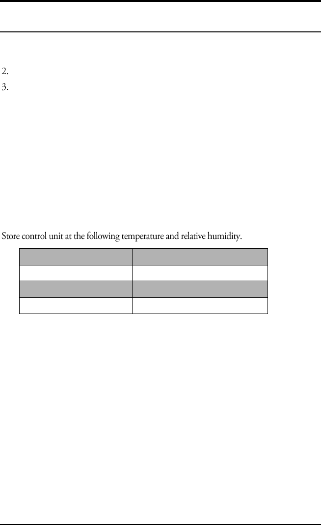
Control Unit
Operating Temperature
40 °F to 100 °F (4.4 °C to 38 °C)
Operating Humidity
0-95% non-condensing
Storage Temperature
32 °F to 120 °F (0 °C to 248 °C)
Storage Humidity
0-95% non-condensing
Service and Return
Do not attempt to service or repair the CA630 System; there are no serviceable parts
inside the control unit or the sensor pad. Any attempt at servicing or repairing the
product voids the warranty.
If you encounter problems with your equipment, please contact RF Technologies for
assistance. If your equipment appears to be defective, a technician will issue a Return
Merchandise Authorization Number so the unit may be returned.

Supplies
CA630 System (0510-1116-A) - In-Service Manual 15
1. Obtain a Return Merchandise Authorization form by calling Customer
Service at
1-800-669-9946 or (262) 790-1771.
2. Include a copy of your invoice and a copy of the Return Merchandise
Authorization form in your shipment. Be sure to retain a copy of the Return
Merchandise Authorization form for your records.
3. Merchandise must be well-packaged, shipped prepaid, and insured for your
protection. Be sure to retain a copy of the tracking label from your package.
Do not ship soiled or contaminated products.
4. Please write the Return Merchandise Authorization Number on the outside of
the package.
Supplies
Sensor pads are disposable, intended for single-patient use, and warranted for 7,
30, 90 or 180 days. The sensor pads have a limited expected useful life. You
must record the date the warranty expires in the area provided on the label. You
must not use the sensor pad after the warranty has expired. Sensor pads are rec-
ommended for single-patient use only and available in 5- and 10-pack quantities.
Sensor Pad
Part Number
Sensatec, 7 Day Bed Pad
10-PK–1000-1879K
Sensatec, 30 Day Bed Pad
10-PK–1000-1819K
Sensatec, 90 Day Bed Pad
5-PK–1000-1845K
10-PK–1000-1849K
Sensatec, 180 Day Bed Pad
5-PK–1000-1895K
10-PK–1000-1899K
Sensatec, 7 Day Chair Pad
10-PK–1000-1869K
Sensatec, 30 Day Chair Pad
10-PK–1000-1829K
Sensatec, 90 Day Chair Pad
5-PK–1000-1855K
10-PK–1000-1859K
Sensatec, 180 Day Chair Pad
5-PK–1000-1885K
10-PK–1000-1889K
Chair Sensor Pad Slip Cover
0900-0063
Nurse Call (RJ45 to 1/4 in.) Modular Jack Cable
0460-0138
9-volt Plug-in Power Supply
0180-0025
9-volt Battery for Control Unit
0380-0025
Boot and Strap
0800-0341K
Velcro Strap and Strips
0800-0343
Velcro Strap with Strips Kit (5 pack)
0800-0343K
NOTE: This specific product offering is subject to change
Caring For Your System
CA630 System (0510-1116-A) - In-Service Manual 16
This page intentionally left blank.