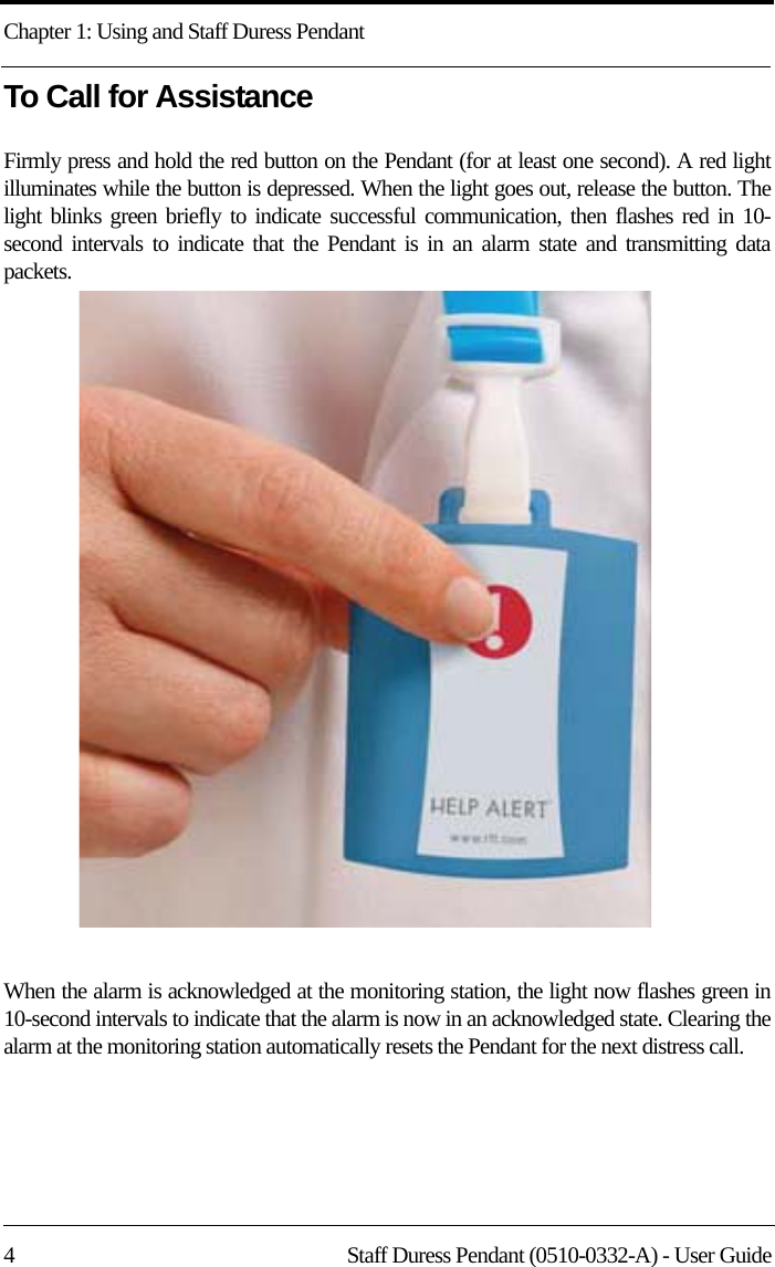
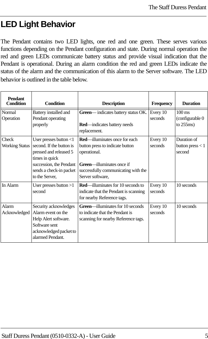
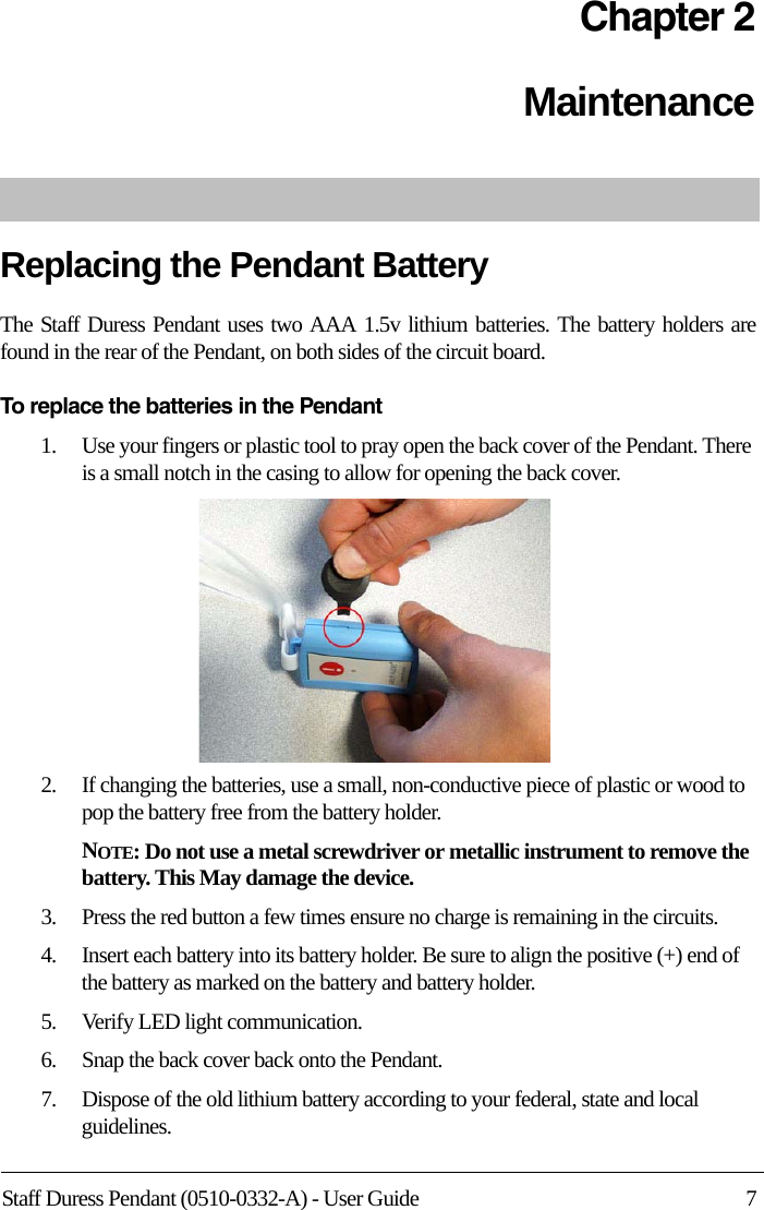
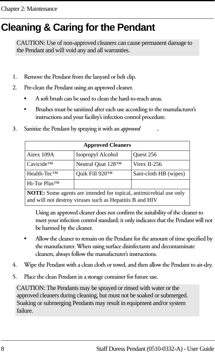
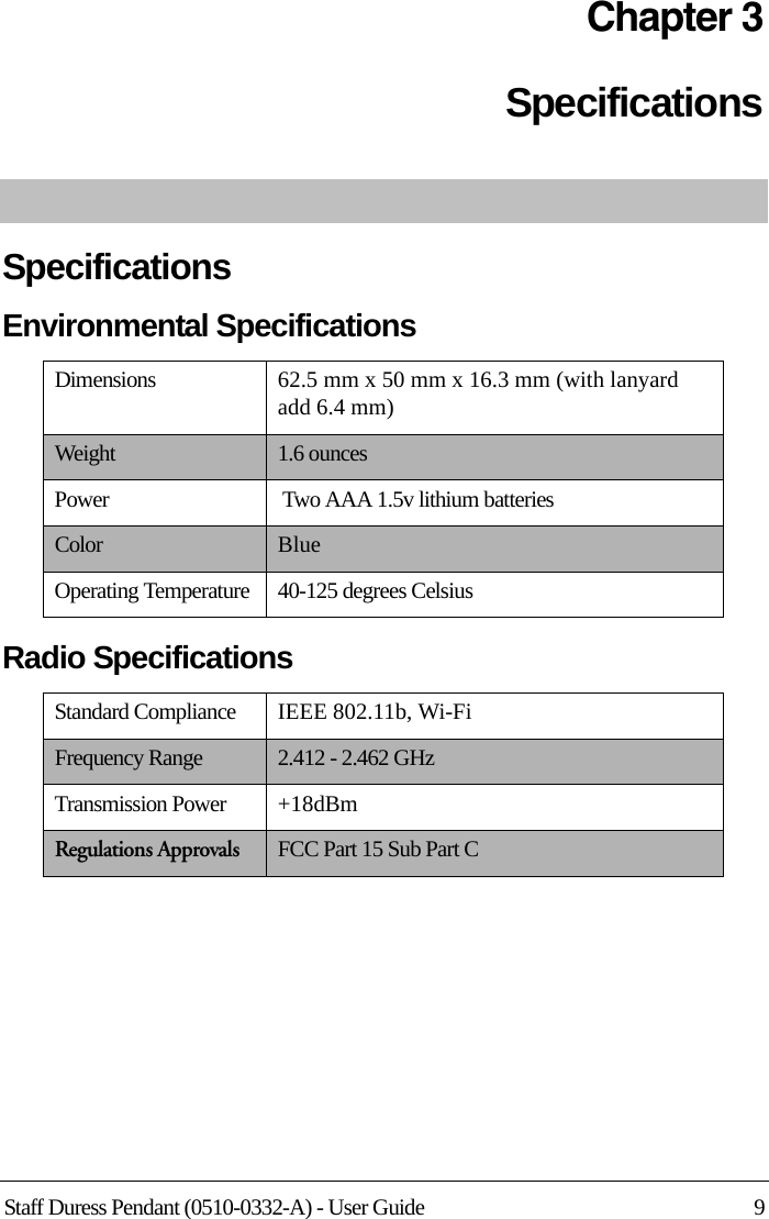
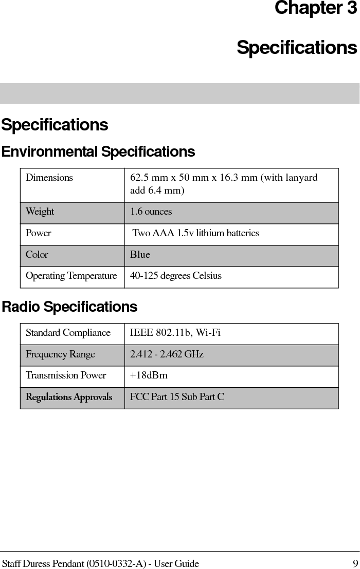
R F Technologies PNPT007 WiFi Pendant Location Tag User Manual 0510 0332 A Staff Duress Pendant

R F Technologies Inc WiFi Pendant Location Tag 0510 0332 A Staff Duress Pendant

Users Manual

®3125 North 126th Street, Brookfield, WI 53005Phone: 800.669.9946 Web: www.rft.com®®Help Alert® Emergency Call Solutions Staff Duress PendantUser GuidePN 0510-0332-AReleased 05/07/09Users must read this Guide before using the Product.
Copyright 2009 by RF Technologies, Inc.All Rights Reserved. No Part of this work may be reproduced or copied in any form or by any means without written permission from RF Technologies, Inc.
ComplianceFederal Communication Commission (FCC) Compliance This device complies with Part 15 of the FCC Rules. Operation is subject to the following two conditions: (1) this device may not cause harmful interference, and (2) this device must accept any interference received, including interference that may cause undesired operation of the device. This equipment generates, uses, and can radiate radio frequency energy and, if not installed and used in accordance with the instruction manual, may cause harmful interference to radio communications. Operation of this equipment in a residential area is likely to cause harmful interference in which case the user will be required to correct the interference at his own expense. Changes or modifications not expressly approved by the party responsible for compliance voids the user’s authority to operate the equipment. FCC and IC Radiation Exposure Statement for Portable Devices(For the Staff Duress Pendant model 1000-9100)This equipment complies with FCC and IC radiation exposure limits set forth for an uncontrolled environment. This equipment is in direct contact with the body of the user under normal operating conditions. This transceiver must not be co-located or operating in conjunction with any other antenna or transceiver.
Important WarningsIt is important for your facility to implement and enforce the following WARNINGS in order to keep all equipment functioning properly.INSTALLATION AND CONFIGURATION—It is the responsibility of the facility to follow the installation instructions carefully and to use the components and supplies specified by RF Technologies, Inc. for all installations.Failure to use the components and supplies specified by RF Technologies, Inc. may result in equipment and/or system failure.SYSTEM MAINTENANCE AND TESTING—It is the responsibility of the facility to establish and facilitate a regular maintenance schedule for your system. This includes regular inspection, testing, and cleaning. RF Technologies, Inc. recommend monthly maintenance and testing of your system. It is also recommended that your facility keep records of maintenance and test completions.Failure to provide regular maintenance and testing of these products may result in equipment and/or system failure.SYSTEM INSPECTION—It is the responsibility of the facility to establish and facilitate a regular inspection schedule for your system. RF Technologies, Inc. recommend quarterly inspections of your system for safety and performance by a qualified RF Technologies, Inc. representative.To arrange for a quarterly inspection by RF Technologies, Inc., call our Technical Support Department at (800)-669-9946 or (262) 790-1771.Failure to provide regular inspection of these products may result in equipment and/or system failure.USER TRANING—It is the responsibility of the facility to implement structured training procedures for all employees using the system. Only users who have received adequate training on the use of the system should use the system. Failure to adequately train employees may cause system failure due to user error. In addition, incorrect use of the equipment may also result in system failure.DISPOSAL—At the end of their service life the products described in this manual, as well as accessories (i.e. lithium batteries, banding material, disposable pads, etc.), must be disposed of in compliance with all applicable federal, state and local guidelines regulating the disposal of products containing potential environmental contaminants. Dispose of the packaging material by observing the applicable waste control regulations.PRODUCT WARRANTIES—Failure to follow the Warnings and Cautions in this guide voids any and all Product Warranties.
Staff Duress Pendant (0510-0332-A) - User Guide    iContentsPreface . . . . . . . . . . . . . . . . . . . . . . . . . . . . . . . 1Introduction . . . . . . . . . . . . . . . . . . . . . . . . . . . . . . .   1Help Alert E-Call Solution  . . . . . . . . . . . . . . . . . . . .  1Intended Audience . . . . . . . . . . . . . . . . . . . . . . . . . .   1Additional Detailed Documentation . . . . . . . . . . . .   2Contact Information  . . . . . . . . . . . . . . . . . . . . . . . . . 2Product Warranty   . . . . . . . . . . . . . . . . . . . . . . . . . . . 2Chapter 1 Using and Staff Duress Pendant . . . . . . . . 3Introduction . . . . . . . . . . . . . . . . . . . . . . . . . . . . . . .   3The Staff Duress Pendant  . . . . . . . . . . . . . . . . . . . .   3Wearing the Pendant . . . . . . . . . . . . . . . . . . . . . . . . .  3To Call for Assistance . . . . . . . . . . . . . . . . . . . . . . . .  4LED Light Behavior . . . . . . . . . . . . . . . . . . . . . . . . .  5Chapter 2 Maintenance. . . . . . . . . . . . . . . . . . . .  7Replacing the Battery  . . . . . . . . . . . . . . . . . . . . . . . . 7Cleaning & Caring for the Pendant. . . . . . . . . . . . .   8Chapter 3 Specifications . . . . . . . . . . . . . . . . . . .  9Specifications . . . . . . . . . . . . . . . . . . . . . . . . . . . . . .   9Environmental Specifications . . . . . . . . . . . . . . . . . .  9Radio Specifications. . . . . . . . . . . . . . . . . . . . . . . . . .  9
Contentsii    Staff Duress Pendant (0510-0332-A) - User GuideThis page intentionally left blank.
Staff Duress Pendant (0510-0332-A) - User Guide 1PrefaceIntroductionThis guide provides important information about the Staff Duress Pendant, a component of the Help Alert Emergency Call (E-Call) Solutions. It provides detailed instructions about using the pendant as well as specific requirements.Help Alert E-Call Solution The Help Alert E-Call Solutions allow doctors, nurses and other staff members to discreetly send a distress call when assistance is needed. The Help Alert software is displayed on a monitor with the facility floor plan visible for accurate location notification. The Help Alert E-Call Solution enables hospitals to secure the entire facility (i.e. staff areas, departments, etc.) with a customized application based on the PinPoint Real Time Location System (RTLS) platform.The Reference Tags form a peer-to-peer network and enables the Staff Duress Pendant to determine their exact location. The Help Alert E-Call Solution includes mobile access functions via a PDA. This component allows security personnel to receive visual and audible notifications and disable an alarm at the point of incident. Intended AudienceThe Staff Duress Pendant User Guide is intended for staff members who use the Pendant. It includes detailed information about using the Pendant, LED behavior and Pendant specifications.WARNING:  The Help Alert E-Call Solution is designed and intended to work in conjunction with a facility’s overall security program, including reasonable operating policies and procedures. The Help Alert E-Call Solution, by itself, cannot prevent security breaches.
: Preface2 Staff Duress Pendant (0510-0332-A) - User GuideAdditional Detailed DocumentationDocumentation for the Help Alert E-Call Solution is available in Portable Document Format (PDF) on the system’s documentation CD-ROM. Please contact your RF Technologies sales representative for replacement CR-ROMs.Contact InformationFor more information about RF Technologies, Inc. products go to www.rft.com. For technical support, contact (800) 669-9946 or (262) 790-1784. For questions or comments about documentation, contact the RF Technologies Technical Publications team at techpubs@rft.com.Product WarrantyProduct Warranty information can be found on the Help Alert E-Call Solution Documentation CD-ROM or with your original system proposal and invoice.
Staff Duress Pendant (0510-0332-A) - User Guide 3Chapter 1Using and Staff Duress PendantIntroductionThe Staff Duress Pendant is a wireless, mobile device that allows staff members to discreetly send a distress call when assistance is needed. When the system receives the call, the facility floor plan is displayed on the monitor for accurate location data. The Staff Duress Pendant sends periodic updates of its status to the Server via a check-in packet. The check-in interval is configurable between 30 seconds and 7.5 days. The Staff Duress PendantThe Staff Duress Pendant is lightweight and compact. It can be worn outwardly to maximize accessibility and used when emergency assistance is required. The Pendant is battery powered and provides location data based on an existing infrastructure and Reference tags when the Pendant’s button is pushed. Wearing the PendantThe Staff Duress Pendant is enclosed in a compact custom case. It can be worn around the neck on a lanyard or clipped to a belt.
Chapter 1: Using and Staff Duress Pendant4 Staff Duress Pendant (0510-0332-A) - User GuideTo Call for AssistanceFirmly press and hold the red button on the Pendant (for at least one second). A red light illuminates while the button is depressed. When the light goes out, release the button. The light blinks green briefly to indicate successful communication, then flashes red in 10-second intervals to indicate that the Pendant is in an alarm state and transmitting data packets. When the alarm is acknowledged at the monitoring station, the light now flashes green in 10-second intervals to indicate that the alarm is now in an acknowledged state. Clearing the alarm at the monitoring station automatically resets the Pendant for the next distress call.
The Staff Duress PendantStaff Duress Pendant (0510-0332-A) - User Guide  5LED Light BehaviorThe Pendant contains two LED lights, one red and one green. These serves various functions depending on the Pendant configuration and state. During normal operation the red and green LEDs communicate battery status and provide visual indication that the Pendant is operational. During an alarm condition the red and green LEDs indicate the status of the alarm and the communication of this alarm to the Server software. The LED behavior is outlined in the table below.Pendant Condition Condition Description Frequency DurationNormal OperationBattery installed and Pendant operating properlyGreen— indicates battery status OK.Red—indicates battery needs replacement.Every 10 seconds100 ms(configurable 0 to 255ms)Check Working StatusUser presses button <1 second. If the button is pressed and released 5 times in quick succession, the Pendant sends a check-in packet to the Server,Red—illuminates once for each button press to indicate button operational.Green—illuminates once if successfully communicating with the Server software,Every 10 secondsDuration of button press < 1 secondIn Alarm User presses button >1 second Red—illuminates for 10 seconds to indicate that the Pendant is scanning for nearby Reference tags.Every 10 seconds10 secondsAlarm AcknowledgedSecurity acknowledges Alarm event on the Help Alert software. Software sent acknowledged packet to alarmed Pendant.Green—illuminates for 10 seconds to indicate that the Pendant is scanning for nearby Reference tags.Every 10 seconds10 seconds
Chapter 1: Using and Staff Duress Pendant6 Staff Duress Pendant (0510-0332-A) - User Guide
Staff Duress Pendant (0510-0332-A) - User Guide 7Chapter 2MaintenanceReplacing the Pendant BatteryThe Staff Duress Pendant uses two AAA 1.5v lithium batteries. The battery holders are found in the rear of the Pendant, on both sides of the circuit board.To replace the batteries in the Pendant1.    Use your fingers or plastic tool to pray open the back cover of the Pendant. There is a small notch in the casing to allow for opening the back cover.2.    If changing the batteries, use a small, non-conductive piece of plastic or wood to pop the battery free from the battery holder.NOTE: Do not use a metal screwdriver or metallic instrument to remove the battery. This May damage the device.3.    Press the red button a few times ensure no charge is remaining in the circuits.4.    Insert each battery into its battery holder. Be sure to align the positive (+) end of the battery as marked on the battery and battery holder.5.    Verify LED light communication.6.    Snap the back cover back onto the Pendant.7.    Dispose of the old lithium battery according to your federal, state and local guidelines.
Chapter 2: Maintenance8 Staff Duress Pendant (0510-0332-A) - User GuideCleaning & Caring for the Pendant1.    Remove the Pendant from the lanyard or belt clip. 2.    Pre-clean the Pendant using an approved cleaner. • A soft brush can be used to clean the hard-to-reach areas. • Brushes must be sanitized after each use according to the manufacturer’s instructions and your facility’s infection control procedure.3.    Sanitize the Pendant by spraying it with an approved  .Using an approved cleaner does not confirm the suitability of the cleaner to meet your infection control standard; it only indicates that the Pendant will not be harmed by the cleaner.• Allow the cleaner to remain on the Pendant for the amount of time specified by the manufacturer. When using surface disinfectants and decontaminate cleaners, always follow the manufacturer’s instructions.4.    Wipe the Pendant with a clean cloth or towel, and then allow the Pendant to air-dry. 5.    Place the clean Pendant in a storage container for future use.CAUTION: Use of non-approved cleaners can cause permanent damage to the Pendant and will void any and all warranties.Approved CleanersAirex 109A      Isopropyl Alcohol Quest 256Cavicide™ Neutral Quat 128™ Virex II-256Health-Tec™    Quik Fill 920™ Sani-cloth HB (wipes)Hi-Tor Plus™NOTE: Some agents are intended for topical, antimicrobial use only and will not destroy viruses such as Hepatitis B and HIVCAUTION: The Pendants may be sprayed or rinsed with water or the approved cleaners during cleaning, but must not be soaked or submerged. Soaking or submerging Pendants may result in equipment and/or system failure.
Staff Duress Pendant (0510-0332-A) - User Guide 9Chapter 3SpecificationsSpecificationsEnvironmental SpecificationsRadio SpecificationsDimensions 62.5 mm x 50 mm x 16.3 mm (with lanyard add 6.4 mm)Weight 1.6 ouncesPower  Two AAA 1.5v lithium batteriesColor BlueOperating Temperature 40-125 degrees CelsiusStandard Compliance IEEE 802.11b, Wi-FiFrequency Range 2.412 - 2.462 GHzTransmission Power +18dBmRegulations Approvals FCC Part 15 Sub Part C
RF Technologies, Inc. 3125 North 126th Street, Brookfield, WI 53005 Phone: 800.669.9946 Web: www.rft.com

Navigation menu