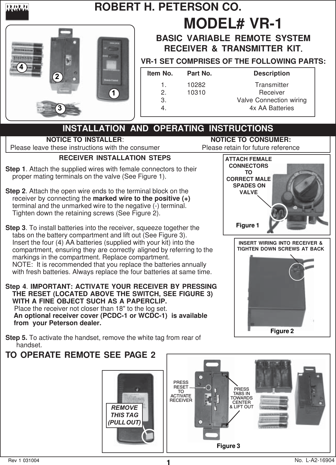
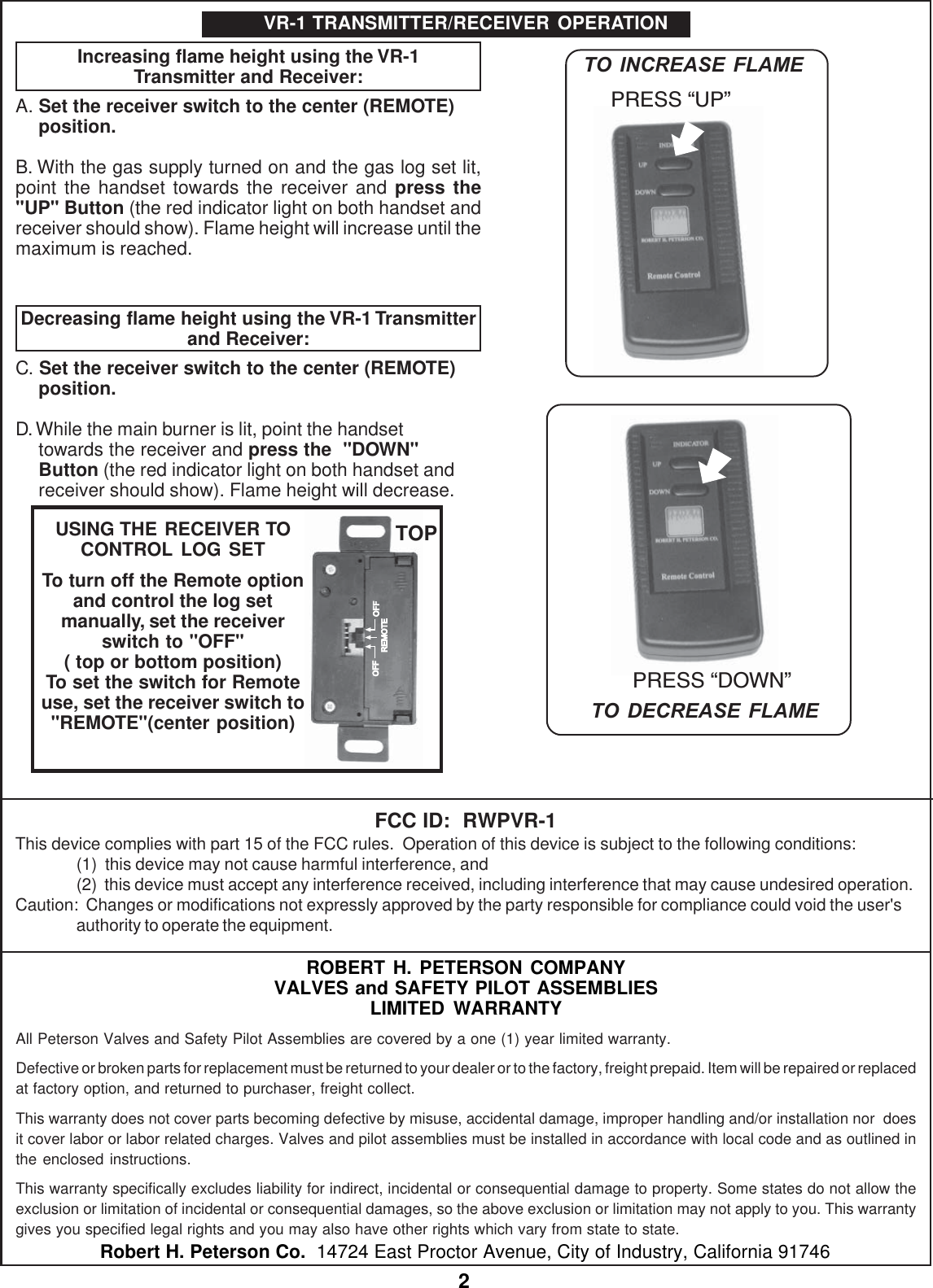
R H Peterson l VR-1 Remote Control Transmitter User Manual a2 169 pmd

R. H. Peterson Co.l Remote Control Transmitter a2 169 pmd

User Manual

1MODEL# VR-1BASIC VARIABLE REMOTE SYSTEMRECEIVER & TRANSMITTER KIT.VR-1 SET COMPRISES OF THE FOLLOWING PARTS:No. L-A2-16904Rev 1 031004RECEIVER INSTALLATION STEPSStep 1. Attach the supplied wires with female connectors to theirproper mating terminals on the valve (See Figure 1).Step 2. Attach the open wire ends to the terminal block on thereceiver by connecting the marked wire to the positive (+)terminal and the unmarked wire to the negative (-) terminal.Tighten down the retaining screws (See Figure 2).Step 3. To install batteries into the receiver, squeeze together thetabs on the battery compartment and lift out (See Figure 3).Insert the four (4) AA batteries (supplied with your kit) into thecompartment, ensuring they are correctly aligned by referring to themarkings in the compartment. Replace compartment.NOTE:  It is recommended that you replace the batteries annuallywith fresh batteries. Always replace the four batteries at same time.Step 4. IMPORTANT: ACTIVATE YOUR RECEIVER BY PRESSINGTHE RESET (LOCATED ABOVE THE SWITCH, SEE FIGURE 3)WITH A FINE OBJECT SUCH AS A PAPERCLIP. Place the receiver not closer than 18" to the log set.   An optional receiver cover (PCDC-1 or WCDC-1)  is available   from  your Peterson dealer.Step 5. To activate the handset, remove the white tag from rear of      handset.TO OPERATE REMOTE SEE PAGE 2ROBERT H. PETERSON CO.NOTICE TO INSTALLER:Please leave these instructions with the consumerINSTALLATION AND OPERATING INSTRUCTIONSNOTICE TO CONSUMER:Please retain for future referenceItem No. Part No. Description1. 10282 Transmitter2. 10310 Receiver3. Valve Connection wiring4. 4x AA BatteriesFigure 31243REMOVETHIS TAG(PULL OUT)OFF OFFREMOTEPRESSTABS INTOWARDSCENTER& LIFT OUTPRESSRESETTOACTIVATERECEIVERFigure 1ATTACH FEMALECONNECTORSTOCORRECT MALE SPADES ONVALVEINSERT WIRING INTO RECEIVER &TIGHTEN DOWN SCREWS AT BACKFigure 2
2ROBERT H. PETERSON COMPANYVALVES and SAFETY PILOT ASSEMBLIESLIMITED WARRANTYAll Peterson Valves and Safety Pilot Assemblies are covered by a one (1) year limited warranty.Defective or broken parts for replacement must be returned to your dealer or to the factory, freight prepaid. Item will be repaired or replacedat factory option, and returned to purchaser, freight collect.This warranty does not cover parts becoming defective by misuse, accidental damage, improper handling and/or installation nor  doesit cover labor or labor related charges. Valves and pilot assemblies must be installed in accordance with local code and as outlined inthe enclosed instructions.This warranty specifically excludes liability for indirect, incidental or consequential damage to property. Some states do not allow theexclusion or limitation of incidental or consequential damages, so the above exclusion or limitation may not apply to you. This warrantygives you specified legal rights and you may also have other rights which vary from state to state.Robert H. Peterson Co.  14724 East Proctor Avenue, City of Industry, California 91746Increasing flame height using the VR-1Transmitter and Receiver:A. Set the receiver switch to the center (REMOTE)position.B. With the gas supply turned on and the gas log set lit,point the handset towards the receiver and press the"UP" Button (the red indicator light on both handset andreceiver should show). Flame height will increase until themaximum is reached.Decreasing flame height using the VR-1 Transmitterand Receiver:C. Set the receiver switch to the center (REMOTE)position.D. While the main burner is lit, point the handsettowards the receiver and press the  "DOWN"Button (the red indicator light on both handset andreceiver should show). Flame height will decrease.VR-1 TRANSMITTER/RECEIVER OPERATIONPRESS DOWNPRESS UPTO INCREASE FLAMETO DECREASE FLAMEOFF OFFREMOTEUSING THE RECEIVER TOCONTROL LOG SETTo turn off the Remote optionand control the log setmanually, set the receiverswitch to "OFF"( top or bottom position)To set the switch for Remoteuse, set the receiver switch to"REMOTE"(center position)TOPFCC ID:  RWPVR-1This device complies with part 15 of the FCC rules.  Operation of this device is subject to the following conditions:(1)  this device may not cause harmful interference, and(2)  this device must accept any interference received, including interference that may cause undesired operation.Caution:  Changes or modifications not expressly approved by the party responsible for compliance could void the user'sauthority to operate the equipment.

Navigation menu