R H Peterson l VR-2 Remote Control Transmitter User Manual a2 170 pmd
R. H. Peterson Co.l Remote Control Transmitter a2 170 pmd
User Manual
1
4
6
2
1
5
MODEL# VR-2
DELUXE VARIABLE REMOTE SYSTEM
RECEIVER & TRANSMITTER KIT.
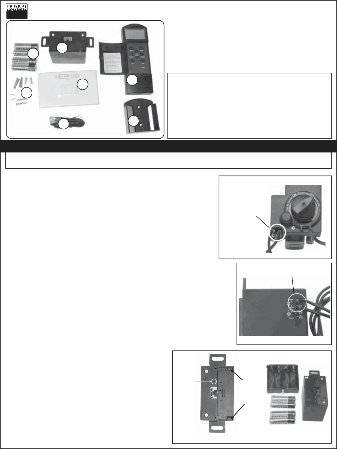
VR-2 SET
COMPRISES OF THE FOLLOWING PARTS:
No. L-A2-17004
Rev 1 031004
ROBERT H. PETERSON CO.
Item No. Part No. Description
1. 10281 Transmitter
2. 10277 Receiver
3. Valve Connection wiring
4. 4x AA Batteries
5. Remote holder
6. Wall Switch
7. Mounting screws
Figure 1
INSERT WIRING INTO RECEIVER &
TIGHTEN DOWN SCREWS AT BACK
Figure 2
ATTACH FEMALE
CONNECTORS
TO
CORRECT MALE
SPADES ON
VALVE
RECEIVER INSTALLATION STEPS
Step 1. Attach the supplied wires with female connectors to the proper
mating terminals on the valve (See Figure 1).
Step 2. Attach the open wire ends to terminal block marked "M"
on the receiver by connecting the marked wire to the
positive (+) terminal and the unmarked wire to the negative (-)
terminal. Tighten down the retaining screws (See Figure 2).
Step 3. To install batteries into the receiver, squeeze together the
tabs on the battery compartment and lift out (See Figure 3).
Insert the four (4) AA batteries (supplied with your kit) into the
compartment, ensuring they are correctly aligned by referring to the
markings in the compartment.Replace compartment.
NOTE: It is recommended that you replace the batteries annually
with fresh batteries. Always replace the four batteries at same time.
Step 4. IMPORTANT: ACTIVATE YOUR RECEIVER BY PRESSING
THE RESET (LOCATED ABOVE THE SWITCH, SEE FIGURE 3)
WITH A FINE OBJECT SUCH AS A PAPERCLIP.
Place the receiver not closer than 18" to the log set.
An optional receiver cover (PCDC-1 or WCDC-1) is available from
your Peterson dealer.
Step 5. To activate the handset, open the battery
compartment at rear, and remove the white tag.
To set up handset functions, follow instructions
on page 2, or the label on inside of handset cover.
Remote Functions available are:
Gas Log Set ON/OFF, Thermostatic control,
Timer control, Room Thermometer, Flame Height
control, and Sound control (when optional sound
device is connected)
An optional wall switch is supplied. See page 2
for installation instructions
TO OPERATE REMOTE SEE PAGE 2 Figure 3
NOTICE TO INSTALLER:
Please leave these instructions with the consumer
INSTALLATION AND OPERATING INSTRUCTIONS
NOTICE TO CONSUMER:
Please retain for future reference
3
7
OFF OFF
REMOTE
PRESS
TABS IN
TOWARDS
CENTER
& LIFT OUT
PRESS
RESET
TO
ACTIVATE
RECEIVER
2
Robert H. Peterson Co. 14724 East Proctor Avenue, City of Industry, California 91746
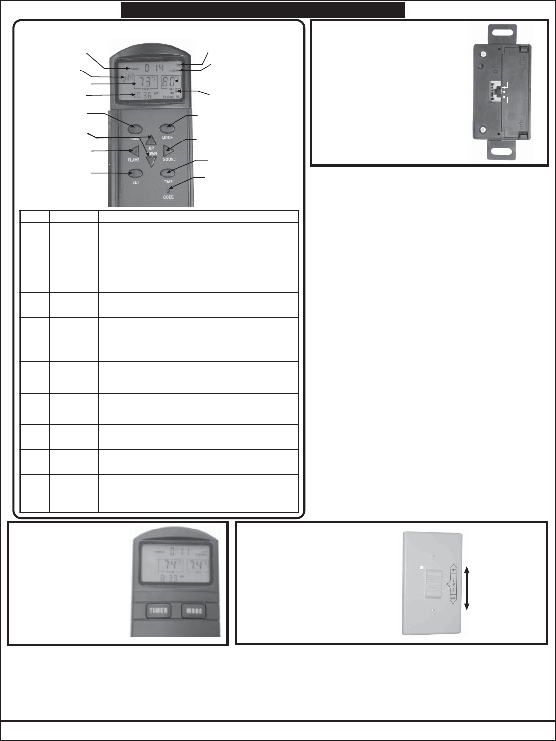
VR-2 TRANSMITTER/RECEIVER OPERATION
Thermostat set
temperature
ON/OFF indicator
Thermostat
indicator
Flame on/height
indicator
Sound on
indicator
Room
temperature
Time
Timer
indicator
MODE button
SOUND button
TIME button
CODE set button
(use paper clip)
TIMER
Button
Data Change
Buttons
SET Data
Button
FLAME control
Button
NOTTUBNOITCATLUSERNOITPONOITCATESGOLSAG
EDOM ECNOSSERP SNRUT NOTESDNAH NOTESGOLSNRUT
SSERP ECIWT
NOSNRUT TATSOMREHT LORTNOC
NWOD&PUESU TESOTSNOTTUB TATSOMREHT ERUTAREPMET
NOTESGOLSNRUT SSELSIPMETMOORFI .PMETTATSOMREHTNAHT FFOSNRUTTESGOL SIPMETMOORFI NAHTRETAERG .PMETTATSOMREHT
SSERP NEHW(ECNO )NO"OMREHT"
SNRUT FFOTESDNAH FFOTESGOLSNRUT
REMIT SSERP SPOTS/STRATS NOITPOREMIT
NWOD&PUESU OTSNOTTUB EMITSESAERCNI ETUNIM51NI OTPUSLAVRETNI SRUOH9
FFOTESGOLSNRUT SEHSINIFREMITNEHW
DNUOS SSERP
SEHCTIWS DNUOSLANOITPO YROSSECCA FFO/NO
NRUTYLLAUNAM:ETON NEHWFFODNUOS TESGOLFFOGNINRUT
EMALF SSERP SWOLLA FOLORTNOC THGIEHEMALF
OTNWOD/PUESU ROESAERCNI ESAERCED EMALF
YAWEHTLLADENRUTFI NRUTLLIW,NWOD FFOTESGOL
EMIT SSERP ECNO
KCOLCSWOLLA EBOT)RUOH( DEGNAHC
OTNWOD/PUESU GNITTESEGNAHC
SSERP ECIWT
KCOLCSWOLLA EBOT)SETUNIM( DEGNAHC
OTNWOD/PUESU GNITTESEGNAHC
TES SSERP
ATADSPEEK ROFGNITTES ,REMIT &TATSOMREHT KCOLC
USING THE REMOTE TO CONTROL LOG SET
OFF OFF
REMOTE
USING THE RECEIVER TO
CONTROL LOG SET
To turn off the Remote option
and control the log set
manually, set the receiver
switch to "OFF"
( top or bottom position)
To set the switch for Remote
use, set the receiver switch to
"REMOTE"(center position)
TOP
Move switch to
desired setting:
top = REMOTE OFF
(for manual control
of log set)
center = REMOTE ON
(allows remote use)
bottom = REMOTE OFF
(for manual control
of log set)
USING THE WALL SWITCH
To turn off remote option, set
wall switch to "OFF"
(top or bottom position)
To set for remote use, set wall
switch to "REMOTE"
(center position)
When operating remote, point
handset towards wall switch
NOTE: For quick
ON/OFF and/or
15 minuteTIMER,
press the MODE
and/or TIMER
buttons on handset
outer cover.
FCC ID: RWPRR-2
This device complies with part 15 of the FCC rules. Operation of this device is subject to the following conditions:
(1) this device may not cause harmful interference, and
(2) this device must accept any interference received, including interference that may cause undesired operation.
Caution: Changes or modifications not expressly approved by the party responsible for compliance could void the users
authority to operate this equipment.
WALL SWITCH MOUNT
1. Select a location for the Wall Switch near the
fireplace, up to 10 feet maximum from the
fireplace for the length of wiring supplied.
2. Cut out a clearance hole for direct wall or switch
box mounting. NOTE: Allow 3” deep (or greater)
space for the battery holder.
3. Tie 6" of chain (or a small weight) to a cord creating
a plumb line. Hang line from the location to the
top of wall baseboard. At this point (indicated by
the plumb line) drill a 1/2" to 3/4" hole.
4. Lower the line through the upper hole, within the
stud space, down to baseboard level. Pull weight
out of the lower hole using a stiff hooked wire (a
bent wire coat hanger works well) and remove
weight from the plumb line. Tie one end of the
Wire Cable to the plumb line and pull the line back
up through the Wall Switch location to expose
several inches of wire.
5. Connect the lower portion of wiring to the
connectors on the toggle switch on the valve, or
pine cone switch (see figure 1a and 1b).
6. Connect the other end of the wiring to receiver
terminals as shown in Figure 2. Insert 4 AA
batteries in the battery holder.
7. Attach the Wall Switch cover to the switch box
using the 1/4 inch machine screws supplied.