R STAHL HMI Systems GC667032 Trex Device Communicator User Manual UserManual
R. STAHL HMI Systems GmbH Trex Device Communicator UserManual
UserManual.wiki
>
R STAHL HMI Systems
>
GC667032 User Manual
>
UserManual
Contents
1.
UserManual_regulatoryStatements
2.
UserManual
UserManual
Navigation menu
Upload a User Manual
Namespaces
Wiki Guide
HTML
PDF
Info
Views
User Manual
Discussion / Help
Navigation

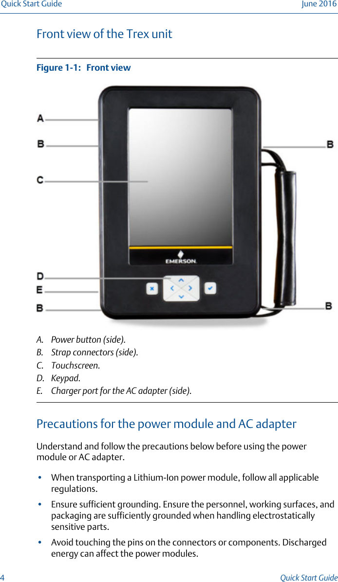
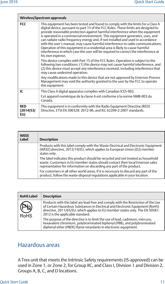
![2 Product certificationsSee the Trex Device Communicator website for the latest certificates,declaration of conformity, and approval information.Approved manufacturing locationR. STAHL HMI Systems GmbH - Cologne, GermanyLabelsEach Trex unit has a main unit label. An Intrinsically Safe (KL option) Trex unithas another label on the side. If the Trex unit does not have this label, it isconsidered non-IS approved.Certifications and approvalsEuropean directive information - CE complianceATEX(2014/34/EU)This equipment complies with the ATEX Directive. Applicable standards areEN 60079-0:2012 + A11:2013, EN 60079-11:2012, and EN 60079-26:2007.Certification No.: II 2 G (1GD) Ex ia [ia Ga] [ia Da IIC] IIC T4 Gb (-10°C < Ta < +50°C) 0158Electro MagneticCompatibility(EMC)2014/30/EUTested to the EN 61326-1:2006 and ETSI EN 301489-17:2002-08specification.Low Voltage Tested to the EN 61010-1:2001 + Corrigendum / Errata specification.International certificationsIECEx Certification No.:Ex ia [ia Ga] [ia Da IIC] IIC T4 (Tambient = 50°C)North American certificationsCanadianStandardsAssociation (CSA)Intrinsically Safe for use in Class I, Ex ia [ia Ga] [ia Da IIC] IIC T4 (-10°C < Ta <+50°C) hazardous locations when connected as indicated in the controldrawing.Quick Start Guide June 201610 Quick Start Guide](https://usermanual.wiki/R-STAHL-HMI-Systems/GC667032.UserManual/User-Guide-3106432-Page-10.png)
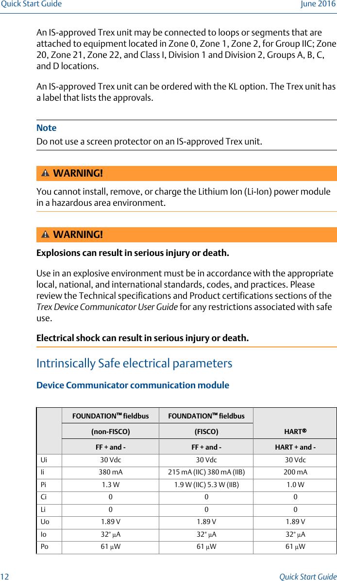
![FOUNDATION™ fieldbus FOUNDATION™ fieldbusHART®(non-FISCO) (FISCO)FF + and - FF + and - HART + and -Co 14.3 µF 14.3 µF 14.3 µFLo 100 mH 100 mH 100 mHDevice Communicator Plus communication modulemAinterfaceFOUNDATION™fieldbusHART®FOUNDATION™ fieldbus(non-FISCO) (FISCO)mAFF pwrand F- FF + and -HART +pwrHART +and -FF pwrand F - FF + and -Ui 30 Vdc 17.5 Vdc 30 Vdc 30 Vdc 30 Vdc 17.5 Vdc 30 VdcIi 200 mA 380 mA 380 mA 200 mA 200 mA 380 mA 215 mA (IIC)380 mA (IIB)Pi 1.0 W 1.3 W 1.3 W 1.0 W 1.0 W 1.3 W 1.9 W (IIC)5.3 W (IIB)Ci 0 231 nF 0 0 0 231 nF 0Li 0 0 0 0 0 0 0Uo0 17.31 V 1.89 V 25.69 1.89 V 17.31V 1.89 VIo 0 199 mA 32° µA 105 mA 1.9 mA 199 mA 32° µAPo0 0.94 W 61 µW 668 mW 3.6 mW 0.94 W 61 µWCo100 µF * nF 14.3 µF ** nF 14.3 µF * nF 14.3 µFLo100 mH * µH 100 mH ** mH 100 mH * µH 100 mH* FF pwr and F -Co [nf] 19 69 115Lo [µF] 100 50 30** HART + pwrCo [nf] 57 64 75 102Lo [µF] 1000 750 500 100June 2016 Quick Start GuideQuick Start Guide 13](https://usermanual.wiki/R-STAHL-HMI-Systems/GC667032.UserManual/User-Guide-3106432-Page-13.png)