R STAHL HMI Systems GC667032 Trex Device Communicator User Manual UserManual
R. STAHL HMI Systems GmbH Trex Device Communicator UserManual
Contents
- 1. UserManual_regulatoryStatements
- 2. UserManual
UserManual
Quick Start Guide
TREX-0045-0001_Draft_6716
June 2016
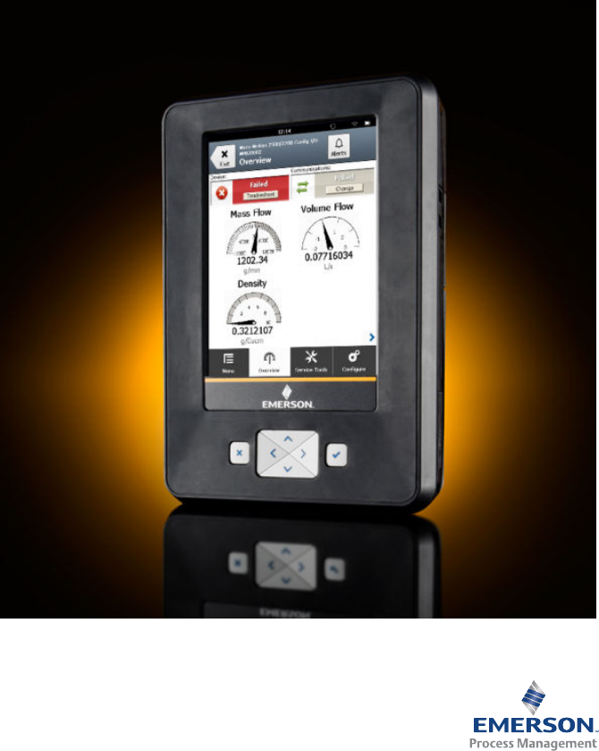
Trex™ Device Communicator
Quick Start Guide
Copyright and trademark information
©2016 Emerson Process Management. All rights reserved.
FOUNDATION™, HART® and WirelessHART® are marks of the FieldComm Group of Austin, Texas,
USA.
The Emerson logo is a trademark and service mark of Emerson Electric Co.
All other marks are the property of their respective owners.
Notice
Important
Read this manual before working with the Trex unit. For personal and system safety, and for optimum
product performance, thoroughly understand the contents before using or servicing this product.
For equipment service needs, contact the nearest product representative.
Important
This device complies with Part 15 of the FCC Rules. Operation is subject to the following two conditions:
(1) this device may not cause harmful interference, and (2) this device must accept any interference
received, including interference that may cause undesired operation.
WARNING!
WARNING - POTENTIAL ELECTROSTATIC CHARGING HAZARD - SEE INSTRUCTIONS.
AVERTISSEMENT - DANGER POTENTIEL DE CHARGES ÉLECTROSTATIQUES - VOIR INSTRUCTIONS
Quick Start Guide June 2016
2Quick Start Guide

1 Trex Device Communicator overview
The Trex unit supports HART® and FOUNDATION™ fieldbus devices, so you
can configure or troubleshoot in the field or on the bench. Electronic Device
Description Language (EDDL) technology enables the Trex unit to
communicate with a variety of devices independent of device manufacturer.
Depending on the attached communication module, the Trex unit lets you:
•Configure HART and FOUNDATION fieldbus devices.
•Power one HART or FOUNDATION fieldbus device.
•Measure current and voltage.
•Perform diagnostics on a 4-20 mA current loop or FOUNDATION fieldbus
segment.
The Trex unit includes a color LCD touchscreen, a Lithium-Ion power module
(battery pack), a processor, memory components, and optional
communication modules.
Note
When the Trex unit communicates with devices, follow all standards and
procedures applicable to the location. Failure to comply may result in
equipment damage and/or personal injury. Understand and comply with the
sections in this manual.
Precautions for the Trex unit
Before operating the Trex unit, ensure the following:
•The Trex unit is not damaged.
•The power module is securely attached.
•All screws are sufficiently tightened.
•The communication terminal recess is free of dirt and debris.
•The communication module is securely attached.
Note
Do not use a screen protector on an IS-approved Trex unit.
June 2016 Quick Start Guide
Quick Start Guide 3
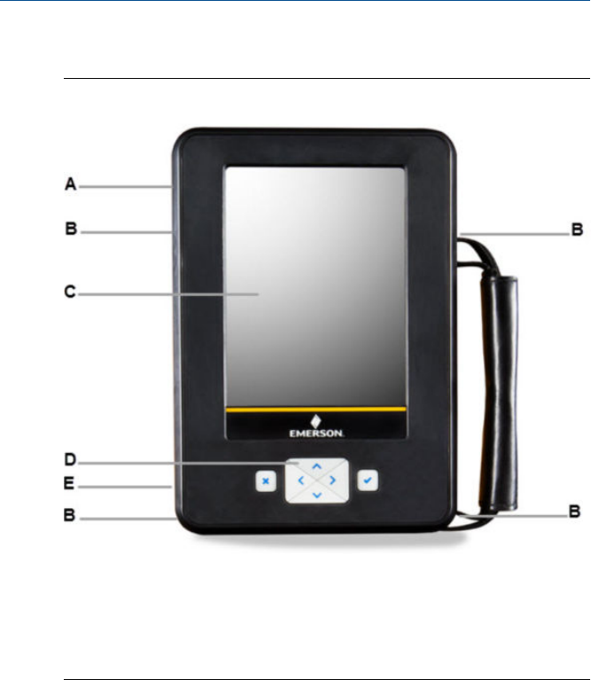
Front view of the Trex unit
Front viewFigure 1-1:
A. Power button (side).
B. Strap connectors (side).
C. Touchscreen.
D. Keypad.
E. Charger port for the AC adapter (side).
Precautions for the power module and AC adapter
Understand and follow the precautions below before using the power
module or AC adapter.
•When transporting a Lithium-Ion power module, follow all applicable
regulations.
•Ensure sufficient grounding. Ensure the personnel, working surfaces, and
packaging are sufficiently grounded when handling electrostatically
sensitive parts.
•Avoid touching the pins on the connectors or components. Discharged
energy can affect the power modules.
Quick Start Guide June 2016
4Quick Start Guide

•Protect the power module and AC adapter from moisture, and respect
operating and storage temperature limits listed in the Trex Device
Communicator User Guide. The AC adapter is for indoor use only.
•Do not cover the power module or AC adapter while charging. Do not
subject it to prolonged periods of direct sunlight, or place it on or next to
heat-sensitive materials.
•Charge the power module with only the provided AC adapter. The AC
adapter should not be used with other products. Failure to comply may
permanently damage the Trex unit and void the IS approval and warranty.
•Do not open or modify the power module or AC adapter. There are no
user-serviceable components or safety elements inside. Opening or
modifying them will void the warranty and could cause personal harm.
•Clean the AC adapter by clearing the terminal of dirt and debris, if
required.
•If the AC adapter is used in a manner not specified by Emerson Process
Management, the protection provided by the equipment may be
impaired.
•The AC adapter comes complete with interchangeable plug heads for
countries UK, USA, EU and AU.
•The maximum operating altitude for the AC adapter is 2000 meters.
Charge the power module
Fully charge the power module before using it in the field. The Trex unit is
fully operable when the power module is charging. An overcharge condition
will not occur if the AC adapter is connected after charging completes. You
can charge the power module when it is attached to or detached from the
Trex unit.
To maintain performance, charge the power module frequently, preferably
after each use. Limit full discharges, if possible.
If you experience communication issues when working with a device, remove
the AC adapter from the Trex unit.
WARNING!
You cannot install, remove, or charge the Lithium Ion (Li-Ion) power module
in a hazardous area environment.
1. Plug the AC adapter into a power outlet.
2. Attach the AC adapter connector to the side of the Trex unit.
A full charge takes approximately three to four hours.
June 2016 Quick Start Guide
Quick Start Guide 5
Communication modules
The Trex unit has two communication modules you can attach to add
functionality.
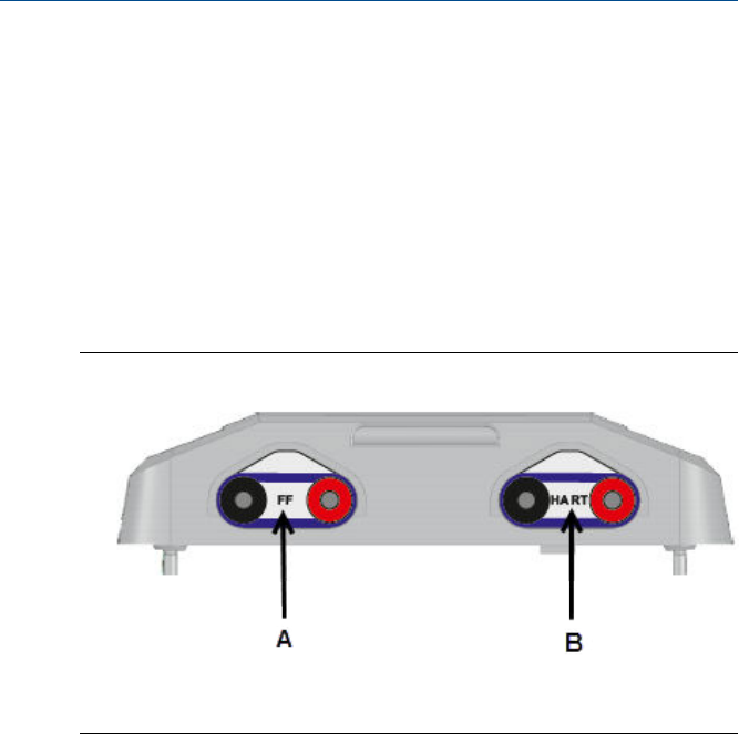
Device Communicator communication module
The Device Communicator communication module can connect to and
communicate with HART and FOUNDATION fieldbus devices on an
externally-powered HART loop or fieldbus segment. The Device
Communicator communication module has unique terminals for both HART
and FOUNDATION fieldbus devices.
Device Communicator communication moduleFigure 1-2:
A. Connect to externally-powered FOUNDATION fieldbus devices.
B. Connect to externally-powered HART devices.
Device Communicator Plus communication module
The Device Communicator Plus communication module can connect to
HART and FOUNDATION fieldbus devices, measure current and voltage, and
power a device.
Quick Start Guide June 2016
6Quick Start Guide
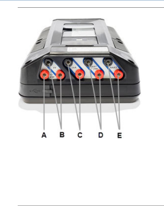
Device Communicator Plus communication moduleFigure 1-3:
A. Power a FOUNDATION fieldbus device. You need to connect the FOUNDATION
fieldbus Power Plug to the FF pwr and the positive FF terminals.
B. Connect to a FOUNDATION fieldbus device that is externally-powered or
powered by the Trex unit.
C. Measure current on a 4-20 mA current loop.
D. Power and connect to a HART device. The HART+pwr terminals can measure
current output of a connected transmitter or control the current input to a
connected positioner.
E. Connect to an externally-powered HART device. The HART terminals also have
an optional loop resistor for enabling HART communications on 4-20 current
loop and optional current control for moving a positioner.
Precautions
•Before you insert or remove a communication module, ensure the Trex
unit is powered off.
•Ensure sufficient grounding. Ensure the personnel, working surfaces, and
packaging are sufficiently grounded when handling electrostatically
sensitive parts.
June 2016 Quick Start Guide
Quick Start Guide 7
•Avoid touching the pins on the connectors or components. Discharged
energy can affect the modules.
•When you insert/attach the communication module to the Trex unit, do
not over tighten the screws. Use 0.5Nm maximum torque load.
CAUTION!
Remove the USB cable from the Trex unit before connecting to a device.
WARNING!
•The Trex unit cannot power a 4-wire device. Do not connect Trex unit to
the power terminals of a 4-wire device. This can blow a fuse inside the
Trex unit. The repair/replacement will need to be completed at an
authorized service center.
•Do not connect lead sets to the HART and HART + pwr terminals at the
same time. If the lead sets are connected to devices, this increases the
chance of wiring mistakes and could create a short in the HART loop.
•Do not add any external power to the device when the Trex unit is
powering the device. This can blow a fuse inside the Trex unit. The repair/
replacement will need to be completed at an authorized service center.
Ensure the device is disconnected from the loop/segment and no other
wires are connected to the device before providing power from the Trex
unit.
•Do not use the Trex unit to power a WirelessHART device. Providing
power to a WirelessHART device may damage the device.
•Do not connect the mA terminals (ammeter) in parallel with a powered
4-20 mA current loop. Ammeters have low resistance. This can disrupt
the loop and cause devices to report incorrect values or positioners to
move unexpectedly.
•Do not connect the mA terminals on the Trex unit to a power supply that
is not current limited to 250 mA. This can blow a fuse inside the Trex unit.
The repair/replacement will need to be completed at an authorized
service center.
Power on or off
1. To power on, press and hold the power button on the upper left side of
the Trex unit for one second.
2. To power off, do one of the following:
•Quickly press the power button, and then tap Turn Off.
Quick Start Guide June 2016
8Quick Start Guide

•Tap Settings or the status bar at the top of the screen, and tap More >
Power Management > Turn off.
Device connections
Use the provided lead set and the Field Communicator application to
communicate with a device. The appropriate device description is also
required. If the Trex unit does not have the HART device description revision,
the device is displayed in generic mode. This mode does not display all device
functionality. If the Trex unit does not have the fieldbus device description,
the device cannot be configured.
See the wiring diagrams in the Trex Device Communicator User Guide for more
information.
CAUTION!
The Trex unit draws approximately 12 mA from the fieldbus segment when it
is online. (The Trex unit draws 0 mA when it is offline.) Ensure the power
supply or barrier on the fieldbus segment has the capacity to provide this
additional current when the Trex unit is online. If a heavily loaded fieldbus
segment is drawing near the capacity of the segment’s power supply,
connecting the Trex unit may result in loss of communication.
Maintenance and repair
Any maintenance, repair, or replacement of components not listed below
must be performed by specially trained personnel at an authorized service
center. You can perform common maintenance procedures listed below:
•Clean the exterior. Use only a dry, lint-free towel or dampen the towel
with an alcohol or mild soap and water solution.
•Clean the touchscreen.
•Charge, install, or remove the power module.
•Remove and replace the stand.
•Ensure that all exterior screws are sufficiently tightened.
•Ensure the communication terminal recess is free of dirt and debris.
•Install and remove the communication module.
Technical support
Contact your local representative or go to the Trex Device Communicator
website for technical support contact information.
June 2016 Quick Start Guide
Quick Start Guide 9
2 Product certifications
See the Trex Device Communicator website for the latest certificates,
declaration of conformity, and approval information.
Approved manufacturing location
R. STAHL HMI Systems GmbH - Cologne, Germany
Labels
Each Trex unit has a main unit label. An Intrinsically Safe (KL option) Trex unit
has another label on the side. If the Trex unit does not have this label, it is
considered non-IS approved.
Certifications and approvals
European directive information - CE compliance
ATEX
(2014/34/EU)
This equipment complies with the ATEX Directive. Applicable standards are
EN 60079-0:2012 + A11:2013, EN 60079-11:2012, and EN 60079-26:2007.
Certification No.:
II 2 G (1GD) Ex ia [ia Ga] [ia Da IIC] IIC T4 Gb (-10°C < Ta < +50°C)
0158
Electro Magnetic
Compatibility
(EMC)
2014/30/EU
Tested to the EN 61326-1:2006 and ETSI EN 301489-17:2002-08
specification.
Low Voltage Tested to the EN 61010-1:2001 + Corrigendum / Errata specification.
International certifications
IECEx Certification No.:
Ex ia [ia Ga] [ia Da IIC] IIC T4 (Tambient = 50°C)
North American certifications
Canadian
Standards
Association (CSA)
Intrinsically Safe for use in Class I, Ex ia [ia Ga] [ia Da IIC] IIC T4 (-10°C < Ta <
+50°C) hazardous locations when connected as indicated in the control
drawing.
Quick Start Guide June 2016
10 Quick Start Guide
Wireless/Spectrum approvals
FCC This equipment has been tested and found to comply with the limits for a Class A
digital device, pursuant to part 15 of the FCC Rules. These limits are designed to
provide reasonable protection against harmful interference when the equipment
is operated in a commercial environment. This equipment generates, uses, and
can radiate radio frequency energy and, if not installed and used in accordance
with the user’s manual, may cause harmful interference to radio communications.
Operation of this equipment in a residential area is likely to cause harmful
interference in which case the user will be required to correct the interference at
his own expense.
This device complies with Part 15 of the FCC Rules. Operation is subject to the
following two conditions: (1) this device may not cause harmful interference, and
(2) this device must accept any interference received, including interference that
may cause undesired operation.
Any modifications made to this device that are not approved by Emerson Process
Management may void the authority granted to the user by the FCC to operate
this equipment.
IC This Class A digital apparatus complies with Canadian ICES-003.
Cet appareil numérique de la classe A est conforme à la norme NMB-003 du
Canada.
RED
(2014/53/
EU)
This equipment is in conformity with the Radio Equipment Directive (RED)
Directive, ETSI EN 300328: 2012-06, and IEC 62209-2:2007 standards.
WEEE
Label Description
Products with this label comply with the Waste Electrical and Electronic Equipment
(WEEE) directive, 2012/19/EU, which applies to European Union (EU) member
states only.
The label indicates this product should be recycled and not treated as household
waste. Customers in EU member states should contact their local Emerson sales
representative for information on discarding any part of the product.
For customers in all other world areas, if it is necessary to discard any part of the
product, follow the waste-disposal regulations applicable in your location.
RoHS Label Description
RoHS
Pb
Products with this label are lead-free and comply with the Restriction of the Use
of Certain Hazardous Substances in Electrical and Electronic Equipment (RoHS)
directive, 2011/65/EU, which applies to EU member states only. The EN 50581:
2012 is the applicable standard.
The purpose of the directive is to limit the use of lead, cadmium, mercury,
hexavalent chromium, polybrominated biphenyl (PBB), and polybrominated
diphenyl ether (PBDE) flame retardants in electronic equipment.
Hazardous areas
A Trex unit that meets the Intrinsic Safety requirements (IS-approved) can be
used in Zone 1, or Zone 2, for Group IIC, and Class I, Division 1 and Division 2,
Groups A, B, C, and D locations.
June 2016 Quick Start Guide
Quick Start Guide 11
An IS-approved Trex unit may be connected to loops or segments that are
attached to equipment located in Zone 0, Zone 1, Zone 2, for Group IIC; Zone
20, Zone 21, Zone 22, and Class I, Division 1 and Division 2, Groups A, B, C,
and D locations.
An IS-approved Trex unit can be ordered with the KL option. The Trex unit has
a label that lists the approvals.
Note
Do not use a screen protector on an IS-approved Trex unit.
WARNING!
You cannot install, remove, or charge the Lithium Ion (Li-Ion) power module
in a hazardous area environment.
WARNING!
Explosions can result in serious injury or death.
Use in an explosive environment must be in accordance with the appropriate
local, national, and international standards, codes, and practices. Please
review the Technical specifications and Product certifications sections of the
Trex Device Communicator User Guide for any restrictions associated with safe
use.
Electrical shock can result in serious injury or death.
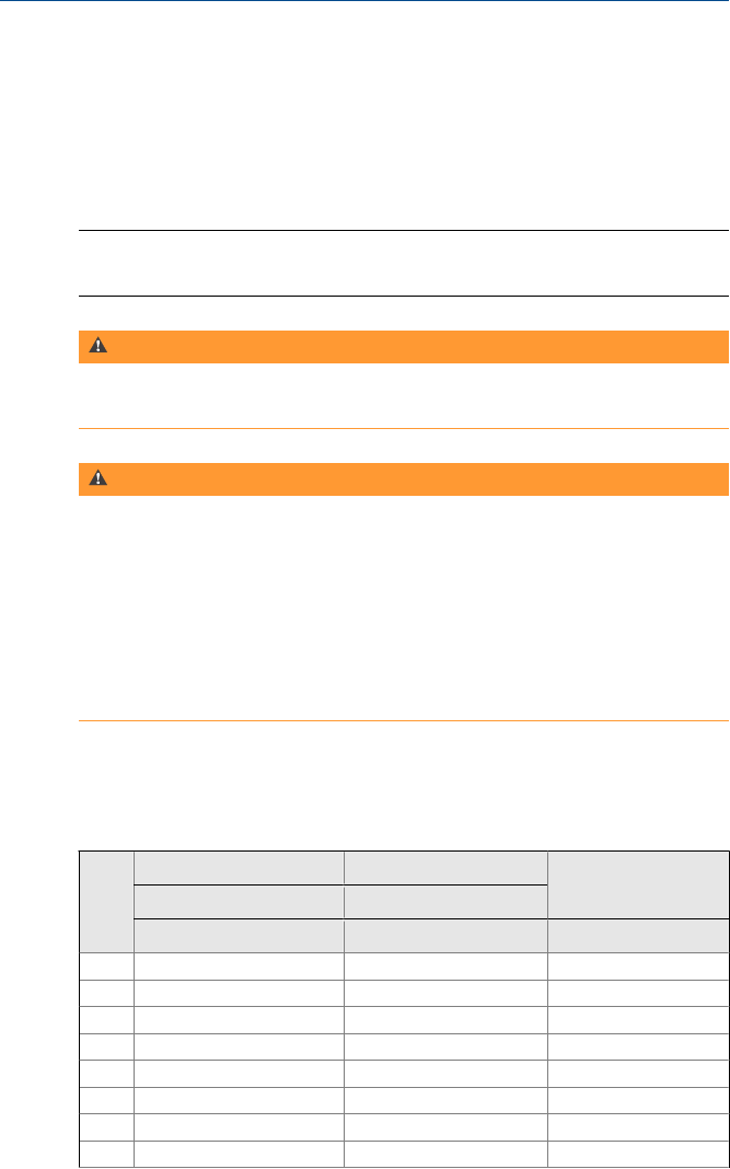
Intrinsically Safe electrical parameters
Device Communicator communication module
FOUNDATION™ fieldbus FOUNDATION™ fieldbus
HART®
(non-FISCO) (FISCO)
FF + and - FF + and - HART + and -
Ui 30 Vdc 30 Vdc 30 Vdc
Ii 380 mA 215 mA (IIC) 380 mA (IIB) 200 mA
Pi 1.3 W 1.9 W (IIC) 5.3 W (IIB) 1.0 W
Ci 0 0 0
Li 0 0 0
Uo 1.89 V 1.89 V 1.89 V
Io 32° µA 32° µA 32° µA
Po 61 µW 61 µW 61 µW
Quick Start Guide June 2016
12 Quick Start Guide

FOUNDATION™ fieldbus FOUNDATION™ fieldbus
HART®
(non-FISCO) (FISCO)
FF + and - FF + and - HART + and -
Co 14.3 µF 14.3 µF 14.3 µF
Lo 100 mH 100 mH 100 mH
Device Communicator Plus communication module
mA
interface
FOUNDATION™
fieldbus
HART®
FOUNDATION™ fieldbus
(non-FISCO) (FISCO)
mA
FF pwr
and F- FF + and -
HART +
pwr
HART +
and -
FF pwr
and F - FF + and -
Ui 30 Vdc 17.5 Vdc 30 Vdc 30 Vdc 30 Vdc 17.5 Vdc 30 Vdc
Ii 200 mA 380 mA 380 mA 200 mA 200 mA 380 mA 215 mA (IIC)
380 mA (IIB)
Pi 1.0 W 1.3 W 1.3 W 1.0 W 1.0 W 1.3 W 1.9 W (IIC)
5.3 W (IIB)
Ci 0 231 nF 0 0 0 231 nF 0
Li 0 0 0 0 0 0 0
U
o0 17.31 V 1.89 V 25.69 1.89 V 17.31V 1.89 V
Io 0 199 mA 32° µA 105 mA 1.9 mA 199 mA 32° µA
P
o0 0.94 W 61 µW 668 mW 3.6 mW 0.94 W 61 µW
C
o100 µF * nF 14.3 µF ** nF 14.3 µF * nF 14.3 µF
L
o100 mH * µH 100 mH ** mH 100 mH * µH 100 mH
* FF pwr and F -
Co [nf] 19 69 115
Lo [µF] 100 50 30
** HART + pwr
Co [nf] 57 64 75 102
Lo [µF] 1000 750 500 100
June 2016 Quick Start Guide
Quick Start Guide 13

AC adapter specifications
Electrical Specification
AC input voltage range 90-264 VAC
Frequency 47 - 63Hz
Input current 1.6A max. at low line input and full load output
Inrush current 60 A max. at 230VAC input and 25°C ambient temperature
Leakage current <0.25 mA
Input protection 1.6A 250VAC Fuse
No load power consumption <0.5W max. at nominal input and no load output
Output voltage 15 V
Output current 4.33 A
Ripple and noise 1% Vout
Hold up time 10ms at nominal input and full load output
No load operation Yes, to protect power supply and system from damage
Short circuit protection Auto recovery, cannot exceed 8A max. after 1 minute at
nominal input line.
Over current protection 150-200%, foldback type, auto recovery
Over voltage protection 110-140%, voltage limiting, recycle input to recover
Operating temperature range 0°C to + 50°C
Operating humidity 8-90% RH non-condensing
Operating altitude Maximum of 2000 meters
Storage temperature range -20°C to +70°C
Storage humidity 5-95% RH non-condensing
Cooling Free air convection
Dimensions 119 x 54x 36mm
Weight 0.33 kg
Withstand voltage I/P-O/P (FG): 3kVAC / 10 mA / 1 minute
EMI EN55022: 2006 Class B, EN61000-3-2:2006, EN61000-3-3:
1995+A1: 2001+A2:2005 EN55024:1998+A1: 2001+A2:
2003, IEC61000-4-2, -3, -4, -5, -6+A1:2004, -8, -11
Safety CB (IEC60950-1: 2001), TUV GS (EN60950-1: 2005 +A1 +
A2), cUL, CE, VCCI
Approvals
cUL North America, TUV GS Europe, Japan PSE, IRAM Argentina, Russian EAC,
Kazakhstan EAC, South Africa SANS IEC 60 950, Korean EK, China CCC.
WEEE 2012/19/EU, RoHS (2011/65/EU)
Quick Start Guide June 2016
14 Quick Start Guide

Quick Start Guide
TREX-0045-0001_Draft_6716
June 2016
Emerson Process Management
12001 Technology Drive
Eden Prairie, MN 55344 USA
T 1(952)828-3032
F 1(952)828-3033
www.EmersonProcess.com
©2016, Emerson Process Management
The contents of this publication are presented for
informational purposes only, and while every effort
has been made to ensure their accuracy, they are
not to be construed as warranties or guarantees,
express or implied, regarding the products or
services described herein or their use or
applicability. All sales are governed by our terms
and conditions, which are available on request. We
reserve the right to modify or improve the designs
or specifications of our products at any time
without notice.
All rights reserved. The Emerson logo is a
trademark and service mark of Emerson Electric Co.
All other marks are property of their respective
owners.