R tron APEX1933 Industrial Booster User Manual Rev 6
R-tron Inc. Industrial Booster Users Manual Rev 6
UserManual.wiki
>
R tron
>
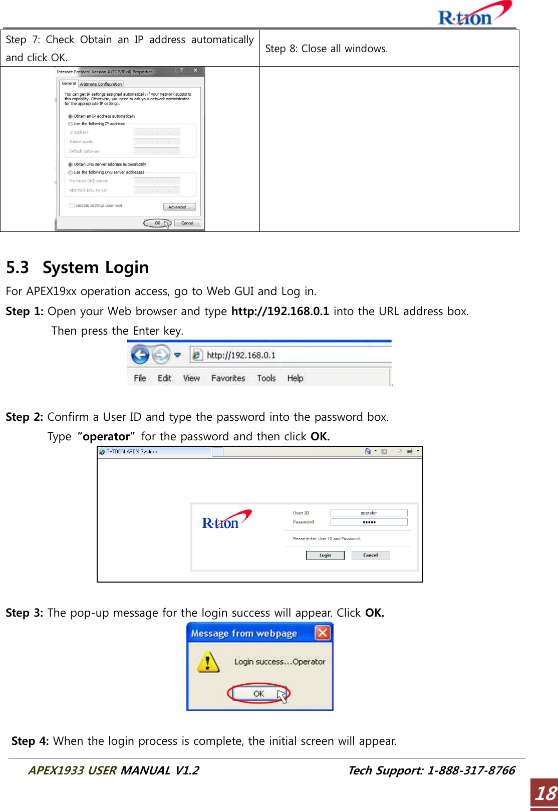
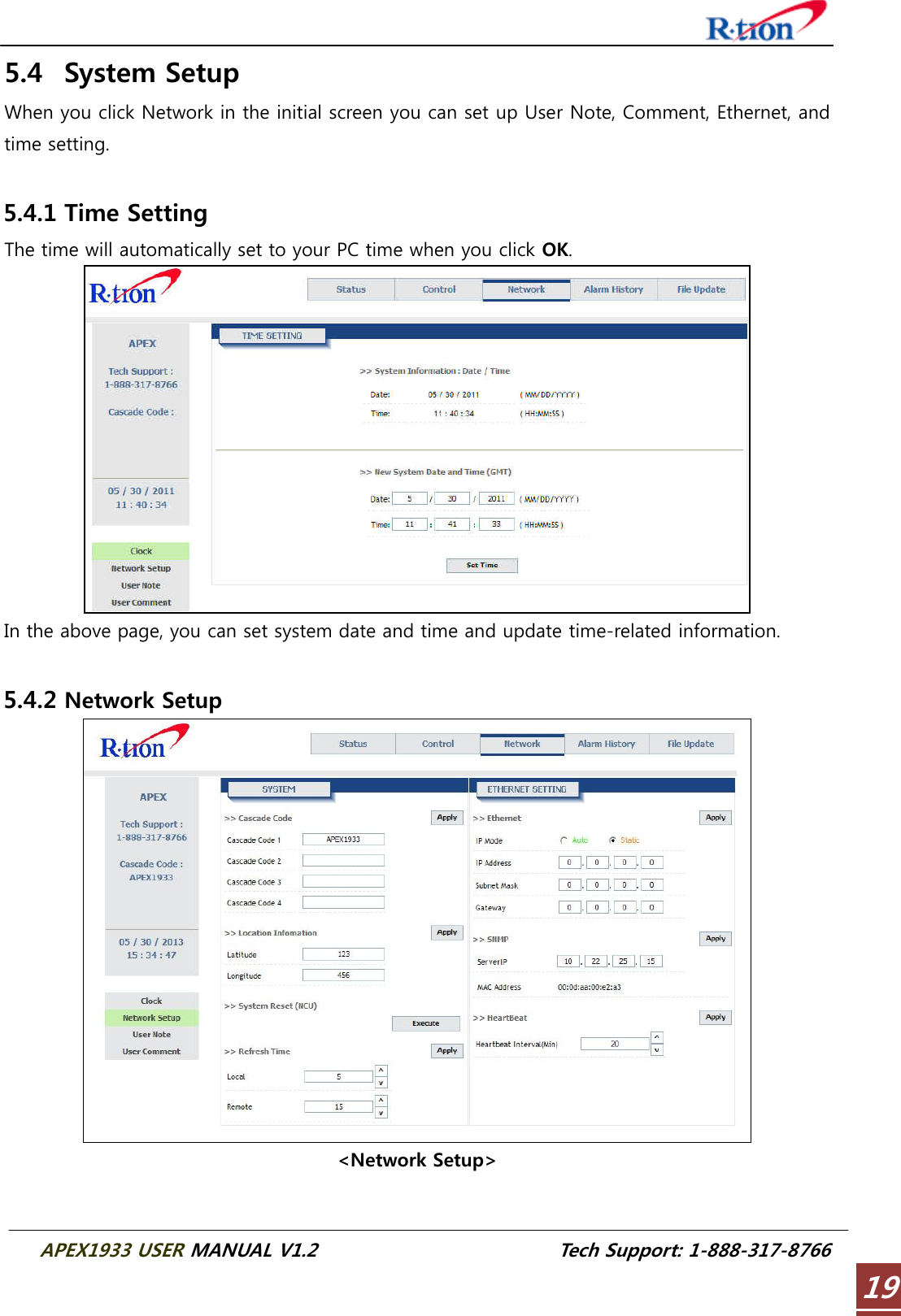
APEX1933 User Manual
Users Manual Rev 6
Navigation menu
Upload a User Manual
Namespaces
Wiki Guide
HTML
PDF
Info
Views
User Manual
Discussion / Help
Navigation
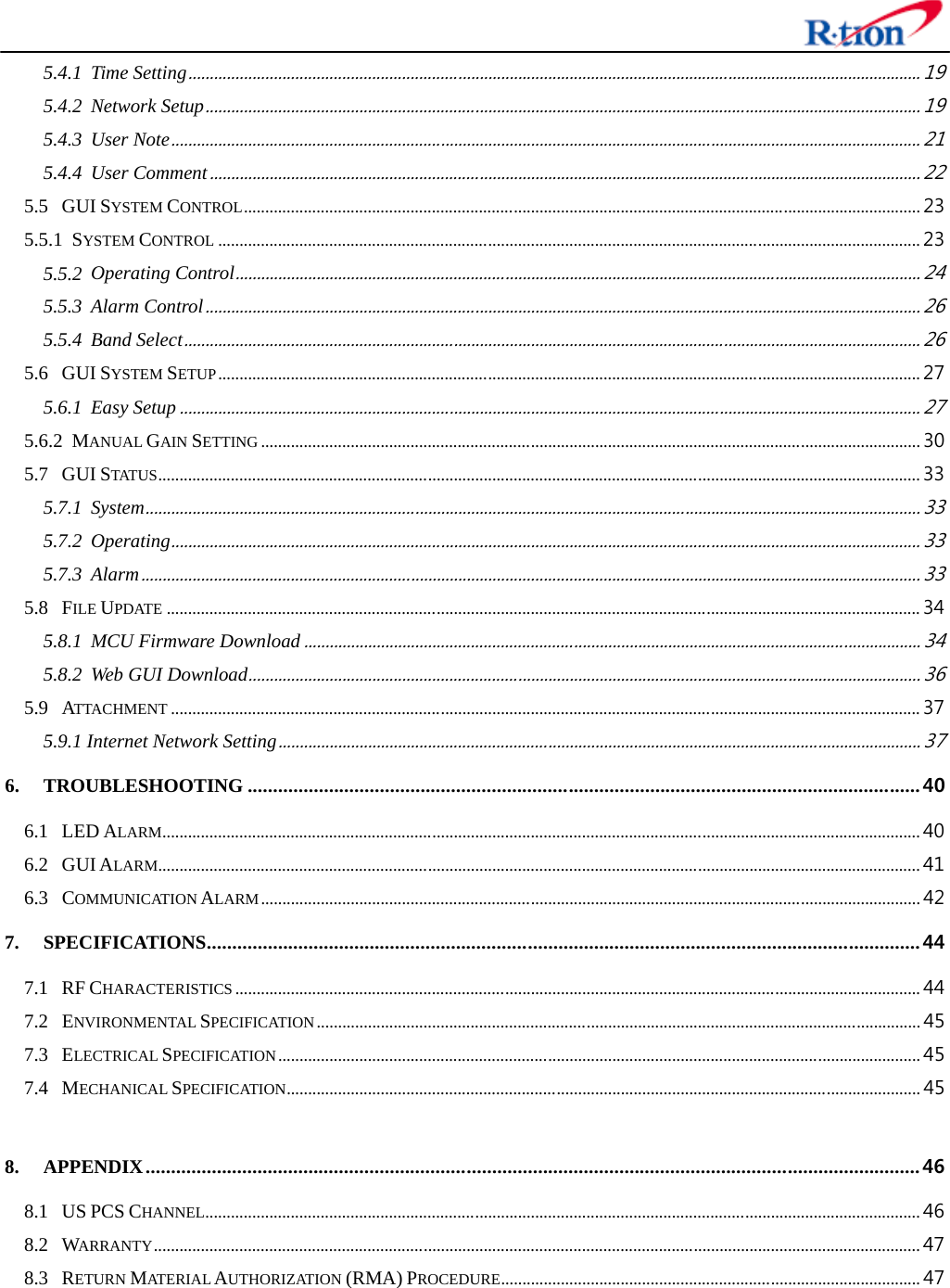


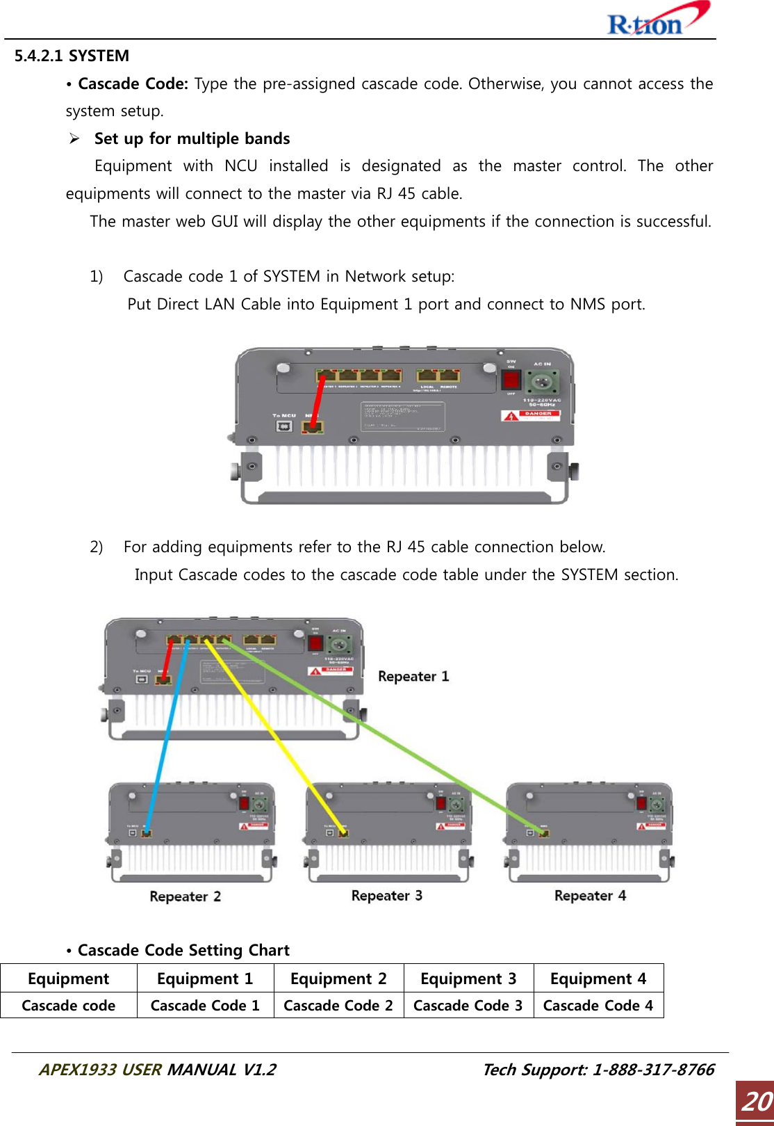
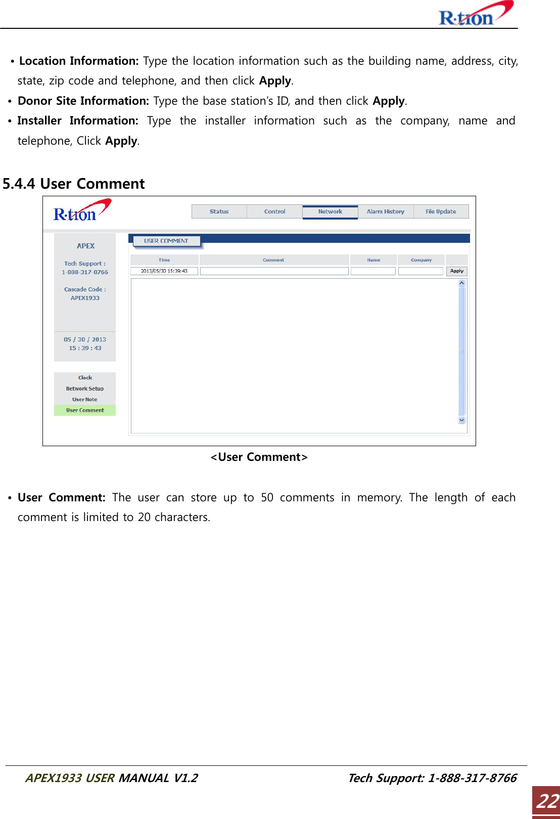
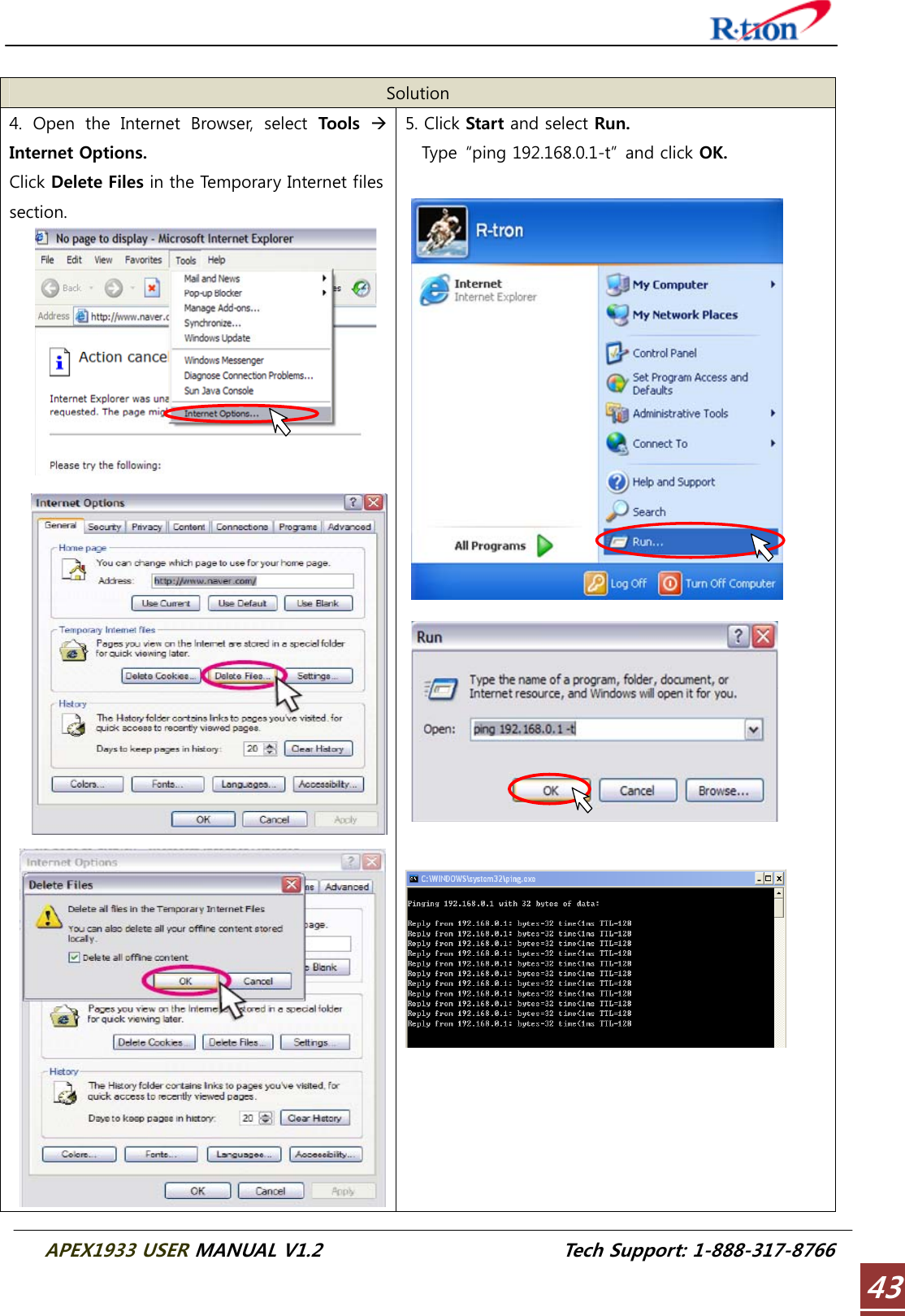
![APEX1933 USER MANUAL V1.2 Tech Support: 1-888-317-8766 21• Location Information: Enter the latitude and longitude. You can input values either in Decimal Degrees or Degrees-Minutes-Seconds. [Example] (‘N/S’ | ‘E/W’) ddd.dddddd: (Latitude: N 39.006967 Longitude: W 94.532306) • Refresh Time: Set each refresh time for connecting to Local port and Remote port. 5.4.2.2 ETHERNET SETTING • Ethernet IP Mode/IP Address: Enables you to set a connection mode for the network connected to the APEX19xx remote LAN port. When you “select” Auto, the device automatically assigns the IP address. When you select “Static”, it is possible to set an IP address of your choosing. • SNMP: In order to send Heartbeat and alarm related information to a remote monitoring server, you can set a server IP address. The factory default IP address is 10.22.25.15. • Heartbeat Interval: Sets the time to transmit the Heartbeat to the NMC Server. (Default value is 20 minutes.) 5.4.3 User Note <User Note>](https://usermanual.wiki/R-tron/APEX1933/User-Guide-2213799-Page-25.png)