R tron QUADCOMM-700N LTE Repeater User Manual
R-tron Inc. LTE Repeater Users Manual
UserManual.wiki
>
R tron
>
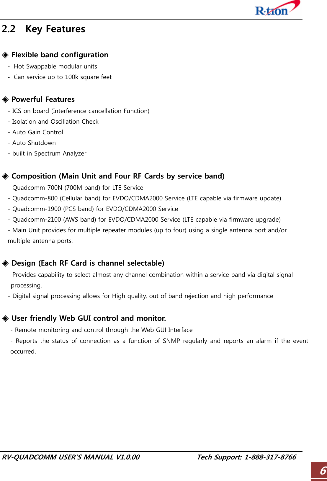
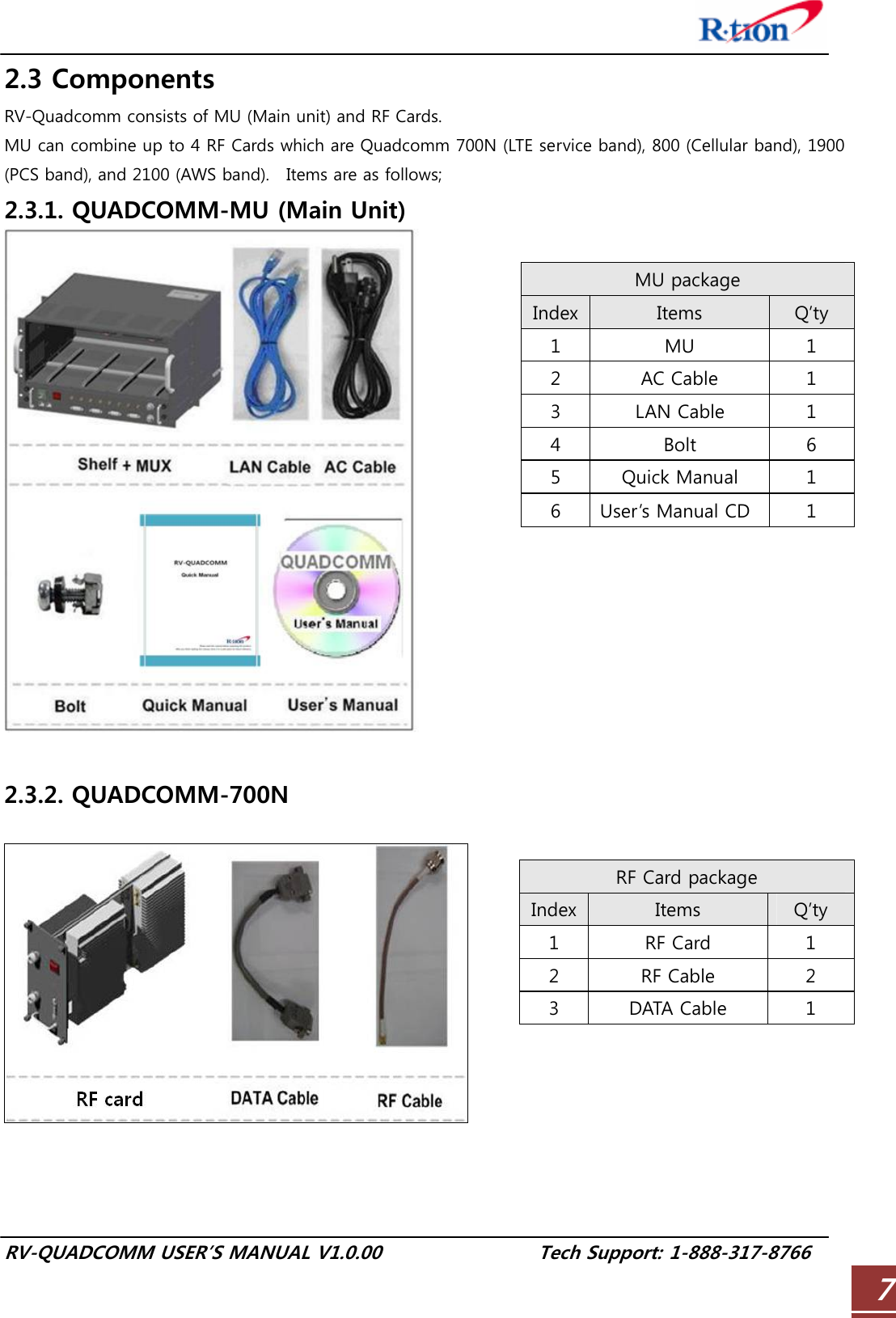
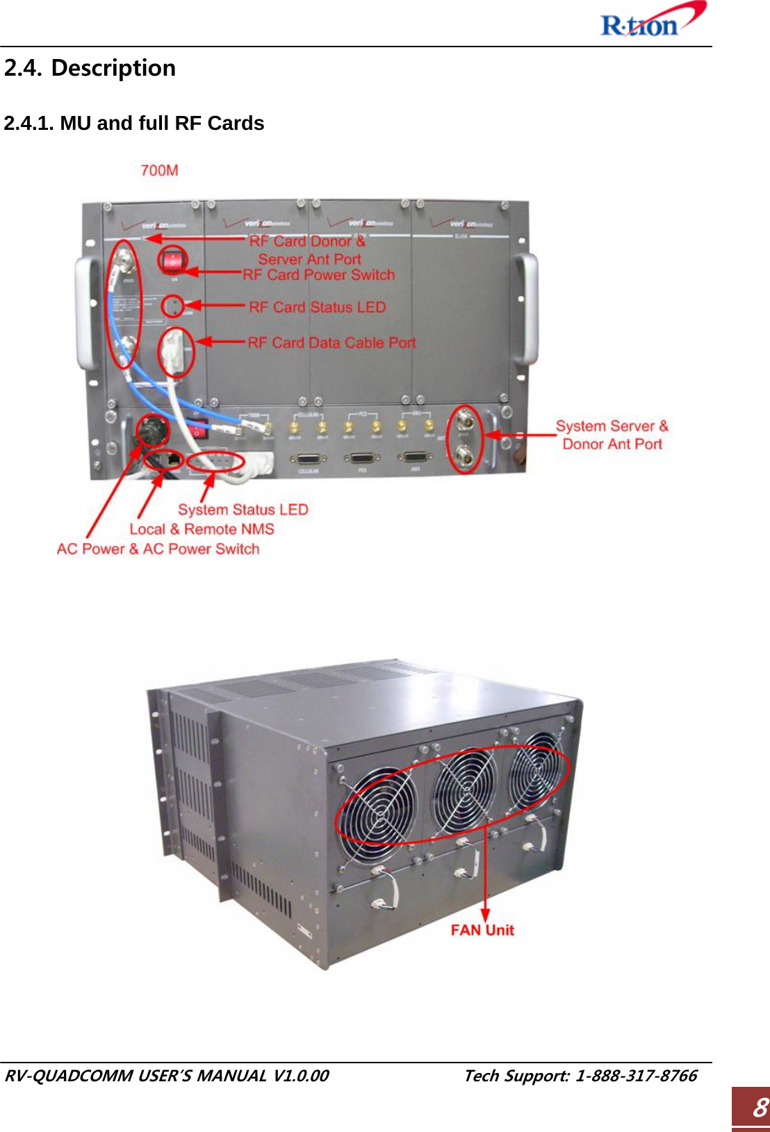
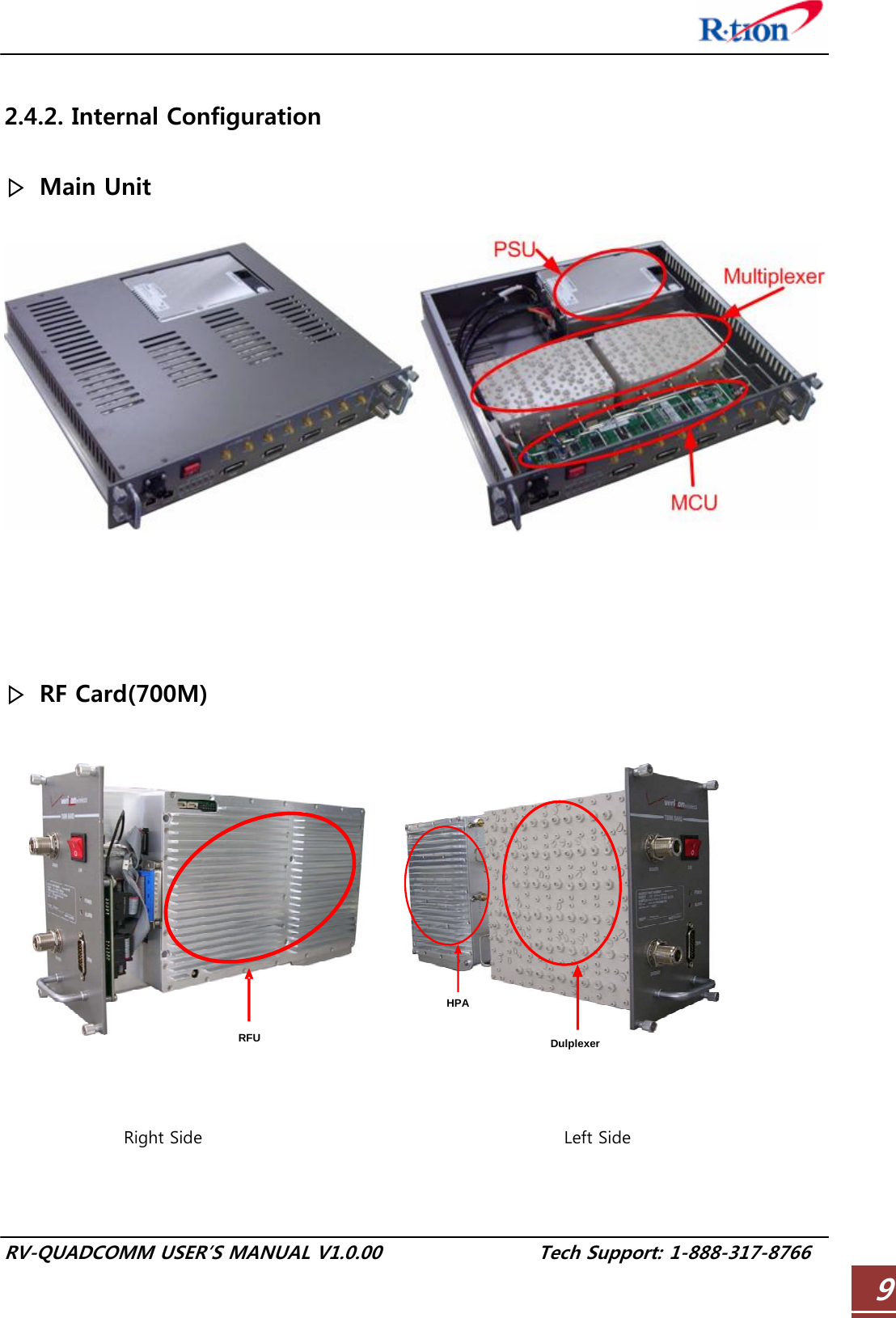
QUADCOMM 700N User Manual
Users Manual
Navigation menu
Upload a User Manual
Namespaces
Wiki Guide
HTML
PDF
Info
Views
User Manual
Discussion / Help
Navigation
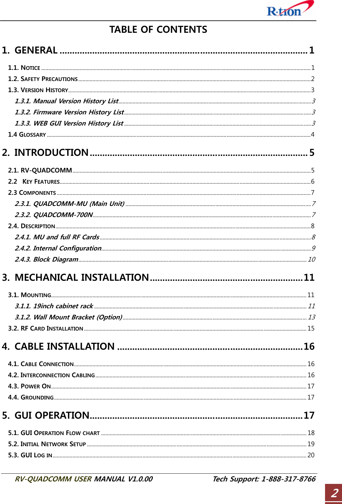
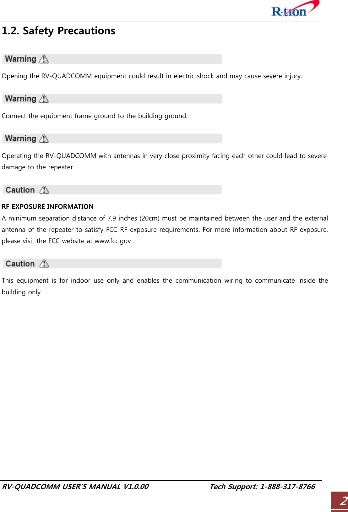
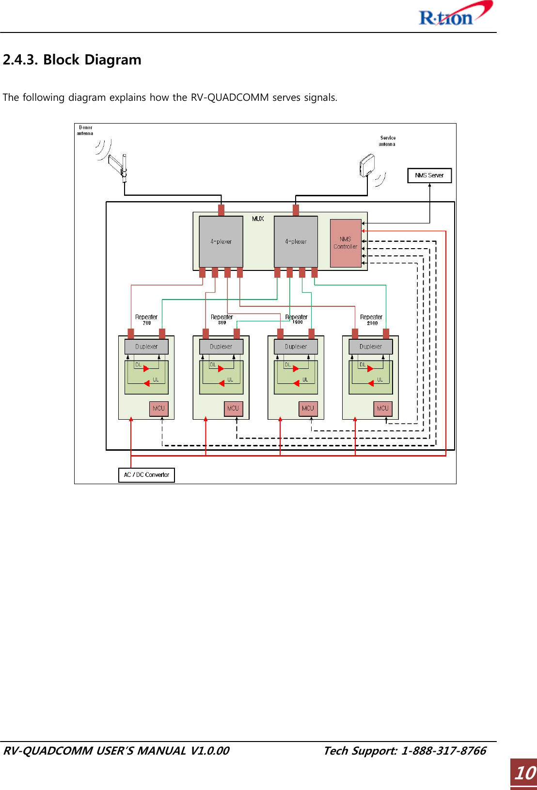
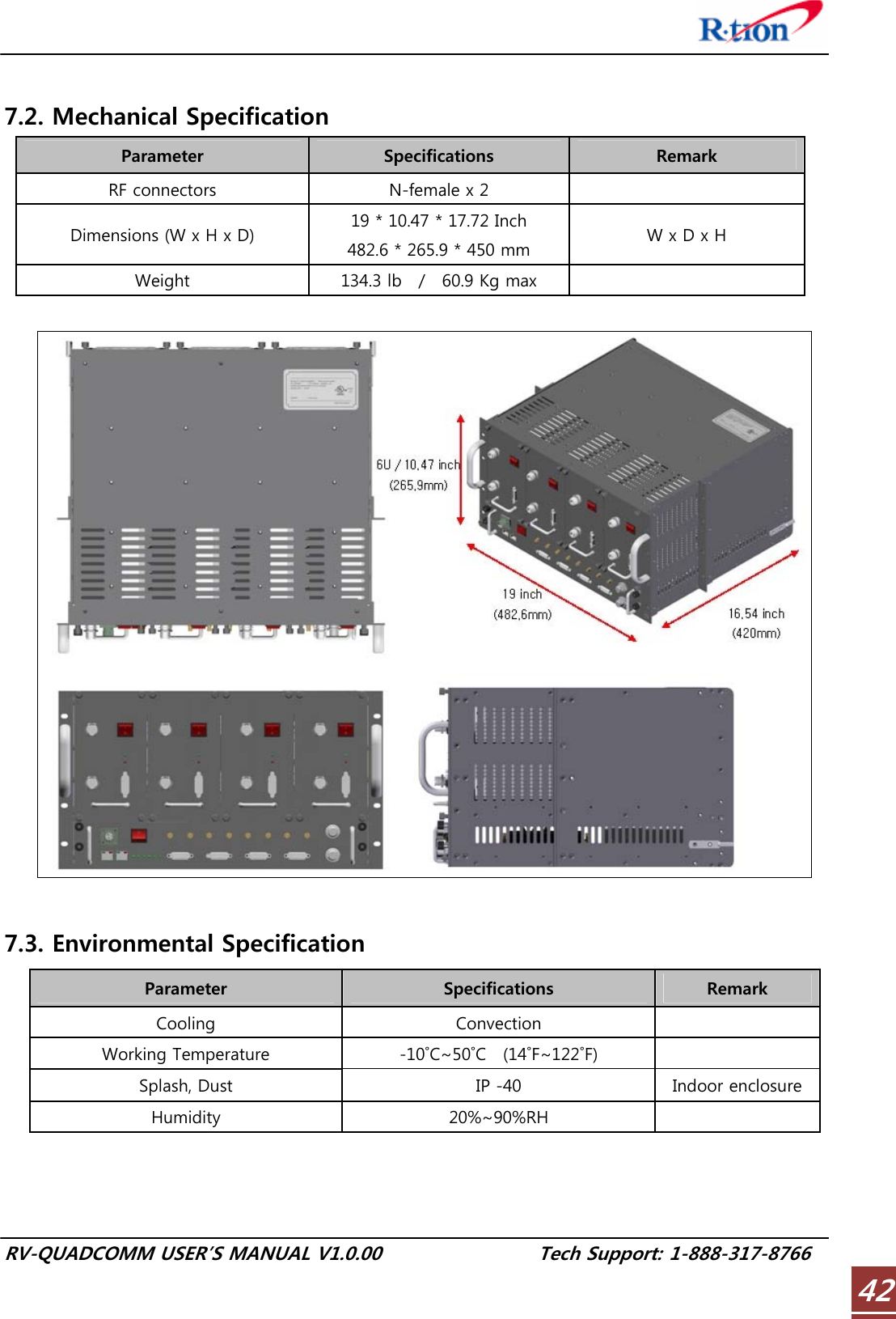
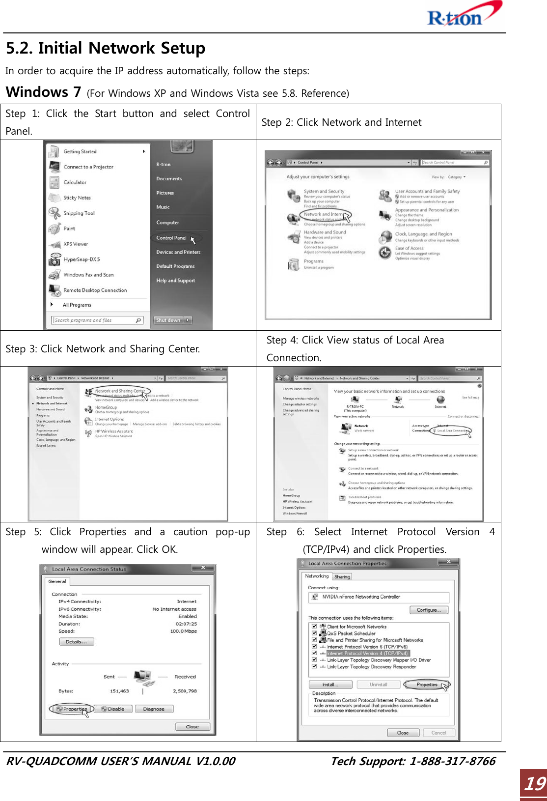
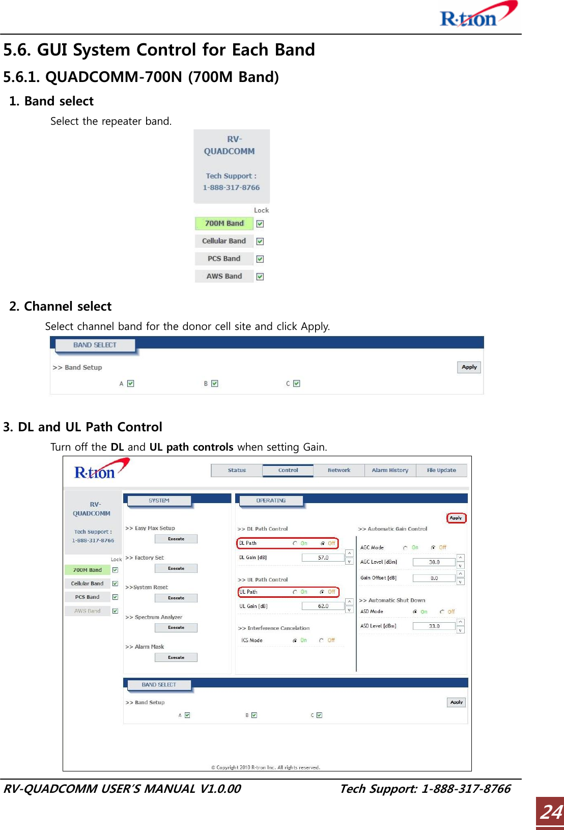
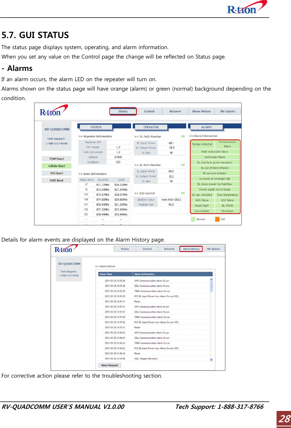
![RV-QUADCOMM USER’S MANUAL V1.0.00 Tech Support: 1-888-317-8766 185.1. GUI Operation Flow chart 1. Time Setting Automatically set to your PC time. 2. System Information Input Input Cascade Code and Location Information. 3. Ethernet Setting IP address and SNMP IP Input. 1. Lock Select Only checked bands will report to the server. 2. Band Select Click the band for Web GUI control. 3. Channel Select Select channel band [5] GUI Status CheckYou can see system, operating, and alarm information on Status page. 4.A. AGC control AGC automatically assigns gain. 4.B. Manual Control Gain value setting by User. Setting in order to acquire the IP address automatically. The user can control the repeater locally using the built-in WEB GUI. RV-Quadcomm Web GUI Log in. [1] Internet Network Setup System will be set automatically without manual operation.4.C. Easy Max Setup [3] GUI Network Setup[4] GUI System Control [2] GUI Log-in](https://usermanual.wiki/R-tron/QUADCOMM-700N/User-Guide-1564684-Page-21.png)
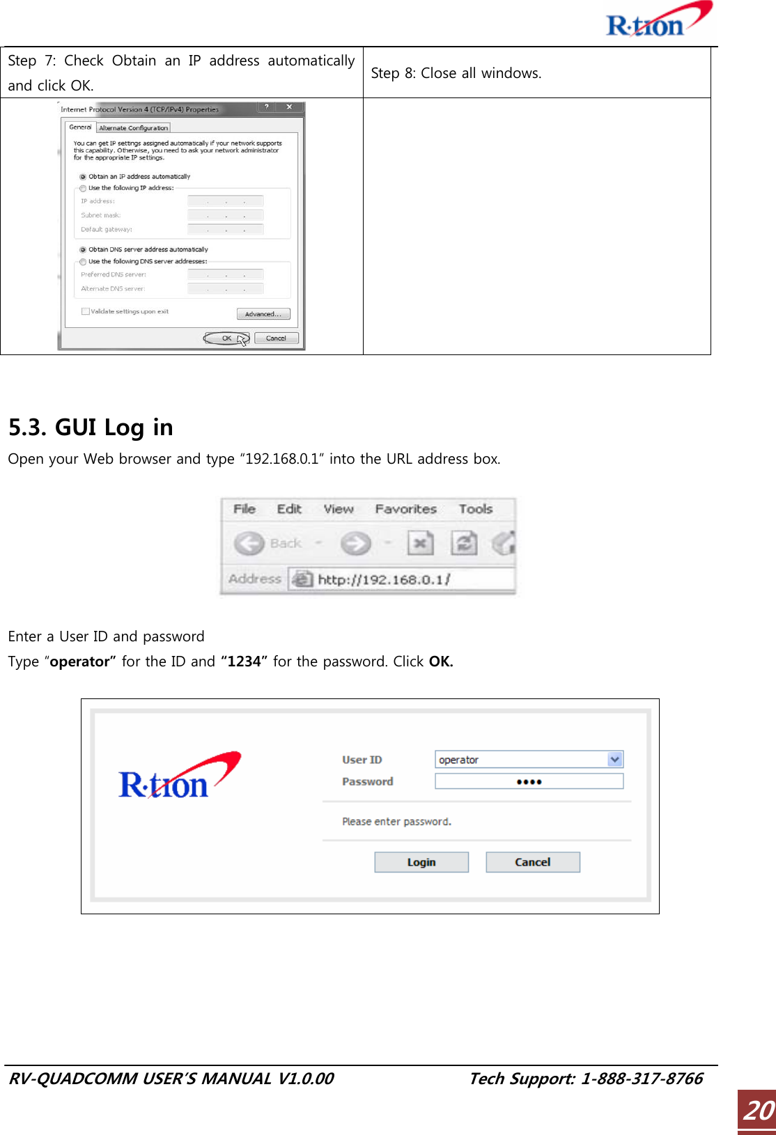
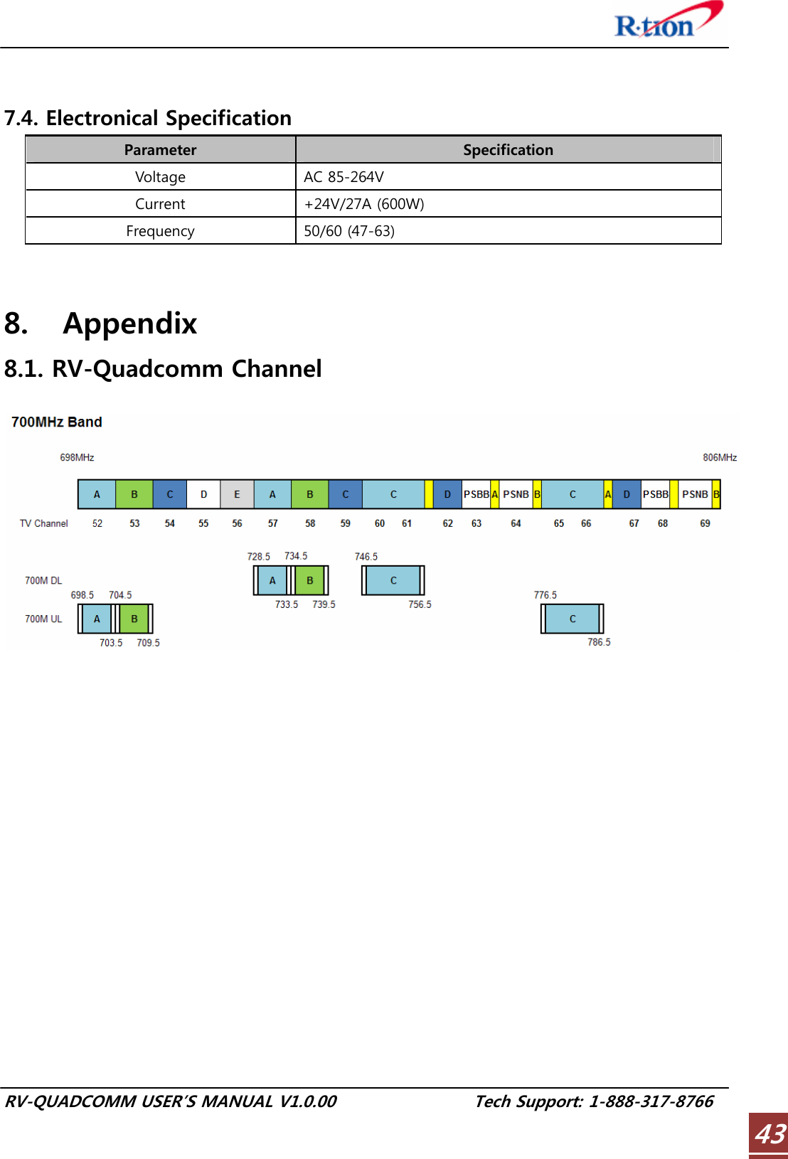
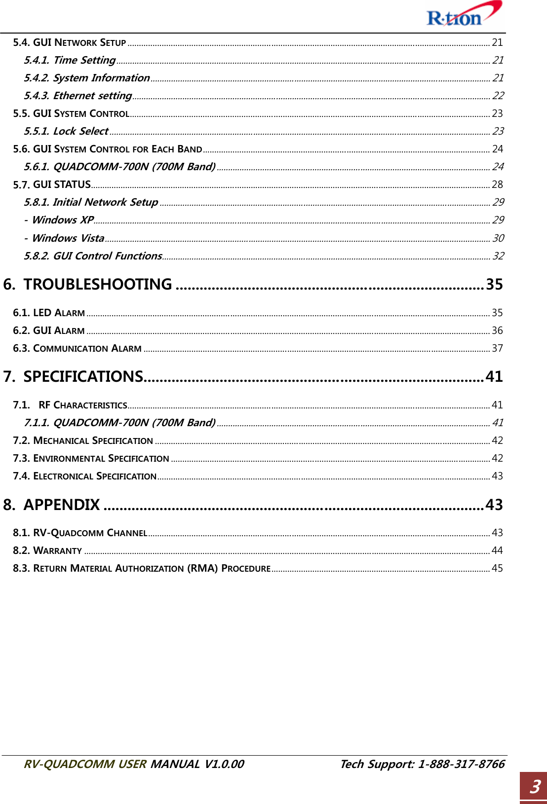
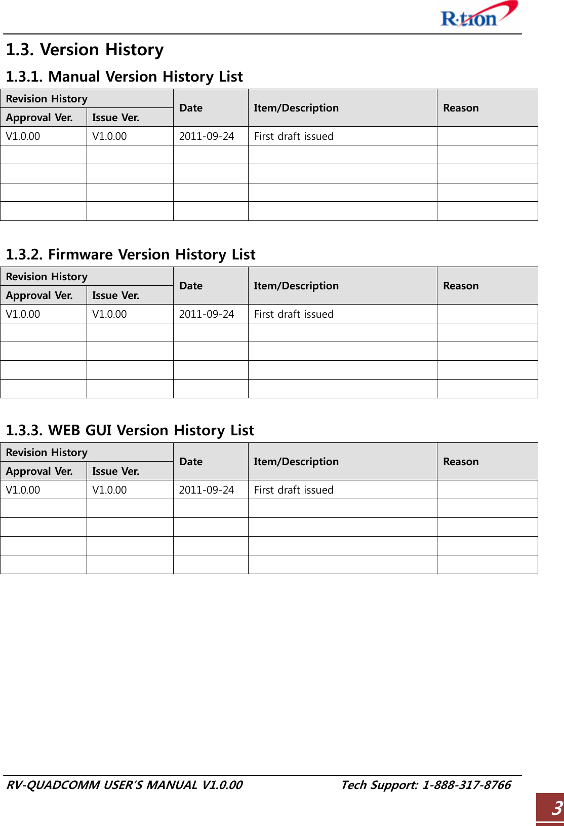
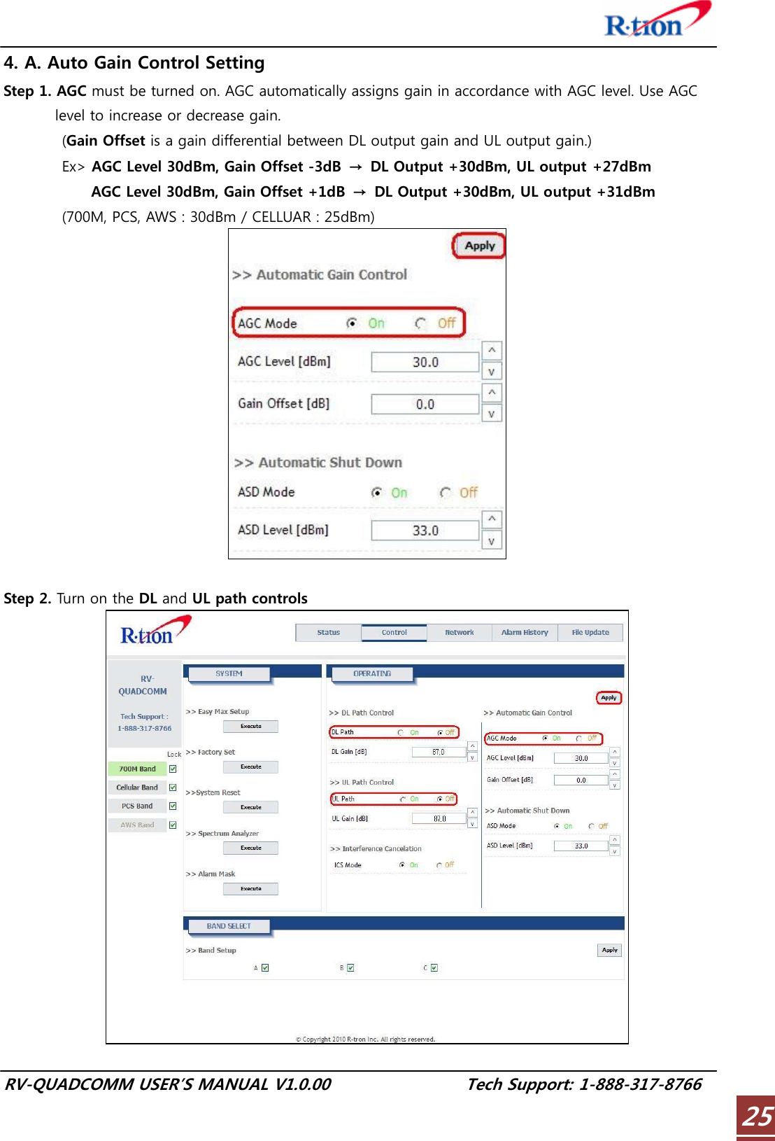
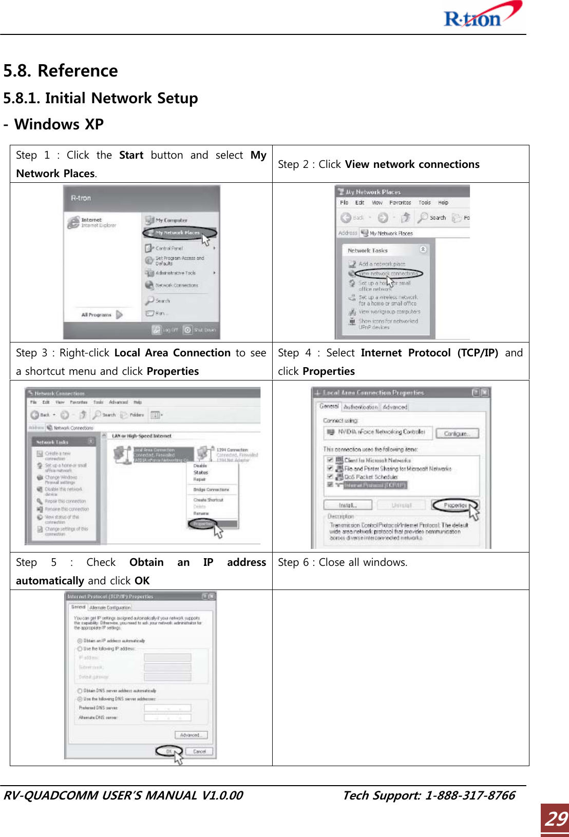
![RV-QUADCOMM USER’S MANUAL V1.0.00 Tech Support: 1-888-317-8766 215.4. GUI Network Setup The network page allows you to set up system information, configure Ethernet perimeters, and set time. 5.4.1. Time Setting The time will automatically set to your PC time when you click the Set Time. 5.4.2. System Information Cascade Code: Type the pre-assigned code. Location Information: Enter the latitude and longitude of the location otherwise you cannot access the system setup. You can input values either in Decimal Degrees or Degrees-Minutes-Seconds. [Example] (‘N/S’ | ’E/W’) ddd.dddddd: (Latitude: N 39.006957 Longitude: W 94.532306)](https://usermanual.wiki/R-tron/QUADCOMM-700N/User-Guide-1564684-Page-24.png)
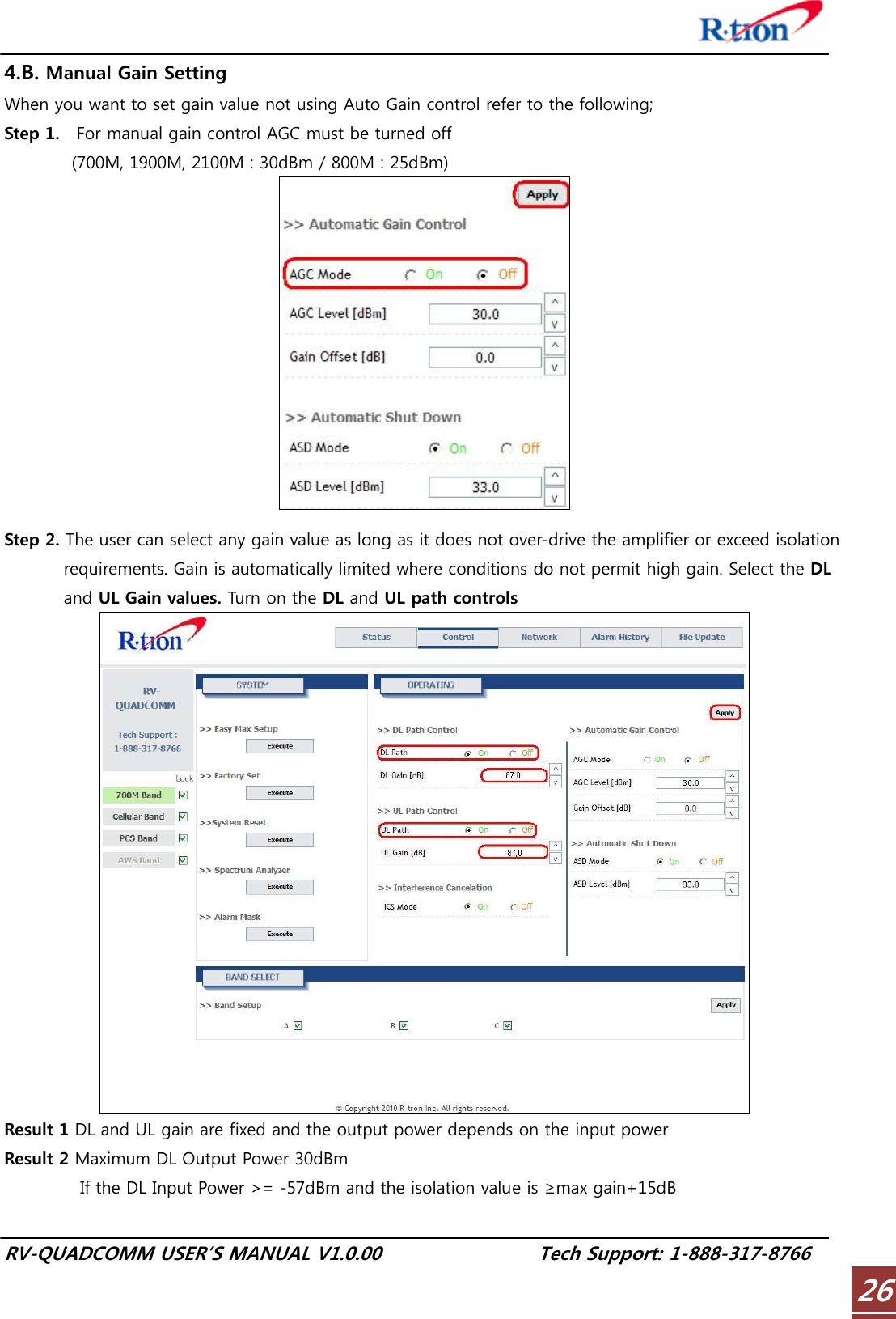
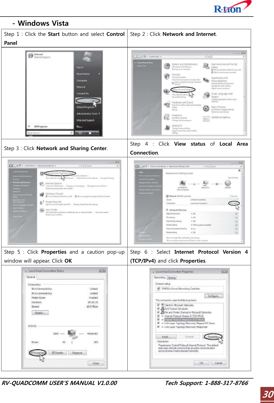
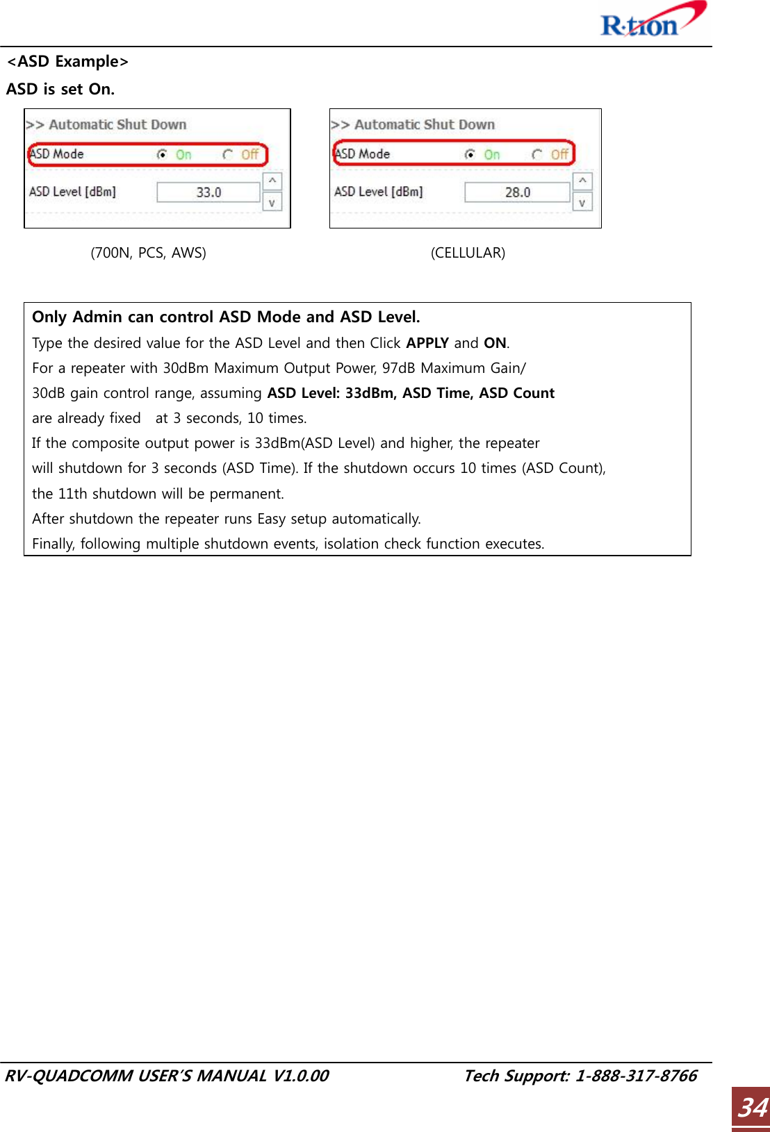
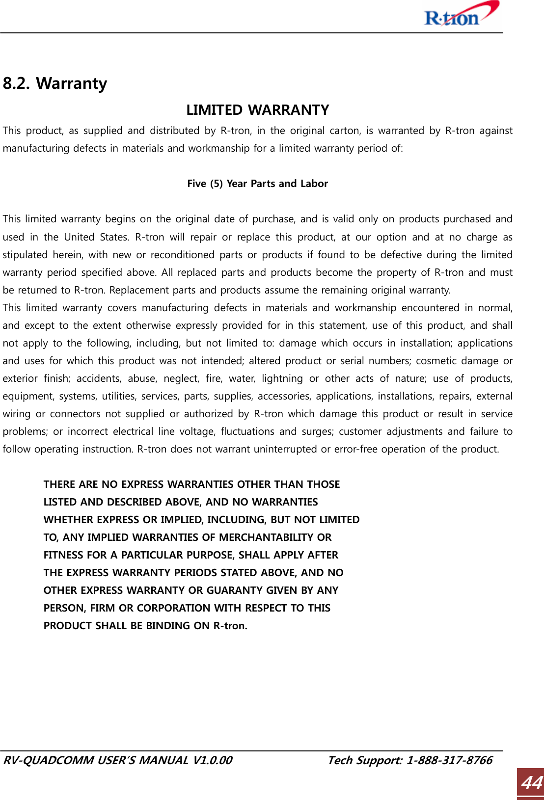
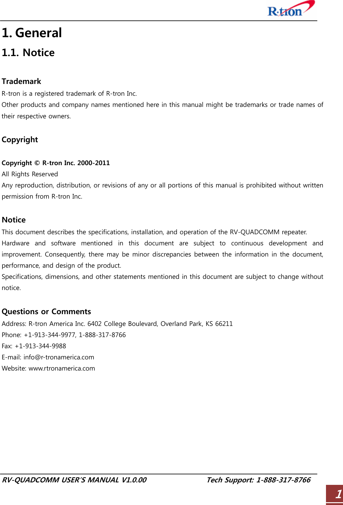
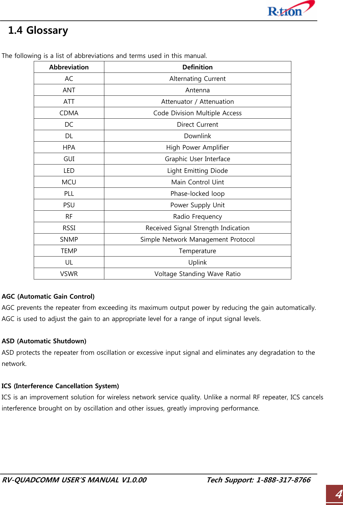
![RV-QUADCOMM USER’S MANUAL V1.0.00 Tech Support: 1-888-317-8766 335.8.2.2. AGC and ASD Function AGC (Automatic Gain Control) : AGC feature prevents the repeater from exceeding its maximum output power by reducing the gain automatically. AGC is used to adjust the gain to an appropriate level for a range of input signal levels. ASD (Automatic Shut Down ) : ASD protects the repeater from oscillation or excessive input signal and eliminates any degradation to the network. There are three parameters: ASD Level, ASD Time, and ASD Iteration. If the output power reaches higher than the “ASD LEVEL”, the repeater will shut down for “ASD TIME” seconds and then turn the amp back on to measure output power. If shut down repeats “Iteration” times, the repeater will shut down permanently. <AGC Example> [applied at the Quadcomm-800] Select AGC On and enter a value equal to or less than 30dBm, click APPLY and ON. For a repeater with 25dBm maximum output power, 90dB maximum gain/25dB gain Control range, Æ If the input signal is -65dBm and AGC level is 15dBm, the gain will be 80dB. * To apply this for each Band refer to Automatic Gain Control Setting following section of 5.6.](https://usermanual.wiki/R-tron/QUADCOMM-700N/User-Guide-1564684-Page-36.png)