R tron RSP-DPP-1900 HB1900 User Manual Revision 2
R-tron Inc. HB1900 Users Manual Revision 2
R tron >
Users Manual Revision 2

R-TRON Proprietary & Confidential Page 1
HB 1900
(Heartbeat 1900)
User’s Manual

R-TRON Proprietary & Confidential Page 2
Copyright
Copyright of this manual belongs to R-tron America, Inc.
Reproduction, distribution or revision of part or all of contents in this manual in any form without
written permission of R-tron America, Inc. is not permitted
Registered Trademark
R-tron is registered trademarks of R-tron America, Inc
Other products and company names mentioned herein this manual might be trade marks
or trade names of their respective owners.
HB 1900
Copyright © 2004 R-TRON, Inc. All Rights Reserved
Copyright © 2005 R-tron America, Inc. All Rights Reserved
The results of using information not mentioned in this manual or the risk of
misunderstanding this document remain with the user.
The information in this manual is subject to change due to function enhancement,
change of design, etc. If you want the modified manual or have any question on this
manual, please contact us at:
R-tron America, Inc Address : 10977 Granada Lane, Suite #225
Overland Park, KS 66212
Tel : +1-913-593-5205

R-TRON Proprietary & Confidential Page 3
Revision History
Version Date of revision Reason for revision Revision Description
V1.0 Sep.21.2005 The First Edition
V1.1 Oct.05.2005 Second Edition
RF EXPOSURE INFORMATION
The antenna used for this transmitter must not exceed 2.5dBi and must be installed to
provide a minimum separation distance of 20cm from all persons.
R-TRON Proprietary & Confidential Page 4
1. Overview
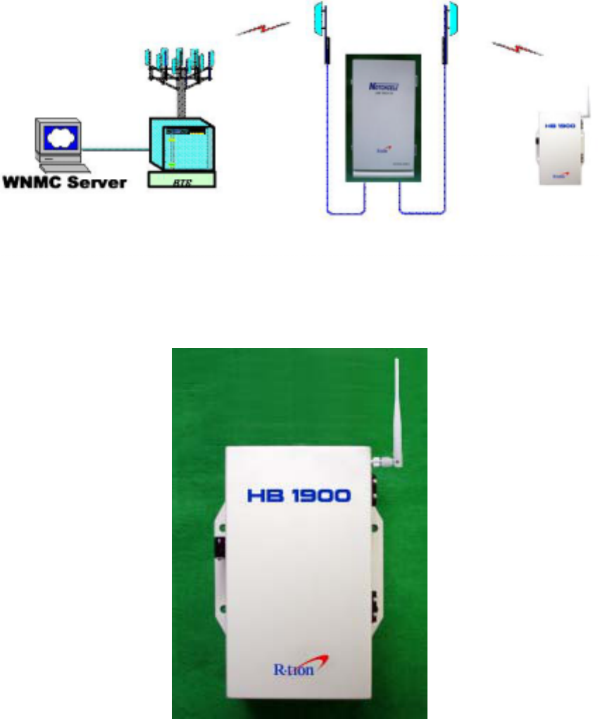
HB(Heart Beat)1900 is designed for the purpose of checking the repeater systems which were
installed in Sprint network.
Using CDMA 1x modem protocol, heartbeat is happened only when the repeater system
operates correctly. It traces the repeater status and give heartbeat signal periodically to WNMC
server through SNMP Trap.
<Heartbeat transfer Configurations>
2. HB 1900 Description
R-TRON Proprietary & Confidential Page 5
2.1 HB 1900 Specification
2.1.1 Environmental conditions
Item Standard Remark
Power supply 85V~264V, 50/60Hz typ.
Operating temperature - 20 ~ +50℃
Storage temperature - 30 ~ +60℃
Humidity 95 %
Consumption power 15W
Table 1. Environmental Specification of HB 1900
2.1.2 System Specification
Item Specifications Remark
Down Link 1930 ~ 1990MHz Frequency
range Up Link 1850 ~ 1910 MHz
Heartbeat interval 3~59 min
Interface Connector RS-232C
VSWR ≤1.5
Atten Range 1~30dB 1dB Step
Atten Control Accuracy ±1.5dB
Dimension(W*D*H) 170*300*74 Unit : mm
Weight 2.4kg
Table 2. features Specification of HB 1900
2.2 HB 1900 Block Diagram
R-TRON Proprietary & Confidential Page 6
3. SUB Unit description & Specification
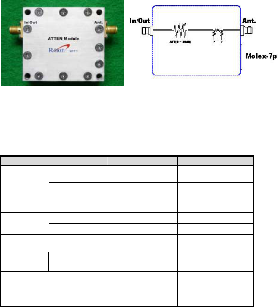
3.1 Attenuation Module
<Figure 1 Attenuation Module> <Figure 2 Block diagram>
Attenuation Module function is sending signal to modem which is properly leveled and it sends
Signal to repeater wirelessly, controlling modem output level.
* Specification *
Item Specifications Remark
Down Link 1930~1990 MHz
Up Link 1850~1910 MHz
Frequency
range Ant <-> In/Out
Insertion Loss -15dB ± 1dB
Frequency range
(1850 MHz ~1990 MHz)
@ ATT 0dB
Ant Port -10dBm
Max
Input Power In/Out Port 20dBm(100mW)
ATT Range 30dB / 1dB Step Active Low
VSWR - S11,S22 1 : 1.3 Min
Ant Port SMA Female Type
RF
Connector In/Out Port SMA Female Type
Interface Connector Molex 5264-7p
Operating Temp. -30℃ ~ +60℃
Operating Voltage DC 5V ± 0.5V
Dimension(W*D*H) 60*90*30 Unit : mm
Table 3. Specification of Atten Module
R-TRON Proprietary & Confidential Page 7
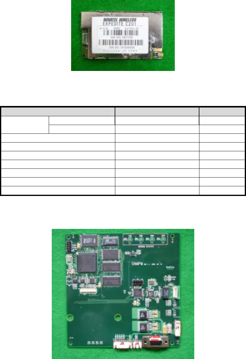
3.2 Wireless Modem (Expedite C201)
<Figure 3 Wireless Modem>
Wireless Modem (Expedite C201) is designed for WNMC interconnection function
* Specification *
Item Specifications Remark
Down Link 1930 ~ 1990MHz Frequency
range Up Link 1850 ~ 1910 MHz
Storage Temperature -30℃ to + 85℃
Operating Temperature -20℃ to +60℃
RF Channel Bandwidth 1.25MHz
Frequency Accuracy ±150Hz
Operating Voltage 3.45V to 4.20V
Maximum Output Power 100mW (20.0dBm)
Dinamic Range -104dBm ~ -64dBm
3.3 SNMP Board
<Figure 4 SNMP Board>
R-TRON Proprietary & Confidential Page 8
The SNMP Board located in the HB 1900 cabinet which is the essential of the HB 1900.
The SNMP board contains powerful microprocessors.
Operational parameters, such as Heartbeat interval, Modem Attenuation, SNMP version, Site ID,
etc. are set using a desktop or notebook and OMT, which communicate, locally via RS-232C
cable, with the RRMS. Remote operation is performed via CDMA net
* Connection *
Port Connected to
J1 SNMP Board Vcc
J4 Debugging port
J5 ATTEN Module Vcc & Control
D-SUB 9PIN Local OMT
* LED *
LED
TxD Display communication status between Modem &SNMP Board
RxD Display communication status between Modem &SNMP Board
OPR Turn on a light in Heartbeat Range
RDY Turn on a light when modem power is on
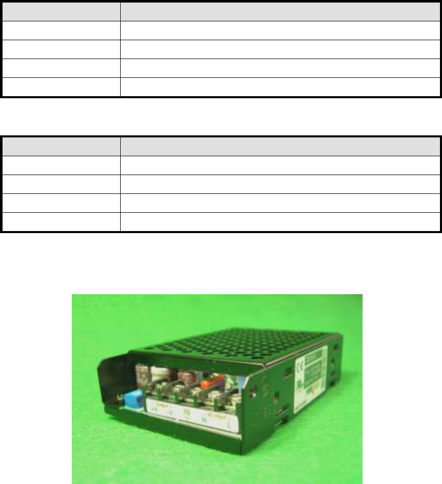
3.4 AC/DC Power Supply Unit
<Vendor 1>
<Figure 5 AC/DC Power Supply Unit >
PSU receives and converts input power (AC 110V) into DC +5V.
R-TRON Proprietary & Confidential Page 9
* Specification *
Item Specifications Remark
Operating Temp -10 ~60℃℃
Storage Temp -20 ~70℃℃
Humidity 20%~90%RH
Environmental
Cooling method Natural air
Voltage AC85~264V
Current 3A Max / 5Vdc
Frequency 47~440Hz max(50~60Hz typ)
Leakage Current 0.5mA max.@110V AC
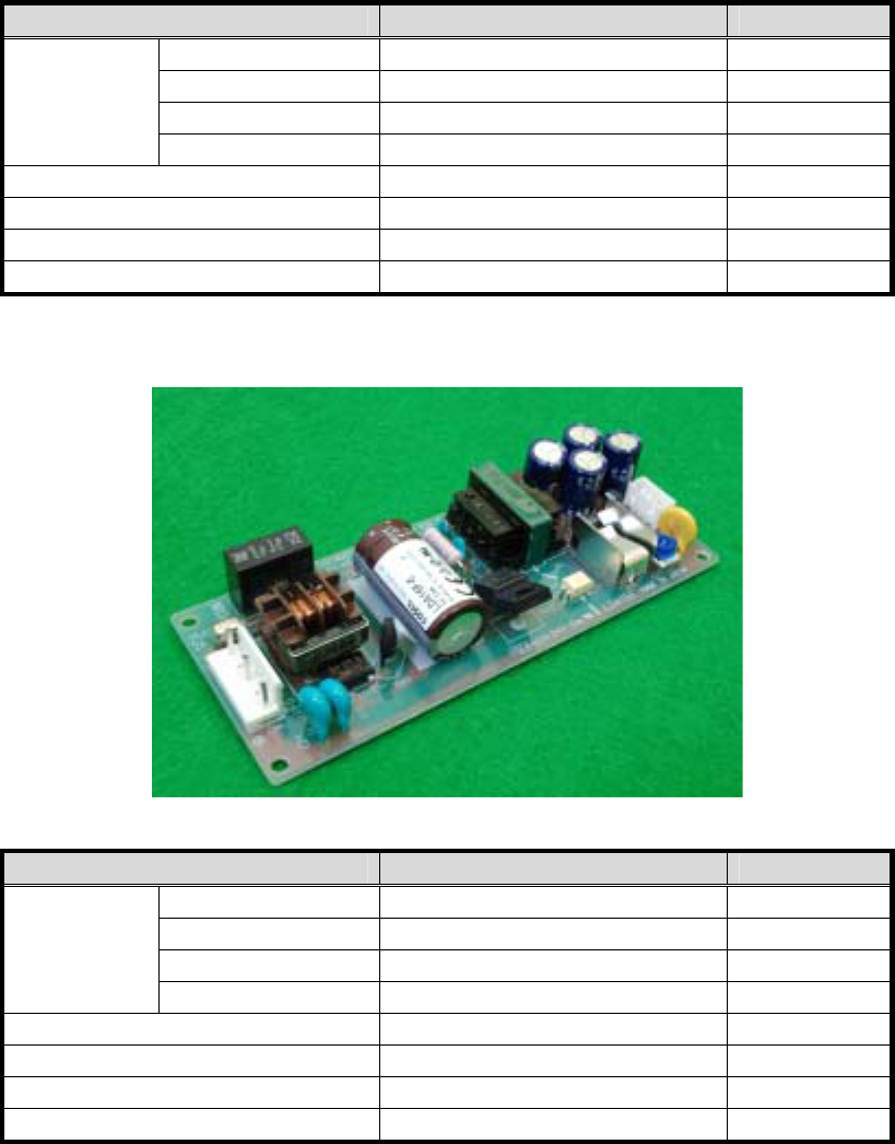
<Vendor2>
* Specification *
Item Specifications Remark
Operating Temp -10 ~60℃℃
Storage Temp -20 ~7℃5℃
Humidity 20%~90%RH
Environmental
Cooling method Natural air
Voltage AC85~264V
Current 3A Max / 5Vdc
Frequency 47~440Hz
Leakage Current 0.75mA max. 60Hz

R-TRON Proprietary & Confidential Page 10
3.5 Antenna
<Figure 6 Antenna >
* ELECTRICAL Specification *
Item Specifications Remark
Down Link 1930 ~ 1990MHz Frequency
range Up Link 1850 ~ 1910 MHz
Max input power 5W
VSWR Less than 1.5:1
Gain 2.0dBi±0.5
Radiation pattern Omni-directional
Polarization VERTICAL
Antenna Type Sleeve dipole
Impedance 50 Ω
* MECHANICAL SPECIFICATIONS *
Item Specifications Remark
Overall Length of Ant 166.5 ±2.0 mm
Weight 30 g
Temperature -30℃~+70℃
Cover material Urethane (HI 153-9082)
White COLOR
Connector Type SMA-Male
4. Installation
4.1 How to install Program File
GUI program consists of one exe file. Therefore, you can copy one exe file to your PC and use it.
R-TRON Proprietary & Confidential Page 11
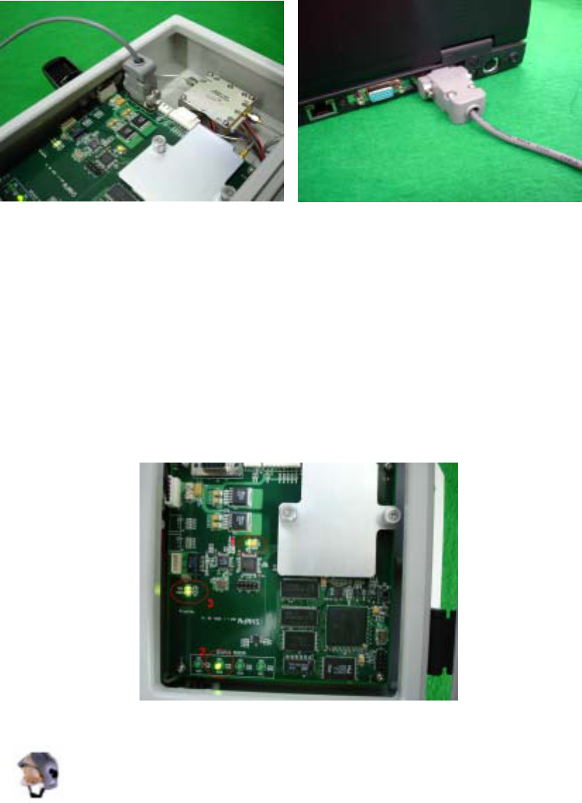
4.2 Connect communication cable
Connect communication cable as followings,
4.3 Power on
After connecting the communication cable, you can supply AC power to the HB 1900. As you
can see the following picture, when you supply AC power to the HB 1900, the DC 5V LED light
up one time. After 3 or 4 seconds later, the modem power(3.3Voltage) LED light up two times.
Then 10 seconds later, the LED light three times. This signals that the heartbeat unit is ready for
communication. Finally, you can execute GUI program and get the heartbeat communication
started.
4.4 How to start GUI Program
Click HB 1900 v1_2.exe.
R-TRON Proprietary & Confidential Page 12
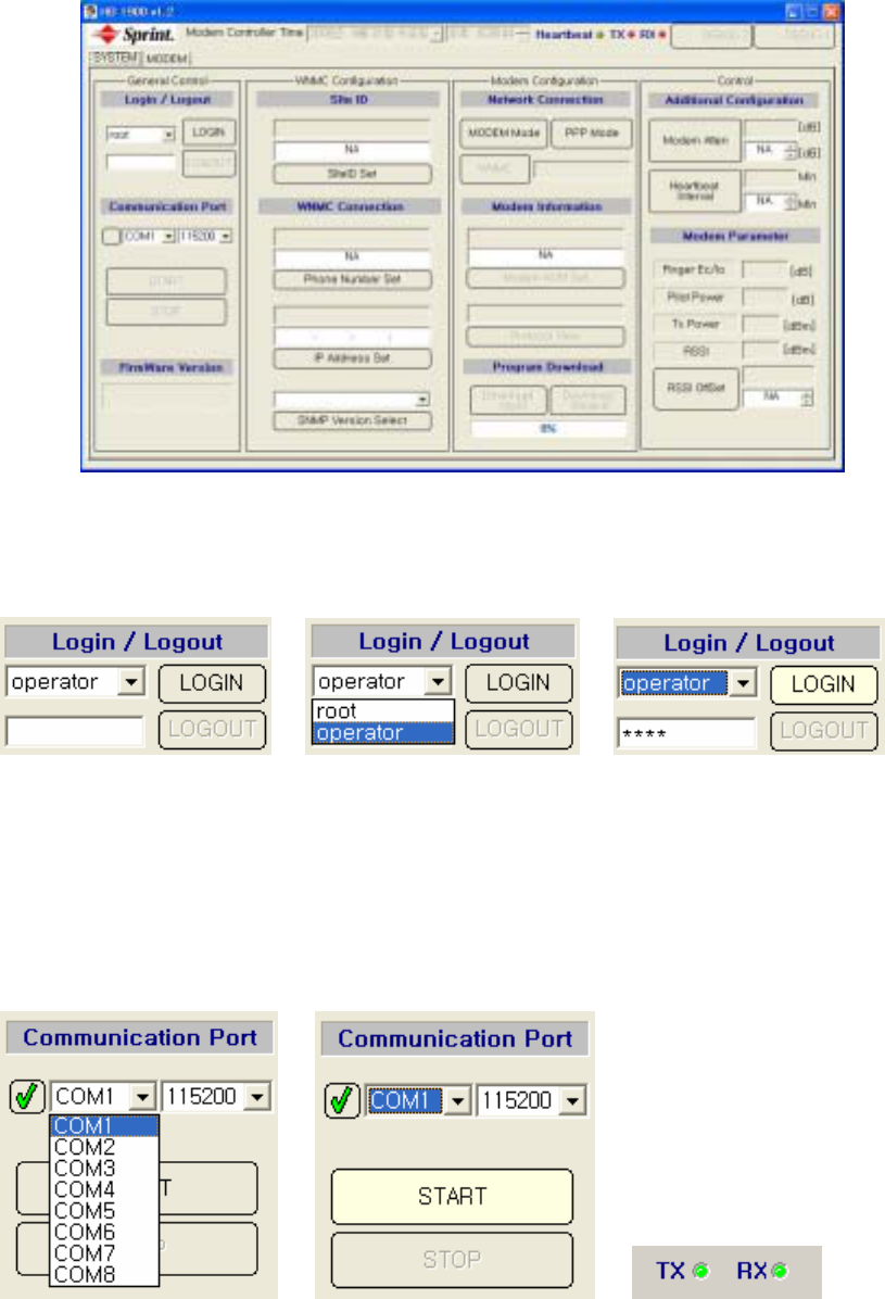
When you click HB 1900 v1_2.exe, you will see the following pop-up window.
4.5 How to use and configure the Graphic User Interface (GUI)
4.5.1 Login / Logout
To proceed using the GUI Program, a user should log-in.
There are two kinds of users. One is the‘root’ and the other is the‘operator’. The ‘root’ user, the
can control all GUI buttons but the ‘operator’, can not use debugging pop-up window. Input
classified user IDs(‘root’ or ‘operator’) and assess password. After that,all default buttons will be
activated.
4.6 How to set up a communication port
After setting up the GUI Login, you should set up the communication port between the system
R-TRON Proprietary & Confidential Page 13
and GUI. The Communication protocol is a RS-232C protocol between the SNMP board and the
PC serial port which is set up by the GUI. The Current RCU transmit speed is fixed at
11,5200bps. As you can see in the above picture, you can select the proper COM port and then
click the ‘START’ button. Now the RCU communication is started. If there is no problem with the
communication, the Rx LED will light up green with the Tx and Rx lighting up green, alternately.
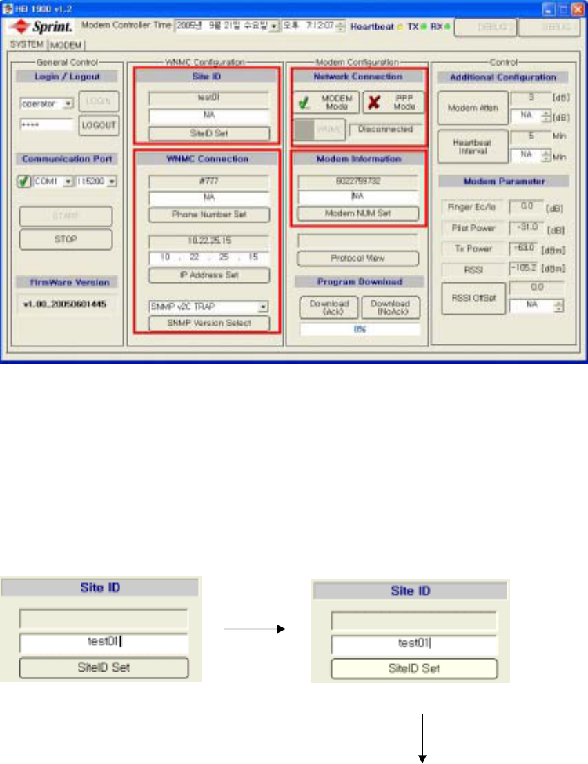
4.7 Check setting figures
As shown in the above picture, you can check the Site ID(Cascade Code) , WNMC Phone
Number , WNMC IP Address , SNMP Version and Modem Phone Number. When you change
the current GUI settings, you can input the needed numbers in the white boxes and click toggle
switch to store the values.
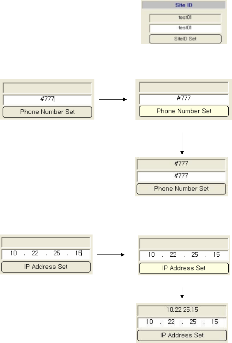
4.7.1 How to set Parameter value
4.7.1.1 Cascade code Input
ex) Cascade Code which is given by a wireless operator : test01
Type Cascade code in white activated box. Click “SiteID Set” button.
R-TRON Proprietary & Confidential Page 14
4.7.1.2 Input WNMC Phone Number
Sprint WNMC Phone Number is #777 and procedures is as followings,
Type “#777” in white activated box Click “Phone Number Set” button
4.7.1.3 WNMC IP Address입력
Sprint WNMC Server IP Address는 10.22.25.15 and procedures is as followings,
Type “10.22.25.15” in white activated box. Click “IP Address Set” button.

R-TRON Proprietary & Confidential Page 15
4.7.1.4 Input Modem Phone Number
Type modem phone number which you are going to put it into HB 1900.
Each modem phone number is different.
For example, when it comes to modem phone Click “Modem NUM Set”
number is 5022759735, type this number
in white activated box.
2.4 How to check Modem
You can set the network connection status in ‘modem mode’ using the modem status pop-up
window and entering information in the ‘modem statistics’ pop-up window as followings,
R-TRON Proprietary & Confidential Page 16
① When the Modem is properly connected, you will see ‘READY’ im green, like in the
above picture[number 1].
② Then you can click the NMST button [number 2] and test the AT Command. When
you see the ‘OK’ response, this means that the modem and SNMP board status is
Okay.
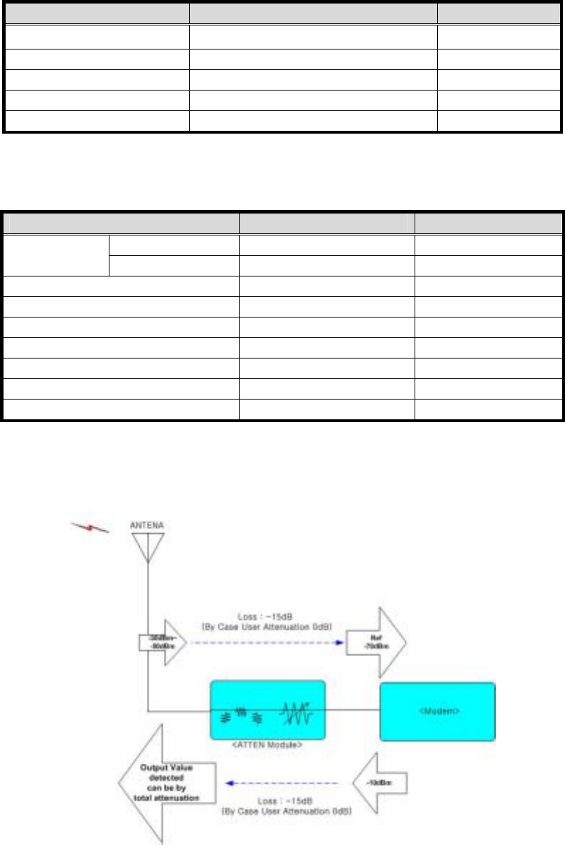
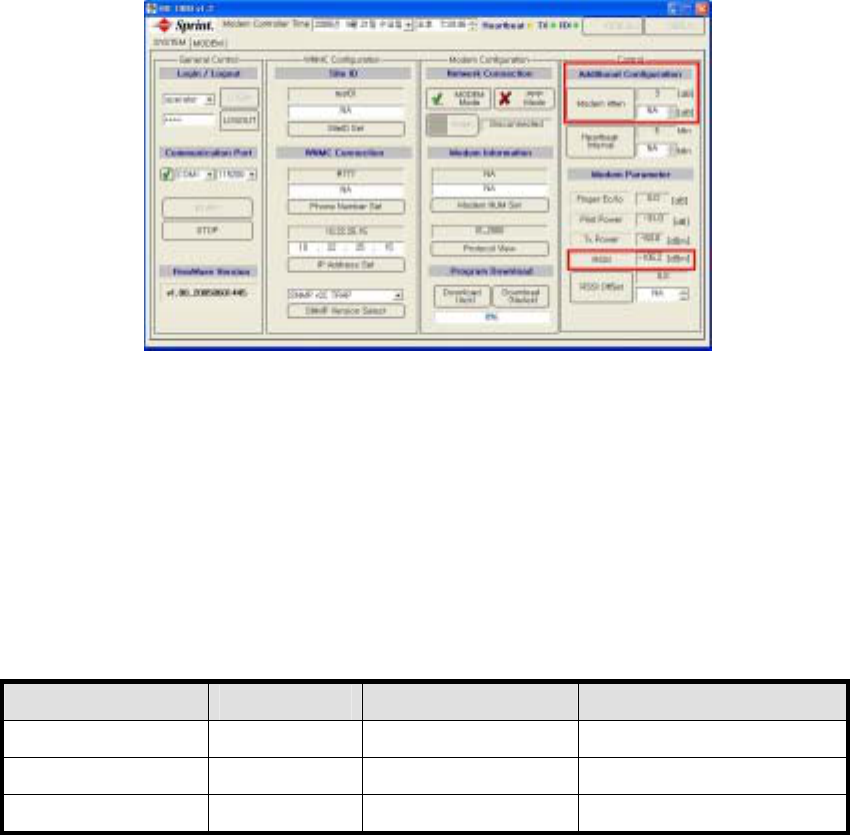
2.5 Check RSSI Value and Set Attenuation
2.5.1 Set Attenuation
After check the RSSI value which is displayed on the GUI, set the RSSI value as -70dBm, using
the modem attenuation. For example, when the GUI RSSI value is -67dBm, you can set it as -
70dBm, using the modem attenuation 3dB. To set the attenuation, you can input the attenuation
value in white box and then click the ‘modem atten’ button which is located on the left side to
store it. (Ex-factory setting value of HB 1900 : user attenuation is 12dB , Heartbeat interval is
5 minutes.)
Ex) How to set User Attenuation
Antenna input Level Fixed Loss User Attenuation Reference RSSI Value
-30dBm -15dB -25 dB -70dBm
-40dBm -15dB -15 dB -70dBm
-50dBm -15dB -5 dB -70dBm
R-TRON Proprietary & Confidential Page 17
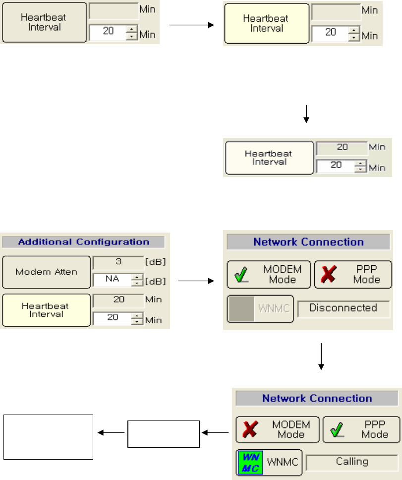
2.5.2 Set Heartbeat Interval
Type heartbeat interval in white Click “Heartbeat Interval” button.
activated box.
(Heartbeat Interval Range : 3 ~59 min)
2.6 How to check PPP connection and heartbeat
Set heartbeat interval as 20 minutes and then change network connection status to ‘PPP Mode’.
Connected
Heartbeat Transmit
Status Check