R tron SN-CAT5DAS CAT-5 DAS TRI BAND REPEATER User Manual 1
R-tron Inc. CAT-5 DAS TRI BAND REPEATER Users Manual 1
R tron >
Contents
- 1. Users Manual-1
- 2. Users Manual-2
Users Manual-1

CAT-5 DAS TRI BAND
(CDMA1900 / iDEN800 / iDEN900)
User’s Manual
Please read this manual before operating this product.
After you finish reading this manual, store it in a safe place for future reference.
Notice
Trademark
R-tron is a registered trademark of R-tron Inc.
Other products and company names mentioned here in this manual might be trademarks or
trade names of their respective owners.
Copyright
Copyright © R-tron Inc. 2000-2010
All Rights Reserved
Any reproduction, distribution, or revisions of any or all portions of this manual is prohibited
without written permission from R-tron Inc.
Notice
This document describes the specifications, installation, and operation of the CAT-5 DAS.
Hardware and software mentioned in this document are subject to continuous development and
improvement. Consequently, there may be minor discrepancies between the information in the
document, performance, and design of the product.
Specifications, dimensions, and other statements mentioned in this document are subject to
change without notice.
Questions or Comments
Address: R-tron Inc. 6402 College Boulevard, Overland Park, KS 66211
Phone: +1-913-344-9977, 1-888-31R-TRON
Fax: +1-913-344-9988
e-mail: info@r-tronamerica.com
Website: www.rtronamerica.com

1
Safety Precautions
Opening the CAT-5 DAS equipment could result in electric shock and may cause severe injury.
Connect the equipment frame ground to the building ground.
Operating the CAT-5 DAS with antennas in very close proximity facing each other can lead to
severe damage to the repeater.
RF EXPOSURE INFORMATION
A minimum separation distance of 7.9 inches (20cm) must be maintained between the user and
the external antenna of the repeater to satisfy FCC RF exposure requirements. For more
information about RF exposure, please visit the FCC website at www.fcc.gov
This equipment is for indoor use only and enables the communication wiring to communicate
inside the building.

2
Contents
1. Introduction............................................................................................................................................5
2. Description..............................................................................................................................................8
2.1 MHU Unit Overview….........……………….………………….………………………………….……………………….…………….………...8
2.1.1 MHU Internal Configuration…………………………………………………………………………………………………………..9
2.1.2 MHU CDMA1900 and iDEN800/900 UDC Module………………………………………………...….………………..10
2.1.3 MHU MCU (Main Control Unit)……………………………………………………………………………………………………11
2.1.4 MHU Interface Board……………………………………………………………………………………………………………………12
2.1.5 MHU C&C (Common & Control Unit)…………………………………………………………………………………………12
2.1.6 MHU PSU (Power Supply Unit)………………………………….…………………………………………………………………13
2.2 Remote Unit Overview….….………………………..………….……………………………………………..………….………………….....14
2.2.1 Remote Internal Configuration………………………………………………………………………………………..…………..15
2.2.2 Remote CDMA1900 UDC Module……………………………………………………………………………………………….15
2.2.3 Remote iDEN800/900 UDC Module………………………………………………………………………………………........16
2.2.4 TRI BAND MUX Filter………………………………………………………………………………………………….....…………….16
2.2.5 Remote MCU (Main Control Unit)…………………………………………………………………………………...…………..17
2.2.6 Remote Interface Board…………………………………………………………………………………………………………...…..18
2.2.7 Remote PSU (Power Supply unit)…………………………………………………………………………………………………18
2.3 EHU Unit Overview…….…….…………………………………….….……………………………..…………………….………………………19
2.3.1 EHU Internal Configuration…….………………………………………………………………………………………………...….19
2.3.2 EHU Interface Board...………….…………………………………………….…………………………………………......………....20
2.3.3 EHU RFU……………………………………………………………………………………………………………………………………….21
2.3.4 EHU MCU (Main Control Unit)….………………………………………………………………………………………………….21
2.3.5 EHU PSU (Power Supply Unit)….…………………………………………………………………………………………………..22
3. Hardware Installation .........................................................................................................................23
3.1 Check List of Items…………………..………………………………………………………………………………………………………….....23
3.1.1 MHU of Items……………………………………………………………………………………………………………………………….23
3.1.2 Remote of Items………………………………………………………………………………………………………...…………………24
3.1.3 EHU of Items…………………………………………………………………………………………………………..….…………………24
3.2 Mounting.…………………………………………………………………………………………...…………………………………………………..25
3.2.1 Remote Mounting…………………………………………………………………………………………………...……………………25
3.2.2 MHU & EHU Mounting………………………………………………………………………………………………………………..27
3.3 Grounding…..………………………………………………………………………………………………..…………………………………………28
3.4 Power On………………………………………………………………………………………………..………...…………………………………….29

3
4. Operation ......................................................................................................................................…….30
4.1 System Requirements…...…………………………...……..………………………….…………………………………………………………30
4.2 Network Setup…..……………………………………………..…………….………………………………………………………………………30
4.2.1 Windows XP……...………………………….…………………………………………………………………………………...………….30
4.2.2 Windows 2000……………………………………………………….……………………………………………………………………..32
4.2.3 Windows Vista………………………………….…………………………………………………………………………………………..34
4.2.4 Windows 7……………………………………………………………………………………………………………………………………37
4.3 System Log in…………………….………………………………………………………………………………………..………………………….41
4.4 System Setup………….…………..…………….…………………………………………………………....……………………………………...43
4.4.1 Security…………….……………………………………………………………………..…………………………………………………….43
4.4.2 Clock………………….……………………………………………………..…………………………………………………………………..43
4.4.3 Network…………….…………………………………………………………………………………………………………………………..44
4.4.4 Control……………….……………………………...………………………………………………………………………………………….47
4.4.5 Firmware Upload…..........................................................................................................................................................55
4.4.6 Reboot………………….……………………………………………………………………………………………………………………….56
4.4.7 Log Out………..……………………………………………………………………………………………………………………………….56
5. Troubleshooting……………….…………………………………………..………………………….………...….57
6. Specifications..……...…………………….…………………………………..…………….…………..................62
7. Appendix…….…..………………………………….…………………………..………………………..................67

4
Glossary
The following is a list of abbreviations and terms used in this manual.
Abbreviation Definition
AC Alternating Current
ANT Antenna
ATT Attenuator / Attenuation
MHU Main Hub Unit
RU Remote Unit
EHU Extension Hub Unit
C.W Continuous Wave
GUI Graphic User Interface
LED Light Emitting Diode
PLL Phase-locked loop
PSU Power Supply Unit
MCU Main Control Unit
UDC Up-Down Converter
DL Downlink
GND Grounding
RF Radio Frequency
RSSI Received Signal Strength Indication
TEMP Temperature
DC Direct Current
UL Uplink
VSWR Voltage Standing Wave Ratio
CLC Cable Loss Compensation
ALC (Automatic Level Control)
ALC feature prevents the repeater from exceeding its maximum output power by reducing the gain
automatically. ALC is used to adjust the gain to an appropriate level for a range of input signal levels.
ASD (Automatic Shutdown)
Automatic shut down protects the repeater from oscillation or excessive input signal and eliminates
any degradation to the network.
There are three parameters: ASD Level, ASD Time, and ASD Iteration.
If the output power exceeds higher than the “ASD LEVEL”, the repeater will shut down for “ASD
TIME” seconds and it will turn the amp back on to measure the output power again. If this repeats at
“Iteration” times, the repeater will shut down completely.
5
1. Introduction
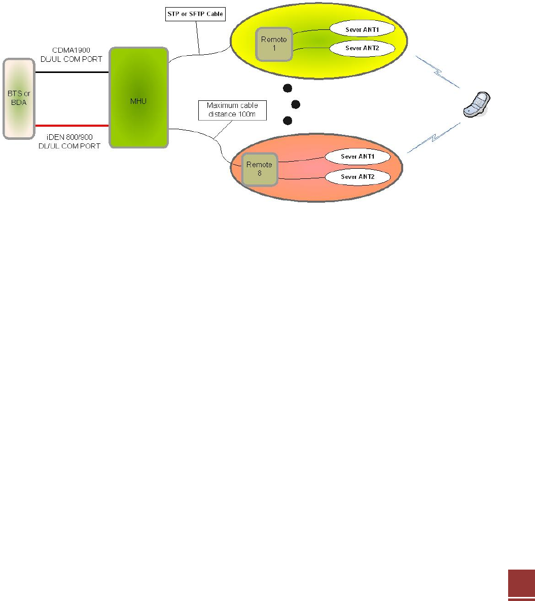
• The CAT-5 In-building DAS consist of a MHU unit and a maximum of 8 remote units. Each
remote unit can have up to 2 server antenna ports so that one MHU has the ability to provide
up to 16 server antennas. The MHU and the remote unit are interconnected using the analog
CAT5e method so that the system can simultaneously provide TRI Band.
(CDMA1900 / iDEN800 / iDEN900) service to multiple floors in the building.
< Basic Organization >
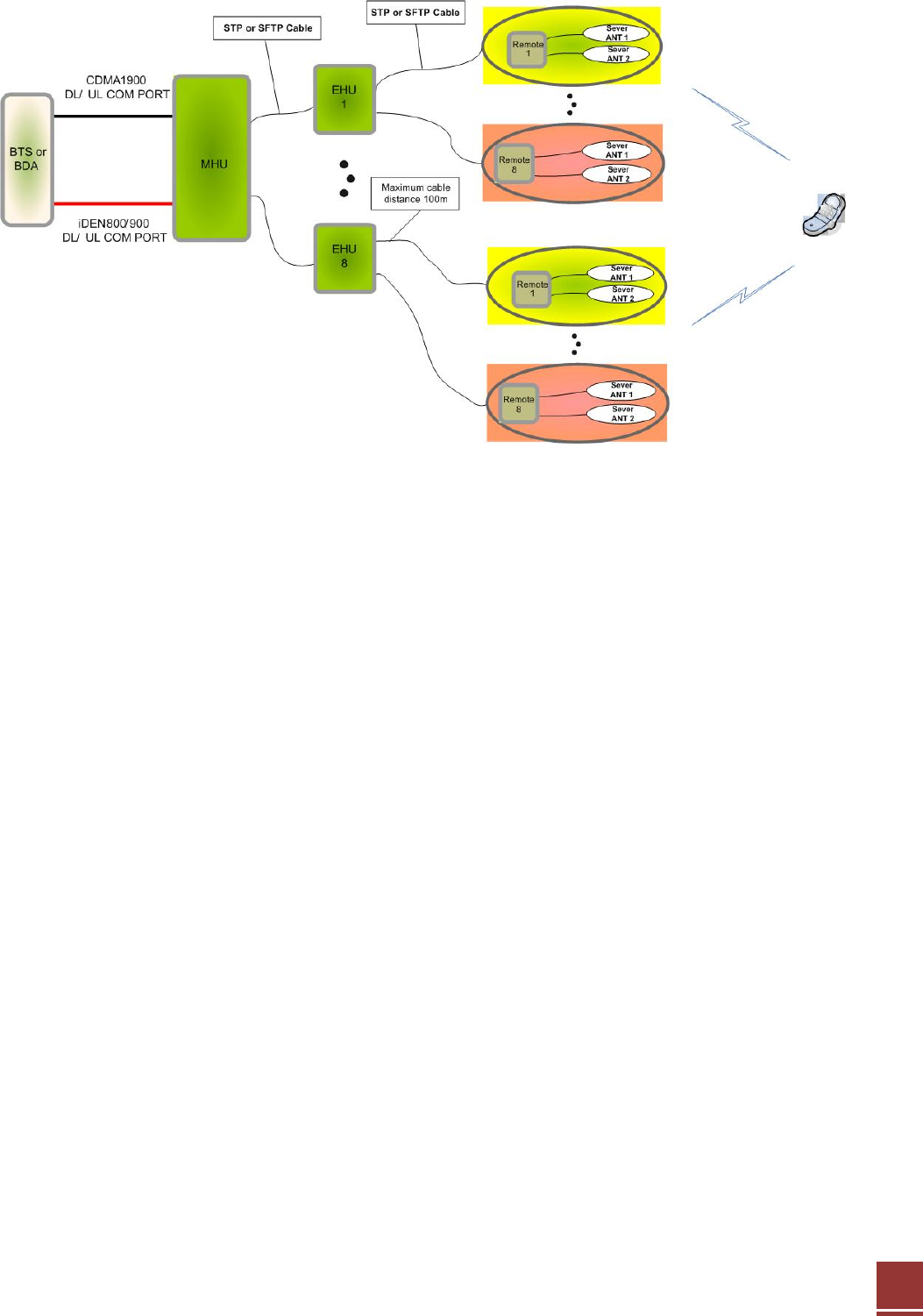
• If EHU unit is added between MHU and Remote at the CAT-5 In-building DAS composition, it
will be a composition like below. MHU is able to connect EHU 8EA and every EHU unit
connects Remote 8EA. Thus, Remote can be connected maximum 64EA.
6
< Organization with EHU >
1-1. MHU
MCU & Interface Unit components
¾ Power Supply Unit (PSU)
¾ Main Control Unit (MCU)
¾ MHU Interface Unit
¾ Command & Control Unit(C&C)
RF UDC Unit components
¾ CDMA 1900 DL/UL UDC Unit
¾ iDEN 800/900 DL/UL UDC Unit
PoE Unit components (Option)
¾ PSU
¾ PSE
The MHU Unit can detect input signals from the TRI Band (CDMA1900/iDEN800/iDEN900).
The input signals are changed into IF analog signals by UDC for the transmission using the STP
or SFTP cable and then the IF analog signals are transmitted to 8 temotes through the interface
board.

7
1-2. Remote
Remote Unit components
¾ Power Supply Unit (PSU)
¾ Power Supply Unit (PD)-PoE Option
¾ iDEN 800/900 UL/DL UDC Unit
¾ CDMA 1900 UL/DL UDC Unit
¾ TRI Band MUX Filter
¾ Main Control Unit (MCU)
¾ RU Interface Unit
The Remote UDC Module converts the RF signal into an IF signal and compensates it for the
STP or SFTP Cable loss. After the RF signal is amplified from the UDC module, it goes to all
antenna ports from the remote until.
1-3. EHU(External Hub Unit)
EHU components
¾ Power Supply Unit (PSU)
¾ RFU
¾ EHU Interface Unit
¾ Main Control Unit (MCU)
PoE Unit components (Option)
¾ PSU
¾ PSE
EHU gets converting IF signal at MHU through STP or SFTP cable. Inputting IF signal transmits IF
signal to Remote after compensating STP or SFTP cable loss through RFU of EHU.
8
2. Description
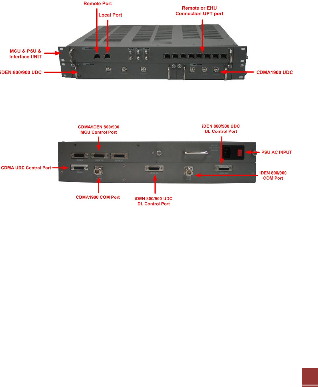
2.1 MHU(Main Hub Unit) Overview
MHU unit is made up of MCU&Interface Unit 1U and RF UDC Unit 1U
< Front View >
< Rear View >
9
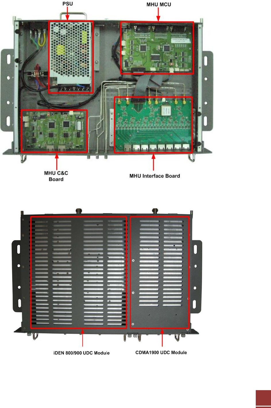
2.1.1 MHU Internal Configuration
<MCU & PSU & Interface UNIT
<UDC Module UNIT>
10
2.1.2 MHU CDMA1900 and iDEN800/900 UDC MODULE
< CDMA1900 UDC Module >
< iDEN 800/900 UDC Module >
11
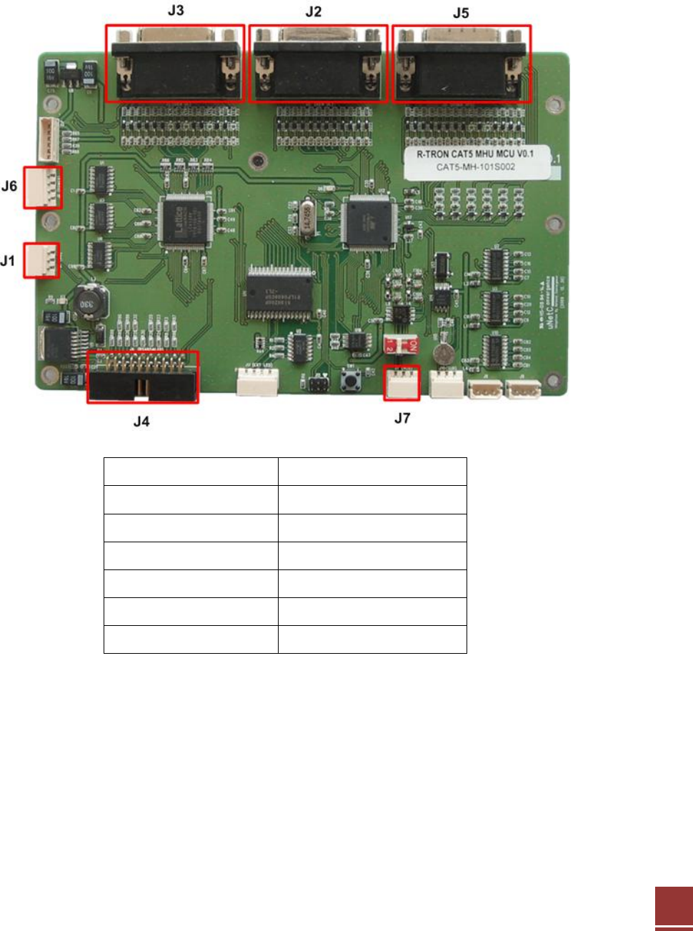
2.1.3 MHU MCU(Main Control Unit)
The MCU (Main Control Unit) is the control unit of the CAT5 DAS MHU. It controls and
monitors operational parameters. It is also responsible for generating alarms, keeping event
logs and performing many other functions.
J1 GUI Link
J2 iDEN RFU DL Control
J3 iDEN RFU UL Control
J4 RS485 & LED
J5 CDMA RFU Control
J6 Power
J7 CNC Link
12
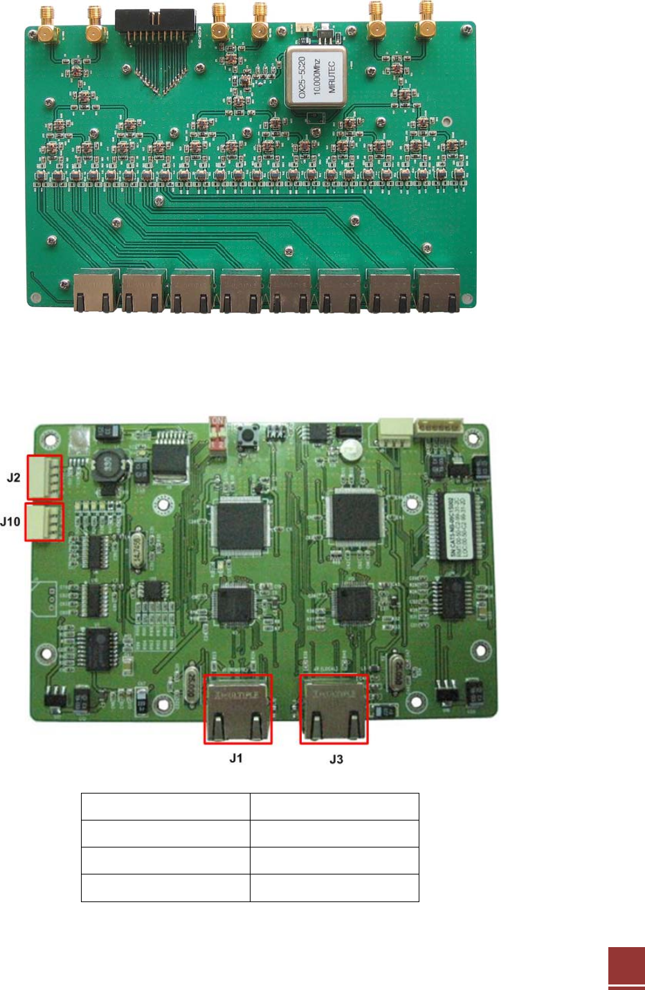
2.1.4 MHU INTERFACE BOARD
2.1.5 MHU C&C (Command & Control Unit)
C&C Board is communicating board for WEB GUI.
J1 Remote
J2 Power
J3 Local
J10 MCU Link
13
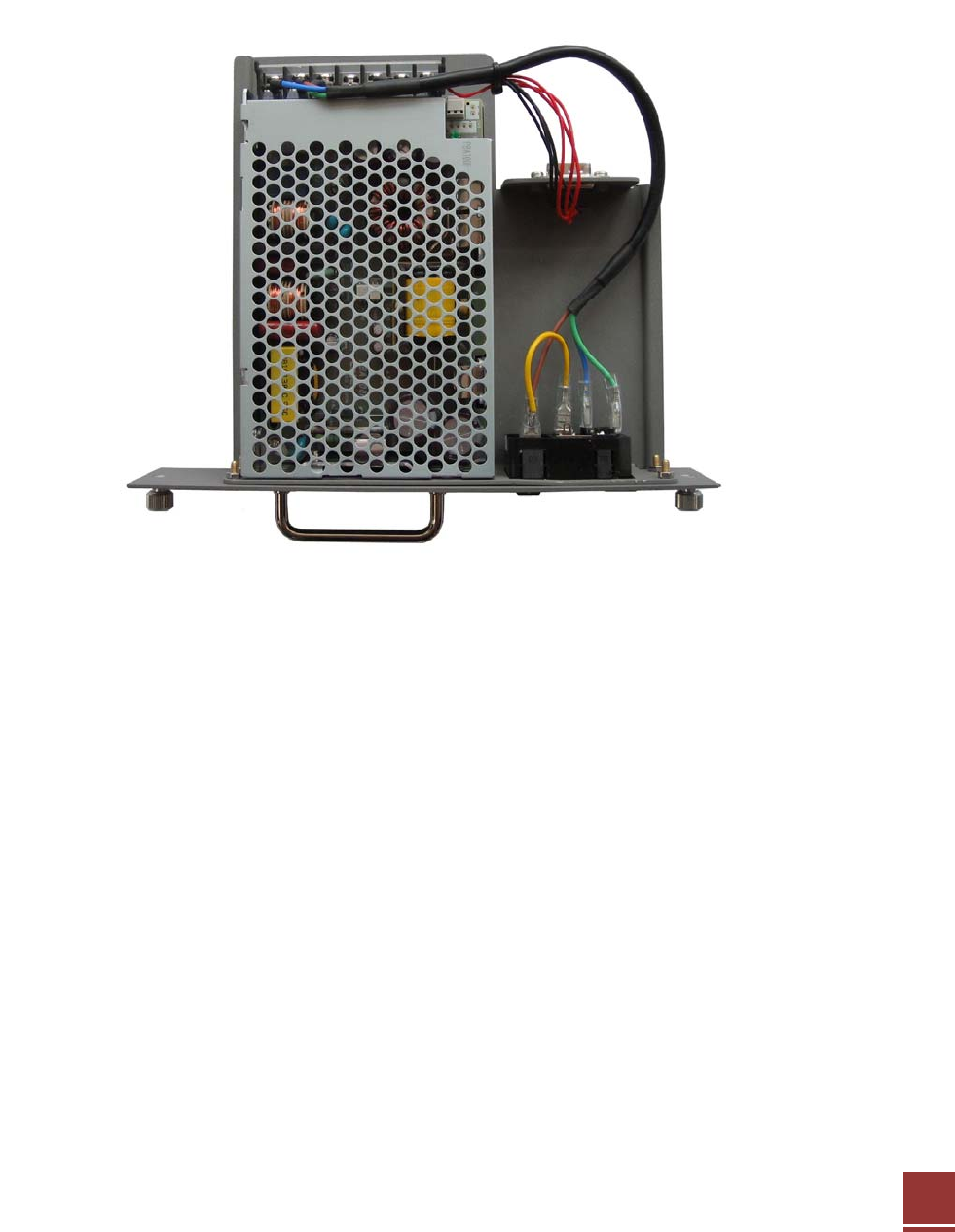
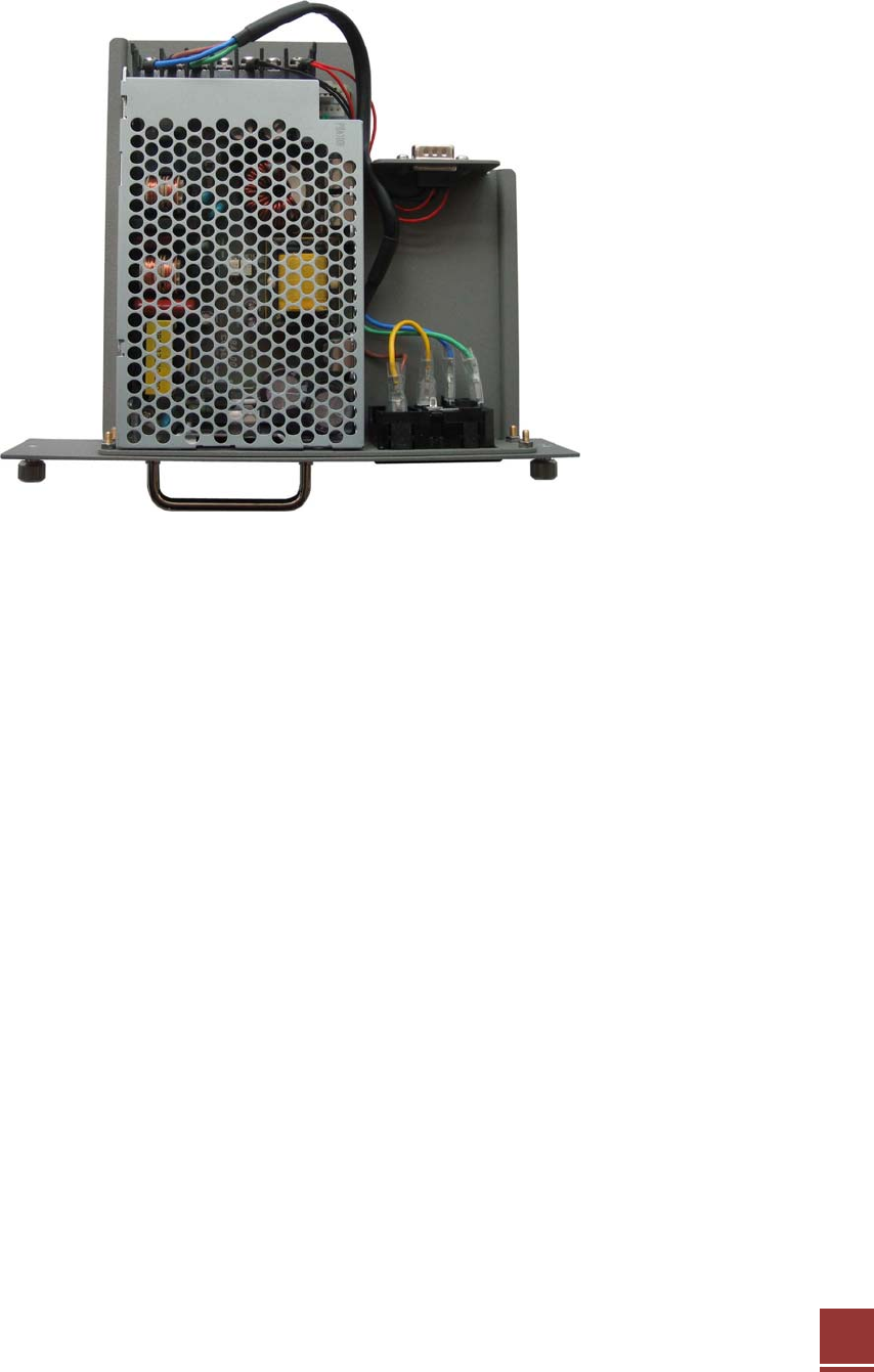
2.1.6 MHU PSU (Power Supply Unit)
The Power Supply Unit (PSU) supplies a steady DC Power to CAT5 DAS MHU by drawing
power from the general in-wall AC outlets.
14
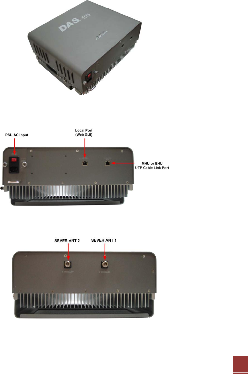
2.2 Remote Overview
The Remote UDC module converts the RF signal into an IF signal and compensates it for
the CAT5e STP or SFTP cable loss. After the RF signal is amplified from the UDC module, it
goes to all antenna ports from the remote unit.
<Front View>
<Bottom View>
<Top View>
15
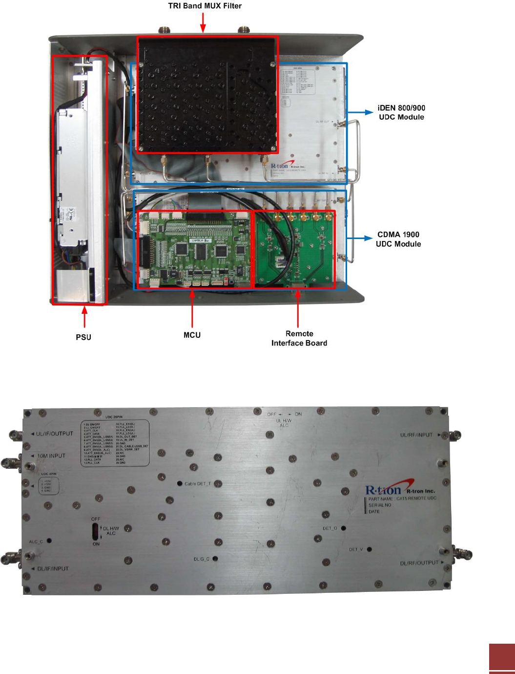
2.2.1 Remote Internal Configuration
2.2.2 Remote CDMA1900 UDC Module
16
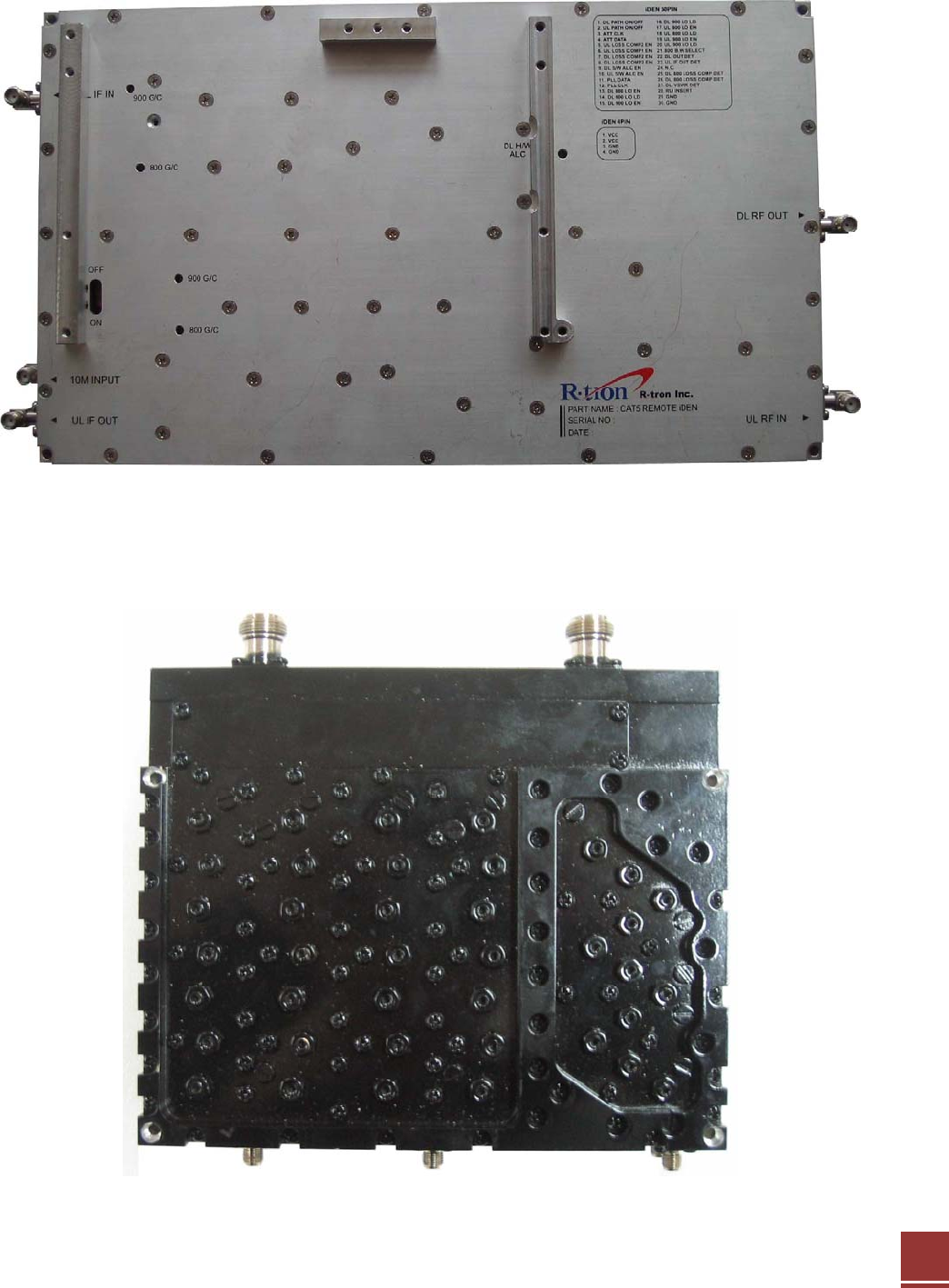
2.2.3 Remote iDEN 800/900 UDC Module
2.2.4 TRI BAND MUX Filter
17
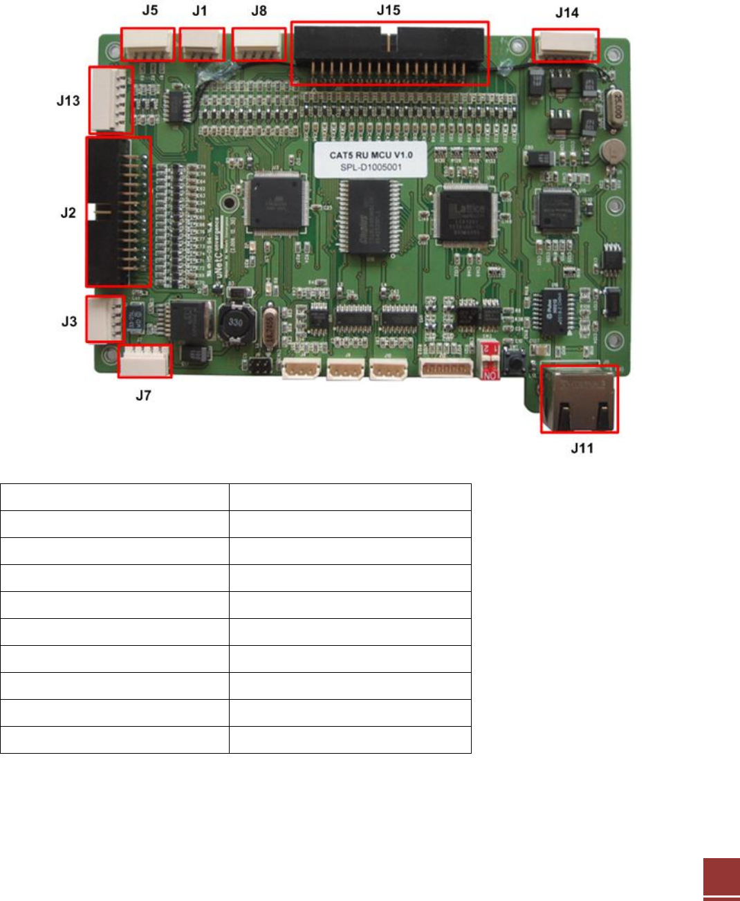
2.2.5 Remote MCU(Main Control Unit)
The MCU (Main Control Unit) is the control unit of the CAT5 DAS Remote. It controls and
monitors operational parameters. It is also responsible for generating alarms, keeping event
logs and performing many other functions.
J1 Factory GUI Link
J2 CDMA Control
J3 CDMA VCC(9V)
J5 LED
J7 Main VCC(9V)
J8 IDEN VCC(9V)
J11 WEB GUI Link
J13 Interface B’D Control
J14 MHU RS485
J15 IDEN Control
18
2.2.6 Remote Interface Board
2.2.7 Remote PSU (Power Supply Unit)
The Power Supply Unit (PSU) supplies a steady DC Power to CAT5 DAS Remote by drawing
power from the general in-wall AC outlets.
19
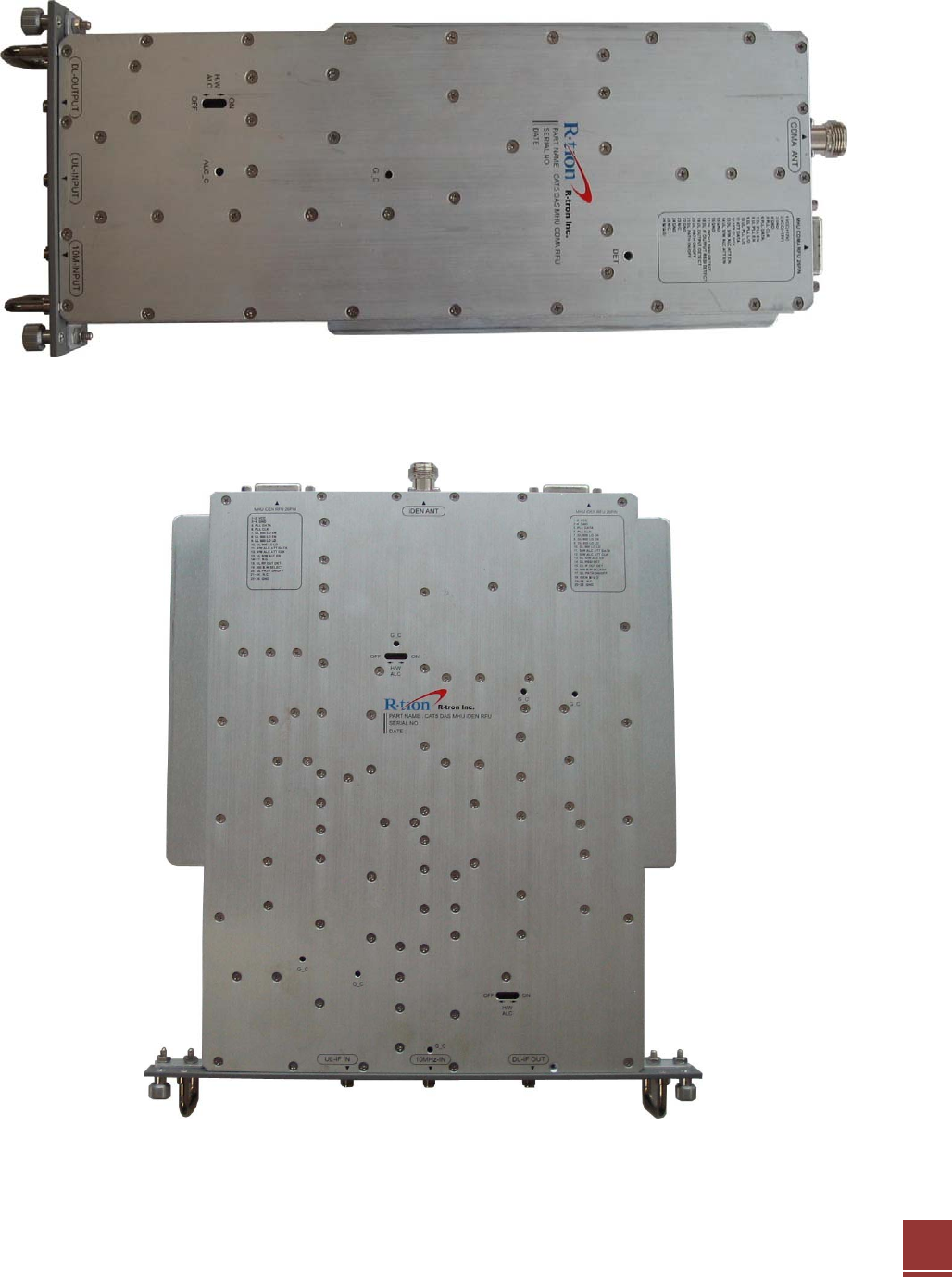
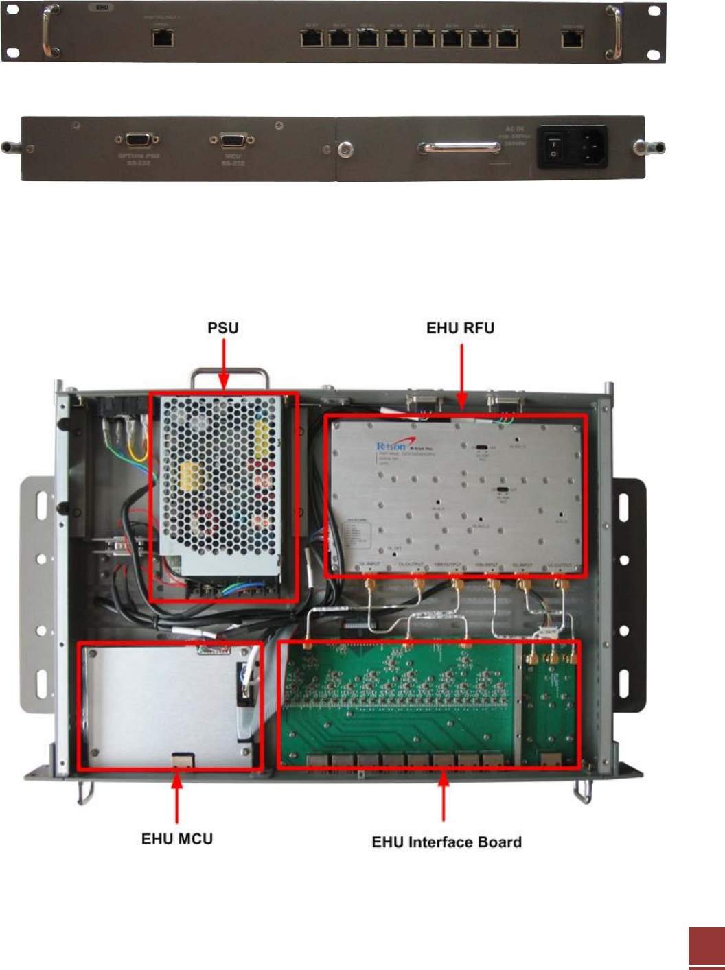
2.3 EHU(Extension Hub Unit)
<Front View>
<Rear View>
2.3.1 EHU Internal Configuration
20
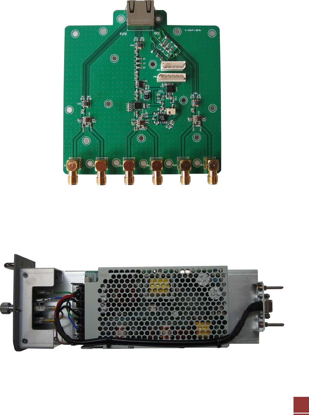
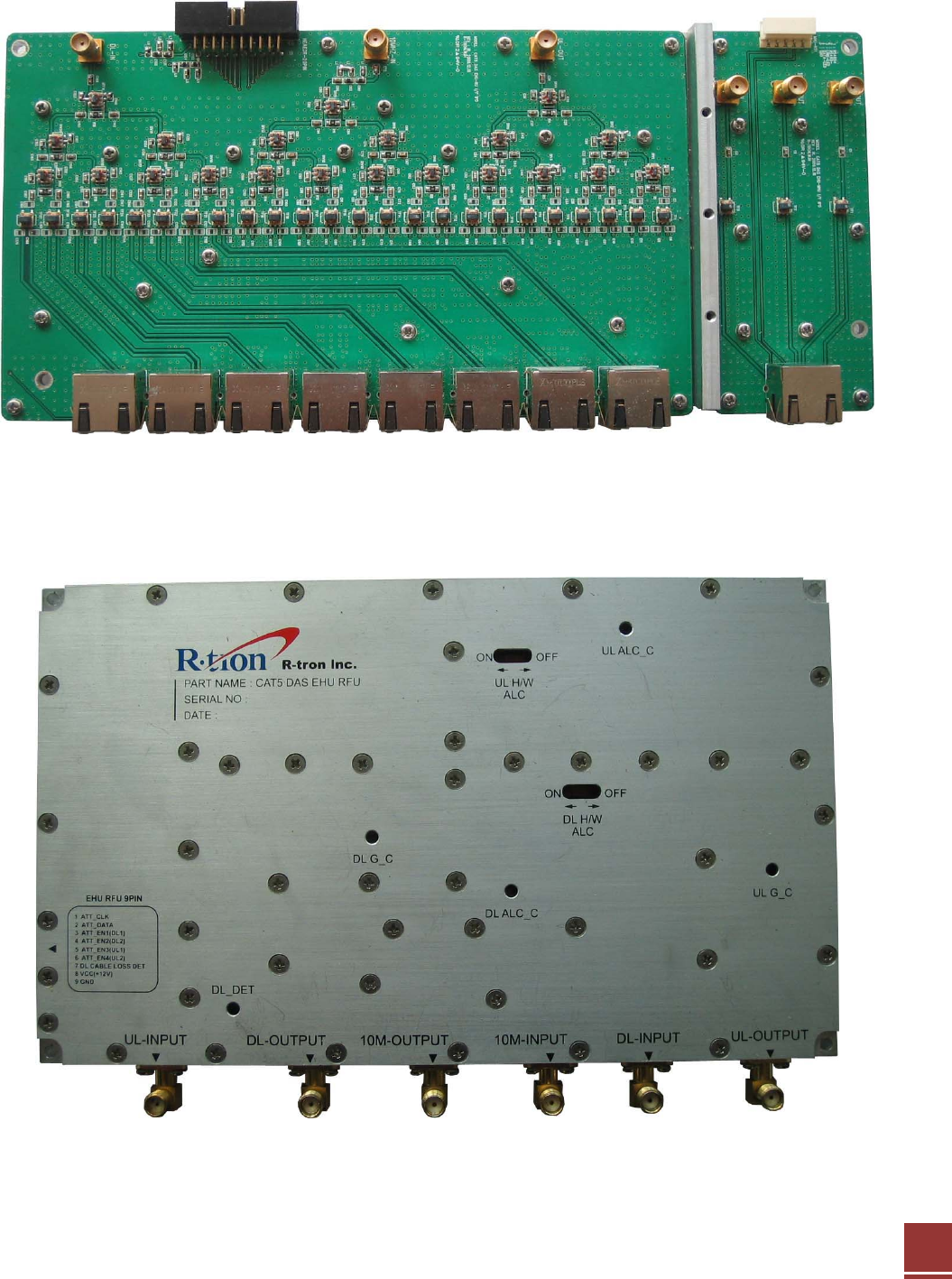
2.3.2 EHU Interface Board
2.3.3 EHU RFU
RFU transmits IF signal to Remote after compensating the STP or SFTP Cable loss.
21
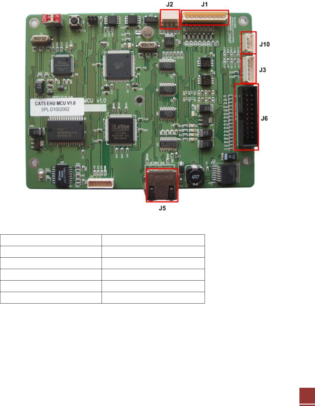
2.3.4 EHU MCU(Main Control Unit)
The MCU (Main Control Unit) is the control unit of the CAT5 DAS EHU.
J1 RFU
J2 GUI
J3 MHU RS485
J5 WEB GUI
J6 RU RS485
J10 PSU RS-232
22
2.3.5 EHU PSU (Power Supply Unit)
The Power Supply Unit (PSU) supplies a steady DC Power to CAT5 DAS EHU by drawing
power from the general in-wall AC outlets.
23
3. Hardware Installation
The installation procedure is as follows:
• Check List of Items
• Mounting
• Grounding
3.1 Check List of Items
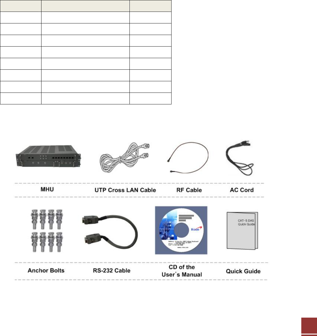
3.1.1 MHU of Items
Index Items Quantity
1 MHU Set 1
2 UTP Cross LAN Cable 1
3 AC Cord 1
4 Anchor Bolts 8
5 RF Cable 6
6 RS-232 Cable 3
7 CD of the User’s Manual 1
8 Quick Guide 1
Item Figure
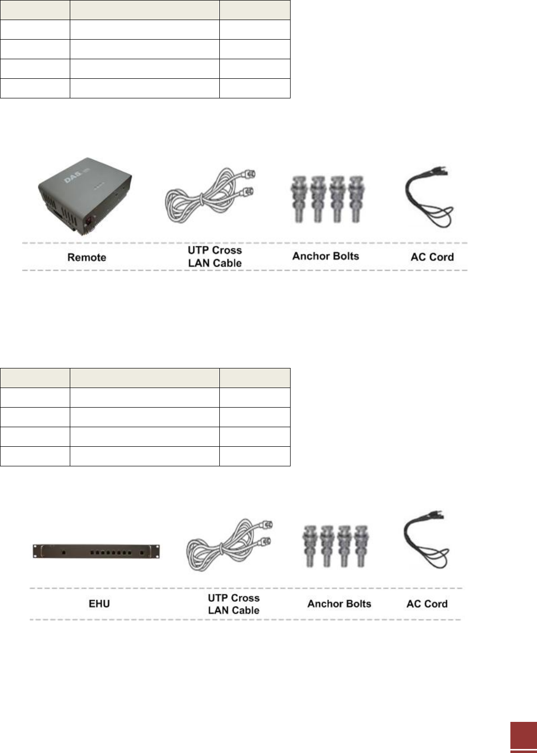
3.1.2 Remote of Items
24
Index Items Quantity
1 Remote Repeater 1
2 UTP Cross LAN Cable 1
3 AC Cord 1
4 Anchor Bolts 4
Item Figure
3.1.3 EHU of Items
Index Items Quantity
1 EHU 1
2 UTP Cross LAN Cable 1
3 AC Cord 1
4 Anchor Bolts 4
Item Figure
25
3.2 Mounting
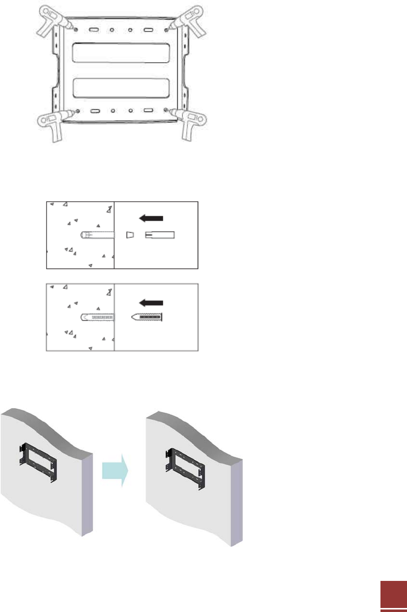
3.2.1 Remote Mounting
CAT-5 DAS are easy to mount using the assembled mounting bracket, which has 4 holes for the
provided 5/16” fixing screws.
Step 1: Drill holes directly through the template.
Step 2: Install the set anchor bolts or the plastic anchor bolts in the holes.
Step 3: Attach the mounting bracket to the wall using provided bolts or extra screws.
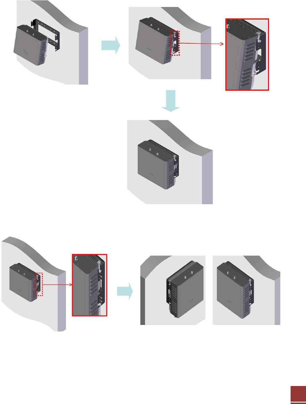
26
Step 4: Lean the CAT-5 DAS RU to hang topside of the Guide Ring on the mounting bracket,
and push toward the wall to mount.
Step 5: Fix the CAT-5 DAS RU using the 6 screws provided.
27
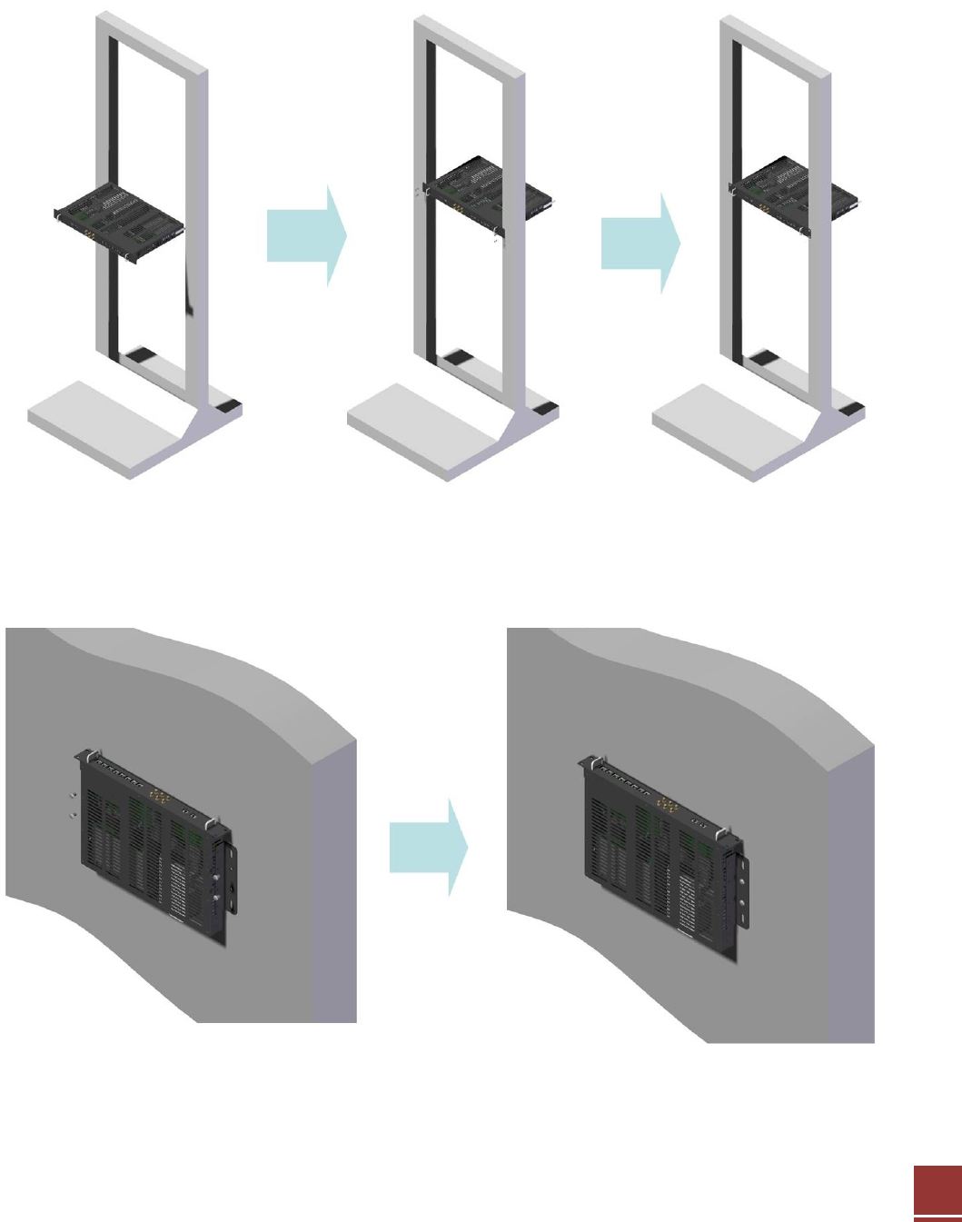
3.2.2 MHU & EHU Unit Mounting
MHU & EHU Unit of CAT-5 DAS is able to install at the Wall or Rack
CAT-5 DAS MHU & EHU Unit의 Rack Installation
CAT-5 DAS MHU & EHU unit의 Wall installation
MHU and EHU Unit size is same. Repeat the step 1 to step 3 of 3.2.1 then install it as the same
way.
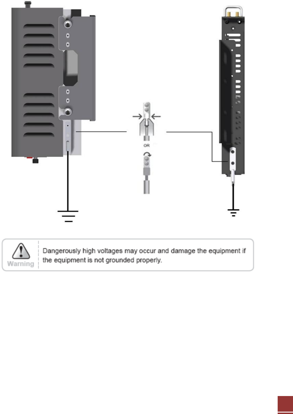
3.3 Grounding
28
A rod on the left side is intended for a building ground. Connect the ground cable to the rod.
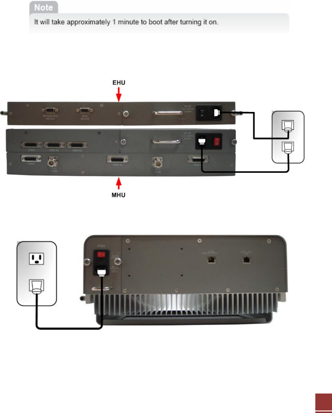
3.4 Power On
29
Step 1: Connect the power cord.
Step 2: Plug the power cord into a wall outlet.
Step 3: Power Switch turns on.
Step 4: Check if the green LED at the top turns on.
<MHU and EHU Power ON>
<Remote Power ON>
30
4. Operation
4.1 System Requirements
CAT-5 DAS operates on a customer provided PC based platform with the following system
requirements:
• Windows® 2000, Windows® XP or Windows® Vista, Windows 7
• Internet Explorer 6.0(Recommended) or higher
• 128 MB RAM or higher
• Pentium Ⅲ processor or higher
• RJ-45 jack required
4.2 Network Setup
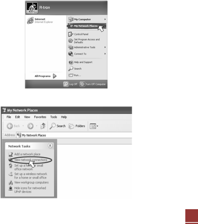
4.2.1 Windows XP
Step 1: Click the Start button and select My Network Places.
Step 2: Click View network connections.
31
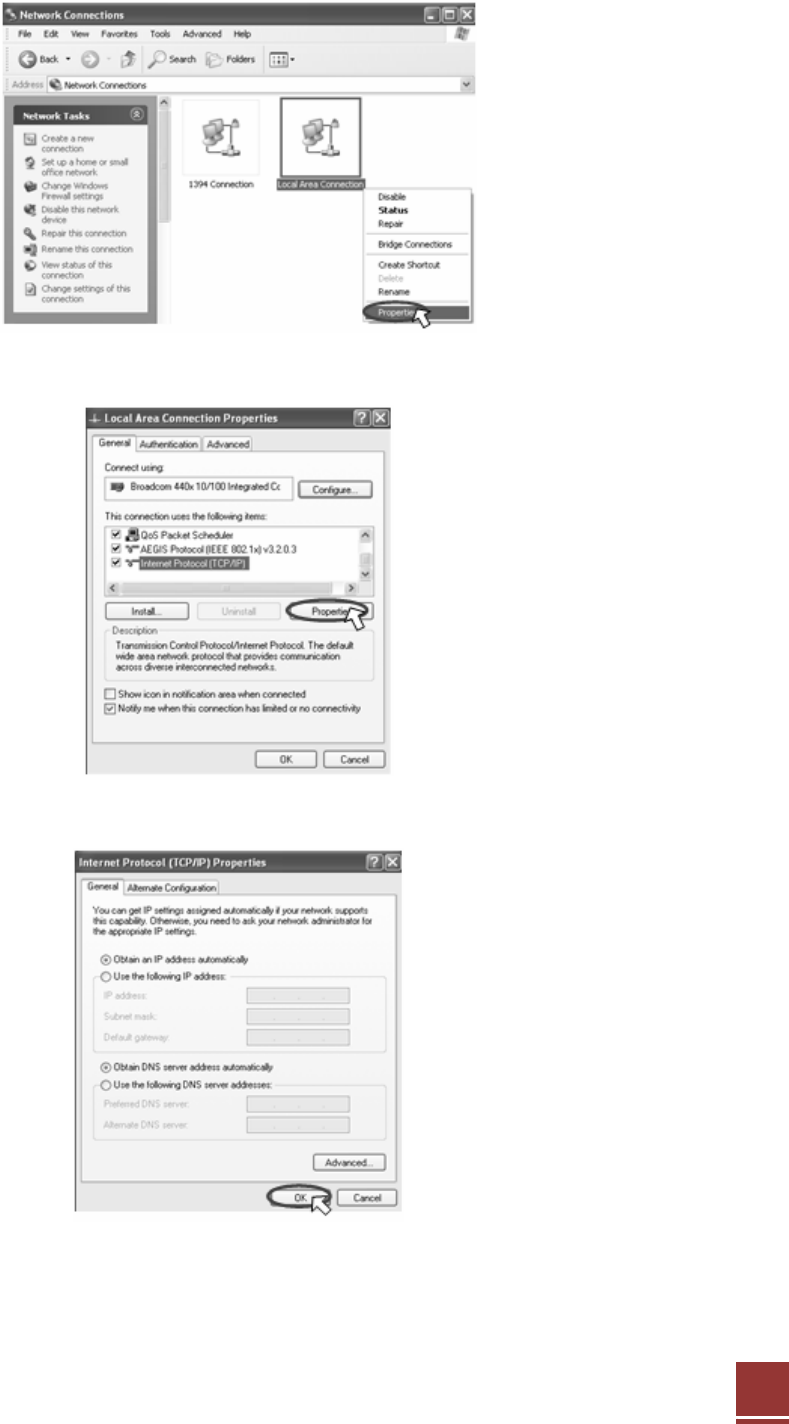
Step 3: Right-click on the Local Area Connection and select Properties to view the shortcut
menu.
Step 4: Select Internet Protocol (TCP/IP) and click Properties.
Step 5: Check Obtain an IP address automatically and click OK.
Step 6: Close all widows.
32
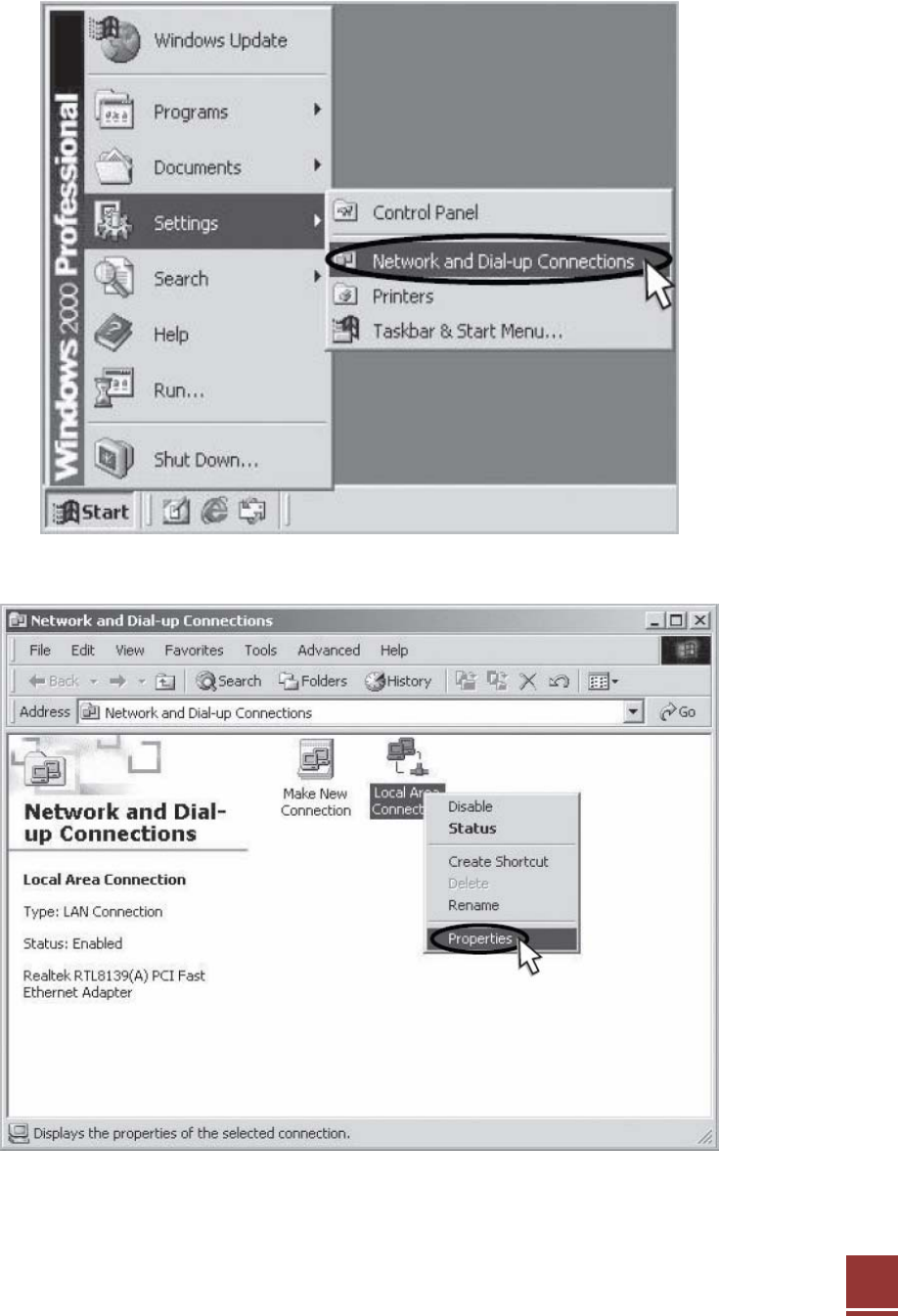
4.2.2 Windows 2000
Step 1: Click the Start button, point to Settings, and then click Network and Dial-up
Connections.
Step 2: Right-click Local Area Connection to see a shortcut menu and click Properties.
33
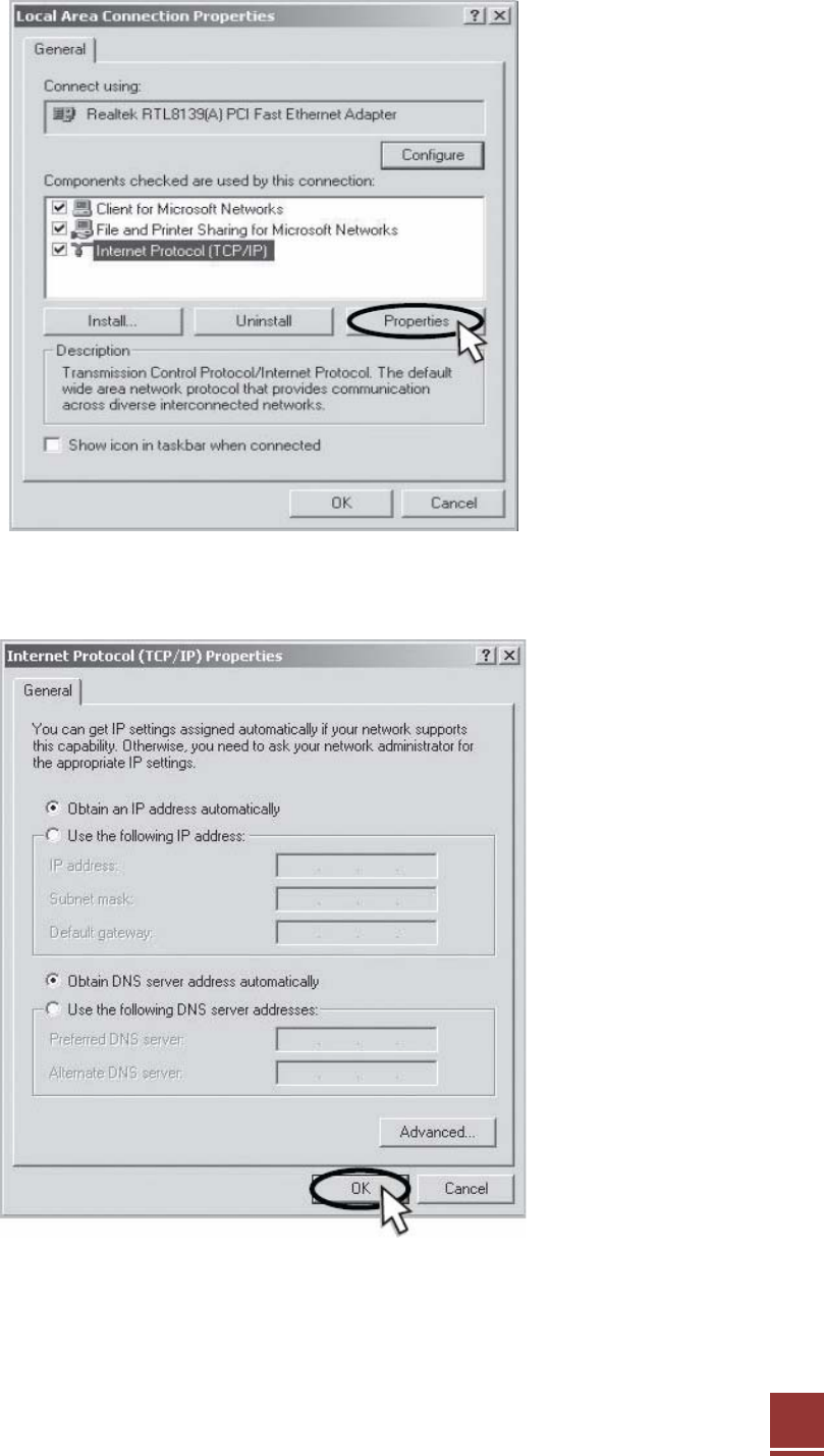
Step 3: Select Internet Protocol (TCP/IP) and click Properties.
Step 4: Check Obtain an IP address automatically and click OK.
Step 5: Close all windows.