R tron SN-CAT5DAS CAT-5 DAS TRI BAND REPEATER User Manual 1
R-tron Inc. CAT-5 DAS TRI BAND REPEATER Users Manual 1
UserManual.wiki
>
R tron
>
SN-CAT5DAS User Manual
>
Users Manual-1
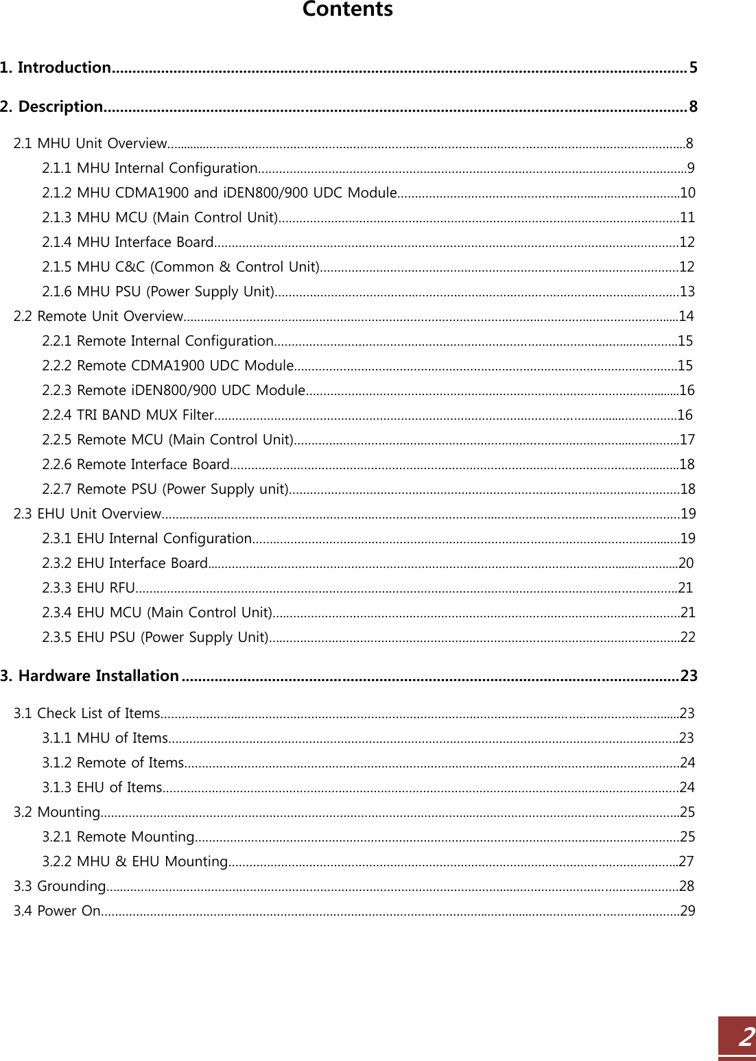
Contents
1.
Users Manual-1
2.
Users Manual-2
Users Manual-1
Navigation menu
Upload a User Manual
Namespaces
Wiki Guide
HTML
PDF
Info
Views
User Manual
Discussion / Help
Navigation