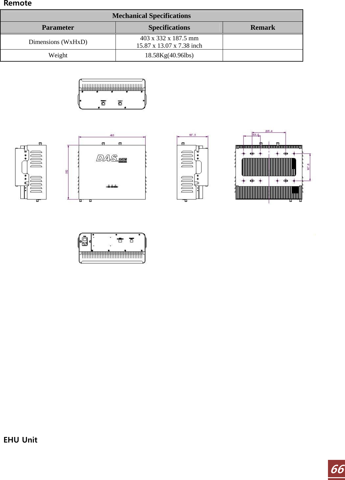
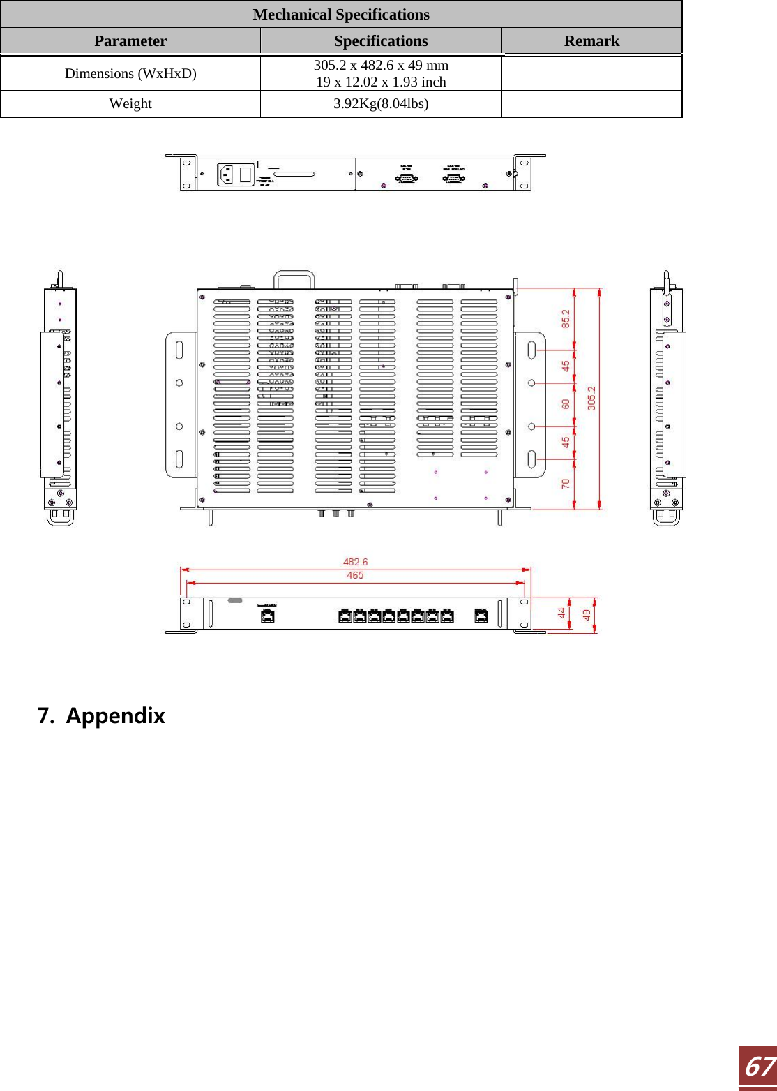
R tron SN-CAT5DAS CAT-5 DAS TRI BAND REPEATER User Manual 2

R-tron Inc. CAT-5 DAS TRI BAND REPEATER Users Manual 2

Contents

Users Manual-2

  344.2.3 Windows Vista Step 1: Click the Start button and select Control Panel.    Step 2: Click Network and Internet.
  35Step 3: Click Network and Sharing Center.    Step 4: Click View status of Local Area Connection.
  36Step 5: Click Properties and a caution pop-up window will appear. Click OK.    Step 6: Select Internet Protocol Version 4 (TCP/IPv4) and click Properties.
  37Step 7: Check Obtain an IP address automatically and click OK.    Step 8: Close all windows.   4.2.4 Windows 7  Step 1: Click the Start button and select Control Panel.
  38Step 2: Click Network and Internet.    Step 3: Click Network and Sharing Center.
  39Step 4: Click View status of Local Area Connection.    Step 5: Click Properties and a caution pop-up window will appear. Click OK.
  40Step 6: Select Internet Protocol Version 4 (TCP/IPv4) and click Properties.    Step 7: Check Obtain an IP address automatically and click OK.    Step 8: Close all windows.
  414.3  System Login  Step 1 Open your Web browser and type http://192.168.0.1 into the URL address box.           Then press the Enter key.    Step 2 The login screen will appear. Type  “operator”  for the ID and  “rtron”  for the password and then Click OK.     Step 3 The pop-up message for the login success will appear. Click OK.
  42Step 4 When the login process is complete, the initial screen will appear.
  434.4  System Setup  4.4.1 Security  The operator does not have authorization to access this menu.  4.4.2 Clock  Click Clock on the left menu bar.   In this menu, you can set the date and time.  Click Set Date/Time
  444.4.3 Network  Click Network on the left menu bar.     Network Setup  • Cascade  Code:  Type the pre-assigned cascade code. Otherwise, you cannot access  the system setup.  • Location Information: Enter the latitude and longitude of information, otherwise you cannot access the system setup. You can input values either in Decimal Degrees or Degrees-Minutes-Seconds.         [Example]         (‘N/S’ | ‘E/W’) ddd.dddddd: (Latitude: N 39.006967 Longitude: W 94.532306)  • Heartbeat Interval: Sets the time to transmit the Heartbeat to the NMC Server.       (Default value is 20 minutes. For this operation test, temporarily reduce the value to 1 minute. After conforming the heartbeat report, set the value back to 20 minutes.)  • Product Information: This is for manufacturer use only. Do not change this value.  • IP Mode: Has two modes, Auto and Static. The factory default is set to IP Mode Auto.   It can be assigned IP automatically if the IP Mode is Auto. IP Mode  has  to  be changed to Static if user wants to set up the IP directly. IP Mode is able to use if Remote port accessed and IP Mode has to set up the static if Remote port accessed.
  45• Access Web GUI on IP Mode Static (Remote Port connection)   - Local IP Setting   Step 1 Repeat Step 1 through 4 on page    Step 2 Check Use the following IP address and enter the manual IP configuration. And then, click OK.    Step 3 Open your Web browser and type  “http://192.168.0.1”  into the URL address box.     Then press the Enter key.  - URL address for the remote access    Open your Web browser and type the manual IP address into the URL address box. Then press the Enter key.  [Example]      Web GUI access URL is http://192.168.0.18
  46  User Note • Location Information: Type the location information such as the building name, address, city, state, zip code and telephone, and then click SAVE. • Donor Site Information: Type the base station’s ID, and then click SAVE. • Installer  Information:  Type  the  installer  information  such  as  the  company,  name  and telephone, and then click SAVE. • User Comment: You can store up to 50 comments in the database memory, but the length of each comment is limited to 60 characters.
  474.4.4 Control A. MHU    MHU Link Status  iDEN Control window is appeared if iDEN checked and CDMA Control window is appeared if
  48CDMA checked. Link On/Off : Port On if Link On/Off box checked, if not, Port Off If EHU is displayed with Link On and turn green light on at the Link status, it means that EHU is connected to Port. (If RU is displayed, it means that RU is connected to MHU.) If UKN is displayed with Link On and turn red light on at the Link status, it means that not connection. If communication is failed with Link on, turn red light on at the Link status. If Link Off, turn gray light on at the Link Status.  iDEN Control Page    ① Path Control : DL or UL Path On/Off ② Power Status : DL Input/ Output Power and UL Output Power display ③ Power Control   ALC(Automatic Level Control): DL ALC operates only and ALC Level is 5dBm.       Manual Gain Control: If ALC Off, DL and UL Gain is able to set up.   If ALC On, gain setting is impossible because gain controlling function is inactive.   ④   Up Link Gain Control: If the UL Gain Tracking is ON, the DL and UL will link so that the UL
  49tries to match with the DL by the UL Gain Offset value. If the UL Gain Tracking is OFF, the DL  and  UL  will  work  individually.  (If  ALC  On,  UL  Gain  Tracking  is  On  automatically.  UL Tracking On/Off function is inactive, Basic Gain deviation of DL and UL is -10dB at MHU) ⑤ ASD(Automatic Shut Down): MHU exists UL ASD only. If UL Output Power maintains for 3 seconds(ASD  Time)  at  the  ASD  Level,  it  occurs  Shutdown.  If  Shutdown is repeated 5 times(ASD Count), Easy Max Setup is needed. ⑥ Return To Factory default: Initialize function ⑦ Easy Max Setup: If Easy Max Setup executes, execute after all linked systems initializing. Complete EHU and RU ID setting before executing Easy Max Setup.  Execute Easy Max setup after checking Link status of each unit is normal. * MHU-EHU-RU Link  MHU: DL/UL Path On Æ DL ALC On (ALC Level 5dBm), UL Gain Tracking On (UL Gain Offset -10dB)   EHU: CLC On(Output 5dBm) Æ Operating CLC from the Min Gain   (UL Gain is linked to DL Gain)  RU: RU CLC On (iDEN -27dBm/CDMA -41dBm) Æ DL/UL Path On Æ DL ALC On(20dBm), UL Gain Tracking On(UL Gain Offset 10dB) Æ DL ASD On(ASD Level 23dBm) * MHU-RU Link MHU: DL/UL Path On Æ DL ALC On (ALC Level 5dBm), UL Gain Tracking On (UL Gain Offset -10dB) Æ UL ASD On RU:  RU  CLC  On  (iDEN  -31dBm/  CDMA  -37dBm)  Æ DL/UL Path On Æ  DL  ALC  On  (ALC Level 20dBm), UL Gain Tracking On (UL Gain Offset 10dB) Æ DL ASD On ⑧ Band  Status:  iDEN  800MHz  bandwidth  can  select  band  as  18MHz  and  7MHz.  900MHz bandwidth is fixed to 5MHz. iDEN 800MHz band can be select at 18MHz and 7MHz, 900MHz band fixed at 5MHz ⑨ Alarm Status: It shows alarm status of MHU. If it is out of Normal Range, Alarm is occurred. ASD is also occurred if it is shutdown.         CDMA Page
  50iDEN Control and function is same. Set up the band only as 20MHz bandwidth.                    B. EHU
  51 EHU Click at the link status.      EHU Page   ① Power Status: It displays Output power of EHU.
  52② Power Control CLC(Cable Loss Compensation): If CLC On, measure the UTP cable loss connecting MHU and   EHU. Set up the Gain by compensating Cable Loss.         Manual Gain Control: Gain setting is impossible if CLC On.   If CLC Off, gain setting is available. ③ System Control Return to Factory Default: EHU Unit Initialize EHU ID: ID of EHU Unit is able to set up and input 1 to 8.(ID of EHU has to be same as accessing Port Number of MHU) Cascade Code: Cascade Code of EHU Unit is able to set up. Serial Number: Serial Number of EHU Unit is able to set up. ④ Alarm Status: Alarm occurred if it is out of normal range. • If checking the MHU on EHU Page, connect to iDEN Page of MHU.  EHU Link Status    If checking Link On/Off Box, the status is Port Link On. If not, the status is Off. If RU is connected with Port Link On, it displays  “RU”  and turn green light on. If Port Link On but connection is not available, it displays RU but turn red light on. If Port Link Off, If doesn’t display anything and turn light off at Link status.  C. RU
  53 Click RU that is connected to Link Status.    If Click RU, connect to RU iDEN Page that is connected to Port 1.
  54If you check the box of MHU, EHU, iDEN, CDMA at the left side menu bar, move to page that you checked. If RU ID is able to set up same as port number connected EHU(or MHU), it is possible to set up no. 1 to 8. Cascade code and Serial Number is able to set up themselves on RU and iDEN sets up same as CDMA.  CDMA Page Check the CDMA Box at the left side of Menu Bar.    RU ID of CDMA Page and Cascade Code, Serial Number have to be same as IDEN.
  554.4.5 Firmware Update  Click Upload in the left menu.  Step 1 If Upload window is appeared, Click Disk Format. (Delete Web GUI file)    Step 2 After the Login, Click upload on the left side of Web GUI screen to transfer the upload screen.    Click  “Browse”  in the upload screen.    Step 3 A pop-up window will appear. Select the firmware file and click Open.
  56Step 4 Click  “Upload”. Click Update.    Step 5 If update is complete, move to Log-in page automatically after 3 seconds.    4.4.6 Reboot Click Reboot on the left menu to reboot the system.     4.4.7 Logout If you want to logout, click Logout on the left menu.
  575. Troubleshooting  Before contacting your service dealer, please make sure you refer to the following guidelines. If the  WiMAX  repeater  does  not  work  normally  after  completing  the  following  troubleshooting, please contact your local dealer or R-tron America’s Tech support line (888-31R-TRON). The alarm information is displayed by the LED lights on the repeater.    Problem  Cause  Solution No LED on    Check the power cord for secure connection. Alarm LED On  In/output  power  alarm occurs DL Over input, DL/UL Over Output, out of sync, DC over current, Over temperature, Return loss. In these 7 cases, the alarm LED is on, If the alarm is by over input or over output, the ASD algorithm is applied. If the RF environment is normal, the LED is automatically turned OFF. For Out of sync, it searches the sync for up to 10 seconds when the sync is lost. After that, HPA is turned OFF. If it is still searching for the sync, at this moment, the status of TDD S/W maintains DL. If the sync is obtained again, HPA is back ON and the ALARM LED is turned OFF. ASD LED ON  Operated  ASD  Algorithm and easy max setup restart When the input/output value is over the upper limit and Missing sync and Isolation fail, operate ASD Algorithm. After operating ASD Algorithm, turn LED ON when operating the Easy max setup. Æ Check the level of input/output. Æ After turning the Missing sync alarm off, restart the easy max setup. Æ Through the antenna tilting, guarantee the isolation.
  58 Problem  Cause  Solution Cannot communicate with the CAT-5 DAS  1. Click My Network places Æ View network connections. Right-click on the Wireless Network Connection and then click Disable.
  59Problem  Cause  Solution     2. Right-click on the Local Area Connection and then click Disable. After clicking Disable, click Enable again.    3. Double click the Local Area Connection and then click the Support tab Æ Repair.
  60Problem  Cause  solution     4.  Open  the  Internet  Browser  and  then  select Tools Æ Internet Options. Click  Delete  Files  button  in  the  Temporary Internet files section.
  61 Problem  Cause  Solution    5. Click Start and select Run. Type  “ping 192.168.0.1-t”  and click OK.
  626. Specifications  6.1 iDEN 800/900 System Specification  Electrical Specifications-1(iDEN DL 20dBm/2PORT) Specifications Parameter       RX(Up-Link)  TX(Down-Link) Remark 800(1)  806 ~ 824 MHz  851 ~ 869 MHz  18M B.W 800(2)  817 ~ 824 MHz  862 ~ 869 MHz  7M B.W Frequency   Range  900  896 ~ 901 MHz  935 ~ 940 MHz  5M B.W Output Power / total  -15 dBm  20dBm/port  DL ANTENNA 2PORT Gain  50 dB    Gain Control Range  20 dB / 1dB step    ALC Range  > 10 dB      Rho value  ≥ 0.912   25 kHz  ≥  50 dBc     Adjacent Channel Power  50/500 kHz,   1/2 MHz N/A  ≥  55 dBc   Noise Figure  Max. Gain  ≤ 8 dB N/A    Gain Ripple  ≤ 3 dB Peak-to-Peak 9kHz ~ 150kHz  RBW = 1 kHz 150kHz ~ 30MHz  RBW = 10 kHz 30MHz ~ 1GHz  RBW = 100 kHz Spurious   Emission 1GHz ~ 12.75GHz ≤  -13 dBm RBW = 1 MHz Propagation Delay  < 5 µs for analog systems    Return Loss / VSWR  > 14dB / < 1.5    Impedance  50Ω   RF Connector  Type-N Female   Operating Temperature  -10 ~ +50  ℃   Relative Humidity  5 ~ 95 %   Cooling  Convection   Power Supply  100 ~ 240 Vac, 50~60 Hz
  636.2 CDMA 1900 System Specification  Electrical Specifications-2(CDMA DL 20dBm/2PORT) Specifications Parameter       RX(Up-Link)  TX(Down-Link)  Remark Frequency Range  1850 ~ 1915 MHz  1930 ~ 1995 MHz  65M B.W Output Power / total  -15 dBm  20dBm/port  DL ANTENNA 2PORT Gain  50 dB    Gain Control Range  30 ~ 50 dB / 1dB step    ALC Range  > 10 dB      Rho value  ≥ 0.912   Noise Figure  Max. Gain  ≤ 8 dB N/A    Gain Ripple  ≤ 3 dB Peak-to-Peak Contiguous Capability 20 MHz (A1A2A3D,A2A3DB1,A3DB1B2,DB1B2B3,B1B2B3E,B2B3EF,B3EFC3,EFC3C4, FC3C4C5,C3C4C5G) 18.75 MHz B.W Propagation Delay  < 5  μs    Return Loss / VSWR  > 14dB / < 1.5    Impedance  50Ω   RF Connector  Type-N Female   Operating Temperature  -10 ~ +50  ℃   Relative Humidity  5 ~ 95 %   Cooling  Convection    Power Supply  100 ~ 240 Vac, 50~60 Hz      Electrical & Environmental Specification  Environment Specifications Parameter     Specifications  Remark Cooling  Convection    Operating Temperature  -10 ~ +50  ℃   Relative Humidity  5 ~ 95%
  64 Mechanical Specification  MHU MCU & PSU & Interface Unit Mechanical Specifications Parameter     Specifications  Remark Dimensions (WxHxD)  482.6 x 305.2 x 49 mm   19 x 12.02 x 1.93 inch    Weight  3.08Kg(6.79lbs)
  65 MHU RFU Unit Mechanical Specifications Parameter     Specifications  Remark Dimensions (WxHxD)  482.6 x 305.2 x 49 mm   19 x 12.02 x 1.93 inch    Weight  6.68Kg(14.73lbs)
  66Remote Mechanical Specifications Parameter     Specifications  Remark Dimensions (WxHxD)  403 x 332 x 187.5 mm   15.87 x 13.07 x 7.38 inch    Weight  18.58Kg(40.96lbs)                  EHU Unit
  67Mechanical Specifications Parameter     Specifications  Remark Dimensions (WxHxD)  305.2 x 482.6 x 49 mm   19 x 12.02 x 1.93 inch    Weight  3.92Kg(8.04lbs)        7. Appendix
  68Warranty  LIMITED WARRANTY This product, as supplied and distributed by R-tron, in the original carton, is warranted by R-tron against manufacturing defects in materials and workmanship for a limited warranty period of:  Five (5) Year Parts and Labor  This  limited warranty  begins  on  the original  date  of purchase,  and  is  valid only on products purchased and used in the United States. R-tron will repair or replace this product, at our option and at no charge as stipulated herein, with new or reconditioned parts or products if found to be defective during the limited warranty period specified above. All replaced parts and products become the property of R-tron and must be returned to R-tron. Replacement parts and products assume the remaining original warranty. This limited warranty covers manufacturing defects in materials and workmanship encountered in normal, and except to the extent otherwise expressly provided for in this statement, use of this product, and shall not apply to the following, including, but not limited to: damage which occurs in installation; applications and uses for which this product was not intended; altered product or serial numbers; cosmetic damage or exterior finish; accidents, abuse, neglect, fire, water, lightning or other acts of nature; use of products, equipment,  systems,  utilities,  services,  parts,  supplies,  accessories,  applications,  installations,  repairs, external wiring or connectors not supplied or authorized by R-tron which damage this product or result in service  problems;  or incorrect electrical  line  voltage,  fluctuations and  surges;  customer adjustments  and failure to  follow  operating  instruction. R-tron does not warrant  uninterrupted  or  error-free  operation  of the product.  THERE ARE NO EXPRESS WARRANTIES OTHER THAN THOSE LISTED AND DESCRIBED ABOVE, AND NO WARRANTIES WHETHER EXPRESS OR IMPLIED, INCLUDING, BUT NOT LIMITED TO, ANY IMPLIED WARRANTIES OF MERCHANTABILITY OR FITNESS FOR A PARTICULAR PURPOSE, SHALL APPLY AFTER THE EXPRESS WARRANTY PERIODS STATED ABOVE, AND NO OTHER EXPRESS WARRANTY OR GUARANTY GIVEN BY ANY PERSON, FIRM OR CORPORATION WITH RESPECT TO THIS PRODUCT SHALL BE BINDING ON R-tron.
  69Return Material Authorization(RMA) Procedure  The return and exchange of products are not allowed without prior approval from R-tron America, Inc. Please follow the exchange procedure below.  1. Call Tech Support for troubleshooting. 2. If the device has a hardware problem, R-tron will replace it if it is within warranty. A RMA number will be issued for the return. 3. R-tron will ship the replacement unit with a return shipping label. 4. The customer must return the product using the original packaging, including all accessories and/or parts.

Navigation menu