R tron SN-NOTCH-43-C Wireless CDMA Booster User Manual
R-tron Inc. Wireless CDMA Booster
UserManual.wiki
>
R tron
>
SN NOTCH 43 C User Manual
User manual
Navigation menu
Upload a User Manual
Namespaces
Wiki Guide
HTML
PDF
Info
Views
User Manual
Discussion / Help
Navigation
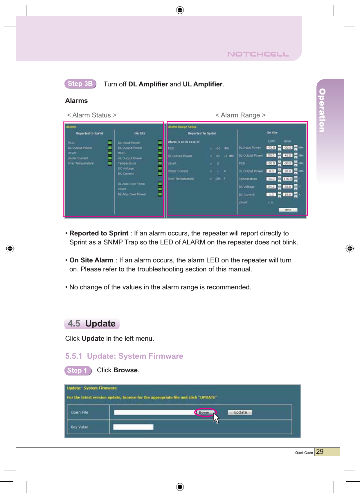
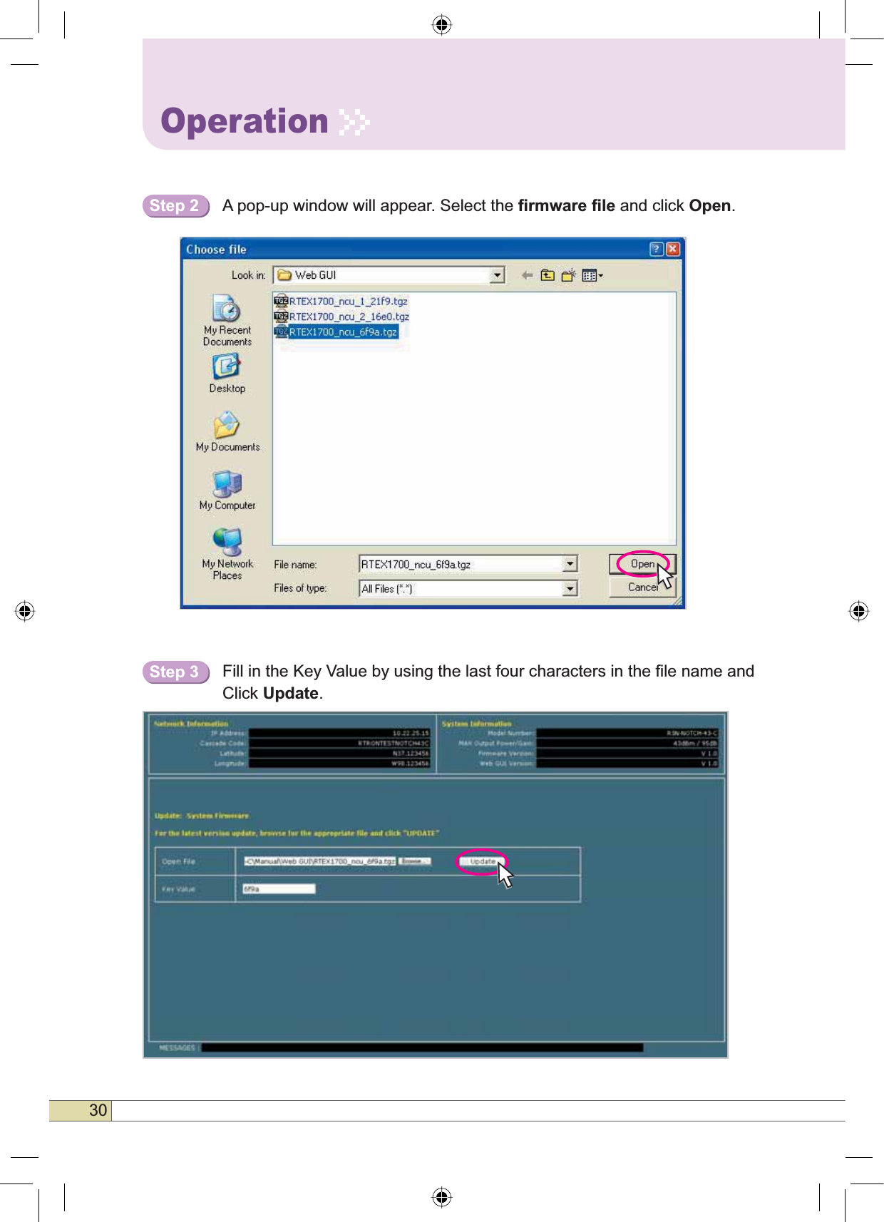
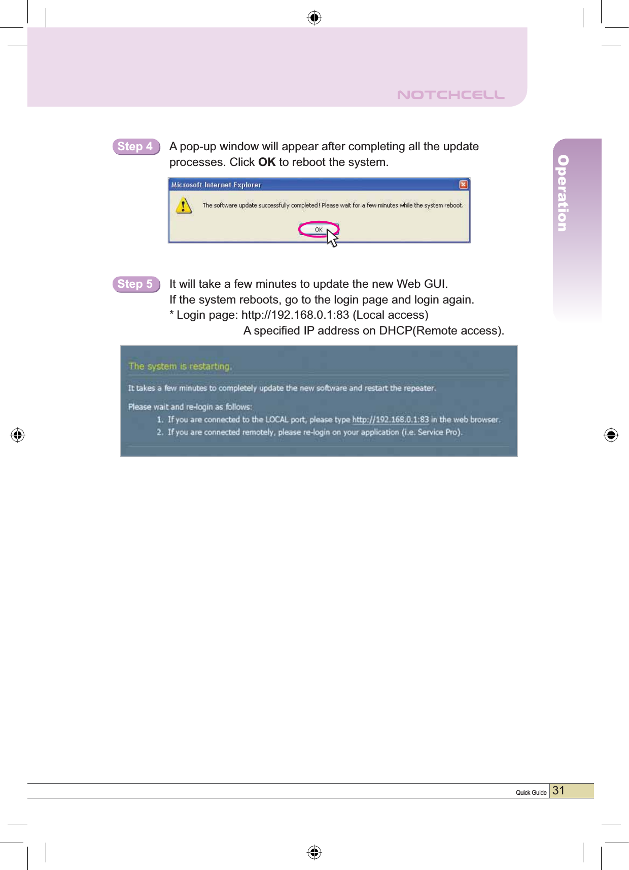
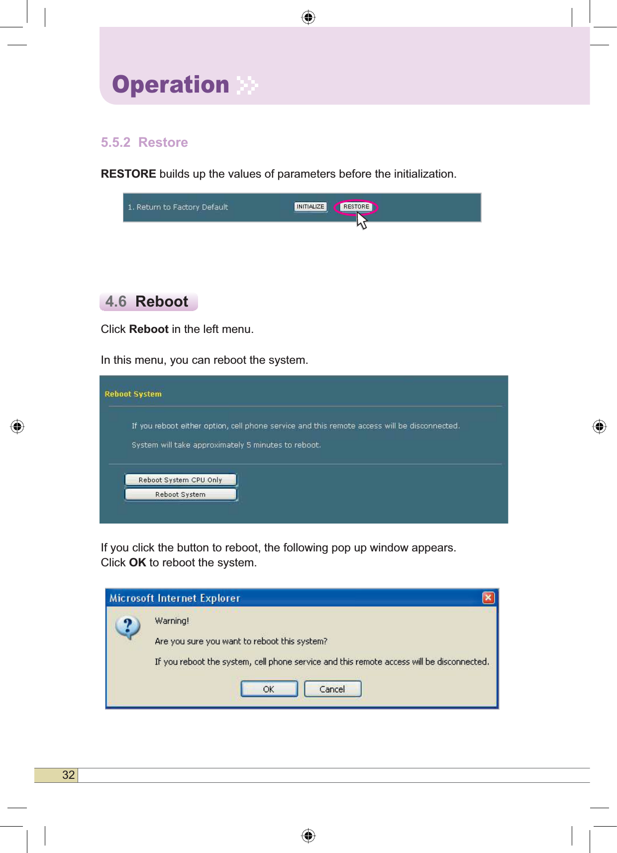
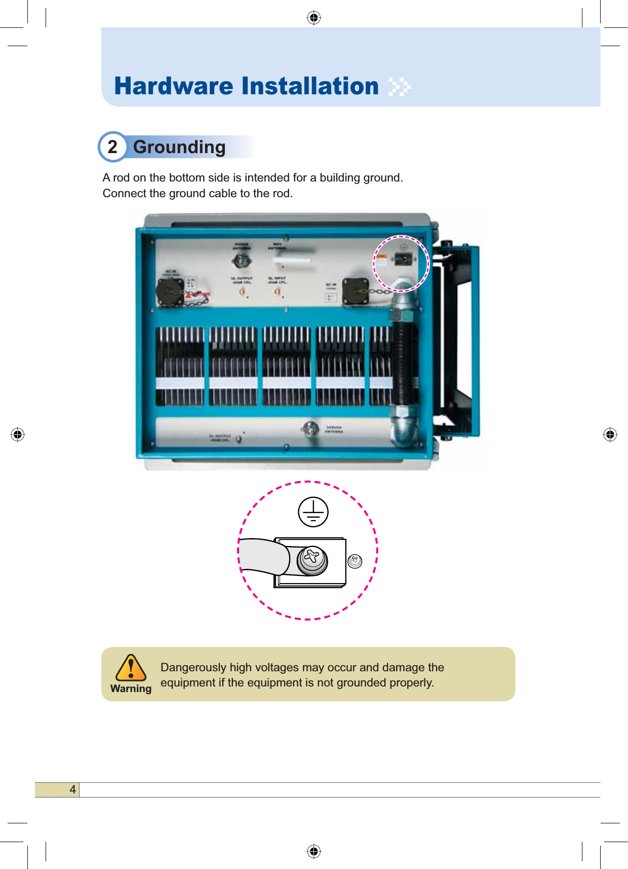
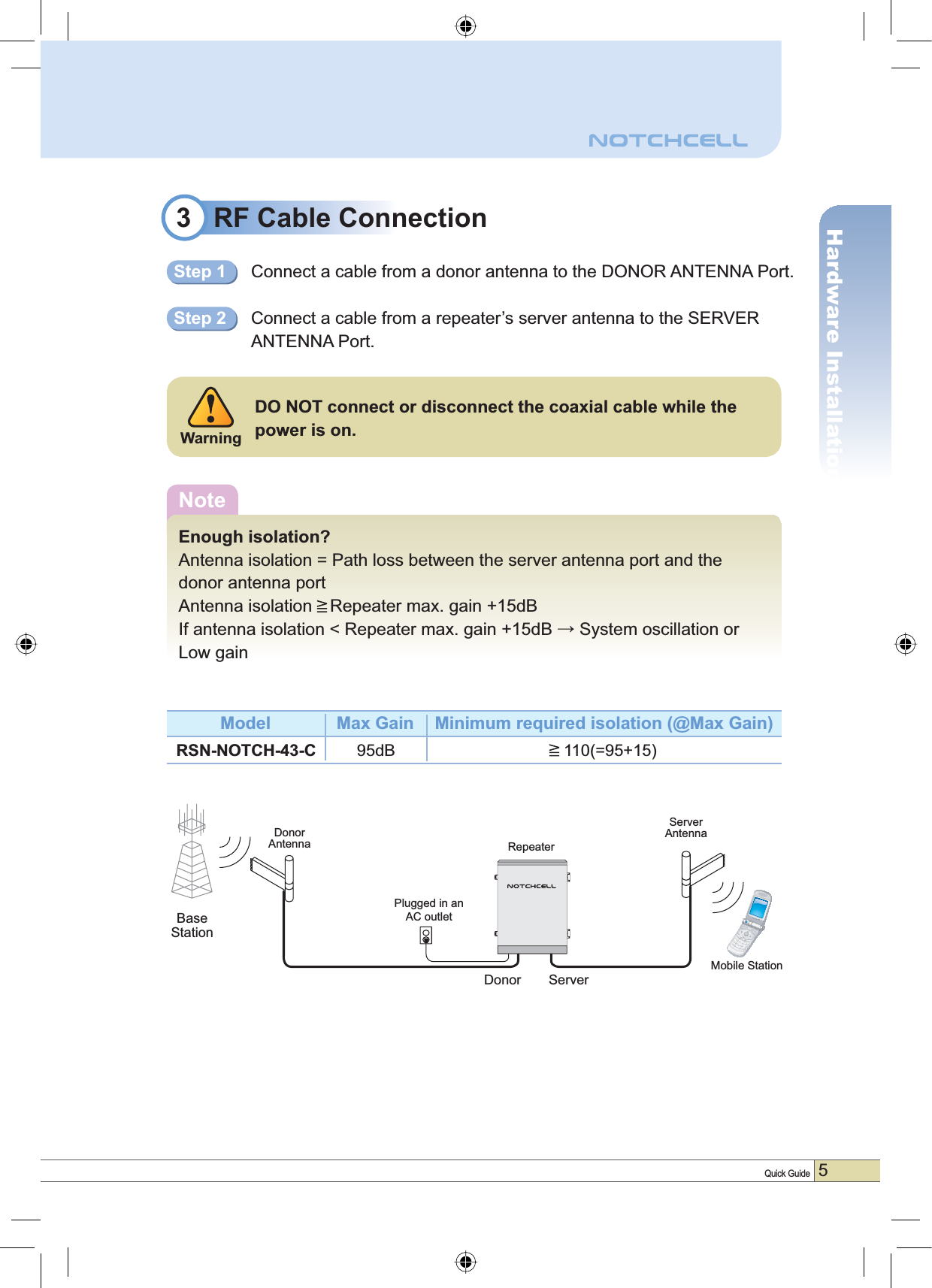
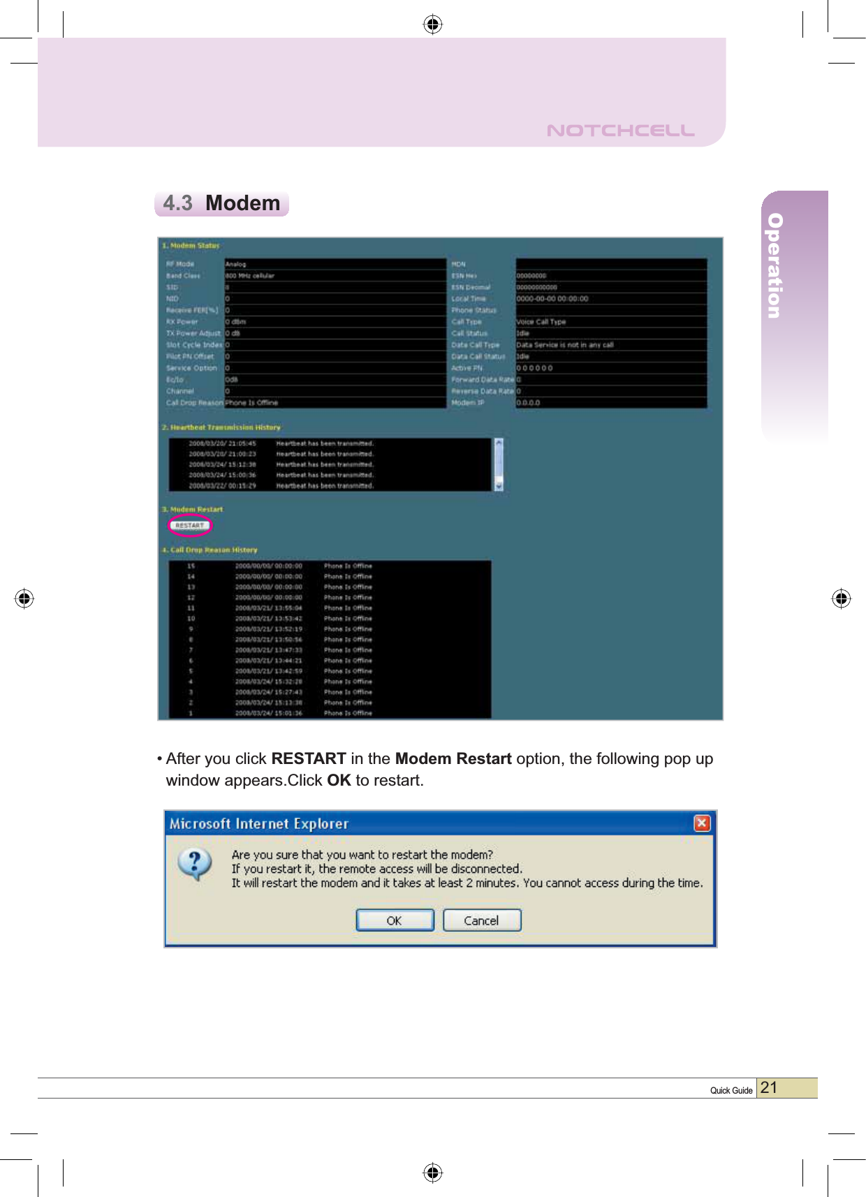
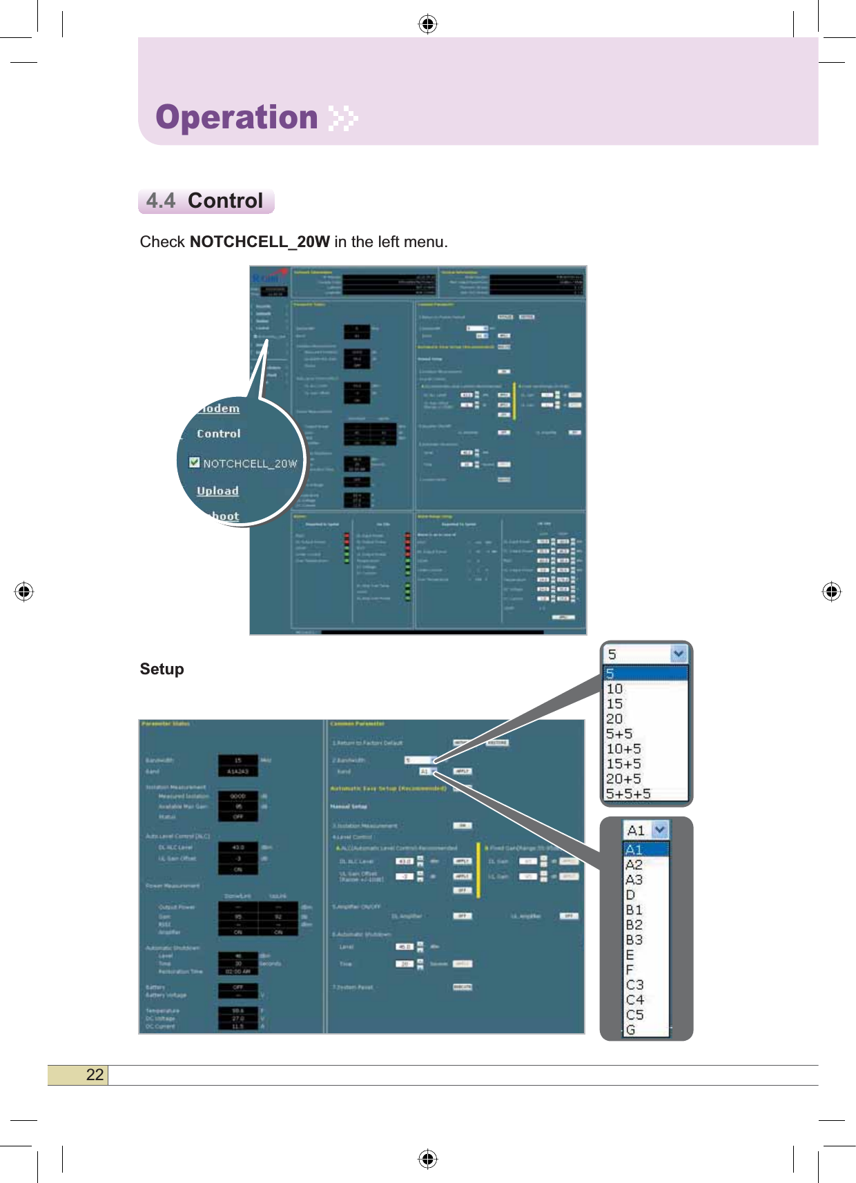
![1Quick GuideIntroductionIntroductionNOTCHCELL repeater can be used in CDMA service shaded areas likein-buildings, underground and tunnels to cover its service area. This repeater system designed for dual and simultaneous service, namely, it receives signals from the base station through donor antenna, amplifies the signals andre-transmits it to one or other mobile stations.- NOTCHCELL utilizes the web-based user interface and web server to support the remote access. There are two physical LAN ports: • The Local port provides the wireless on-site access to the repeater.The two ports allow local and remote users to access the repeater simultaneously. - DHCP server at the Local port enables Plug and Play by automatically assigning the IP address to the user’s computer.- Parameter setup is only one click away – • Automatic Easy Setup feature will measure the isolation and limit the maximum gain accordingly. This will also enable Auto Level Control as well as Auto Shut Down. These two features are strongly recommended to prevent the uncontrolled power output, which could have an adverse impact on the RF network and the repeater. For example, ALC will automatically apply attenuation when the input signal strength is increased due to the new base station deployment near the repeater site. • R-tron implemented intelligent design in the NOTCHCELL as following:ƇProgrammable Bandwidth and Band » 5, 10, 15, and 20 MHz contiguous and non-contiguous segments » Any Band Combination within 65MHz PCS Band [A,D,B,E,F,C,G] » Three (3) 5MHz segmentsƇRemote Access and ControlƇBuilt in CDMA MODEMƇ(DV\DQG4XLFN,QVWDOODWLRQª:HEEDVHG*8,» Plug and Play - DHCP Server @ Local Port » Automatic Easy Setup (Recommended) » ,VRODWLRQ'HWHFWLRQ » WiFi Access on siteƇAuto Level Control & Auto Shut DownNOTCH antenna (Sold separately)A NOTCH antenna has great front-back ratio and ensures the better isolation between the Donor Antenna and Server Antenna. It is optimized for the NOTCHCELL models.It is recommended to use the NOTCH antenna when installing the NOTCHCELL models.](https://usermanual.wiki/R-tron/SN-NOTCH-43-C/User-Guide-924204-Page-3.png)
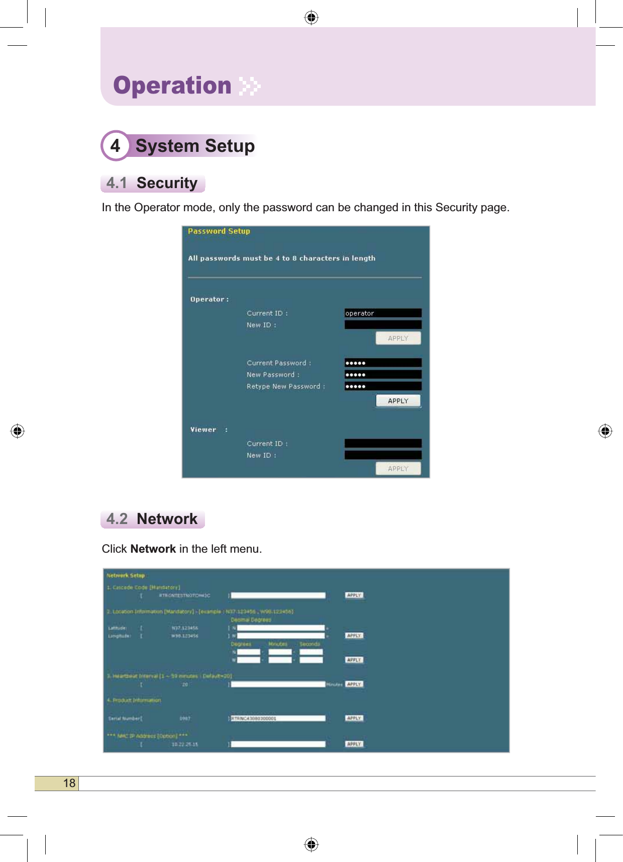
![19Quick GuideOperation1HWZRUN6HWXS•Cascade Code [Mandatory]: Type in the pre-assigned code. Otherwise,you cannot access system setup.•/RFDWLRQ,QIRUPDWLRQ: Enter the latitude and longitude of a location, otherwise you cannot access the system setup. You can input either Decimal Degrees or Degrees-Minutes-Seconds. [Example.](‘N/S ‘ | ‘E/W ‘) ddd.dddddd: (Latitude: N 39.006957 Longitude: W 94.532306)•+HDUWEHDW,QWHUYDO: Sets the time to transmit the Heartbeat to NMC Server.(Default value is 20 minutes. At the setup, temporarily reduce the value to 1minute. After conforming heartbeat report, set the value back to 20 minutes.)•3URGXFW,QIRUPDWLRQ: This is for manufacturer used only. DO NOT change this value.•6WDWLF,3IRU5HPRWH&RQWURO: Connect to the External Monitoring Device for Remote Access. Do not enter any value unless a static IP is assigned. DHCP client.•10&6HUYHU,3:Do not change this value; otherwise, the Heartbeat transmission or Remote Access may not work.](https://usermanual.wiki/R-tron/SN-NOTCH-43-C/User-Guide-924204-Page-21.png)
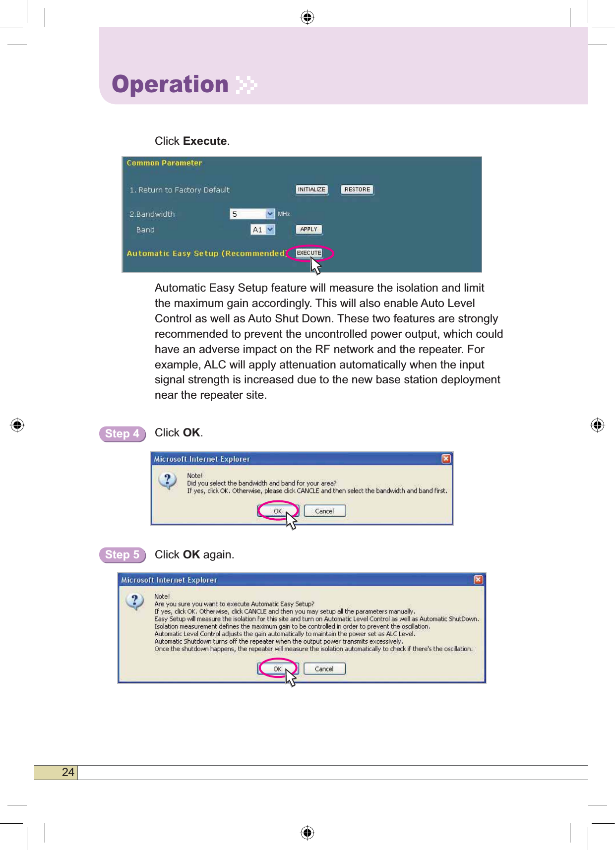
![23Quick GuideOperationSolution 1. Automatic Easy Setup (Recommended)Return To Factory DefaultsStep 1Select Bandwidth and Band and click APPLY.• To reset to factory defaults, click ,1,7,$/,=(.Automatic Easy Setup (Recommended)Automatic Easy Setup proceeds to:• Isolation measurement On • Calculation of Available Maximum Gain by the isolation.• ASD On• ALC On to get Maximum DL Output Power 43dBm [Default] or Maximum Gain 95dB.Step 2Step 3](https://usermanual.wiki/R-tron/SN-NOTCH-43-C/User-Guide-924204-Page-25.png)
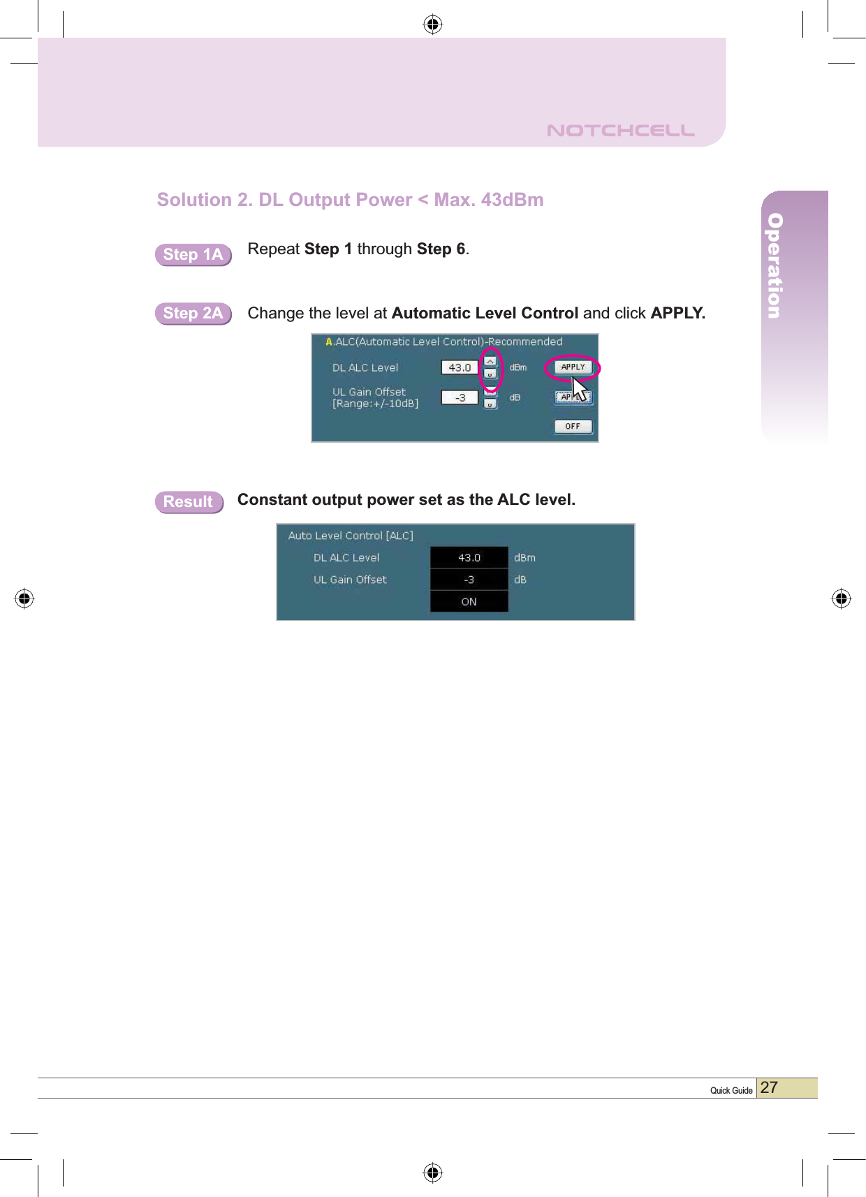
![25Quick GuideOperationSetup will automatically begin.Step 6NoteAutomatic Easy Setup process will take approximately 20 seconds.Constant Maximum DL Output Power 43dBmif DL Input Power >= -52dBm.Maximum Gain 85dB if DL Input Power < -52dBm.After running Automatic Easy Setup or ,VRODWLRQ0HDVXUHPHQW,,VRODWLRQvalue is displayed with “GOOD” when the isolation is higher than 110dB, or it is displayed with the actual value when the isolation is lower than 110dB.•Automatic Level Control: Type under 43 and then click APPLY and ON. [Example]For the repeater with 43dBm maximum output power, 95dB maximum JDLQG%JDLQFRQWUROUDQJHĺ,ILQSXWVLJQDOG%PDQG$/&LVVHWDV43dBm, the gain will be 88dB to adjust to the output power.If input signal is -60dBm, the output power will be 35dBm by the limitation of the maximum gain even though the ALC is set as 43dBm.Result 1Result 2](https://usermanual.wiki/R-tron/SN-NOTCH-43-C/User-Guide-924204-Page-27.png)
![26OperationTip$SSO\LQJ8SOLQN*DLQ2IIVHWPerform the following steps to adjust the Uplink Gain by the offset relative to the Downlink Gain.Downlink Gain Uplink GainUplink Gain Offset•Automatic Shutdown: Type the desired values for dBm,seconds, and then click APPLY. (e.g. 46dBm, 20seconds)[Example]For the repeater with 46dBm maximum output power, 95dB maximum gain / 40dB gain control range, Assuming ASD Level: 46dBm,ASD Time: 20seconds. If the output power is 46dBm (ASD LEVEL) and higher, the repeater will shutdown for 20 seconds (ASD TIME).RestorationRestoration recovers the service by turning on the amplifiers of repeater fundamentally. After a permanent shutdown, the Restoration turns on the amplifiers of the repeater at the Restoration Time everyday.](https://usermanual.wiki/R-tron/SN-NOTCH-43-C/User-Guide-924204-Page-28.png)
![28OperationSolution 3. Fixed Gain [Not Recommended]Automatic Easy Setup will calculate the Available Maximum Gain which defines the maximum gain to be setup.Repeat Step 1 through Step 6.Read DL Input Power and the gain controlled by Automatic Easy Setup.Step 1B Step 2B DO NOT setup the gain higher than the Available Maximum Gain.Warning](https://usermanual.wiki/R-tron/SN-NOTCH-43-C/User-Guide-924204-Page-30.png)