User manual

Quick Guide
Please read this manual before operating this product.
$IWHU\RX¿QLVKUHDGLQJWKLVPDQXDOVWRUHLWLQDVDIHSODFHIRUIXWXUHUHIHUHQFH
RSN-NOTCH-43-C

Address: R-tron Inc. 6402 College Boulevard, Overland Park, KS 66211
Phone: +1-913-344-9977, 1-888-31R-TRON
Fax: +1-913-344-9988
e-mail: info@r-tron.com
Website: www.r-tron.com

1
Quick Guide
Introduction
Introduction
NOTCHCELL repeater can be used in CDMA service shaded areas like
in-buildings, underground and tunnels to cover its service area. This repeater
system designed for dual and simultaneous service, namely, it receives signals from
the base station through donor antenna, amplifies the signals and
re-transmits it to one or other mobile stations.
- NOTCHCELL utilizes the web-based user interface and web server to support
the remote access. There are two physical LAN ports:
• The Local port provides the wireless on-site access to the repeater.
The two ports allow local and remote users to access the repeater
simultaneously.
- DHCP server at the Local port enables Plug and Play by automatically assigning
the IP address to the user’s computer.
- Parameter setup is only one click away –
• Automatic Easy Setup feature will measure the isolation and limit the maximum
gain accordingly. This will also enable Auto Level Control as well as Auto
Shut Down. These two features are strongly recommended to prevent the
uncontrolled power output, which could have an adverse impact on the
RF network and the repeater. For example, ALC will automatically apply
attenuation when the input signal strength is increased due to the new base
station deployment near the repeater site.
• R-tron implemented intelligent design in the NOTCHCELL as following:
Ƈ
Programmable Bandwidth and Band
»
5, 10, 15, and 20 MHz contiguous and non-contiguous segments
»
Any Band Combination within 65MHz PCS Band [A,D,B,E,F,C,G]
» Three (3) 5MHz segments
Ƈ
Remote Access and Control
Ƈ
Built in CDMA MODEM
Ƈ(DV\DQG4XLFN,QVWDOODWLRQ
ª:HEEDVHG*8,
» Plug and Play - DHCP Server @ Local Port
»
Automatic Easy Setup (Recommended)
»
,VRODWLRQ'HWHFWLRQ
»
WiFi Access on site
Ƈ
Auto Level Control & Auto Shut Down
NOTCH antenna (Sold separately)
A NOTCH antenna has great front-back ratio and ensures the better isolation
between the Donor Antenna and Server Antenna.
It is optimized for the NOTCHCELL models.
It is recommended to use the NOTCH antenna when installing the NOTCHCELL
models.

2
The installation procedure is as follows:
0RXQWLQJĺ*URXQGLQJĺ5)&RQQHFWLRQĺ3RZHU2Q
First of all, check list of items:
Repeater (1), AC Cord (1), Anchor Bolts (4), WiFi Antenna (1), UTP Cross LAN
Cable (1), Quick Guide (1), User’s Manual (1)
Hardware Installation
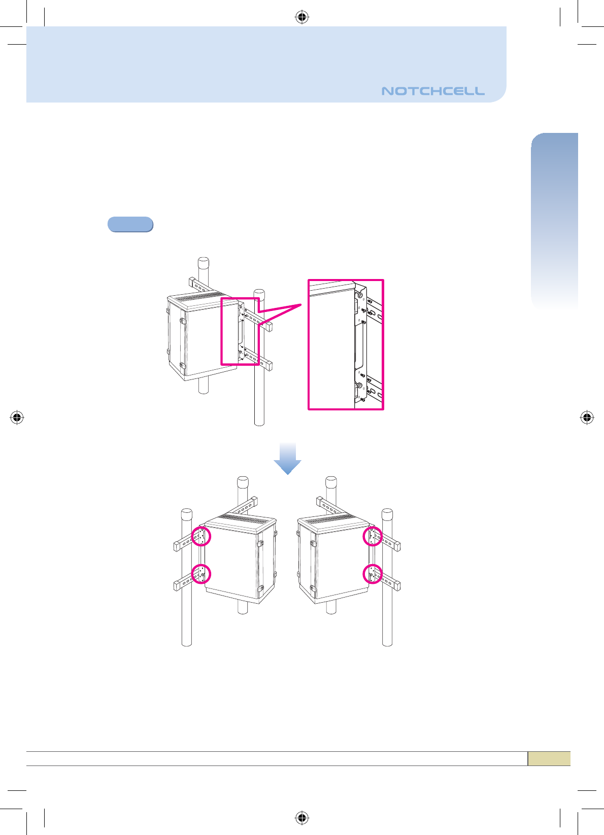
Fixate the mounting bracket onto the structure using provided bolts
or extra screws.
2Mounting
Step 1
Lean the NOTCHCELL to hang the topside of the Guide Ring on the
mounting bracket, and push towards the structure to mount.
Step 2
3
Quick Guide
Hardware Installation
Fix the NOTCHCELL using 16 screws provided.
Step 3
4
Hardware Installation
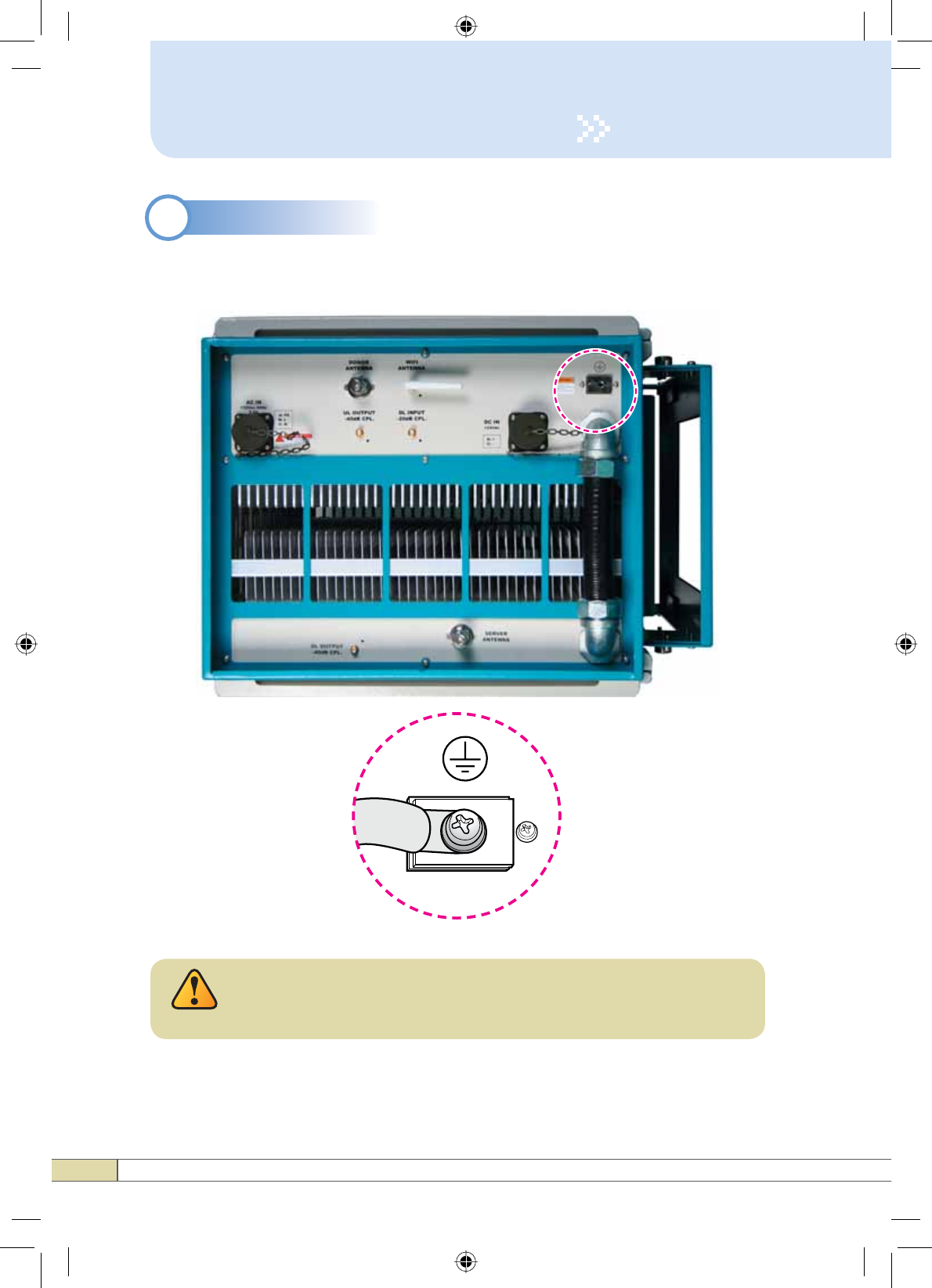
A rod on the bottom side is intended for a building ground.
Connect the ground cable to the rod.
2Grounding
Dangerously high voltages may occur and damage the
equipment if the equipment is not grounded properly.
Warning
5
Quick Guide
Hardware Installation
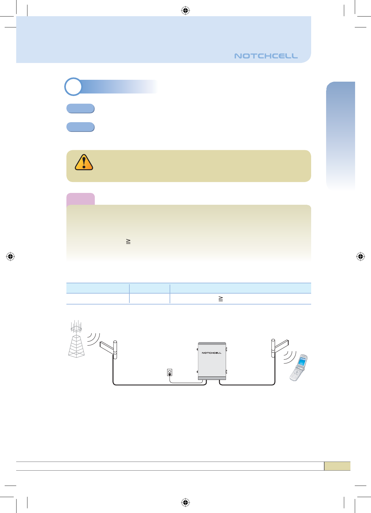
3RF Cable Connection
Connect a cable from a donor antenna to the DONOR ANTENNA Port.
Connect a cable from a repeater’s server antenna to the SERVER
ANTENNA Port.
Step 2
Step 1
Note
Enough isolation?
Antenna isolation = Path loss between the server antenna port and the
donor antenna port
Antenna isolation Repeater max. gain +15dB
If antenna isolation < Repeater max. gain +15dB ĺ System oscillation or
Low gain
Model Max Gain
95dBRSN-NOTCH-43-C
Minimum required isolation (@Max Gain)
110(=95+15)
DO NOT connect or disconnect the coaxial cable while the
power is on.
Warning
Repeater
Donor
Antenna
Plugged in an
AC outlet
Donor
Base
Station
Server
Mobile Station
Server
Antenna
Hardware Installation
6
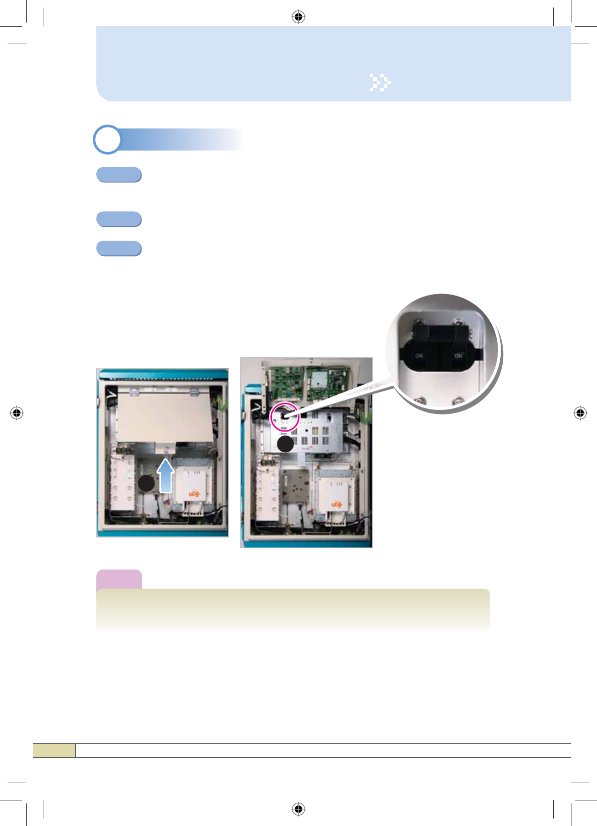
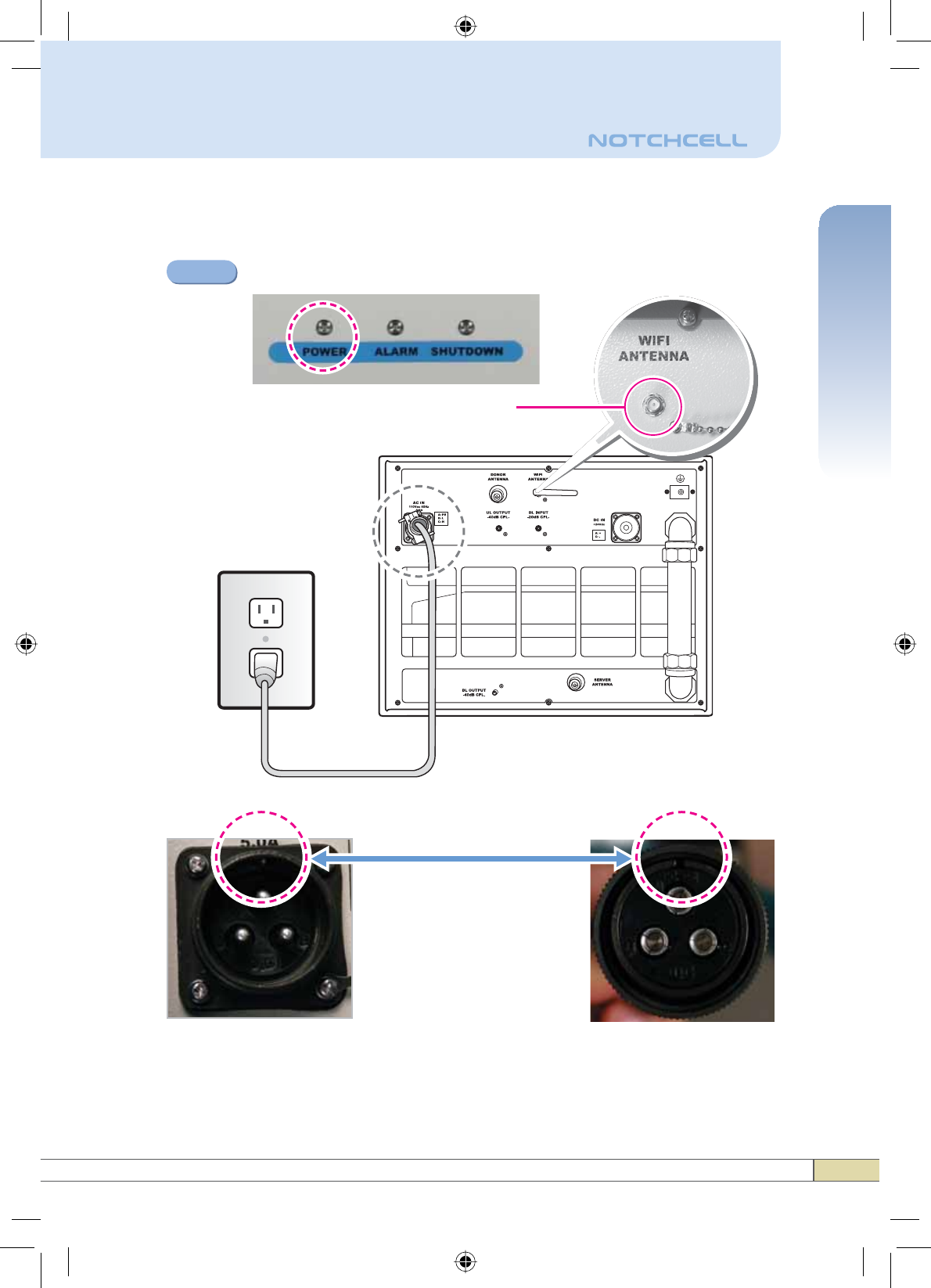
4Power On
Connect the power cord.
Align the grooves fit into each other before connecting the power cord.
Plug the power cord into a wall outlet.
Power Switch turns on.
Step 1
Step 2
Step 3
Note
It will take approximately 1 minute to boot after turning it on.
Attach the WiFi Antenna before turning on the power.
How to turn on the power switch
2
1
7
Quick Guide
Hardware Installation
※ Match the each groove when connecting the power cord.
Check if the Power LED turns on.
Attach the WIFI Antenna as shown.
Connecting the grooves
Step 4

8
1System Requirements
Operation
2.1 Windows XP
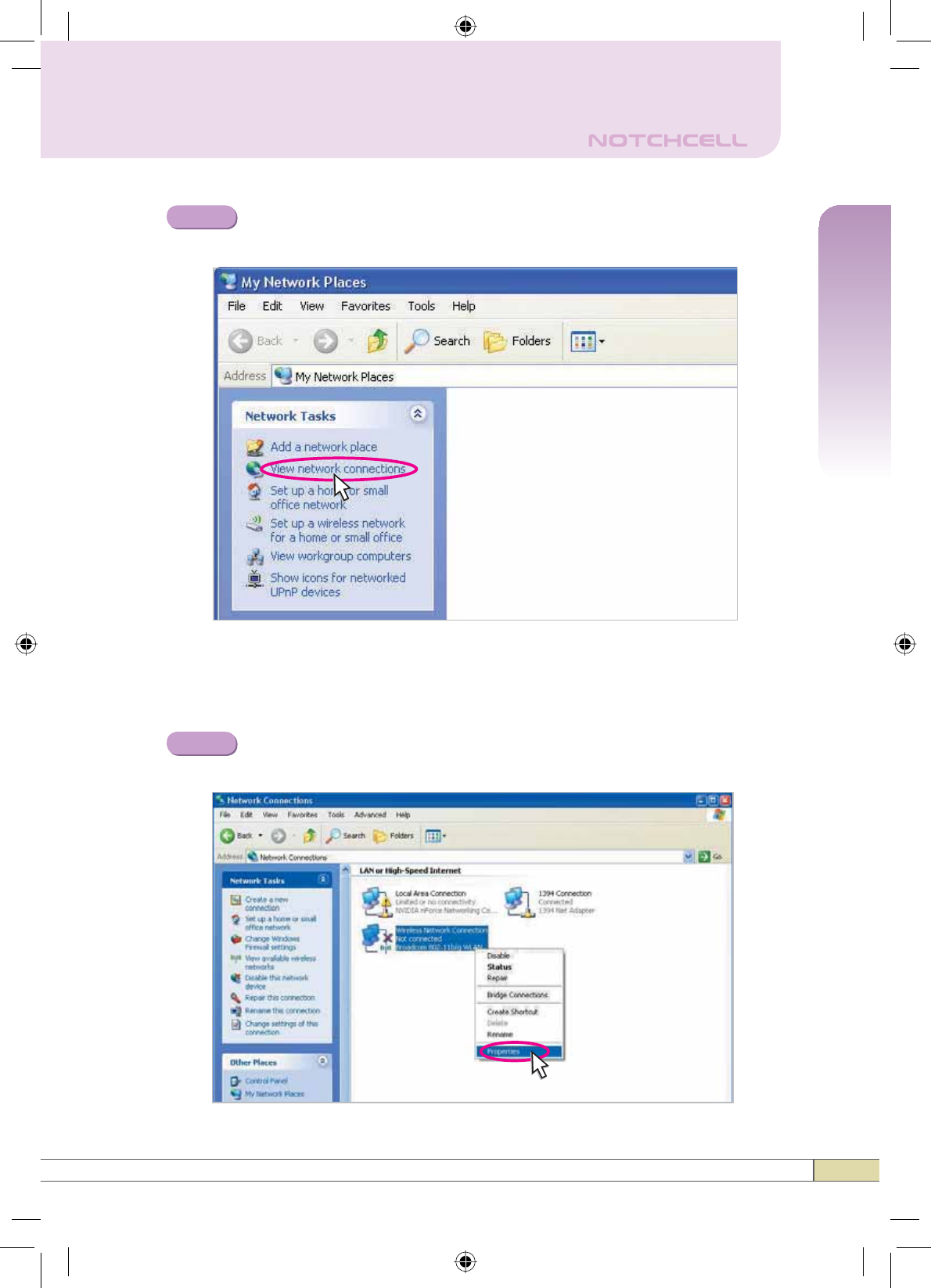
Click the Start button and 0\1HWZRUN3ODFHV.
Step 1
NOTCHCELL operates on a customer provided PC based platform with the
following system requirements:
• Windows® 2000, Windows® XP or Windows® Vista
• Internet Explorer 6.0 (Recommended) or higher
• 128 MB RAM or higher
• Pentium Ⅲ processor or higher
• RJ-45 jack required
21HWZRUN6HWXS
9
Quick Guide
Operation
Click 9LHZQHWZRUNFRQQHFWLRQV.
Step 2
Right-click Local Area Connection to see a shortcut menu and
click Properties.
Step 3
To use the wireless network connection, precede the “Step 3” shown in
the following and then go to the next Steps.
10
Operation
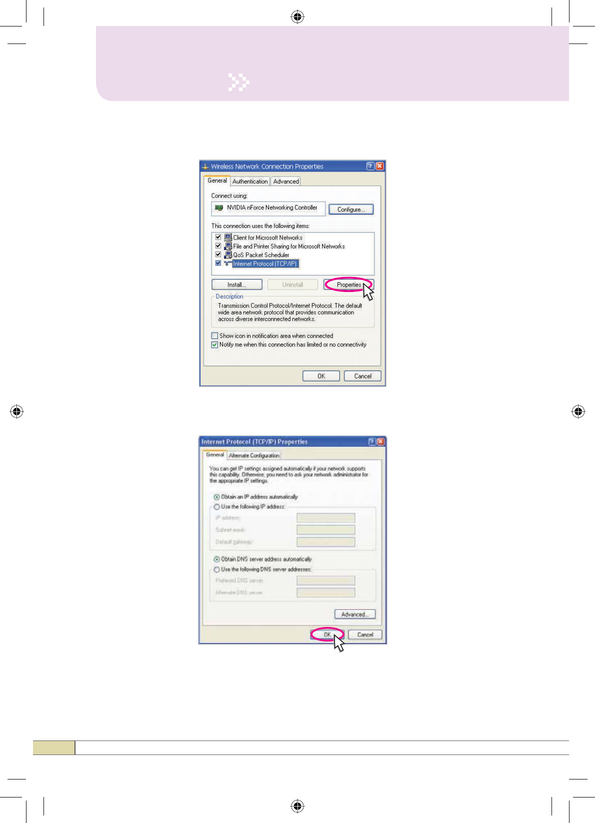
1) Select,QWHUQHW3URWRFRO7&3,3 and click Properties.
2) Check 2EWDLQDQ,3DGGUHVVDXWRPDWLFDOO\ and click OK.
11
Quick Guide
Operation
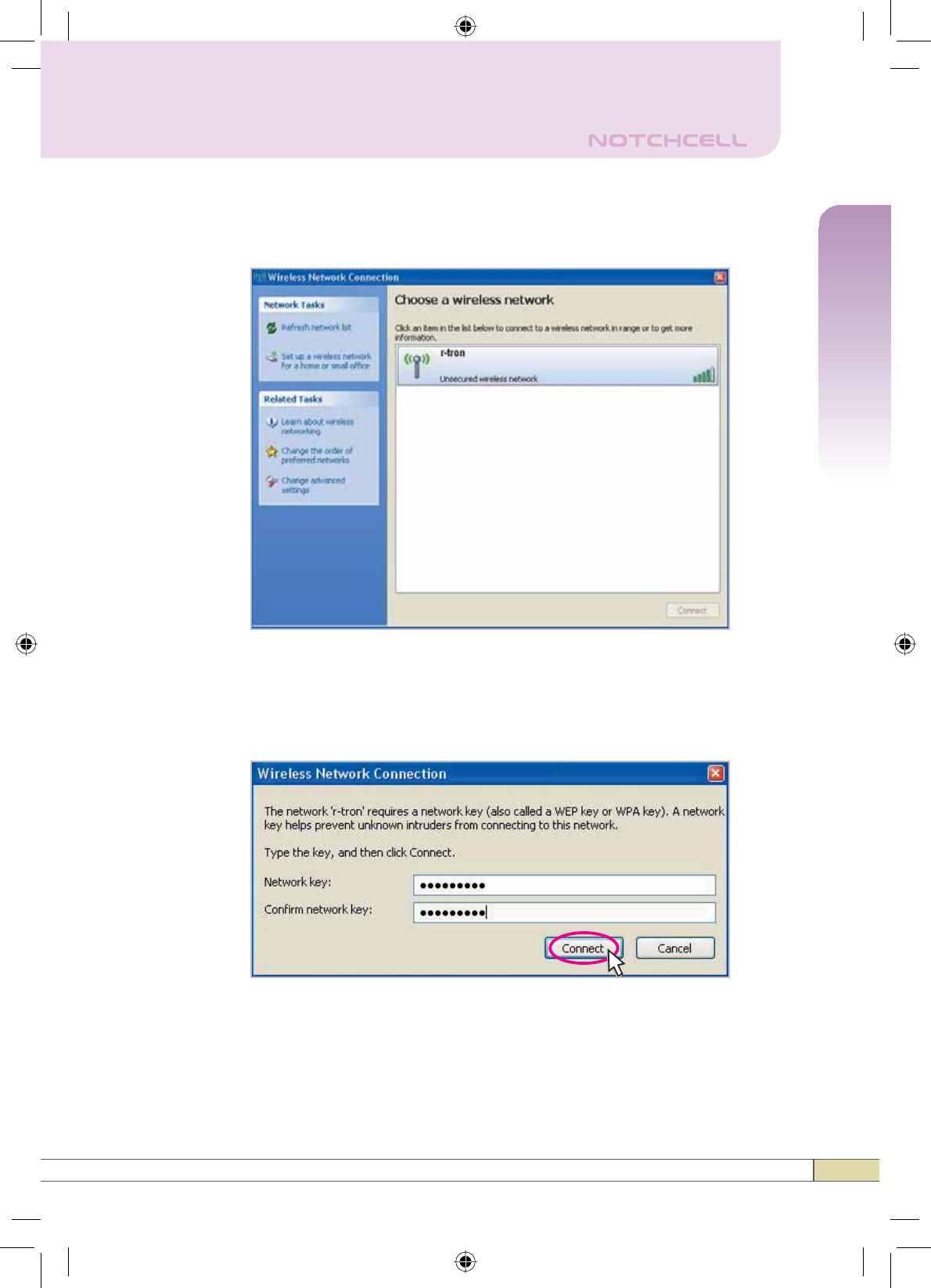
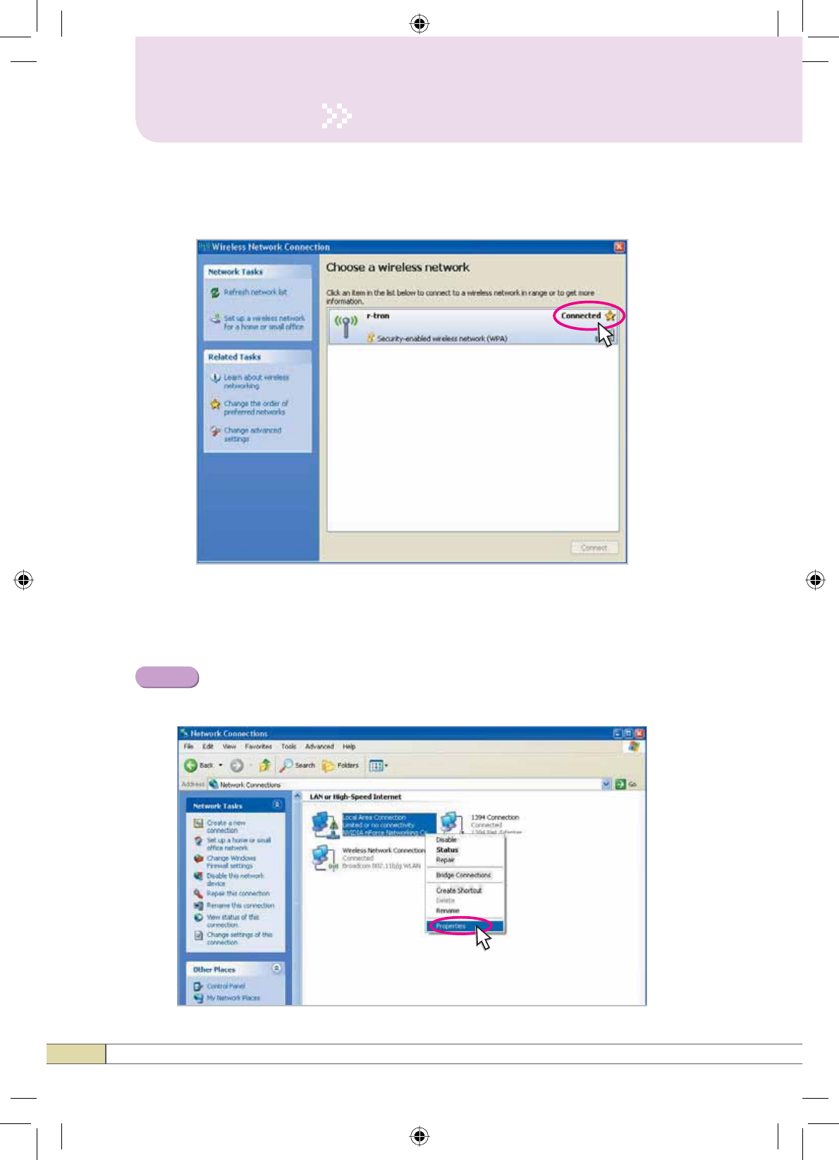
3) Click 9LHZDYDLODEOHZLUHOHVVQHWZRUNV and then the following
screen appears.
4) Double click r-tron and then you will be asked for the network key.
Type the network key, “notchcell” and click Connect.
12
Operation
5) Your wireless network connection has been completed if you see
the Connected as in the following screen.
Right-click Local area Connection to see a shortcut menu and click
Properties.
Step 3
To use the local area network connection, repeat the “Step 1 and 2” in the
page 8 and then go to the next Steps.
13
Quick Guide
Operation
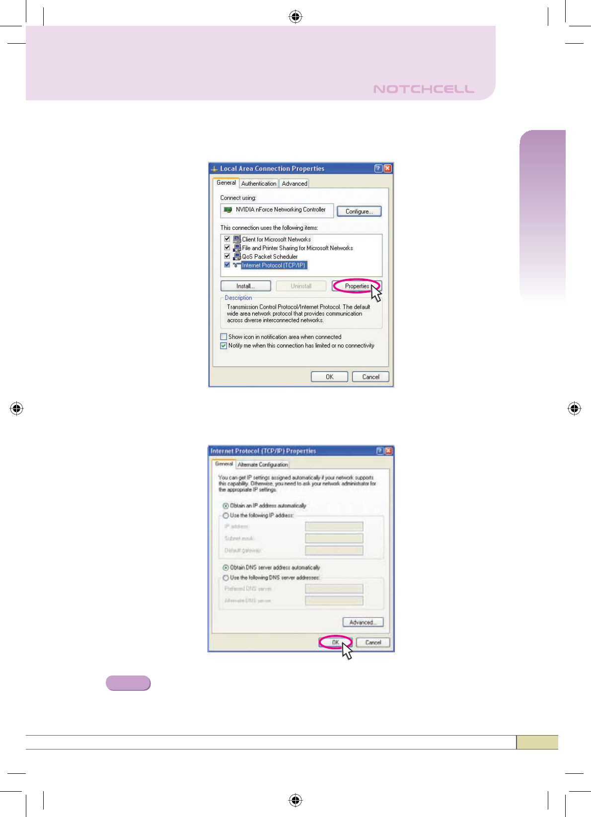
1) Select,QWHUQHW3URWRFRO7&3,3 and click Properties.
2) Check 2EWDLQDQ,3DGGUHVVDXWRPDWLFDOO\ and click OK.
Close all windows.
Step 4
14
Operation
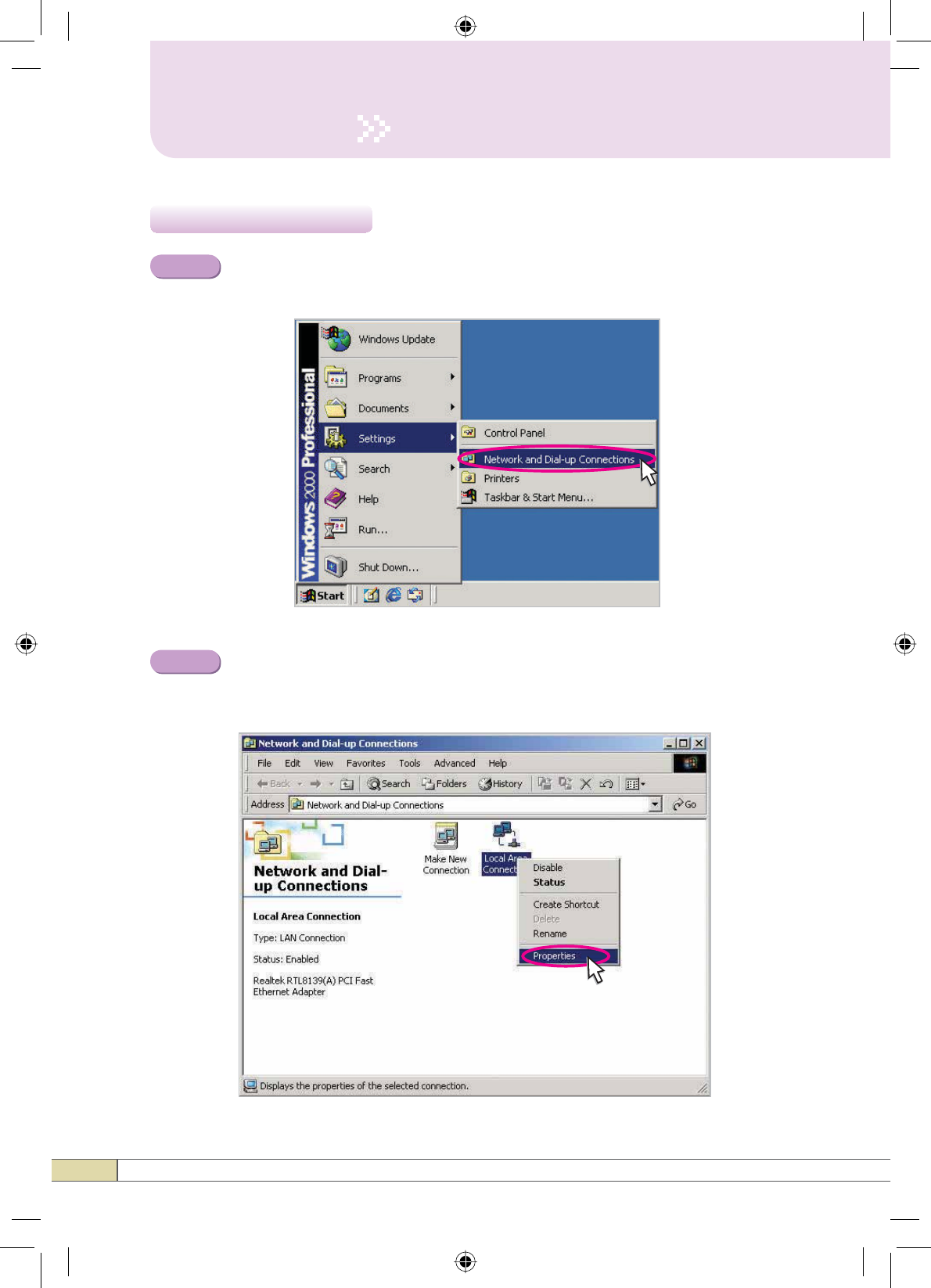
2.2 Windows 2000
Click the Start button, point to Settings, and then click 1HWZRUNDQG
Dial-up Connections.
Step 1
Right-click Local Area Connection to see a shortcut menu and
click Properties. Wireless network connection is available for the
Windows 2000 if connected to the network card(Sold separatly).
Step 2
15
Quick Guide
Operation
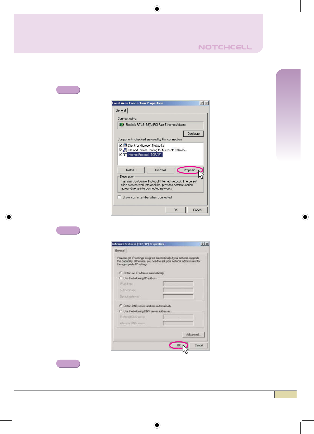
Select ,QWHUQHW3URWRFRO7&3,3 and click Properties.
Check 2EWDLQDQ,3DGGUHVVDXWRPDWLFDOO\ and click OK.
Close all windows.
Step 3
Step 4
Step 5
16
2.3 Windows Vista
Operation
Click the Start button and Control Panel.
Click 1HWZRUNDQG,QWHUQHW.
Click 1HWZRUNDQG6KDULQJ&HQWHU.
Step 2
Step 1
Step 3
Click &RQQHFWWRDQHWZRUN in the following screen.
1) Double click r-tron as shown in the following screen.
2) You will be asked for the network key. Input the network key,
“notchcell” in the following screen.
3) &RQQHFWWRDQHWZRUN screen appears.
4) Click View status of Wireless Network Connection.
Step 4
To use the wireless network connection, precede the “Step 4” shown in
the following and then go to the next Steps.
Step 5
Step 4
Step 6
Step 7
Step 8
To use the local area network connection, repeat the Step 1,2, 3 and then
go to the next Steps.
Click View status of Local Area Connection.
Click Properties and a caution pop-up window will appear.
Click OK.
Select ,QWHUQHW3URWRFRO9HUVLRQ7&3,3Y and click
Properties.
Check 2EWDLQDQ,3DGGUHVVDXWRPDWLFDOO\ and click OK.
Close all windows.
17
Quick Guide
Operation
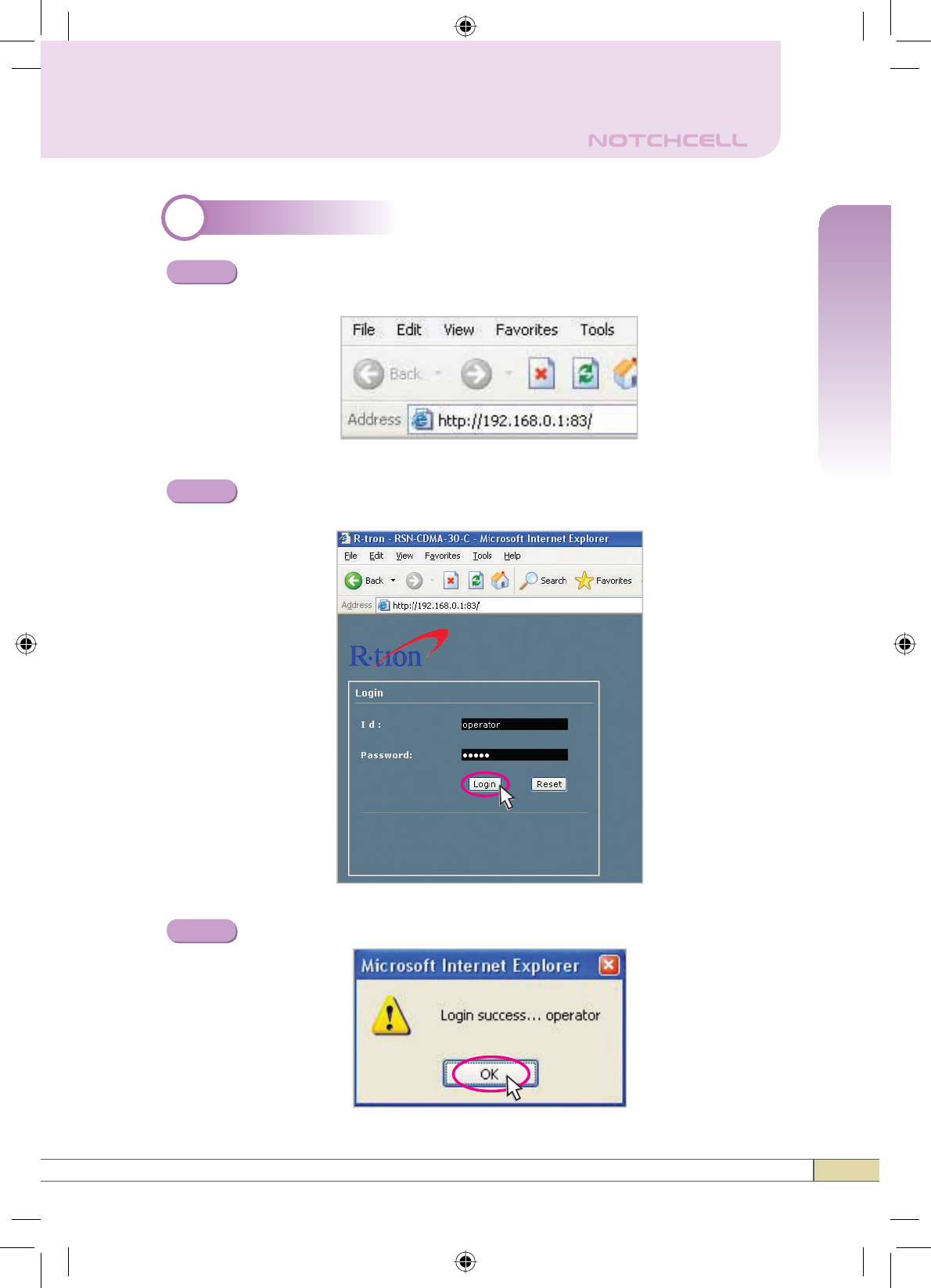
3System Login
Open your Web browser and type “192.168.0.1:83” into the URL
address box. Then press the Enter key.
Step 1
The login screen will appear. Type “operator” for the ID and
“rtron” for the password and then click OK.
The pop-up message for the login success will appear. Click OK.
Step 2
Step 3
18
Operation
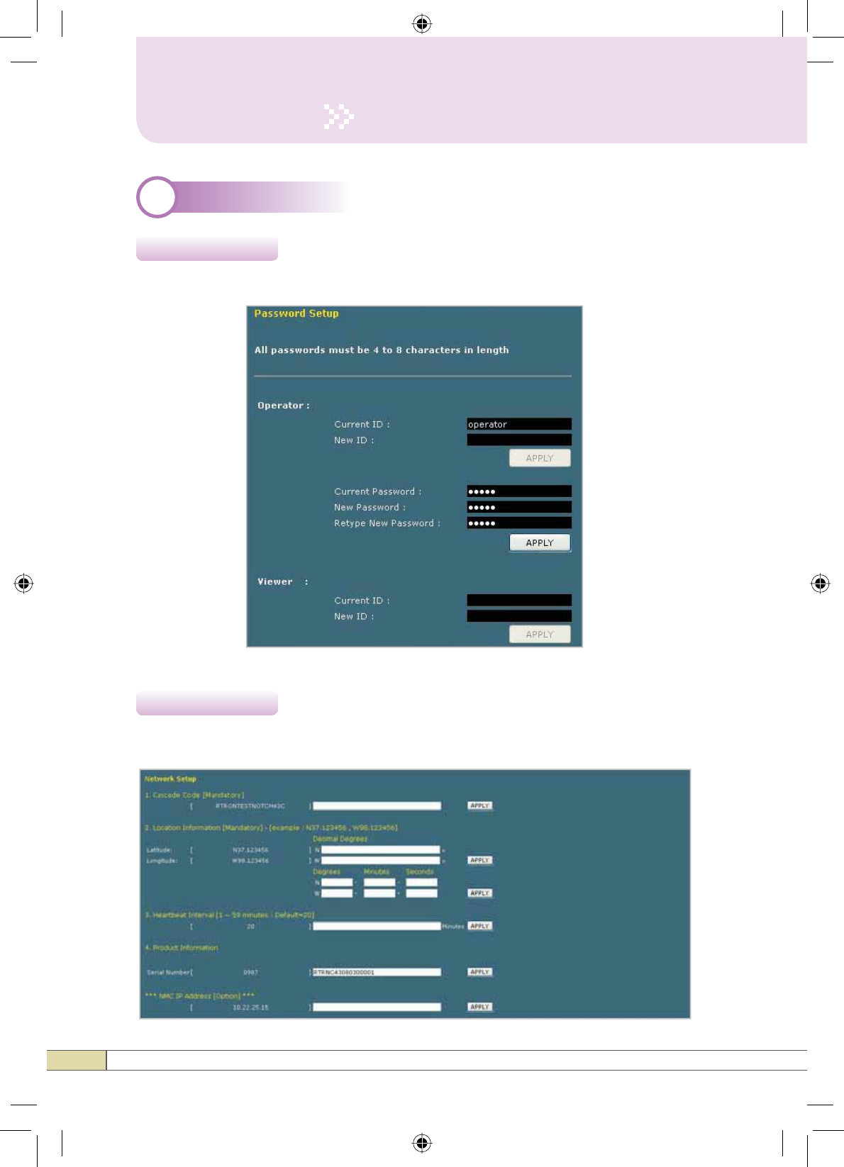
4System Setup
4.1 Security
In the Operator mode, only the password can be changed in this Security page.
Click 1HWZRUN in the left menu.
4.21HWZRUN
19
Quick Guide
Operation
1HWZRUN6HWXS
•Cascade Code [Mandatory]: Type in the pre-assigned code. Otherwise,
you cannot access system setup.
•/RFDWLRQ,QIRUPDWLRQ: Enter the latitude and longitude of a location,
otherwise you cannot access the system setup. You can input either Decimal
Degrees or Degrees-Minutes-Seconds.
[Example.]
(‘N/S ‘ | ‘E/W ‘) ddd.dddddd: (Latitude: N 39.006957 Longitude: W
94.532306)
•+HDUWEHDW,QWHUYDO: Sets the time to transmit the Heartbeat to NMC Server.
(Default value is 20 minutes. At the setup, temporarily reduce the value to 1
minute. After conforming heartbeat report, set the value back to 20 minutes.)
•3URGXFW,QIRUPDWLRQ: This is for manufacturer used only. DO NOT change
this value.
•6WDWLF,3IRU5HPRWH&RQWURO: Connect to the External Monitoring Device for
Remote Access. Do not enter any value unless a static IP is assigned. DHCP
client.
•10&6HUYHU,3:Do not change this value; otherwise, the Heartbeat
transmission or Remote Access may not work.
20
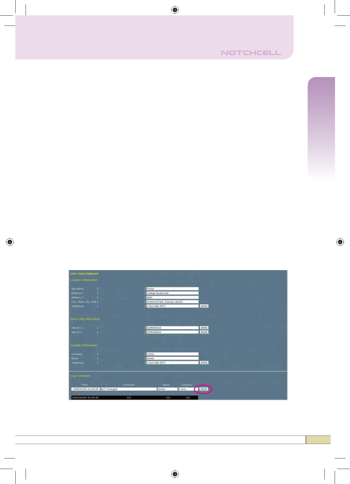
Operation
User Note
•/RFDWLRQ,QIRUPDWLRQ: Type the location information such as the building
name, address, city, state, zip code and telephone, and then click SAVE to
save the information you provide.
•'RQRU6LWH,QIRUPDWLRQ: Type the base station’s ID, and then click SAVE to
save the information you provide.
•,QVWDOOHU,QIRUPDWLRQ: Type the installer information such as the company,
name and telephone, and then click SAVE to save the information you
provide.
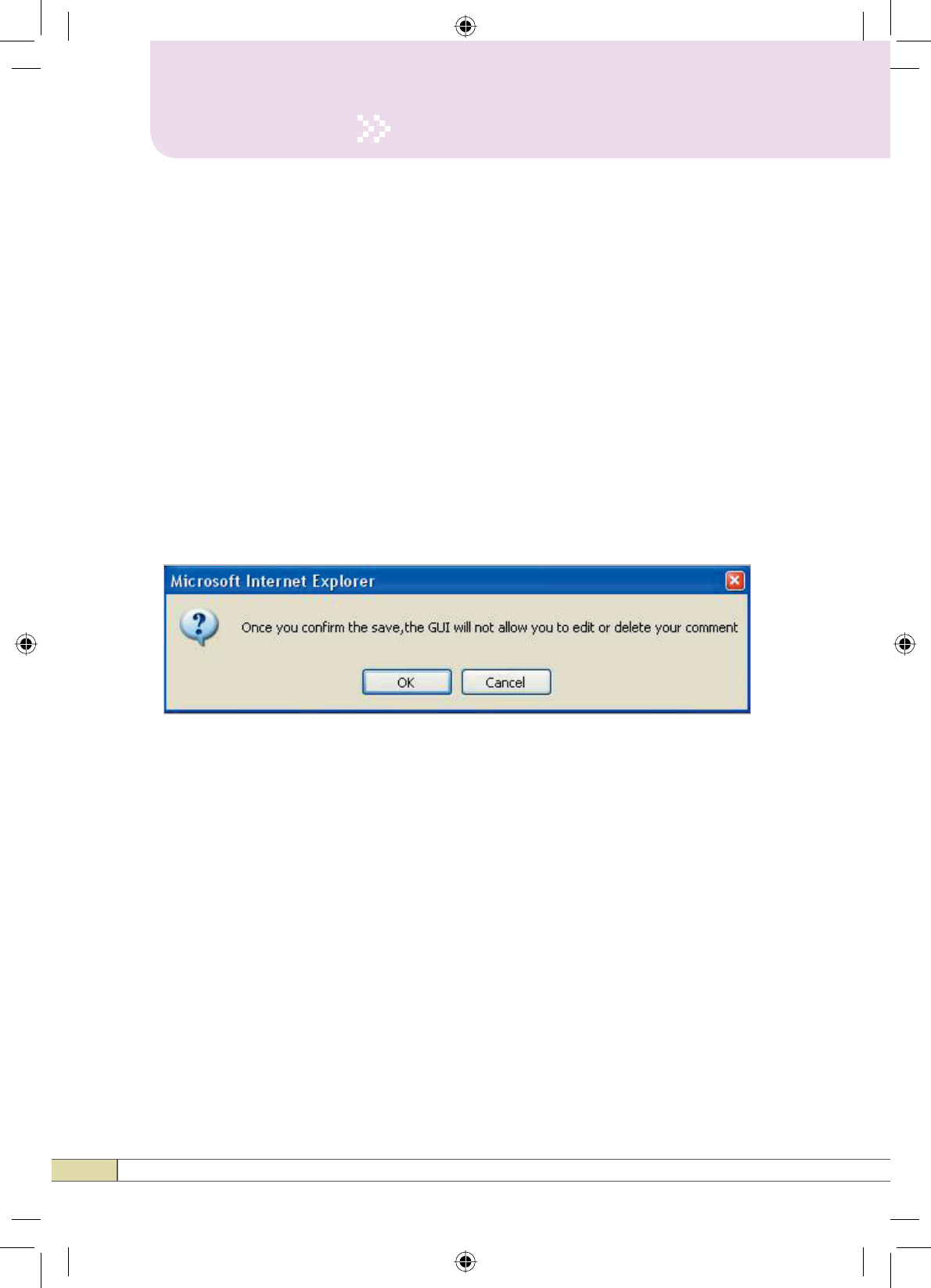
•User Comment: You can add comments. Up to 50 comments can be stored
in the memory. The length of characters for each comment is limited to 60
characters.
- After you click SAVE in the User Comment option, the following pop up
window appears. Click OK to save.
21
Quick Guide
Operation
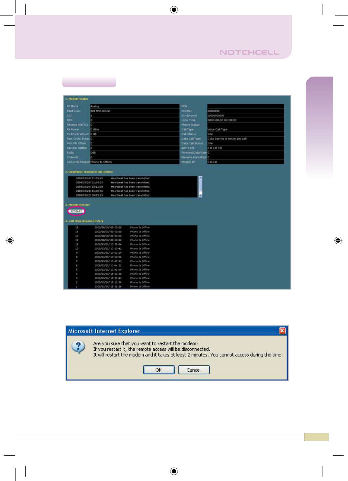
4.3 Modem
• After you click RESTART in the Modem Restart option, the following pop up
window appears.Click OK to restart.
22
Operation
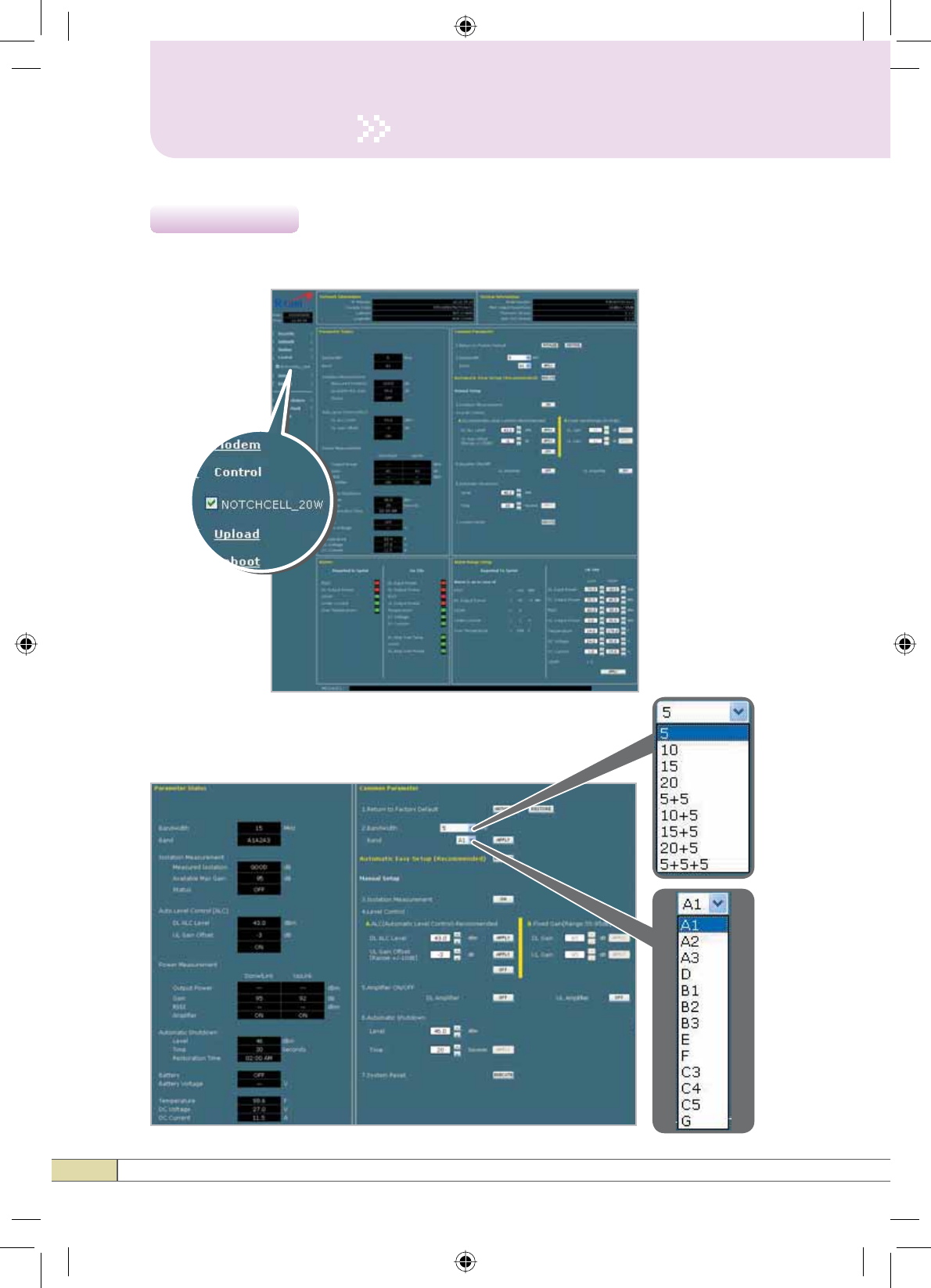
Check NOTCHCELL_20W in the left menu.
4.4 Control
Setup
23
Quick Guide
Operation
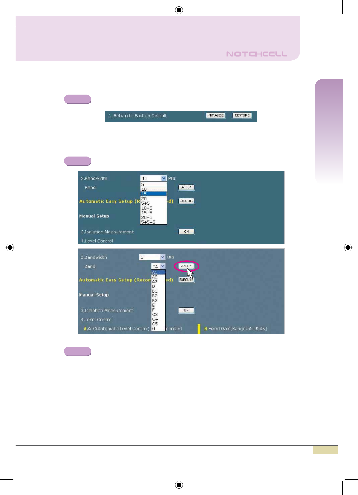
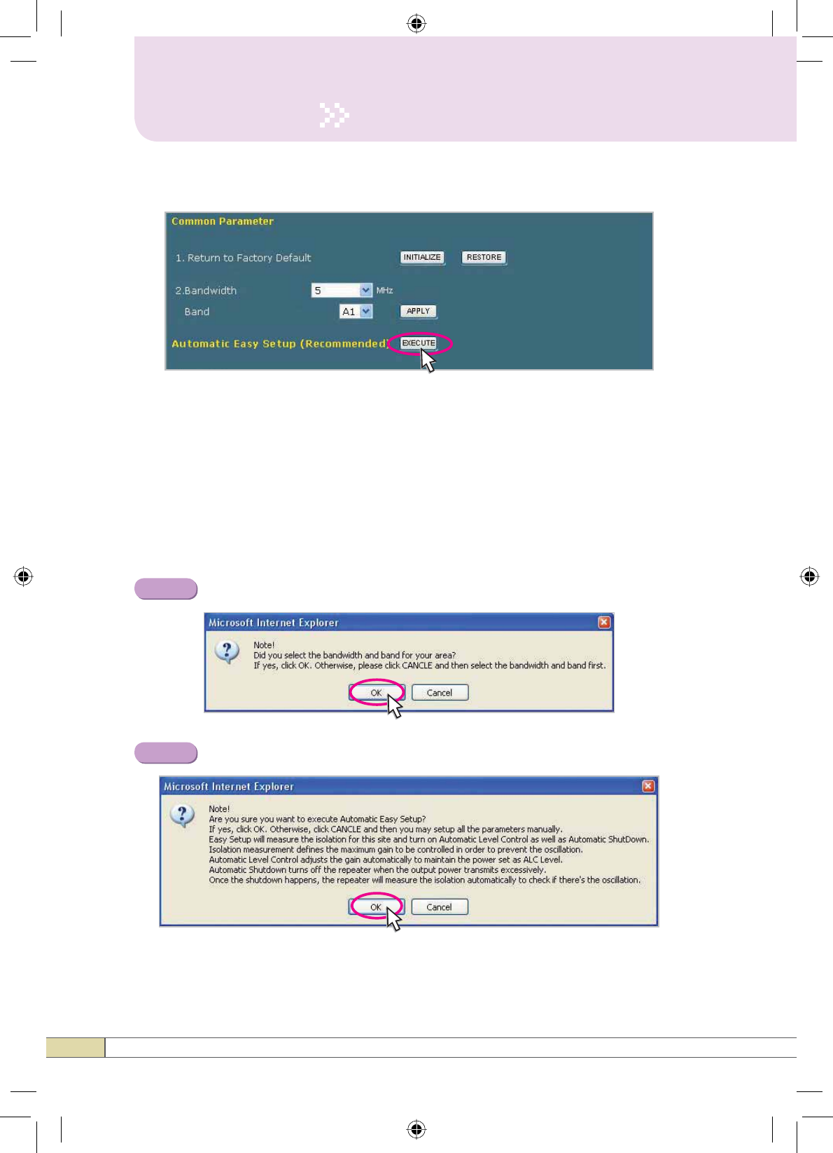
Solution 1. Automatic Easy Setup (Recommended)
Return To Factory Defaults
Step 1
Select Bandwidth and Band and click APPLY.
• To reset to factory defaults, click ,1,7,$/,=(.
Automatic Easy Setup (Recommended)
Automatic Easy Setup proceeds to:
• Isolation measurement On
• Calculation of Available Maximum Gain by the isolation.
• ASD On
• ALC On to get Maximum DL Output Power 43dBm [Default] or
Maximum Gain 95dB.
Step 2
Step 3
24
Operation
Click Execute.
Automatic Easy Setup feature will measure the isolation and limit
the maximum gain accordingly. This will also enable Auto Level
Control as well as Auto Shut Down. These two features are strongly
recommended to prevent the uncontrolled power output, which could
have an adverse impact on the RF network and the repeater. For
example, ALC will apply attenuation automatically when the input
signal strength is increased due to the new base station deployment
near the repeater site.
Click OK.
Click OK again.
Step 4
Step 5
25
Quick Guide
Operation
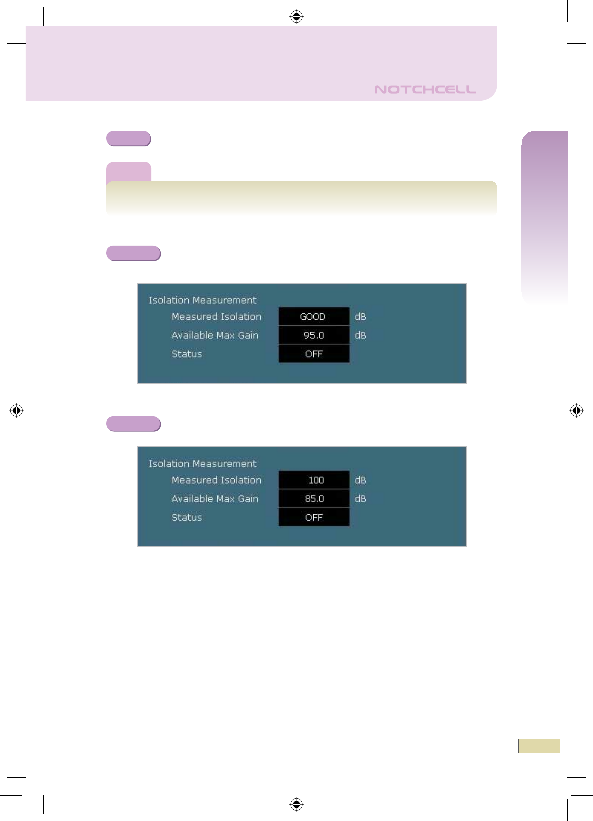
Setup will automatically begin.
Step 6
Note
Automatic Easy Setup process will take approximately 20 seconds.
Constant Maximum DL Output Power 43dBm
if DL Input Power >= -52dBm.
Maximum Gain 85dB if DL Input Power < -52dBm.
After running Automatic Easy Setup or ,VRODWLRQ0HDVXUHPHQW,,VRODWLRQ
value is displayed with “GOOD” when the isolation is higher than 110dB, or it is
displayed with the actual value when the isolation is lower than 110dB.
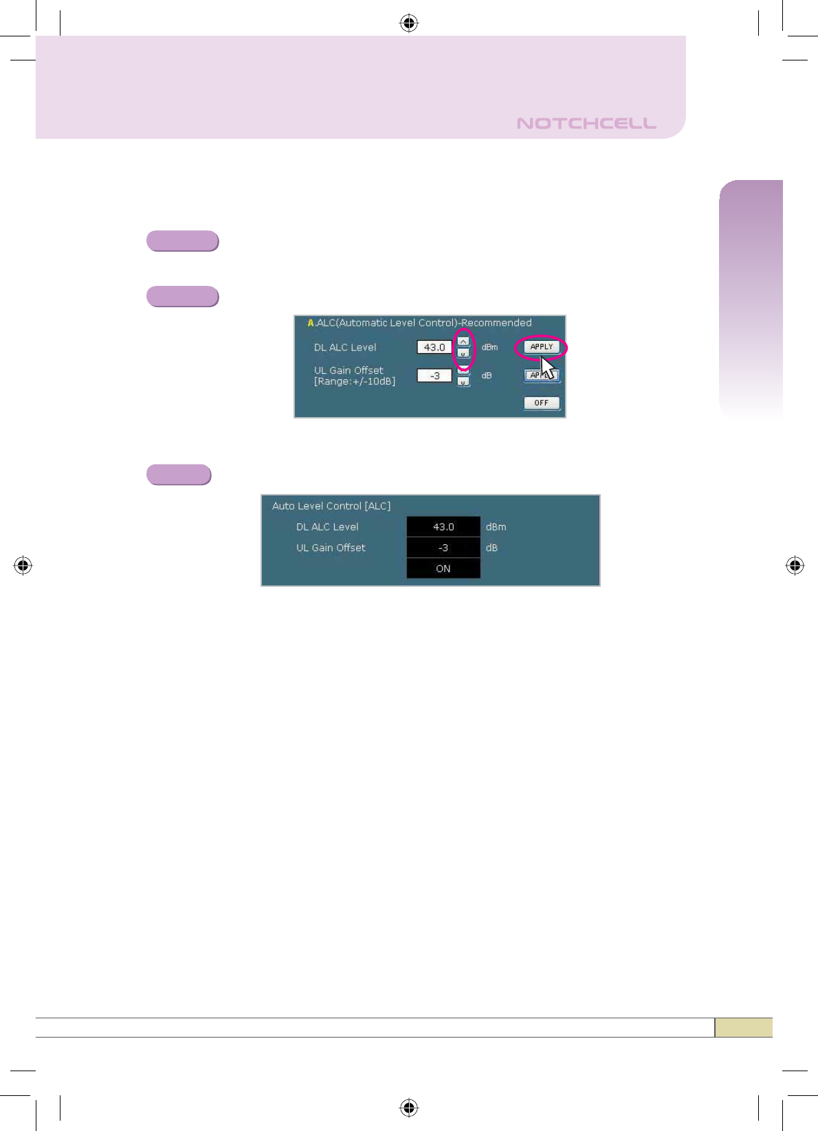
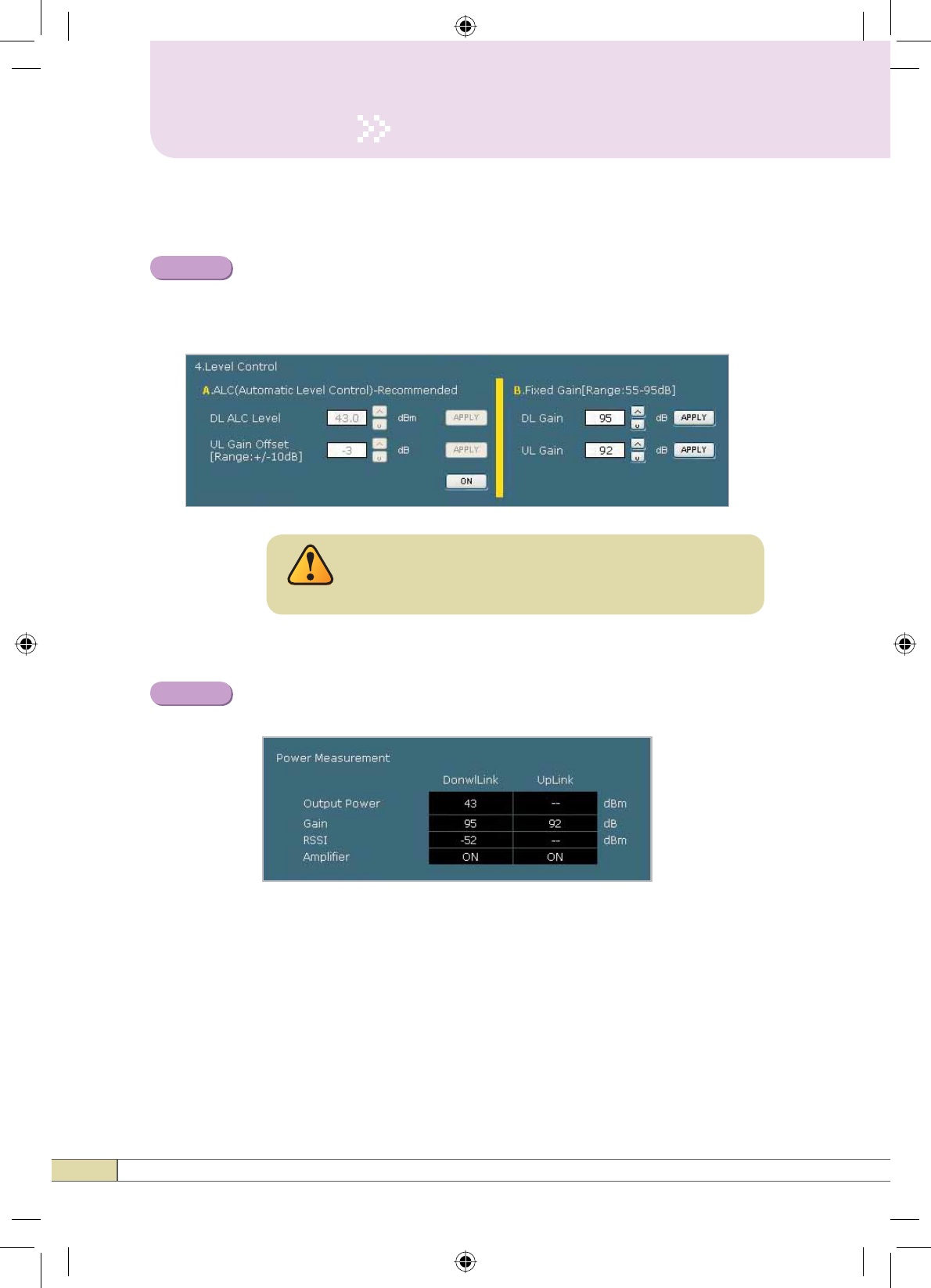
•Automatic Level Control: Type under 43 and then click APPLY and ON.
[Example]
For the repeater with 43dBm maximum output power, 95dB maximum
JDLQG%JDLQFRQWUROUDQJHĺ,ILQSXWVLJQDOG%PDQG$/&LVVHWDV
43dBm, the gain will be 88dB to adjust to the output power.
If input signal is -60dBm, the output power will be 35dBm by the limitation
of the maximum gain even though the ALC is set as 43dBm.
Result 1
Result 2
26
Operation
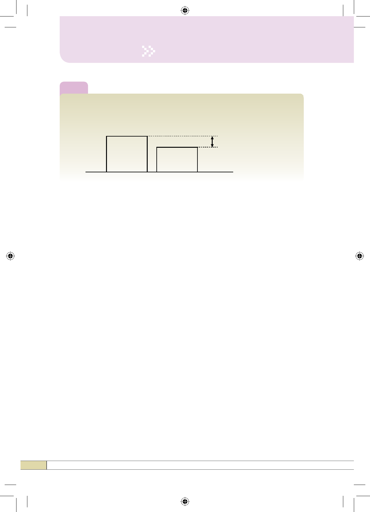
Tip
$SSO\LQJ8SOLQN*DLQ2IIVHW
Perform the following steps to adjust the Uplink Gain by the offset relative to
the Downlink Gain.
Downlink Gain Uplink Gain
Uplink Gain Offset
•Automatic Shutdown: Type the desired values for dBm,seconds, and then
click APPLY. (e.g. 46dBm, 20seconds)
[Example]
For the repeater with 46dBm maximum output power, 95dB maximum gain
/ 40dB gain control range, Assuming ASD Level: 46dBm,ASD Time:
20seconds.
If the output power is 46dBm (ASD LEVEL) and higher, the repeater will
shutdown for 20 seconds (ASD TIME).
Restoration
Restoration recovers the service by turning on the amplifiers of repeater
fundamentally.
After a permanent shutdown, the Restoration turns on the amplifiers of the
repeater at the Restoration Time everyday.
27
Quick Guide
Operation
Solution 2. DL Output Power < Max. 43dBm
Repeat Step 1 through Step 6.
Change the level at Automatic Level Control and click APPLY.
Step 1A
Step 2A
Constant output power set as the ALC level.
Result
28
Operation
Solution 3. Fixed Gain [Not Recommended]
Automatic Easy Setup will calculate the Available Maximum
Gain which defines the maximum gain to be setup.
Repeat Step 1 through Step 6.
Read DL Input Power and the gain controlled by Automatic Easy
Setup.
Step 1B
Step 2B
DO NOT setup the gain higher than the Available
Maximum Gain.
Warning
29
Quick Guide
Operation
Turn off '/$PSOLILHU and 8/$PSOLILHU.
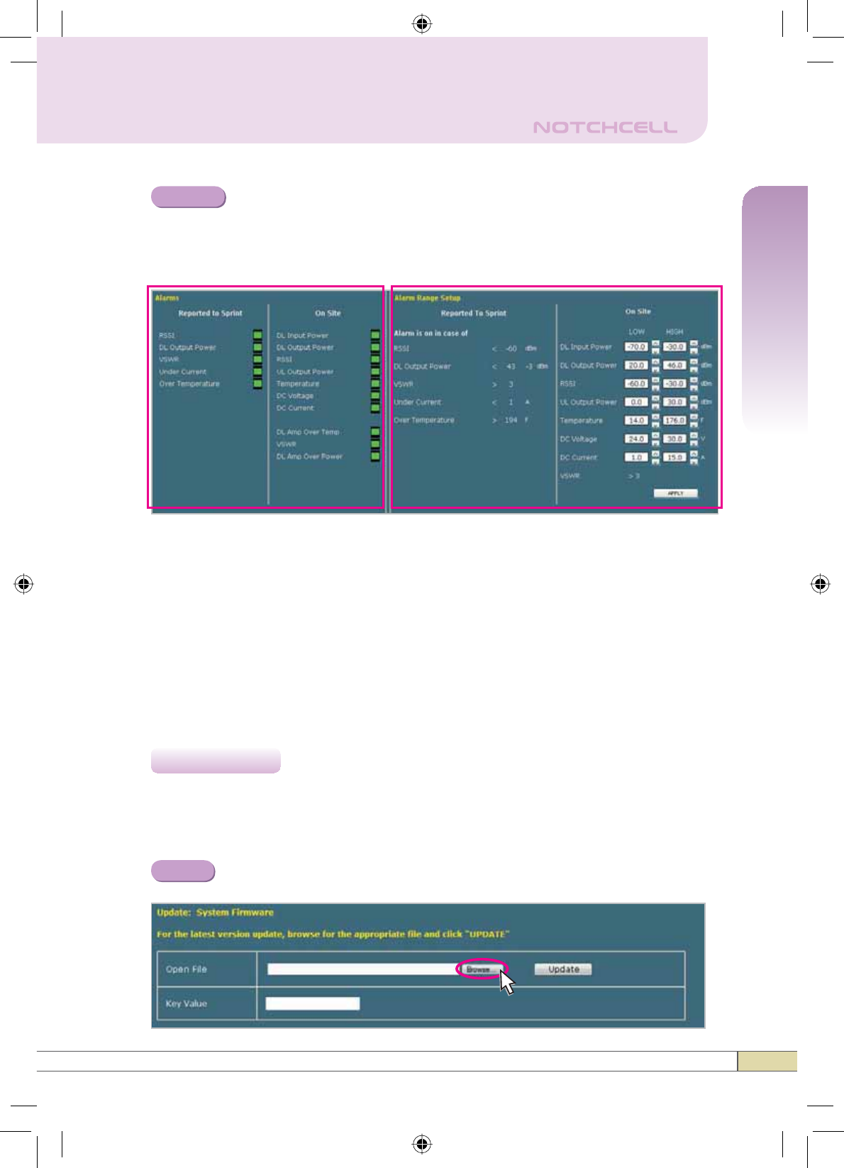
Alarms
< Alarm Status > < Alarm Range >
•Reported to Sprint : If an alarm occurs, the repeater will report directly to
Sprint as a SNMP Trap so the LED of ALARM on the repeater does not blink.
•On Site Alarm : If an alarm occurs, the alarm LED on the repeater will turn
on. Please refer to the troubleshooting section of this manual.
• No change of the values in the alarm range is recommended.
Click Update in the left menu.
5.5.1 Update: System Firmware
Click Browse.
Step 3B
4.5 Update
Step 1
30
Operation
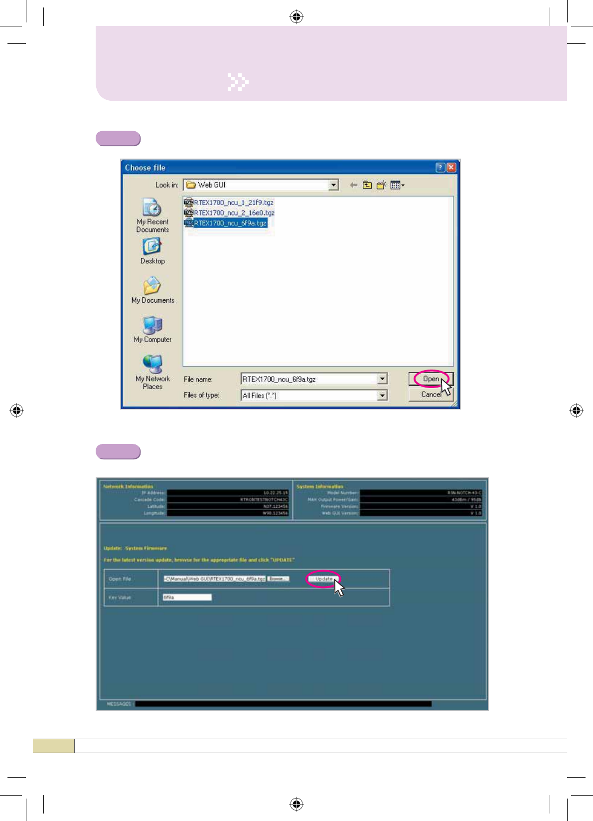
A pop-up window will appear. Select the ILUPZDUHILOH and click Open.
Fill in the Key Value by using the last four characters in the file name and
Click Update.
Step 2
Step 3
31
Quick Guide
Operation
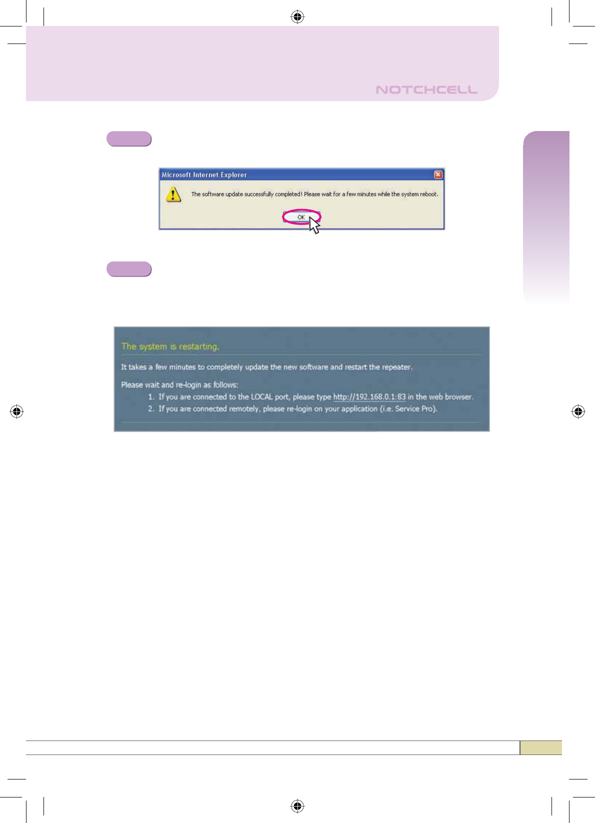
A pop-up window will appear after completing all the update
processes. Click OK to reboot the system.
It will take a few minutes to update the new Web GUI.
If the system reboots, go to the login page and login again.
* Login page: http://192.168.0.1:83 (Local access)
A specified IP address on DHCP(Remote access).
Step 4
Step 5
32
Operation
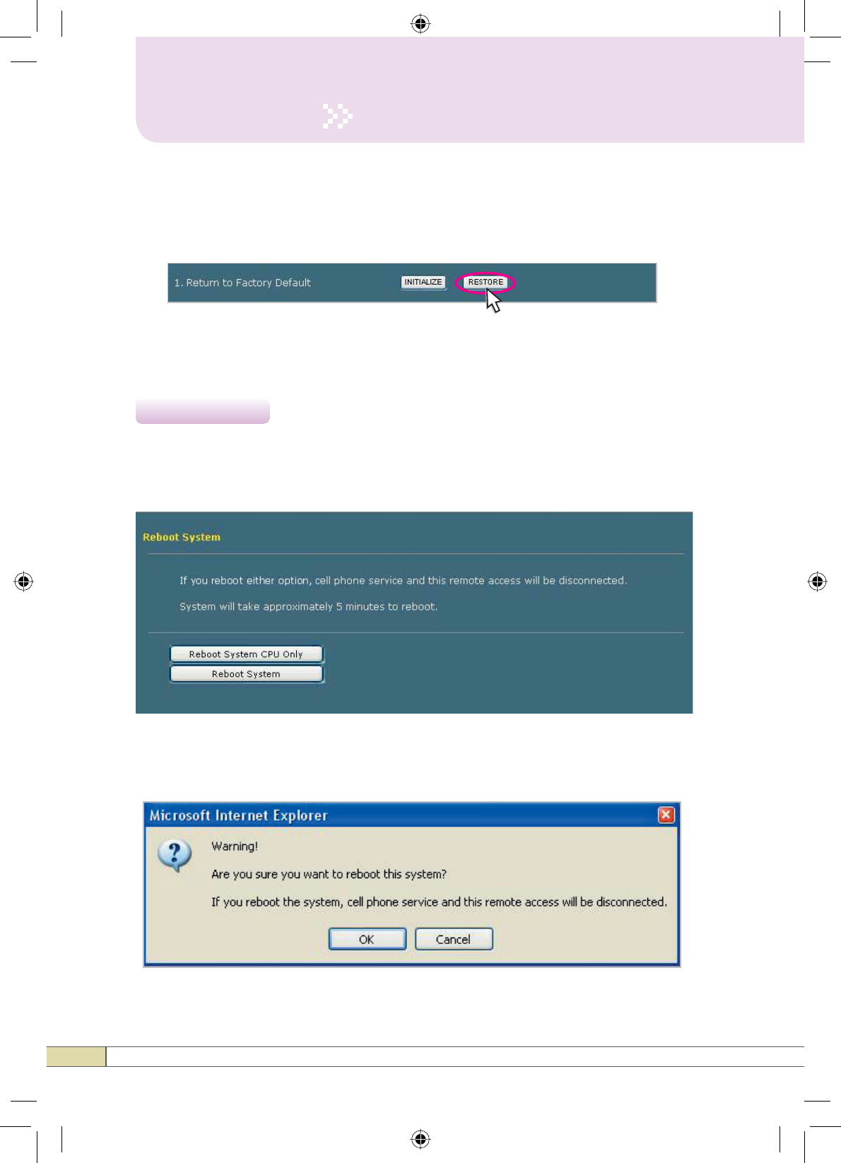
5.5.2 Restore
RESTORE builds up the values of parameters before the initialization.
Click Reboot in the left menu.
In this menu, you can reboot the system.
4.6 Reboot
If you click the button to reboot, the following pop up window appears.
Click OK to reboot the system.
33
Quick Guide
Operation
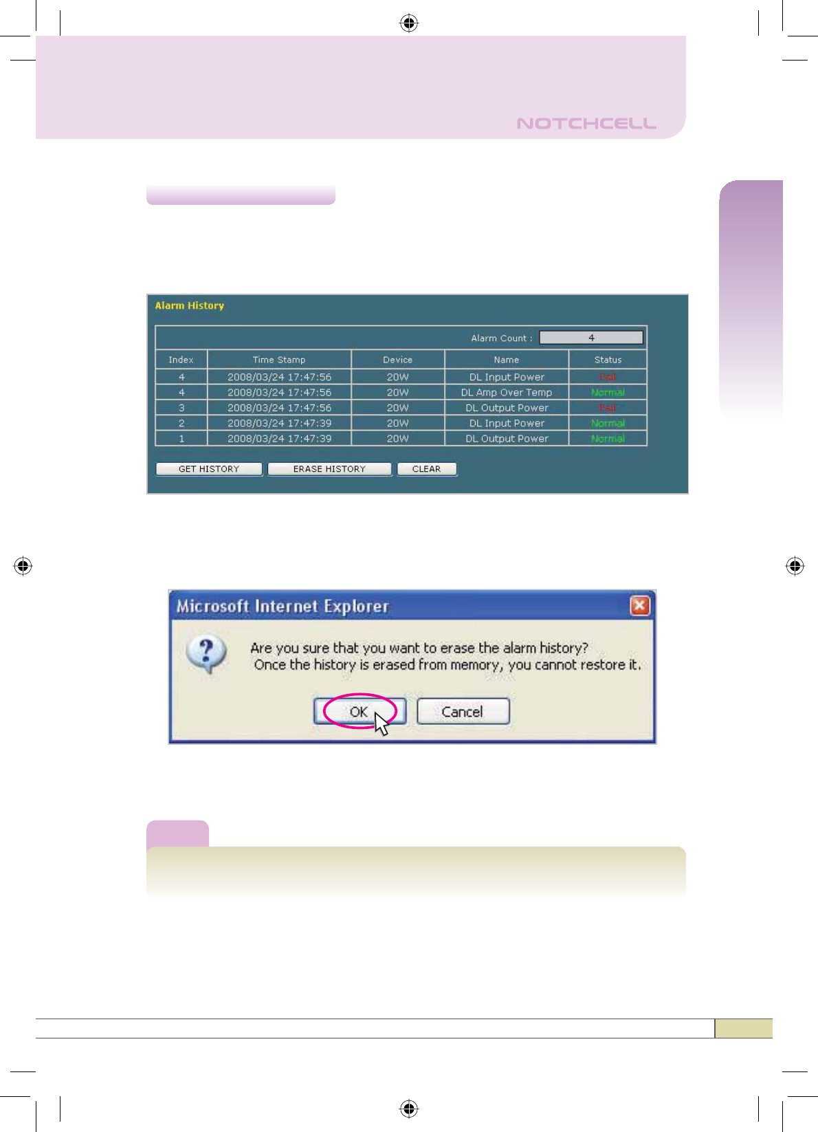
Click Alarm History in the left menu.
Click *(7+,6725<. The history list of alarm issued will be displayed.
4.7 Alarm History
To erase the alarm history on the memory, click (5$6(+,6725<.
A confirmation pop-up window will appear and click OK.
To clear the alarm history on the screen, click CLEAR.
Note
Up to 50 alarm lists can be stored in the memory.
34
Operation
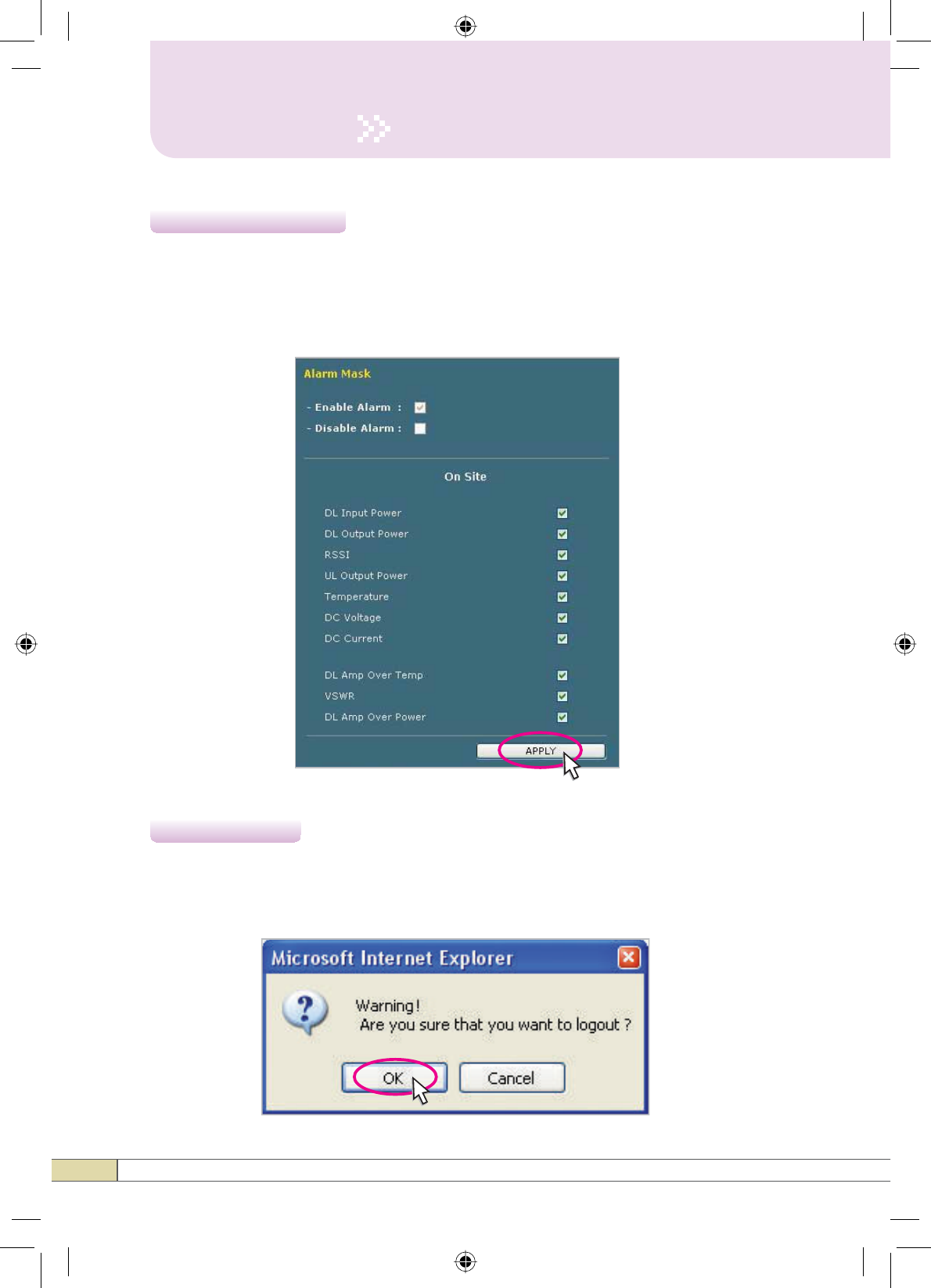
4.8$ODUP0DVN
If you want to logout, click Logout in the left menu.
A warning pop-up window will appear and then click OK to logout.
4.9 Logout
If you enable the alarms by selecting the check boxes, only the checked items
are listed in the alarm history.
To enable the alarm to be saved in the alarm history list, select the check
boxes as shown in the followings:
35
Quick Guide
Appendix
Appendix
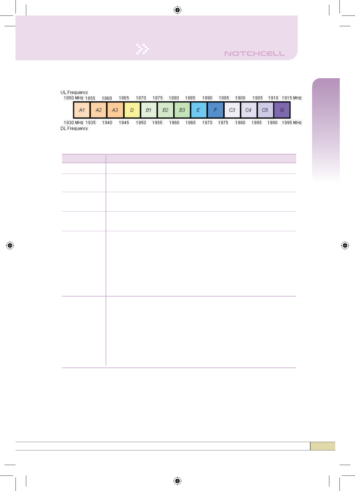
•%DQGZLGWK)UHTXHQF\
7KHYDOXHVRIWKHEDQGZLGWKDQGIUHTXHQF\RI&'0$
10+5 A1A2+D, A1A2+B1, A1A2+B2, A1A2+B3, A1A2+E, A1A2+F,
A1A2+C3, A1A2+C4, A1A2+C5, A1A2+G, A2A3+B1, A2A3+B2,
A2A3+B3, A2A3+E, A2A3+F, A2A3+C3, A2A3+C4, A2A3+C5,
A2A3+G, A3D+B2, A3D+B3, A3D+E, A3D+F, A3D+C3, A3D+C4,
A3D+C5, A3D+G, DB1+B3, DB1+E, DB1+F, DB1+C3, DB1+C4,
DB1+C5, DB1+G, B1B2+E, B1B2+F, B1B2+C3, B1B2+C4,
B1B2+C5, B1B2+G, B2B3+F, B2B3+C3, B2B3+C4, B2B3+C5,
B2B3+G, B3E+C3, B3E+C4, B3E+C5, B3E+G, EF+C4, EF+C5,
EF+G, FC3+C5, FC3+G, C3C4+G
Bandwidth Operating Frequency
5
10
15 A1A2A3, A2A3D, A3DB1, DB1B2, B1B2B3, B2B3E, B3EF, EFC3,
FC3C4, C3C4C5, C4C5G
20 A1A2A3D, A2A3DB1, A3DB1B2, DB1B2B3, B1B2B3E, B2B3EF,
B3EFC3, EFC3C4, FC3C4C5, C3C4C5G
5+5 A1+A3, A1+D, A1+B1, A1+B2, A1+B3, A1+E, A1+F, A1+C3,
A1+C4, A1+C5, A1+G, A2+D, A2+B1, A2+B2, A2+B3, A2+E,
A2+F, A2+C3, A2+C4, A2+C5, A2+G, A3+B1, A3+B2, A3+B3,
A3+E, A3+F, A3+C3, A3+C4, A3+C5, A3+G, D+B2, D+B3, D+E,
D+F, D+C3, D+C4, D+C5, D+G, B1+B3, B1+E, 1+F, B1+C3,
B1+C4, B1+C5, B1+G, B2+E, B2+F, B2+C3, B2+C4, B2+C5,
B2+G, B3+F, B3+C3, B3+C4, B3+C5, B3+G, E+C3, E+C4, E+C5,
E+G, F+C4, F+C5, F+G, C3+C5, C3+G
A1A2, A2A3, A3D, DB1, B1B2, B2B3, B3E, EF, FC3, C3C4,
C4C5, C5G
A1, A2, A3, D, B1, B2, B3, E, F, C3, C4, C5, G
36
Appendix
Bandwidth Operating Frequency
15+5 A1A2A3+B1, A1A2A3+B2, A1A2A3+B3, A1A2A3+E, A1A2A3+F,
A1A2A3+C3, A1A2A3+C4, A1A2A3+C5, A1A2A3+G, A2A3D+B2,
A2A3D+B3, A2A3D+E, A2A3D+F, A2A3D+C3, A2A3D+C4,
A2A3D+C5, A2A3D+G, A3DB1+B3, A3DB1+E, A3DB1+F,
A3DB1+C3, A3DB1+C4, A3DB1+C5, A3DB1+G, DB1B2+E,
DB1B2+F, DB1B2+C3, DB1B2+C4, DB1B2+C5, DB1B2+G,
B1B2B3+F, B1B2B3+C3, B1B2B3+C4, B1B2B3+C5, B1B2B3+G,
B2B3E+C3, B2B3E+C4, B2B3E+C5, B2B3E+G, B3EF+C4,
B3EF+C5, B3EF+G, EFC3+C5, EFC3+G, FC3C4+G
20+5 A1A2A3D+B2, A1A2A3D+B3, A1A2A3D+E, A1A2A3D+F,
A1A2A3D+C3, A1A2A3D+C4, A1A2A3D+C5, A1A2A3D+G,
A2A3DB1+B3, A2A3DB1+E, A2A3DB1+F, A2A3DB1+C3,
A2A3DB1+C4, A2A3DB1+C5, A2A3DB1+G, A3DB1B2+E,
A3DB1B2+F, A3DB1B2+C3, A3DB1B2+C4, A3DB1B2+C5,
A3DB1B2+G, DB1B2B3+F, DB1B2B3+C3, DB1B2B3+C4,
DB1B2B3+C5, DB1B2B3+G, B1B2B3E+C3, B1B2B3E+C4,
B1B2B3E+C5, B1B2B3E+G, B2B3EF+C4, B2B3EF+C5,
B2B3EF+G, B3EFC3+C5, B3EFC3+G, EFC4+G
5+5+5
A1+A3+B1, A1+A3+B2, A1+A3+B3, A1+A3+E, A1+A3+F, A1+A3+C3,
A1+A3+C4, A1+A3+C5, A1+A3+G, A1+D+B2, A1+D+B3, A1+D+E,
A1+D+F, A1+D+C3, A1+D+C4, A1+D+C5, A1+D+G, A1+B1+B3,
A1+B1+E, A1+B1+F, A1+B1+C3, A1+B1+C4, A1+B1+C5, A1+B1+G,
A1+B2+E, A1+B2+F, A1+B2+C3, A1+B2+C4, A1+B2+C5, A1+B2+G,
A1+B3+F, A1+B3+C3, A1+B3+C4, A1+B3+C5, A1+B3+G, A1+E+C3,
A1+E+C4, A1+E+C5, A1+E+G, A1+F+C4, A1+F+C5, A1+F+G,
A1+C3+C5, A1+C3+G, A1+C4+G, A2+D+B2, A2+D+B3, A2+D+E,
A2+D+F, A2+D+C3, A2+D+C4, A2+D+C5, A2+D+G, A2+B1+B3,
A2+B1+E, A2+B1+F, A2+B1+C3, A2+B1+C4, A2+B1+C5, A2+B1+G,
A2+B2+E, A2+B2+F, A2+B2+C3, A2+B2+C4, A2+B2+C5, A2+B2+G,
A2+B3+F, A2+B3+C3, A2+B3+C4, A2+B3+C5, A2+B3+G, A2+E+C3,
A2+E+C4, A2+E+C5, A2+E+G, A2+F+C4, A2+F+C5, A2+F+G,
A2+C3+C5, A2+C3+G, A2+C4+G, A3+B1+B3, A3+B1+E, A3+B1+F,
A3+B1+C3, A3+B1+C4, A3+B1+C5, A3+B1+G, A3+B2+E, A3+B2+F,
A3+B2+C3, A3+B2+C4, A3+B2+C5, A3+B2+G, A3+B3+F, A3+B3+C3,
A3+B3+C4, A3+B3+C5, A3+B3+G, A3+E+C3, A3+E+C4, A3+E+C5,
A3+E+G, A3+F+C4, A3+F+C5, A3+F+G, A3+C3+C5, A3+C3+G,
A3+C4+G, D+B2+E, D+B2+F, D+B2+C3, D+B2+C4, D+B2+C5, D+B2+G,
D+B3+F, D+B3+C3, D+B3+C4, D+B3+C5, D+B3+G, D+E+C3, D+E+C4,
D+E+C5, D+E+G, D+F+C4, D+F+C5, D+F+G, D+C3+C5, D+C3+G,
D+C4+G, B1+B3+F, B1+B3+C3, B1+B3+C4, B1+B3+C5, B1+B3+G,
B1+E+C3, B1+E+C4, B1+E+C5, B1+E+G, B1+F+C4, B1+F+C5, B1+F+G,
B1+C3+C5, B1+C3+G, B1+C4+G, B2+E+C3, B2+E+C4, B2+E+C5,
B2+E+G, B2+F+C4, B2+F+C5, B2+F+G, B2+C3+C5, B2+C3+G,
B2+C4+G, B3+F+C4, B3+F+C5, B3+F+G, B3+C3+C5, B3+C3+G,
B3+C4+G, E+C3+C5, E+C3+G, E+C4+G, F+C4+G