R tron SP-APA-002 PCS Band CDMA Repeater User Manual
R-tron Inc. PCS Band CDMA Repeater
UserManual.wiki
>
R tron
>
SP APA 002 User Manual
Manual
Navigation menu
Upload a User Manual
Namespaces
Wiki Guide
HTML
PDF
Info
Views
User Manual
Discussion / Help
Navigation


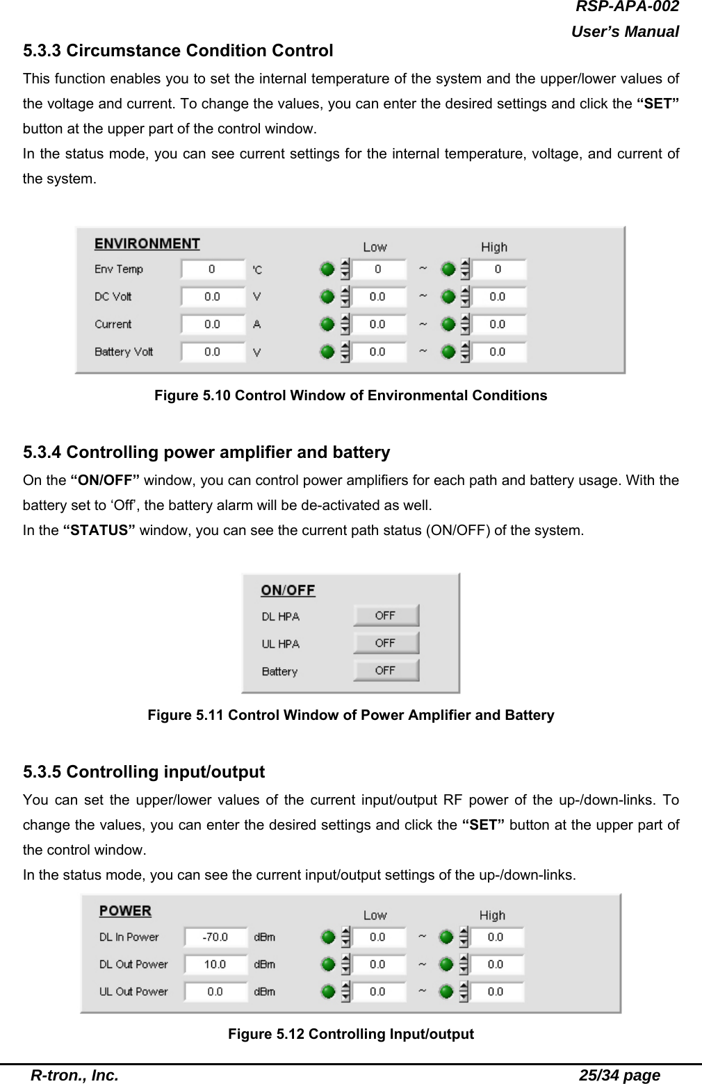
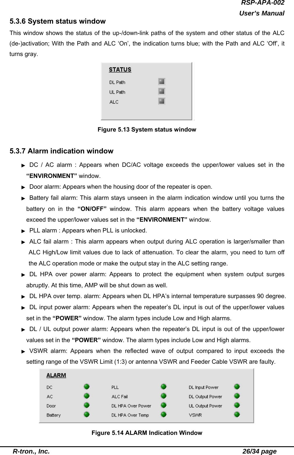

![RSP-APA-002 User’s Manual R-tron., Inc. 29/34 page goes back to the active status after the ‘Shutdown-on’ time. If the output of the repeater is higher than the set target value, the repeater will be de-activated again after the set ‘Shutdown-off’ time. The repeater repeats the process by the Shutdown count. If the output of the repeater still exceeds the target value after the repetitive work, the repeater will turn completely off. Figure 5.18 ALC Setting window 5.3.8.4 Time set When you press the Time set button at the menu window, the window seen in Figure 5.19 appears. When you click the Set button in the window, MCU automatically reads the time of the PC for time setting. The set time appears on the RTC Time on the SYSTEM window [See the Figure 5.8]. Figure 5.19 Time set window 5.3.8.5 Reset This function clears communication status, rebooting the MCU. When you press the Reset button, current communication status is reset. It leads to MCU rebooting and then resets the communication status. Then, the information on the current system is displayed on the screen.](https://usermanual.wiki/R-tron/SP-APA-002/User-Guide-649521-Page-29.png)
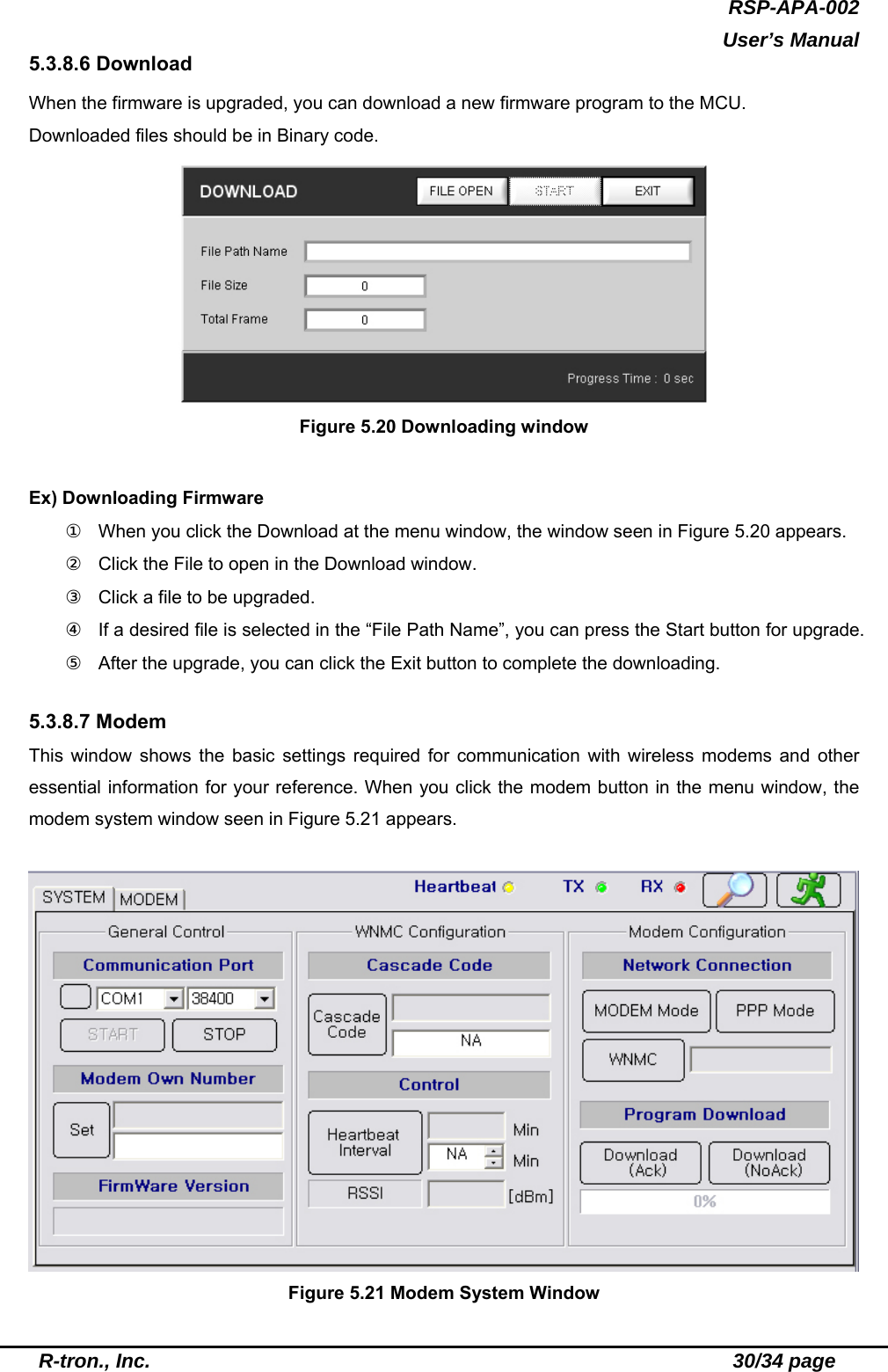
![RSP-APA-002 User’s Manual R-tron., Inc. 31/34 page 1. Modem system window ▶ General control - Communication Port : Connects MCU to the modem port. You can refer to the same settings as those in the main GUI. - Modem own number : Refers to the modem number, with which you can call using a modem. - Firmware version : Refers to the version of currently used software. ▶ WNMC configuration - Cascade code : Refers to the ID designated by operator where the repeater is installed. The ID is composed of ten-digit characters and figures. It may appear in the following form: XX##YY$$$$ ① XX : First two-digit characters showing the installation site of the repeater. If the repeater is installed in Boston, XX is seen as ‘BS’. ② ## : Shows whether the repeater is installed inside/outside of a building: In Building System (Indoor type)/Macro System (Outdoor type). ③ YY : Shows device types (Repeater/cell site). If the system is found as repeater, YY is ‘XR’; if it is a cell site, YY is ‘XC’. ④ $$$$ : Refers to integers (1 ~ 9,999) indicating the number of repeaters installed in XX. If 24 repeaters are installed in Boston (BS), $$$$ is ‘24’. ▶ Control The Control window is to set the periodic interval of the Heartbeat. This function lets you set the time interval of the Heartbeat to 3 ~ 59 minutes. ▶ Modem Configuration - Network Connection : ① Modem mode : This button lets you see the modem status. When you press the button, the Modem Status window, the Modem Configuration window, the Modem Statistics window, and the Modem Status window are activated. With the [NMST] button in the Modem Status window, you can see modem status. ② PPP mode : Stands for Point to Point Protocol, which helps set connection between the MCU and WNMC. PPP connection is automatically set. Facing connection failure, MCU retries until the connection is successful. When PPP is fully set, the Modem Status window, the Modem Configuration window, and the AT Command window are automatically de-activated. ③ WNMC : This button lets you clear PPP connection. You can see whether PPP is connected/disconnected depending on the icon color of the WNMC button. You can see the connection status in the window next to the WNMC button. You can have access to the PPP](https://usermanual.wiki/R-tron/SP-APA-002/User-Guide-649521-Page-31.png)