Manual

RSP-APA-002 (A-Band)
User’s Manual

RSP-APA-002
User’s Manual
R-tron., Inc. 2/34 page
Contents
1. Overview ------------------------------------------------------------------------ 5
2. Specifications ---------------------------------------------------------------- 6
2.1 System specifications ------------------------------------------------------- 6
2.2 Antenna specifications ------------------------------------------------------ 8
2.3 Donor Antenna Diagrams -------------------------------------------------- 9
2.4 Distributor Antenna Diagrams ------------------------------------------- 10
3. System Configuration -------------------------------------------------- 11
3.1 Block Diagram --------------------------------------------------------------11
4. Installation ---------------------------------------------------------------------12
4.1 Installation Overview -------------------------------------------------------12
4.2 Safety -----------------------------------------------------------------------12
4.3 Installation information -----------------------------------------------------12
4.4 Installing the repeater & Antenna ---------------------------------------13
5. Graphic User Interface (for maintenance) ------------------- 22
5.1 GUI Overview --------------------------------------------------------------- 22
5.2 Preliminary steps for GUI Execution & Maintenance ------------- 23
5.3 How to operate GUI & Functions -------------------------------------- 25

RSP-APA-002
User’s Manual
R-tron., Inc. 3/34 page
1. Overview
Figure 1.1 RSP-APA-002 Repeater
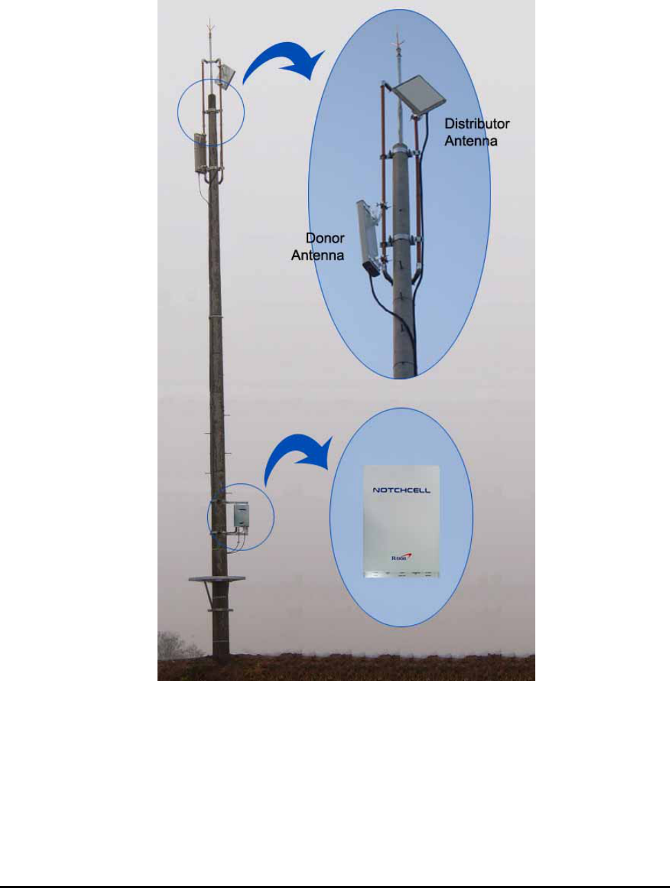
R-tron RSP-APA-002 Repeater can be used in CDMA service hole spots like in-buildings,
underground and tunnels to cover its service area. This repeater system designed for dual and
simultaneous service, namely, it receives signals from the base station through donor antenna,
amplifies the signals and re-transmits it to one or other mobile terminals. Also, it amplifies the signals
which comes from mobile terminals through distributor antenna and re-amplifies it to base station.
Using local OMT(Operation and Maintenance Terminal) which is connected between repeater
control board and personal or laptop computer, it is possible to check or to control repeater status.
With wireless modem which is in the repeater, it also enables to monitor Sprint WNMC(Wireless
Network Management Center) in a remote place.

RSP-APA-002
User’s Manual
R-tron., Inc. 4/34 page
2. Specifications
2.1 Repeater specifications
SPECIFICATION
ITEM
DOWN-LINK UP-LINK
Repeater Type Band Specific
Frequency Band A-Band
Frequency Bandwidth 15MHz
Frequency Range 1930 ~ 1945MHz 1850 ~ 1865MHz
CDMA Frequency Error < ± 0.05ppm
Rho (Pilot Only) > 0.912
RF Output Power 34dBm / Total 23dBm / Total
Operating ~ -35dBm ~ -35dBm
RF Input Level Maximum -10dBm
System Gain 65~95dB
Gain Control 0 ~ 30dB/1dB step
ALC(Automatic Level Control) 10~34dBm -
ASD(Automatic Shut Down) 10~37dBm -
Fc ± 885kHz Min. 45dBc Min. 45dBc
Fc ± 1.98MHz Min. 55dBc Min. 50dBc
Spurious
Emission Fc ± 2.25MHz Max. -13dBm Max. -13dBm
Noise Power In-band Max. -13dBm / RBW, 1.23MHz
Noise Figure Max. 5dB
Ripple In Band Max. 2dB
Characteristic Gain In Band ± 2dB
3dB Min. 14MHz
Selectivity 40dB Max. 16MHz
System Group Delay Max. 5 microseconds
V.S.W.R Max. 1.5 : 1
RF Measurement Port 30dB ± 1dB
Impedance 50Ω
Operating Temperature / Humidity -30 ~ 50 / Max.℃ 95%
Cooling Air Convection / Heat sink
Antenna Port Type-N female
RF Connector Coupling Port Type-SMA female
Local OMT RS-232C
Wireless Modem 1X modem, SNMP

RSP-APA-002
User’s Manual
R-tron., Inc. 5/34 page
Input voltage 110Vac +30%/-20%
Size (W x H x D) 600 X 400 X 262 mm / 23.62 x 15.75 x 10.31 in
Weight Less than 36.5Kg / Less than 80.47 lbs
Table 2.1 Repeater Specification
Figure 2.1 A body of the RSP-APA-002
RSP-APA-002
User’s Manual
R-tron., Inc. 6/34 page
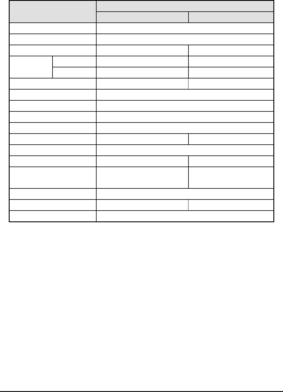
2.2 Antenna Specifications
Specification
Parameter
Donor Distribution
Frequency range 1850 ~ 1990MHz
Frequency bandwidth 140MHz
Antenna gain 16dBd ±1dB 12dBd ±1dB
Horizontal 20°±3° 48°±5°
Beam width
Vertical 20°±3° 25°±3°
Polarization Horizontal/Vertical Vertical
VSWR < 1.5
First Sidelobe Suppression > 13dB
Impedance 50 Ω
Power Capability 200 Watts
Front to back ratio > 40dB > 40dB
Antenna Connector Port Type 1x7/16-Female
Weight 9kg / 19.8lbs 5.5kg / 12.1lbs
Dimension (W x H x D) 530 x 530 x 70 mm
(21.2 x 21.2 x 2.8 inch)
500 x 300 x 110 mm
(20.0 x 12.0 x 4.4 inch)
Mounting Pole or Wall
Radome(color) ASA FRP (Grey)
Wind load (at 150 km/h) Front : 534 N Side : 107 N Rear : 534 N
Table 2.2 Antenna Features
RSP-APA-002
User’s Manual
R-tron., Inc. 7/34 page
2.3 Donor Antenna Diagrams
Figure 2.2 Donor Antenna
RSP-APA-002
User’s Manual
R-tron., Inc. 8/34 page
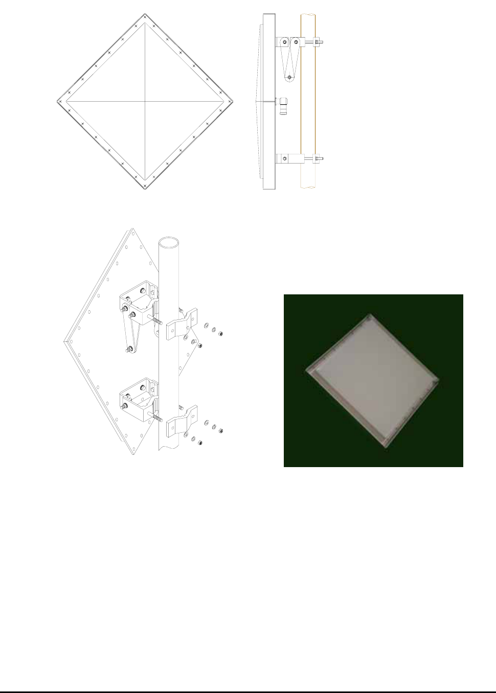
2.4 Distributor Antenna Diagrams
Figure 2.3 Distributor Antenna
RF EXPOSURE INFORMATION
The antenna used for this transmitter must not exceed 20dBi and must be installed to
provide a minimum separation distance of 1.5m from all persons.
RSP-APA-002
User’s Manual
R-tron., Inc. 9/34 page
3. System Configuration
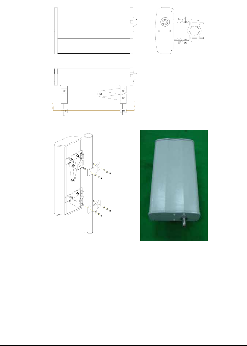
3.1 Block Diagram
Figure 3.1 shows the block diagram of a band specific repeater.
This diagram is applicable to repeaters for CDMA systems.
3.1.1 Downlink signal path
DL signal path gives a wireless mobile terminal path after receiving signal from base station,
amplifying and noise filtering. Please refer to the following picture 3.1, RSP-APA-002 repeater block
diagram.
3.1.2 Uplink signal path
UL signal path gives a path after receiving signal from mobile terminal, amplifying and noise filtering.
Please refer to the following picture 3.1, RSP-APA-002 repeater block diagram.
PLL:Variable
Donor Ant.
G : 16dBd
RF Input range
-61 ~ -31 dBm
HPA
PLL:Variable
System Gain : 95 dB
System Gain : 95 dB
RF
SA
W
Att.(1)
Att.(3)
Att.(2)
15MHz (or 5MHz)
SAW Filter
RF
SA
W
Att.(1)
Att.(3)
Att.(2)
Distributor Ant.
G : 12dBd
RF Output (UL)
23dBm/Total
RF Input range
-72 ~ -42 dB
m
+45 dB
45dB
-2 dB
-2 dB +54 dB
HPA
45dB
-63 ~ -33 dBm
15MHz (or 5MHz)
SAW Filter
36 dBm-9 dBm
+45 dB -2 dB
-2 dB +54 dB
-74 ~ -44 dBm25 dBm -20 dBm
Duplexer
RF Output (DL)
34dBm/Total
Duplexer

RSP-APA-002
User’s Manual
R-tron., Inc. 10/34 page
4. Installation
4.1 Installation Overview
The following gives you guide how you can install R-tron repeater properly, considering field
situation and installation specific conditions.
4.2 Safety
4.2.1 Purpose
The following information gives you how you can proceed your job correctly and eliminate
dangerous condition.
4.2.2 Application Range
Installation supervisor should check and do the proper thing to check preliminary dangerous
condition.
4.3 Installing information
4.3.1 Right-of-way
- The repeater shall be installed in the location owned or leased by the carrier.
- If the repeater is installed on the roof, an appropriate space for the installation must be
considered.
4.3.2 Conditions for the Installation space
Repeater should be installed as followings :
Roof
- Avoid certain part which is located something heavy or water tank on the roof, considering
weight balance.
- Select certain place which is good for air ventilation.
- There will be enough space to check the repeater.
RSP-APA-002
User’s Manual
R-tron., Inc. 11/34 page
4.4 Installing the repeater & Antenna
The installation of the repeater depends on the types of support, location, and the demand of
the carrier.
Figure 4.1 Repeater Installation (electric pole type)

RSP-APA-002
User’s Manual
R-tron., Inc. 12/34 page
4.4.1 General Condition
- Check whether the repeater status is correctly horizontal angle.
- Check whether there is enough space for maintenance and repair.
- About roof-top steel pole, its feeder line should be installed 3 points at least or more.
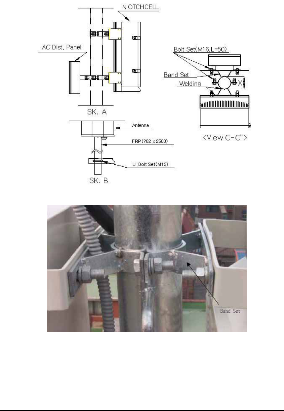
4.4.2 Installing Band set
- Repeater main box should be installed 8.2 inches at least, above from the ground.
- When you install the repeater main box, do not impact on its installation to other repeaters
maintenance.
- Safety plate should be installed 8.2 inches at least, above from the ground.
RSP-APA-002
User’s Manual
R-tron., Inc. 13/34 page
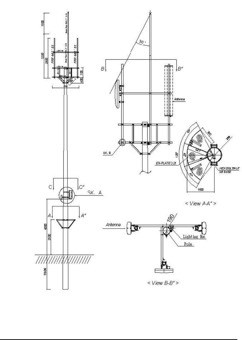
Figure 4.2 Band installation diagram (electric pole type)
RSP-APA-002
User’s Manual
R-tron., Inc. 14/34 page
Figure 4.3 Band installation diagram 2 (location of repeater)
Figure 4.4 Band set

RSP-APA-002
User’s Manual
R-tron., Inc. 15/34 page
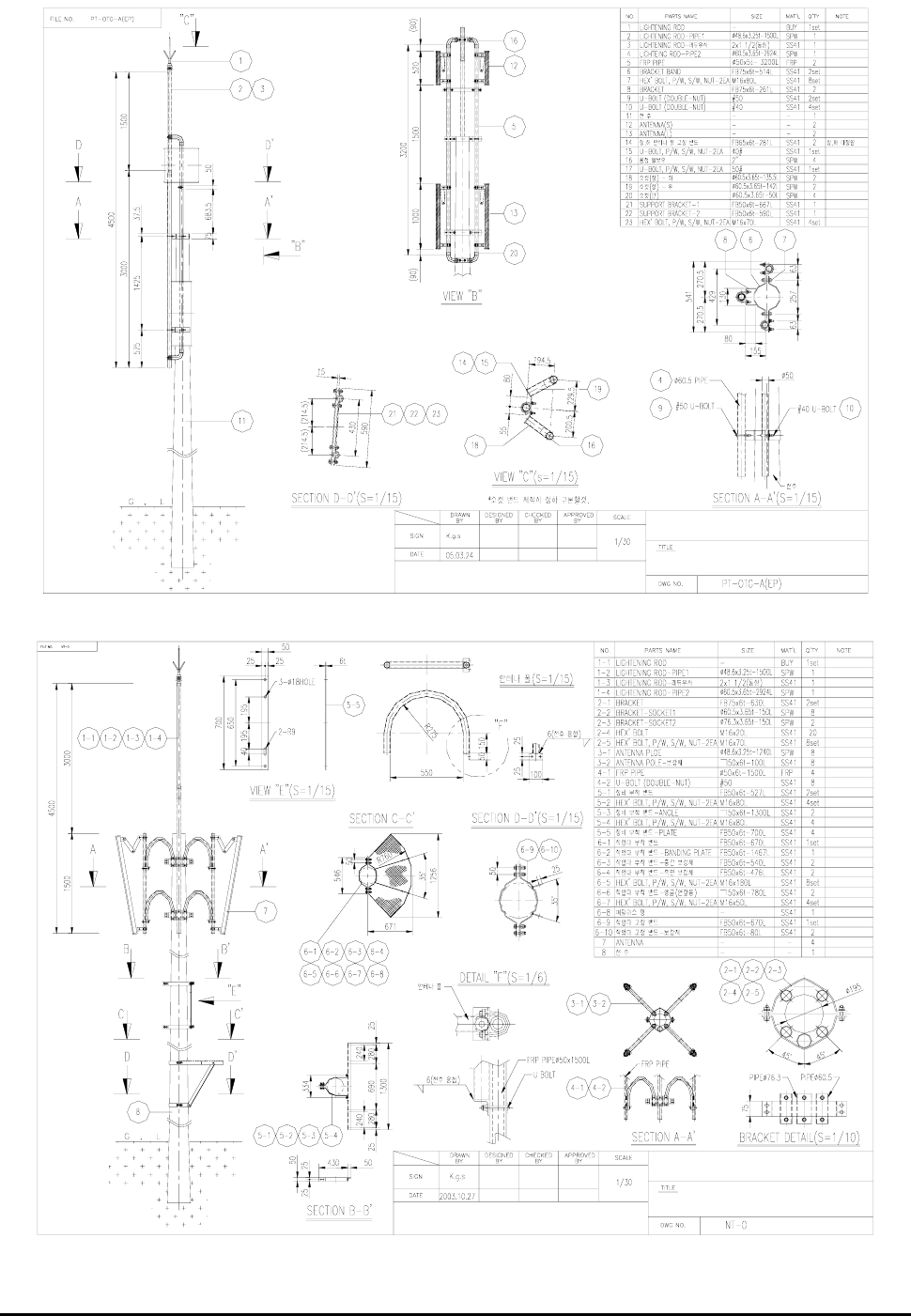
4.4.3 Installing Antenna
4.4.3.1 Precautions
- Antenna is an elaborated device. Therefore, be careful, not damaged and not transform.
- When you install the antenna, do not hurry and do not overpower.
- Antenna sustain plate should be zinc.
- Select proper antenna installation candidate place which keeps away from topological
obstacles or higher buildings for good frequency receipt and transmittance.
- Install antenna in a place which is not blocked or sufficiently isolated from the high-
voltage cable to avoid spurious signal.
- An angle between each antenna and sustain plate should be under 60 degrees.
4.4.3.2 Installing Antenna
- Antenna should be fixed firmly and do not shake by external impact or wind.
- Using FRP(Φ48.6x2500), antenna fix pipe can be fastened.
- Between donor and distributor antenna should be isolated 59 inches at least.
- To avoid antenna shivering, donor and distributor pipes should be fixed by an angle.
RSP-APA-002
User’s Manual
R-tron., Inc. 16/34 page
Electric Pole (2)
Electric Pole (1)
Figure 4.5 Antenna Installation

RSP-APA-002
User’s Manual
R-tron., Inc. 17/34 page
4.4.4 Installing the feeder cable
4.4.4.1 General Condition
- Coaxial main power line should be handled carefully when you move it to another place
or keep it in the warehouse. Especially be careful for humidity and rainwater inflow.
- Cable should be installed as short as possible, be straight, not be curved, with tagged.
- Cables should be installed not twisted, not crossed and maintaining allowed
line of curvature.
4.4.4.2 Coaxial Main Power Line Installation
- About coaxial main power installation in the pole, 1/2”shield coaxial main power cable
can be used. As for big steel pole, you can use 7/8” .
- 1/2” shield coaxial main power line should be in flexible cable tube.
About 7/8” shield coaxial main power line can be installed without flexible cable tube.
- Shield outlet should be water-proof for connector connection.
- Flexible cable tube outlet should be directly connected with repeater main box and
antenna for rainwater inflow.
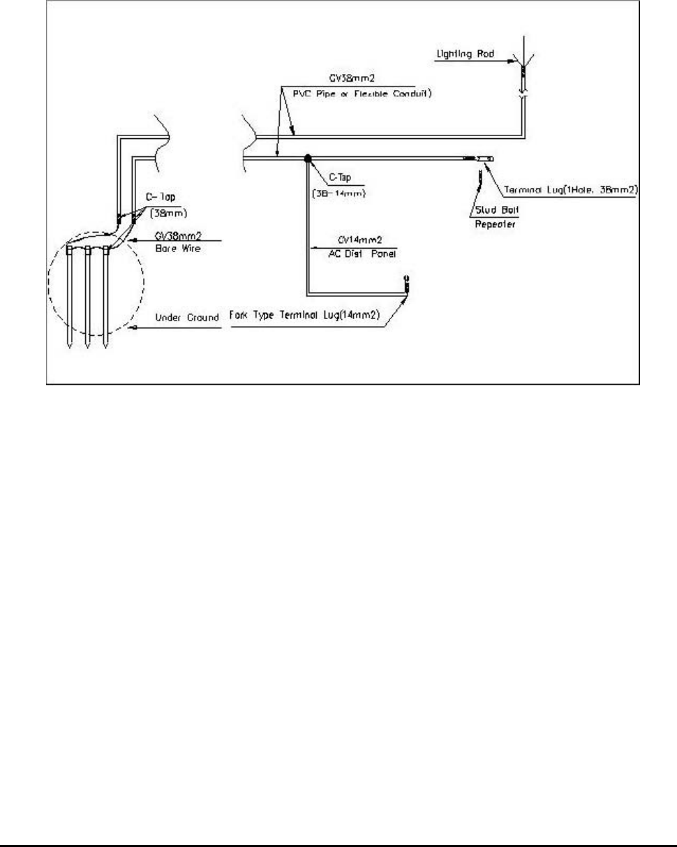
4.4.5 Grounding
-Three types of grounding are applied – system, arrester and steel tower grounding.
-The arrester and the fixing studs are installed on the bottom of the repeater.
-The steel tower grounding and arrester grounding should conform to the steel tower
manufacturer’s standards.
4.4.5.1 General Condition
- GV cable can be used ground line.
- Using C-Tap, distribution part should be closed and do not get into rainwater
to the distribution part.
- About cable installation, you can use cable rack. As for the wall, you can firmly fixed
the cable with saddle instead of cable rack, when there isn’t cable rack.
- Ground cable should be covered by PVC flexible pipe or flexible cable tube for protection.
4.4.5.2 System grounding
RSP-APA-002
User’s Manual
R-tron., Inc. 18/34 page
- Installation should be done within max. ground 3pcs or ground resistance 20 ohm.
- Dig 27.55 inches from the ground and isolate over 118 inches at least and then
drive in ground pole.
- Drive thunder arrest outlet in the ground, using GV 38mm² x 1C
- To preserve ground line, put ground line into zinc cable(length 141.73 inches).
Figure 4.6 Ground Cable Diagram
4.4.5.3 AC distribution panel grounding
To protect the AC distribution panel from surges, connect the GV 14㎟ cable to the repeater
cabinet grounding cable (GV 38㎟), branching it off with C-Tap (38-14mm).
RSP-APA-002
User’s Manual
R-tron., Inc. 19/34 page
4.4.6 Installing AC power cable
4.4.6.1 General Condition
- Using compressed outlet, power cable outlet should be installed. Avoid voltage down as
the result of connection resistance between repeater outlet and main power.
4.4.6.2 Installing AC power cable
- Main cable is composed of a rectifier, AC & DC power.
Repeater input power is AC and output power is DC.
- After putting AC power cable(CV 5.5mm² x 2C) into flexible Conduit(22mm) and then
installed it.
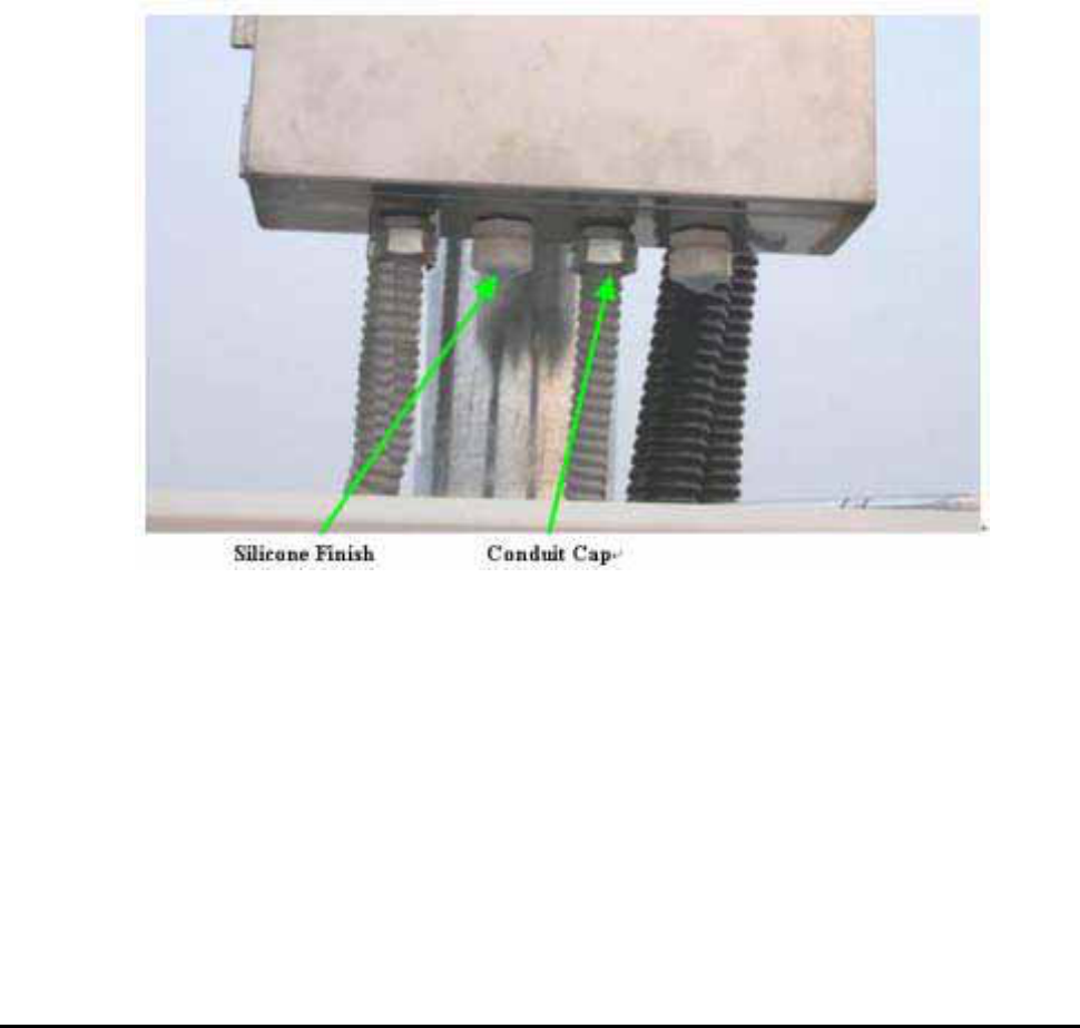
Figure 4.7 Flexible Conduit End Fitting
4.4.6.3 AC Power Box Installation
- AC power box input and output main power should be connected with terminal outlet
which is inside AC power box.
- AC Power Box should be installed firmly upper side in the repeater, isolating
11.81 inches
RSP-APA-002
User’s Manual
R-tron., Inc. 20/34 page
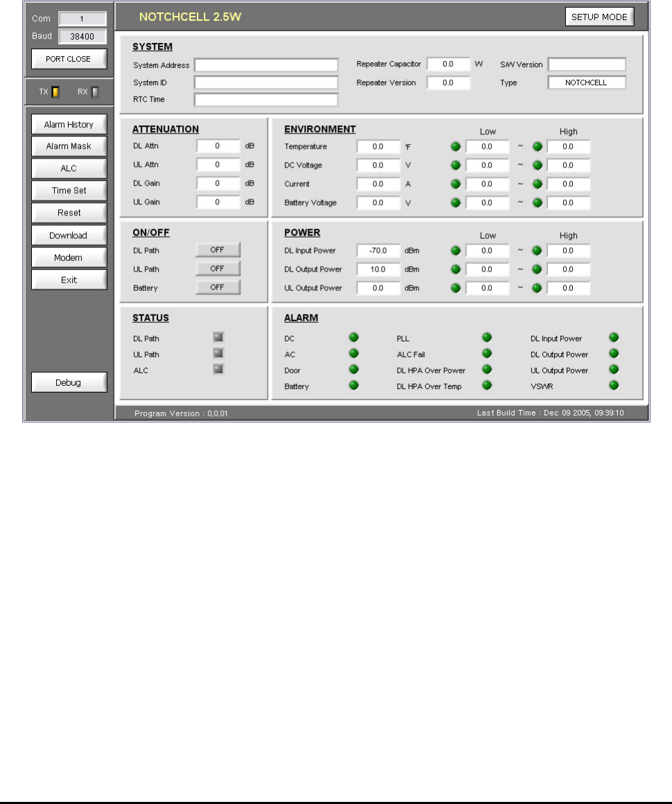
5. Graphic User Interface (for maintenance)
5.1. Overview
The following picture is RSP-APA-002 GUI Configuration.
Figure 5.1 Main window
When you first execute main window, you can see the above picture and it show you repeater status.
RSP-APA-002
User’s Manual
R-tron., Inc. 21/34 page
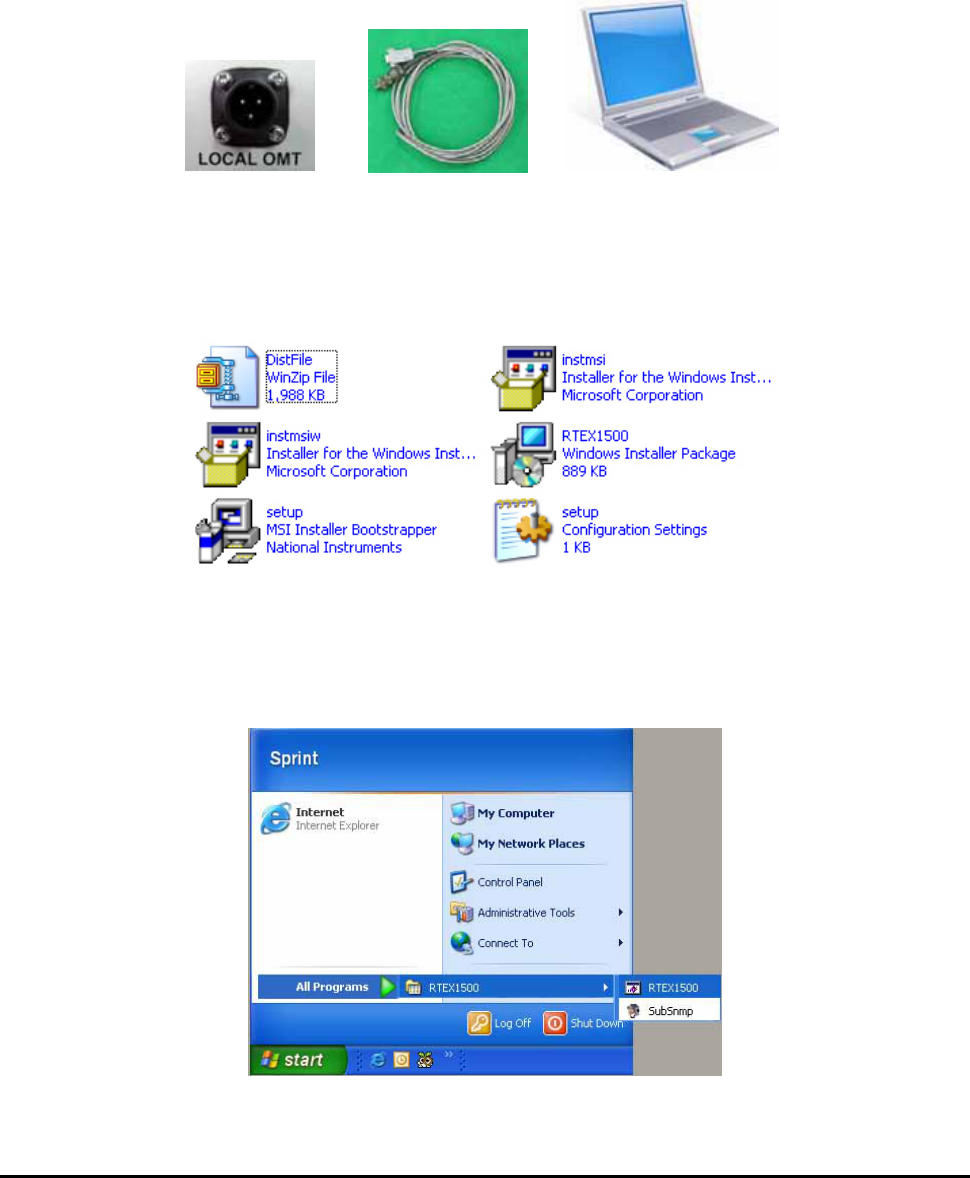
5.2 Preliminary Steps for GUI Execution & Maintenance
5.2.1 Preliminary Steps before using GUI
a. Check all connection status during the installation.
b. Set the baud rate which you are going to use.
c. Connect the repeater main power cable.
d. Connect RSP-APA-002 “LOCAL OMT” with PC, using RS232 cable.
Figure 5.2 Connection RSP-APA-002 with PC
5.2.2 Executing GUI program
a. Click “setup.exe” which is in GUI folder and then install GUI program.
Figure 5.3 GUI Folder
b. When you finish the file installation, execute GUI program “RTEX 1500”.
(Start -> All Programs -> TREX1500 -> RTEX1500)
Figure 5.4 GUI Program Execution
RSP-APA-002
User’s Manual
R-tron., Inc. 22/34 page
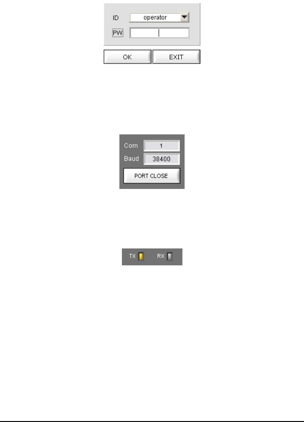
c. When you execute the GUI program, you can see the login pop-up window.
(ID : operator / Password : spcs)
Figure 5.5 login pop-up window
d. When you execute the GUI program, the main window is opened. And then set the communication
speed button witch is in the up-left side, communication can be started.
(Communication Speed : 38,400 bit per a second)
Figure 5.5 Personal Computer Port Connection
5.2.3 GUI Communication
When the communication between Personal Computer and Repeater MCU board is OK, Tx/Rx yellow
LED which is up-left corner in the GUI screen will be flashed.
Figure 5.6 Communication Verification LED
RSP-APA-002
User’s Manual
R-tron., Inc. 23/34 page
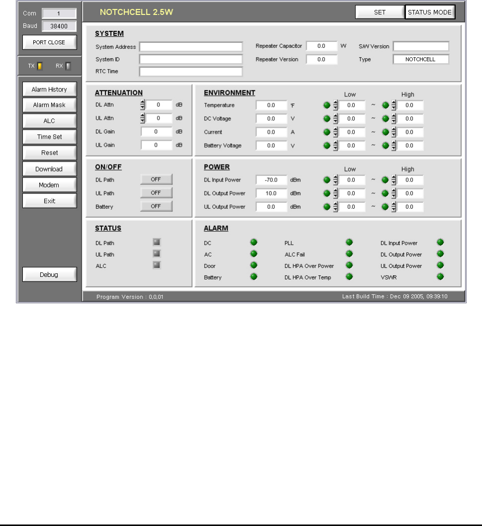
5.3 How to operate GUI and Functions
Repeater can be controlled in Set-up mode. In Set-up pop-up window, you can input the value and
control DL/UL Path, ALC, Shut down and attenuation. When you are going to change the setting value,
you should click “Set” button which is in up-right side in the GUI screen.
When you are going to check repeater status, click “Status mode” button which is in the up-right side
in the screen. And then check the value which is displayed in “Status mode” and you can change
output value, using attenuation value. After setting output value, you can set ALC/ASD level value,
using ALC button.
Figure 5.7 Setup mode
RSP-APA-002
User’s Manual
R-tron., Inc. 24/34 page
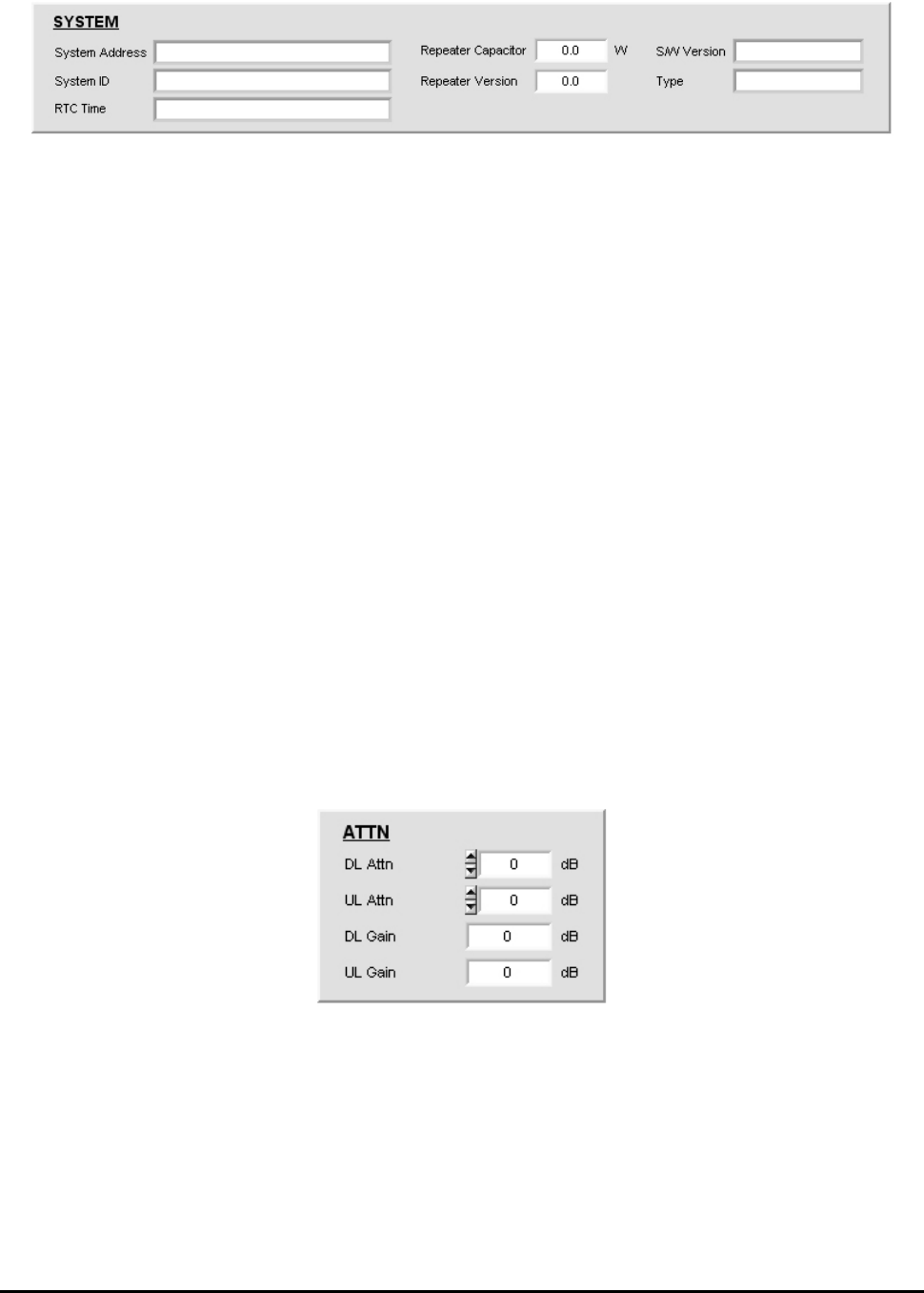
5.3.1 Pop-up window for repeater information indication
Figure 5.8 Pop-up window for repeater information indication
▶ System Address : Indicates where the repeater is installed.
▶ System ID : Allocated number from base station. (from 0 to 16383)
For example, when PCS & A band system ID is 0, Service will be indicated as
“PCS B 0”.
▶ RTC Time: Display current time which currently set in MCU.
When repeater time is incorrect, you can change it correctly, using Time Set in the
menu bar.
▶ Repeater Capacitor : Repeater output
▶ Repeater Version : H/W version
▶ S/W Version : Repeater program version
▶ Type : Repeater type
5.3.2 How to set repeater gain
System gain value can be changed using Down/Up link attenuation value control which is in “ATTN”
pop-up window. Available set attenuation value is from 0 to 30 dB, Down/Up Link both.
You can check current system gain in status mode.
Figure 5.9 Gain Setting
RSP-APA-002
User’s Manual
R-tron., Inc. 25/34 page
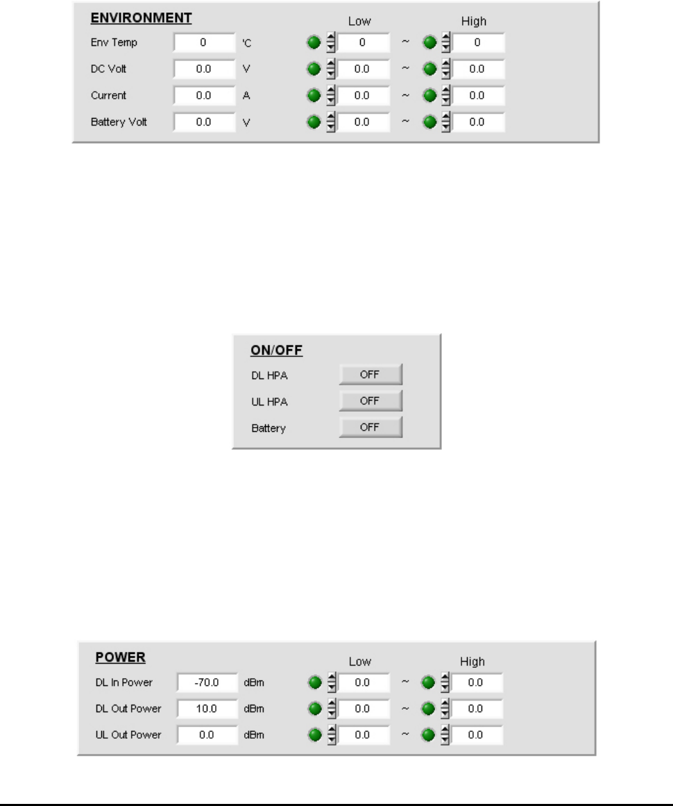
5.3.3 Circumstance Condition Control
This function enables you to set the internal temperature of the system and the upper/lower values of
the voltage and current. To change the values, you can enter the desired settings and click the “SET”
button at the upper part of the control window.
In the status mode, you can see current settings for the internal temperature, voltage, and current of
the system.
Figure 5.10 Control Window of Environmental Conditions
5.3.4 Controlling power amplifier and battery
On the “ON/OFF” window, you can control power amplifiers for each path and battery usage. With the
battery set to ‘Off’, the battery alarm will be de-activated as well.
In the “STATUS” window, you can see the current path status (ON/OFF) of the system.
Figure 5.11 Control Window of Power Amplifier and Battery
5.3.5 Controlling input/output
You can set the upper/lower values of the current input/output RF power of the up-/down-links. To
change the values, you can enter the desired settings and click the “SET” button at the upper part of
the control window.
In the status mode, you can see the current input/output settings of the up-/down-links.
Figure 5.12 Controlling Input/output
RSP-APA-002
User’s Manual
R-tron., Inc. 26/34 page
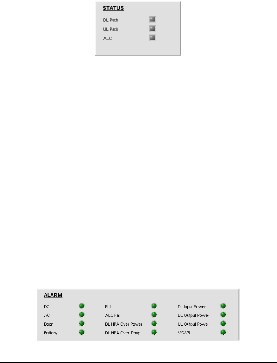
5.3.6 System status window
This window shows the status of the up-/down-link paths of the system and other status of the ALC
(de-)activation; With the Path and ALC ‘On’, the indication turns blue; with the Path and ALC ‘Off’, it
turns gray.
Figure 5.13 System status window
5.3.7 Alarm indication window
▶ DC / AC alarm : Appears when DC/AC voltage exceeds the upper/lower values set in the
“ENVIRONMENT” window.
▶ Door alarm: Appears when the housing door of the repeater is open.
▶ Battery fail alarm: This alarm stays unseen in the alarm indication window until you turns the
battery on in the “ON/OFF” window. This alarm appears when the battery voltage values
exceed the upper/lower values set in the “ENVIRONMENT” window.
▶ PLL alarm : Appears when PLL is unlocked.
▶ ALC fail alarm : This alarm appears when output during ALC operation is larger/smaller than
ALC High/Low limit values due to lack of attenuation. To clear the alarm, you need to turn off
the ALC operation mode or make the output stay in the ALC setting range.
▶ DL HPA over power alarm: Appears to protect the equipment when system output surges
abruptly. At this time, AMP will be shut down as well.
▶ DL HPA over temp. alarm: Appears when DL HPA’s internal temperature surpasses 90 degree.
▶ DL input power alarm: Appears when the repeater’s DL input is out of the upper/lower values
set in the “POWER” window. The alarm types include Low and High alarms.
▶ DL / UL output power alarm: Appears when the repeater’s DL input is out of the upper/lower
values set in the “POWER” window. The alarm types include Low and High alarms.
▶ VSWR alarm: Appears when the reflected wave of output compared to input exceeds the
setting range of the VSWR Limit (1:3) or antenna VSWR and Feeder Cable VSWR are faulty.
Figure 5.14 ALARM Indication Window
RSP-APA-002
User’s Manual
R-tron., Inc. 27/34 page
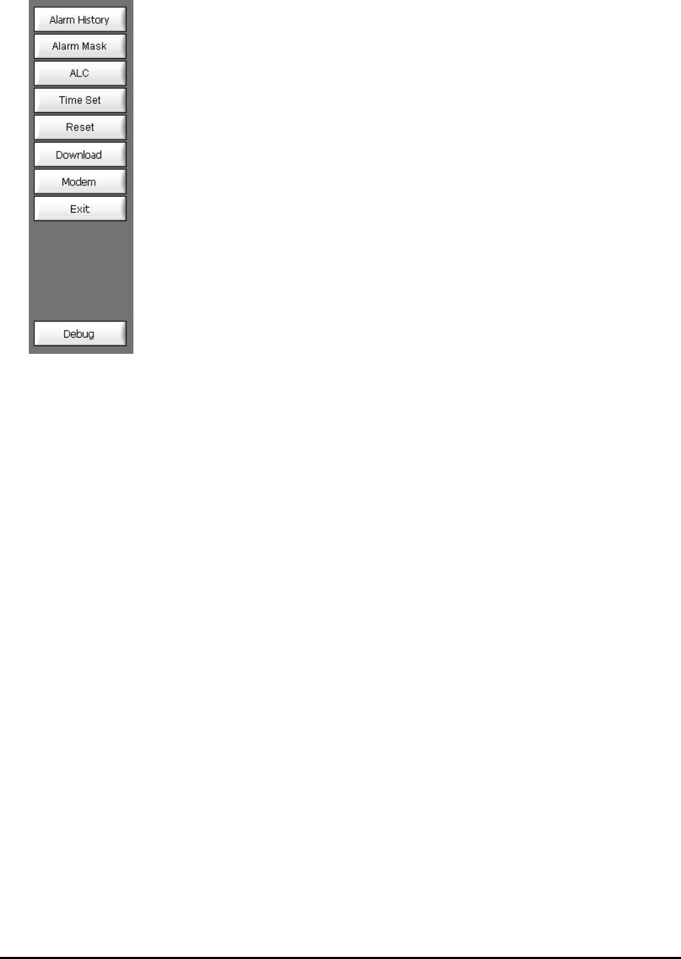
5.3.8 Menu selection window
▶ Alarm history: Shows details of alarms generated from the system
▶ Alarm Mask: Lets you select the alarms you want to use.
▶ ALC: Keeps repeater output at a certain level.
▶ Time Set: Lets you set the time on GUI and on PC.
▶ Reset: Lets you reboot the repeater MCU.
▶ Download: Lets you upgrade MCU when the firmware is upgraded.
▶ Modem: Shows default settings required for communication with wireless
modems, along with other basic settings you need to be aware of.
▶ Exit: Lets you close the GUI program.
▶ Debug: Shows communication status for repeater MCU and GUI.
Figure 5.15 Menu Selection Window
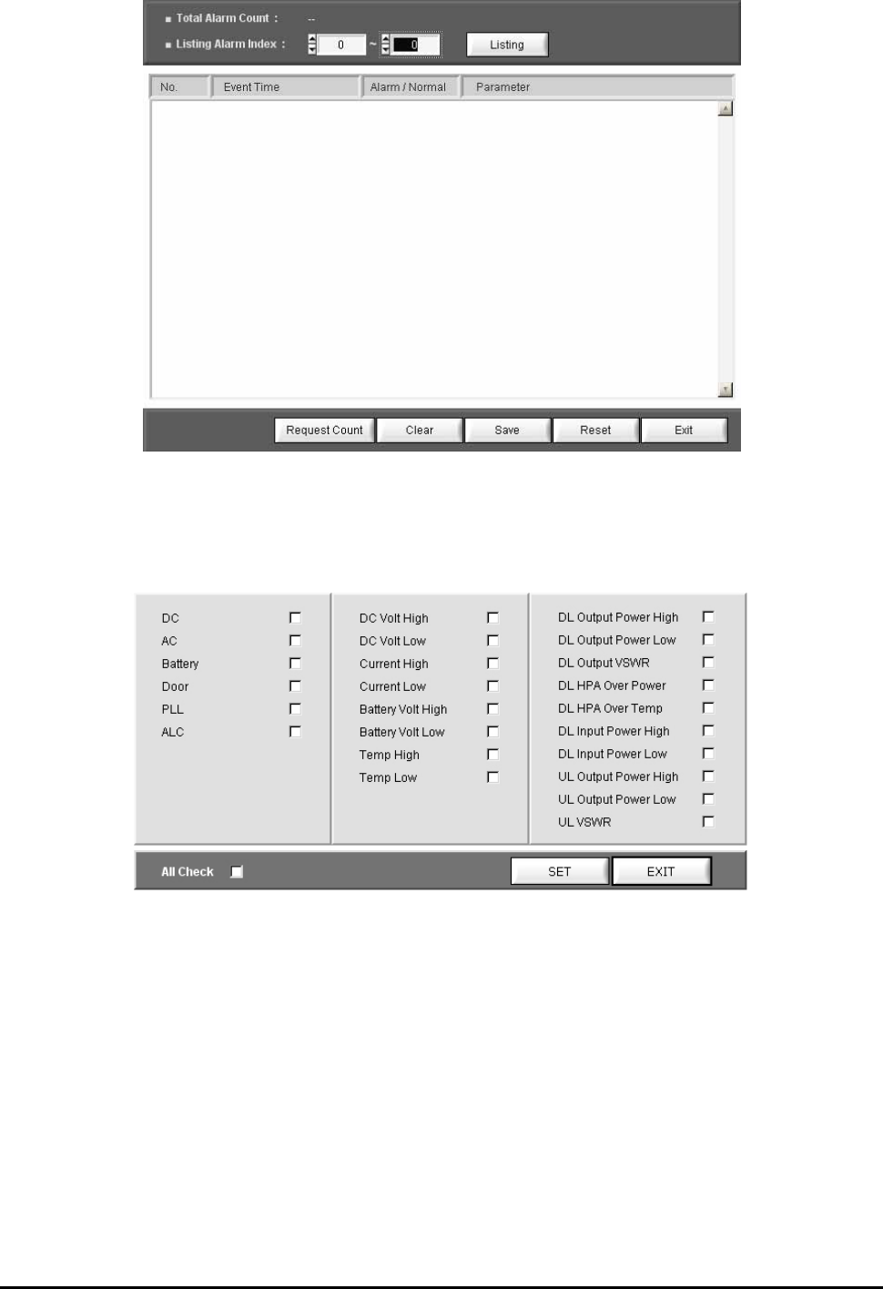
5.3.8.1 Alarm History
This window shows details on alarms stored in the system.
▶ Total Alarm count : Indicates the number of alarms stored in the current MCU. Each count
refers to alarm(s) occurring in the same timeframe. The number can be up to 250.
▶ Listing Alarm index : Lets you set the number of alarms seen on the screen. When you set a
desired number and press the ‘listing’ button, the screen will show related alarms.
▶ Clear : Deletes alarms from the screen. When you press the Clear button, alarms will not be
deleted from the MCU.
▶ Save : Stores the alarm history seen on the screen.
▶ Reset : Deletes all and every alarm from the current screen and the MCU alike.
▶ Exit : Closes the alarm history window.
RSP-APA-002
User’s Manual
R-tron., Inc. 28/34 page
Figure 5.16 Alarm History Window
5.3.8.2 Alarm Mask
This function enables you not to display frequently-made/unnecessary alarms with masking.
Figure 5.17 Alarm Mask Window
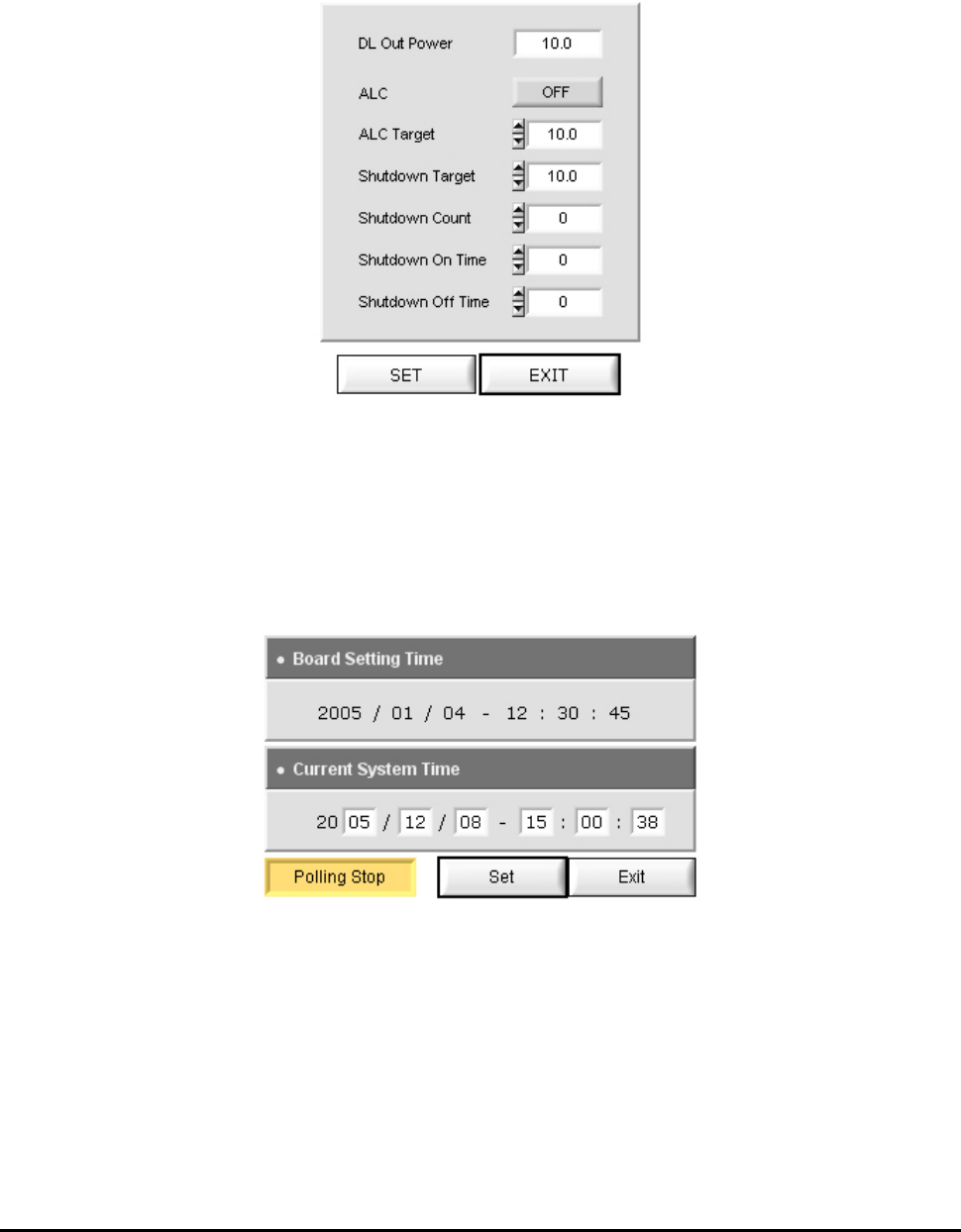
5.3.8.3 ALC (Auto Level Control) Setting
This function lets you control ALC settings and the ON/OFF status. To change a setting, you need to
enter a value and click the SET button at the lower part of the Control Window.
▶ If the ALC gets activated with system output exceeding ALC Target values, you need to use the
USER ATT to adjust the output to meet the range of the upper settings. If the output exceeds
the Attenuation range (30dB), the ALC FAIL alarm will occur. If the system output exceeds the
Shutdown Target value due to lack of attenuation, then the ASD (Auto Shut Down) will be
activated.
If output exceeds the Shutdown target values and makes the repeater shut down, the repeater
RSP-APA-002
User’s Manual
R-tron., Inc. 29/34 page
goes back to the active status after the ‘Shutdown-on’ time. If the output of the repeater is
higher than the set target value, the repeater will be de-activated again after the set ‘Shutdown-
off’ time.
The repeater repeats the process by the Shutdown count. If the output of the repeater still
exceeds the target value after the repetitive work, the repeater will turn completely off.
Figure 5.18 ALC Setting window
5.3.8.4 Time set
When you press the Time set button at the menu window, the window seen in Figure 5.19 appears.
When you click the Set button in the window, MCU automatically reads the time of the PC for time
setting. The set time appears on the RTC Time on the SYSTEM window [See the Figure 5.8].
Figure 5.19 Time set window
5.3.8.5 Reset
This function clears communication status, rebooting the MCU. When you press the Reset button,
current communication status is reset. It leads to MCU rebooting and then resets the communication
status. Then, the information on the current system is displayed on the screen.
RSP-APA-002
User’s Manual
R-tron., Inc. 30/34 page
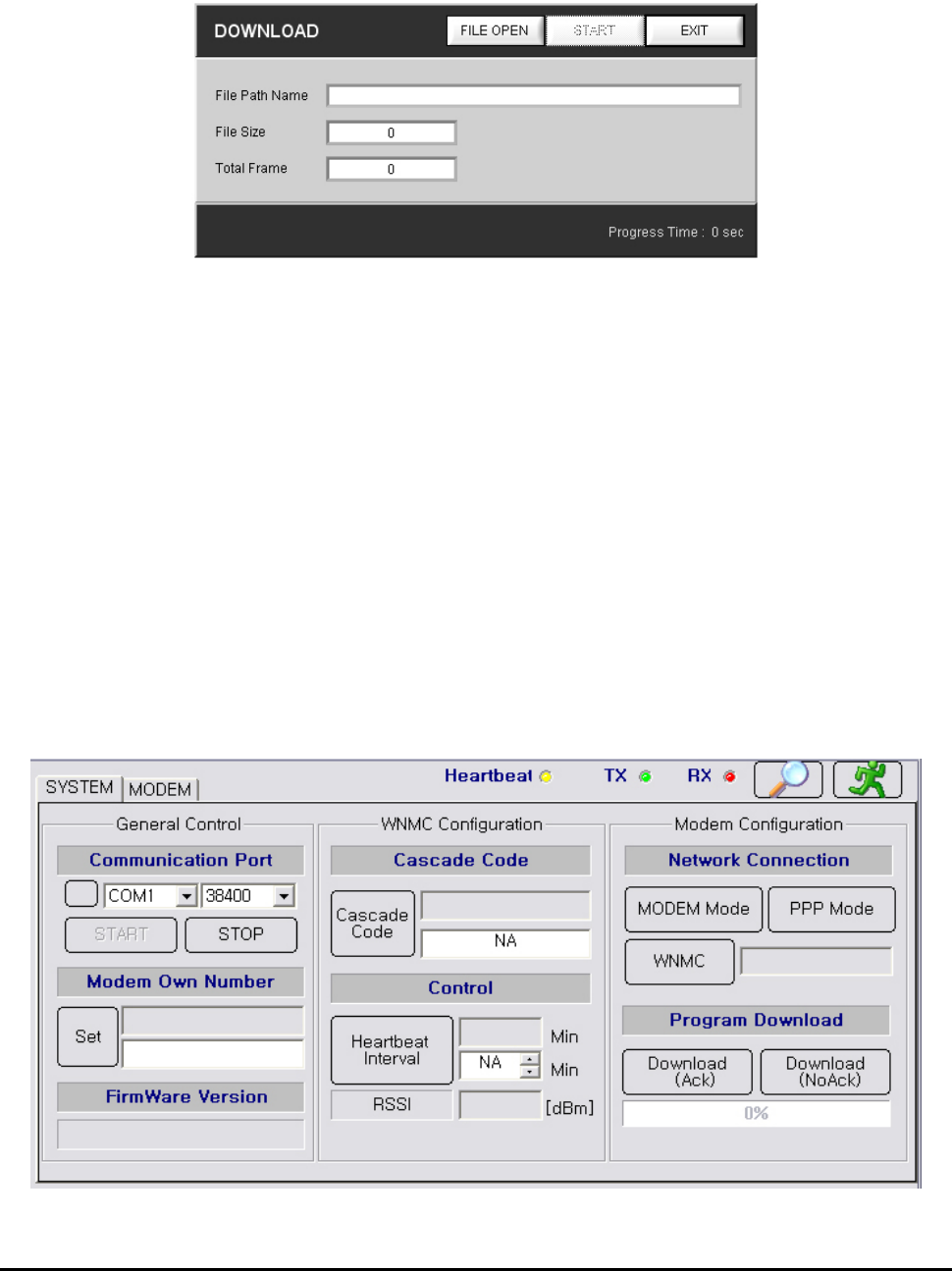
5.3.8.6 Download
When the firmware is upgraded, you can download a new firmware program to the MCU.
Downloaded files should be in Binary code.
Figure 5.20 Downloading window
Ex) Downloading Firmware
① When you click the Download at the menu window, the window seen in Figure 5.20 appears.
② Click the File to open in the Download window.
③ Click a file to be upgraded.
④ If a desired file is selected in the “File Path Name”, you can press the Start button for upgrade.
⑤ After the upgrade, you can click the Exit button to complete the downloading.
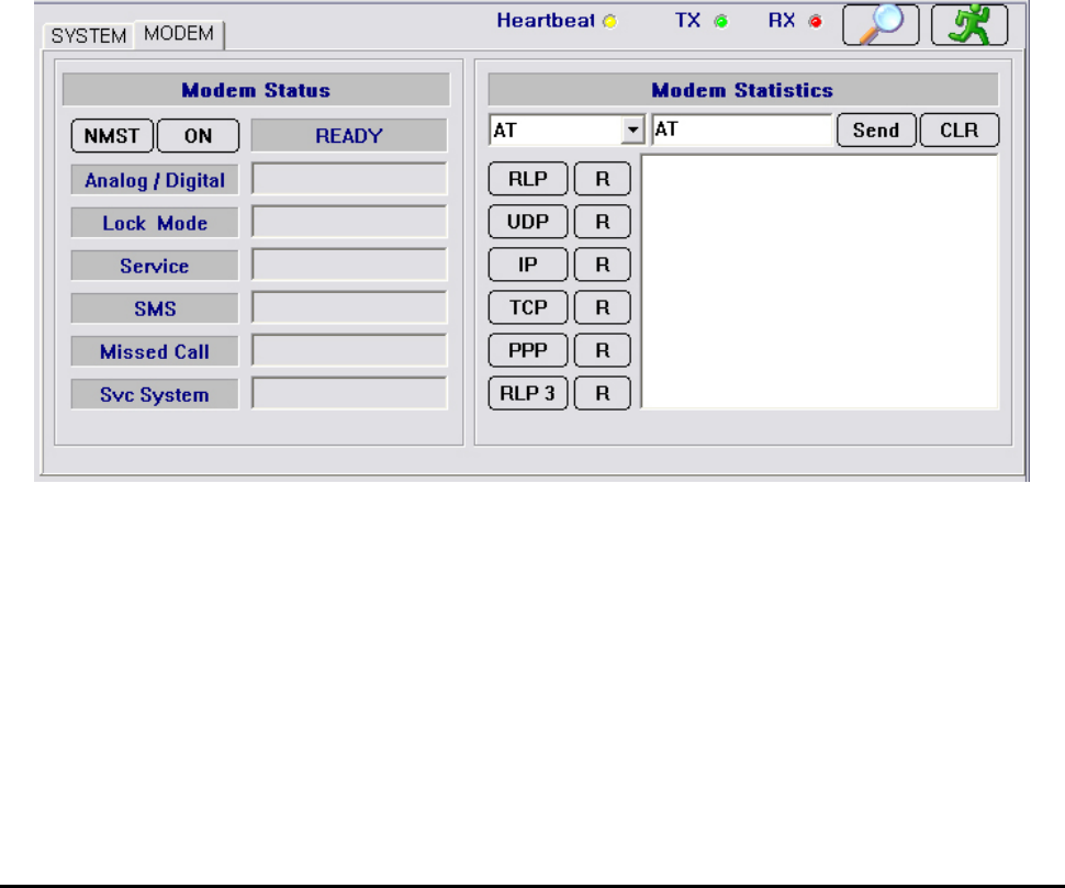
5.3.8.7 Modem
This window shows the basic settings required for communication with wireless modems and other
essential information for your reference. When you click the modem button in the menu window, the
modem system window seen in Figure 5.21 appears.
Figure 5.21 Modem System Window

RSP-APA-002
User’s Manual
R-tron., Inc. 31/34 page
1. Modem system window
▶ General control
- Communication Port : Connects MCU to the modem port. You can refer to the same settings
as those in the main GUI.
- Modem own number : Refers to the modem number, with which you can call using a modem.
- Firmware version : Refers to the version of currently used software.
▶ WNMC configuration
- Cascade code : Refers to the ID designated by operator where the repeater is installed. The
ID is composed of ten-digit characters and figures. It may appear in the following form:
XX##YY$$$$
① XX : First two-digit characters showing the installation site of the repeater.
If the repeater is installed in Boston, XX is seen as ‘BS’.
② ## : Shows whether the repeater is installed inside/outside of a building: In Building
System (Indoor type)/Macro System (Outdoor type).
③ YY : Shows device types (Repeater/cell site).
If the system is found as repeater, YY is ‘XR’; if it is a cell site, YY is ‘XC’.
④ $$$$ : Refers to integers (1 ~ 9,999) indicating the number of repeaters installed in XX.
If 24 repeaters are installed in Boston (BS), $$$$ is ‘24’.
▶ Control
The Control window is to set the periodic interval of the Heartbeat. This function lets you set
the time interval of the Heartbeat to 3 ~ 59 minutes.
▶ Modem Configuration
- Network Connection :
① Modem mode : This button lets you see the modem status. When you press the button,
the Modem Status window, the Modem Configuration window, the Modem Statistics
window, and the Modem Status window are activated. With the [NMST] button in the
Modem Status window, you can see modem status.
② PPP mode : Stands for Point to Point Protocol, which helps set connection between the
MCU and WNMC. PPP connection is automatically set. Facing connection failure, MCU
retries until the connection is successful. When PPP is fully set, the Modem Status window,
the Modem Configuration window, and the AT Command window are automatically de-
activated.
③ WNMC : This button lets you clear PPP connection. You can see whether PPP is
connected/disconnected depending on the icon color of the WNMC button. You can see the
connection status in the window next to the WNMC button. You can have access to the PPP
RSP-APA-002
User’s Manual
R-tron., Inc. 32/34 page
and verify the ‘Disconnected’ status and press the “WNMC” button. At this time, you need to
check if the status window next to the “WNMC” button is changed: Disconnected ->calling->
PPP Connected. If the connection fails to be set in 60 seconds, the status will be
‘Disconnected’ due to timeout. In this case, you can press the “WNMC”button again to
set the connection. With PPP set, MCU is connected to the Internet, enabling SNMP Trap
messages to be sent to WNMC whenever alarms and Heartbeats occur.
- Program Download : Lets you download a new firmware version to the MCU when firmware is
upgraded. Downloaded files should be in Binary format and downloading methods are split into
Ack and NoAck.
① Download(AcK) : Receives AcK (acknowledge messages) for each message that is
transmitted to calculate Check Sum. When errors are generated during file transmission,
the transferring will be immediately stopped. This method requires roughly one more
minute than the NoAcK method.
② Download(NoAcK) : Calculates Check Sum for each message that is transmitted when
AcK may not be received. AcK messages are received when the transmitted messages
are completely sent. This method reduces one minute to download than the Ack method.
Figure 5.22 Modem Status Window
2. Modem system window
▶ Modem status
- NMST button : Refers to AT command to report current modem status with AT + NMST
commands programmed in the button. When you press the button, modem status information
is displayed.
- Analog / Digital : Shows transferring methods of the modem (Analog/digital types). When the
modem uses analog communication method, ‘Analog’ is displayed; if it uses Digital

RSP-APA-002
User’s Manual
R-tron., Inc. 33/34 page
communication method, ‘Digital’ is displayed.
- Lock Mode : Shows whether the current modem is locked/unlocked. ‘Locked’ means the
current modem is locked; ‘Not Locked’, the modem is unlocked.
- Service : Shows whether the current modem is available for calling. ‘No Service’ means the
modem is not available; ‘In Service’ means the modem is available for you to try a call.
- SMS(Short Message Service) : Refers to the two-way wireless data-calling service according
to GSM (Global System for Mobile Communications), sending data at up to 150-byte length
between terminals. Using this service, you can send/receive messages composed of
characters and/or figures between terminals or networks. This service type includes short
message transferring, emergent message indication, date/time recording, and message
indication. SMS has two status of “None” and “Exist”:
“None”means there are no received SMS messages;
“Exist” means SMS messages have been received.
- Missed Call: Refers to the count of failed communication trials by the modem.
- Service System : Consists of three items of “Band Class”, “Band”, and “System ID”.
▶ Modem statistics
This window enables you to manually control the modem using AT commands.
Seen in the modem statistics, such protocols as RLP, TCP, UDP, PPP, IP, and RLP3 are
supported by a built-in operating system (Installed in protocol stacks including integrated RLP,
TCP, UDP, PPP, IP, RLP3, etc.) installed in MCU. Using the protocols, the modem can have
access to communication network.
RSP-APA-002
User’s Manual
R-tron., Inc. 34/34 page
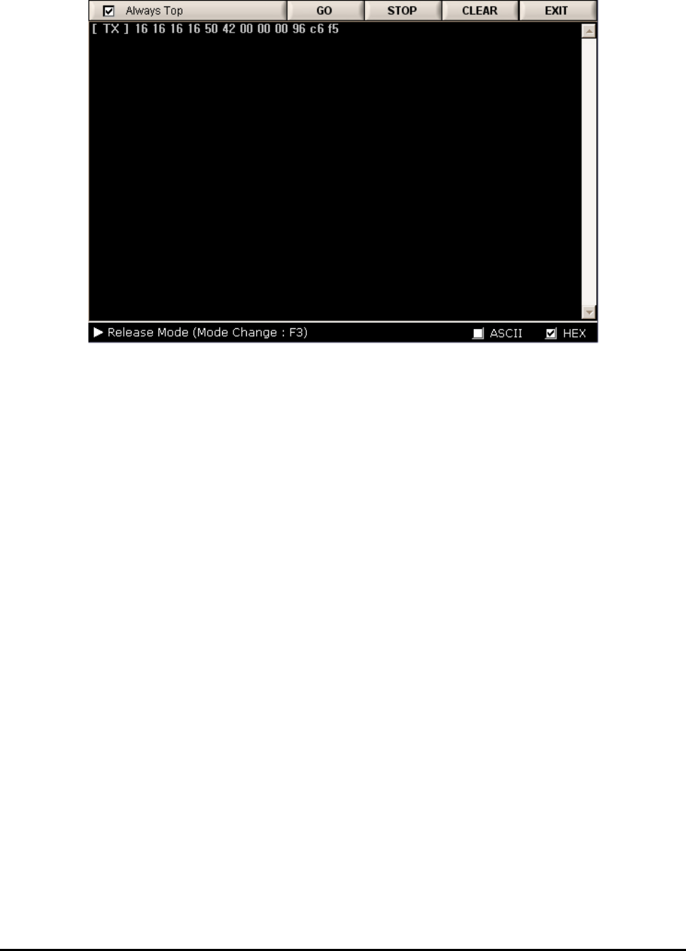
5.3.8.8 Debug
This window shows communication status for repeater MCU and GUI.
Figure 5.23 Debugging Window
5.3.8.9 Exit
This function enables you to close the GUI program. As the status of the program is stored in MCU,
you can see its latest status when executing the program later.