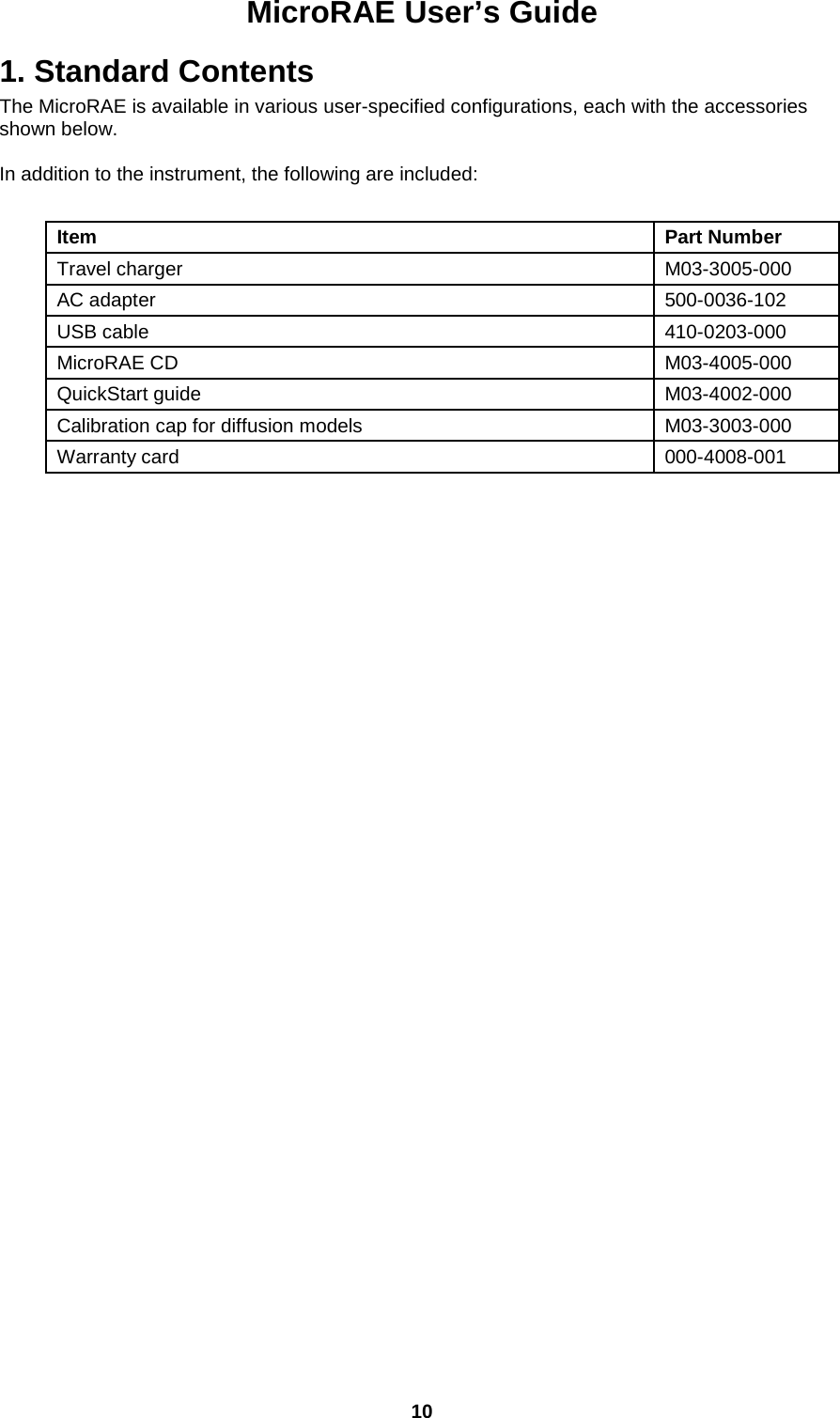
RAE Systems 2602A MICRORAE User Manual MicroRAE User s Guide
RAE Systems, Inc MICRORAE MicroRAE User s Guide
UserManual.wiki
>
RAE Systems
>
2602A User Manual
User Manual
Navigation menu
Upload a User Manual
Namespaces
Wiki Guide
HTML
PDF
Info
Views
User Manual
Discussion / Help
Navigation


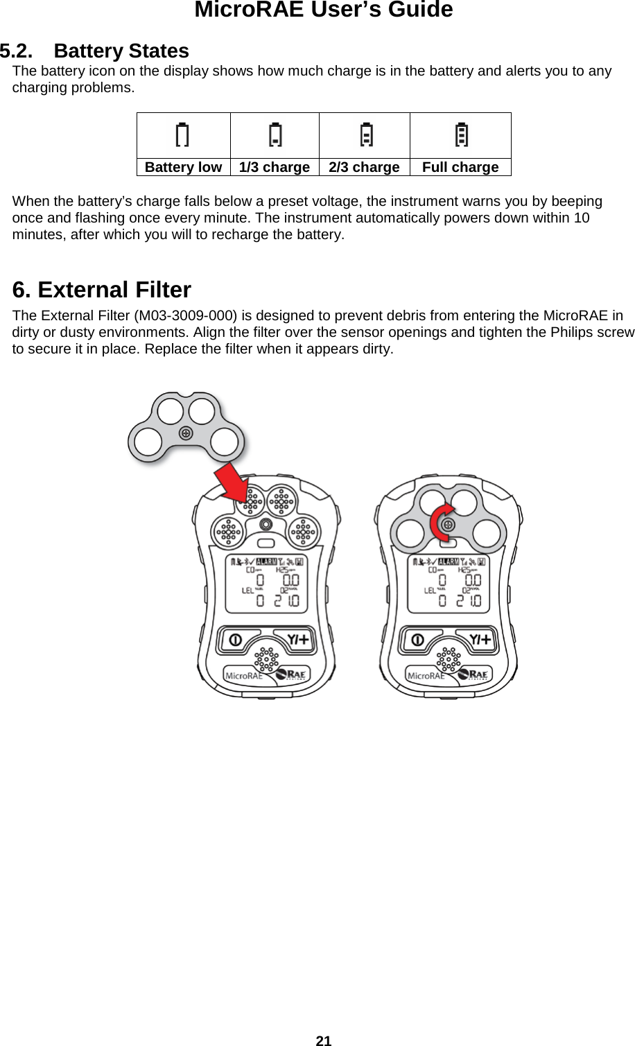
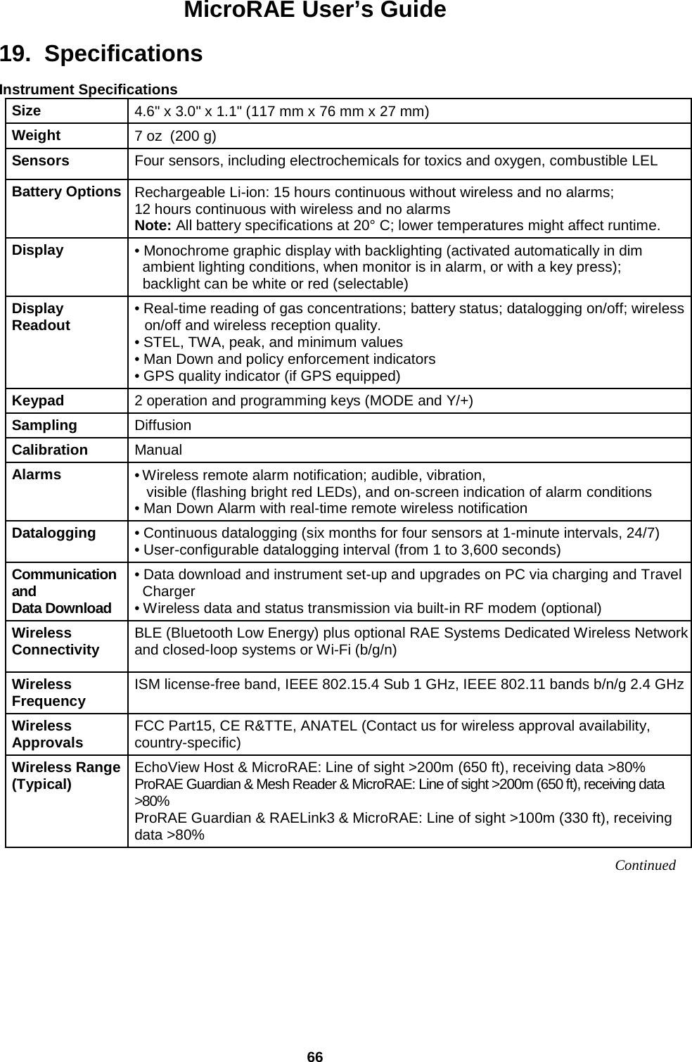
![MicroRAE User’s Guide 14 3.1.2. Keys & Interface The MicroRAE has two keys: MODE Y/+ In addition to their labeled functions, the keys labeled [MODE] and [Y/+] act as “soft keys” that control different parameters and make different selections within the instrument’s menus. From menu to menu, each key controls a different parameter or makes a different selection. In addition to the functions described above, either key can be used to manually activate display backlighting. Press a key when the backlighting is off to turn it on. 3.2. Screen Display For Various Numbers Of Active Sensors The MicroRAE can accommodate from one to four sensors. When one or more sensors is either not installed or turned off, the display only shows the installed, active sensors:](https://usermanual.wiki/RAE-Systems/2602A/User-Guide-3988977-Page-14.png)
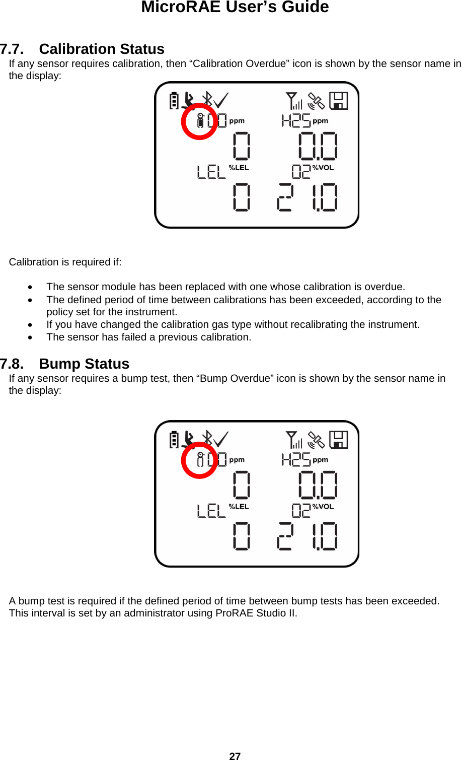
![MicroRAE User’s Guide 15 3.3. Menus The reading menus are easy to step through by pressing the [MODE] and [Y/+] key. * If the MicroRAE is Wi-Fi equipped: Wi-Fi-equipped instruments can receive up to five messages. If a message has been received by the MicroRAE, the number of messages is displayed (1 MSG, etc.). The display shows the message sequentially, cycling through the message each half-second. The Message number, “page” of the message (it automatically breaks a message across screens), and received time and date are shown. Up to five messages can be received by the MicroRAE. Pressing [MODE] steps through the messages. When “Exit” is shown, press [Y/+] to return to the Main Display. Note: In most cases, if no buttons are pressed at any of the menu steps for 60 seconds, the instrument reverts to the main display. *](https://usermanual.wiki/RAE-Systems/2602A/User-Guide-3988977-Page-15.png)
![MicroRAE User’s Guide 16 3.4. Glance Mode If you want to check your instrument’s configuration and it is turned off, you do not have to turn it on. Press and hold [Y/+] until the screen illuminates and shows the configuration. This tells you the installed sensors: Press [Y/+] to advance through screens that tell you if the radio is on, BLE is on, GPS is on, Wi-Fi is on, etc. These change, depending on the instrument’s configuration. To exit, press [MODE], and the display shuts off. Note: If you do not press a button for 60 seconds, it turns off automatically. 3.5. Panic Alarm Press and hold [Y/+] at any time to trigger the Panic Alarm. The display shows “PANIC ALARM” and sends a message to the Location Manager or ProRAE Guardian. (Note: Use ProRAE Studio II to define information and its prioritization for viewing.) In addition, the instrument alarms (audible and visible) four times per second. The instrument also sends an emergency message to the Location Manager or ProRAE Guardian. Press [Y/+] to clear the alarm. The alarm stops and the display returns to the main reading screen. 3.6. Confidence LED You can use ProRAE Studio II to program the MicroRAE to continually provide an LED blink every 3 seconds so that you can tell without looking closely that the instrument is working.](https://usermanual.wiki/RAE-Systems/2602A/User-Guide-3988977-Page-16.png)
![MicroRAE User’s Guide 22 7. Turning The MicroRAE On And Off 7.1. Turning The MicroRAE On With the instrument turned off, press and hold the [MODE] key until the audible alarm stops, and then release. When starting up, the MicroRAE turns the backlight on and off, beeps once, blinks once, and vibrates once. A RAE Systems logo should appear first. During a normal startup, this is followed by a progression of screens that tell you the MicroRAE’s current settings. Then the MicroRAE’s main reading screen appears. It takes 45 seconds for some sensors to show a reading, so if any have not warmed up by the time the main screen is shown, you will see “- -” instead of a numerical value until the sensor provides data (if you turn a sensor off and on again, it also shows “- -” for up to 45 seconds). Then it displays instantaneous readings similar to the following screen (depending on the sensors installed) and is ready for use. Note: If the battery is completely empty, the MicroRAE shuts off. You should charge the before turning it on again. IMPORTANT! If a major error that prevents the MicroRAE from functioning is found during startup, the message “Contact Service” is shown on the display. The instrument should be shut off and serviced. 7.2. Turning The MicroRAE Off Press and hold [MODE]. A 5-second countdown to shutoff begins. You must hold your finger on the key for the entire shutoff process until the MicroRAE is powered off. Caution: The alarm is very loud. During startup, you can mute most of the sound by holding a finger over the alarm port. Do not put tape over the alarm port to permanently mute it.](https://usermanual.wiki/RAE-Systems/2602A/User-Guide-3988977-Page-22.png)
![MicroRAE User’s Guide 23 7.3. Testing Alarm Indicators Under normal-operation mode and non-alarm conditions, the buzzer, vibration alarm, LED, and backlight can be tested at any time by pressing [Y/+] once. IMPORTANT! If any alarm does not respond, check MicroRAE’s alarm settings to make sure all alarms are enabled (selected setting under Programming/Alarms/Alarm Settings should be “All Enabled”). If any alarms are enabled but not functional, the instrument should not be used. 7.4. Glance Mode Glance Mode allows you to get vital information without turning the MicroRAE on. You can check information such as the instrument’s model number, installed sensor types, etc., which may help when taking inventory of instruments and their sensors or when working with service or support personnel. Glance Mode can be enabled/disabled via ProRAE Studio II. 7.4.1 Enter Glance Mode Note: The instrument must be configured so that Glance Mode is turned on (the default mode is “On”). This can be done in ProRAE Studio II. With the MicroRAE turned off, press and hold [Y/+] to enter Glance Mode. The feature is latched, meaning that it runs even after you release the [Y/+] key. If you see the message “GLANCE DISABLED,” you must configure the instrument to use Glance Mode. If Glance Mode is enabled, the first screen is displayed. After releasing [Y/+], other screens release, other screens can be displayed by pressing the [Y/+] Key. In ProRAE Studio II, Glance Mode can be enabled or disabled by checking or unchecking the box labeled “Enable Glance Mode.”](https://usermanual.wiki/RAE-Systems/2602A/User-Guide-3988977-Page-23.png)
![MicroRAE User’s Guide 24 7.4.2 Screens Every screen displayed in sequence as configuration. Press [Y/+] to advance to the next screen. Press [MODE] to exit Glance Mode and turn the instrument off. The screens are shown in sequence. 7.4.3 Exit Glance Mode MicroRAE exits Glance Mode and turns off when you press the [MODE] key. In addition, if you do not press either key in 60 seconds, the MicroRAE automatically exits Glance Mode. 7.5. Comfort Beep A Comfort Beep is a single beep of the audible alarm at 60-second intervals that provides a reminder that the MicroRAE that it is functioning. It can be turned on or off. 7.6. Man Down Alarm The Man Down Alarm is a critical and potentially lifesaving safety feature of every MicroRAE. The Man Down Alarm is based on the premise that if the instrument is motionless when it is not supposed to be, something wrong may be happening to its user. If that is the case, the MicroRAE not only goes into alarm locally on the instrument, but also remotely, over a wireless network, to notify people in the vicinity, as well as remote safety officers at a command center, that a person is down, so that help can be dispatched quickly. Note: Remote notification requires wireless connection to a network. Whenever the Man Down feature is on, the main screen displays a Man Down icon along the top to indicate it is active: IMPORTANT! When gas alarm conditions exist at the same time as the Man Down alarm is activated, the pre-alarm stage is skipped, and the instrument goes straight into Super Alarm (gas and Man Down) with four beeps/flashes per second. When the Man Down feature is on and there is no gas alarm, the MicroRAE senses that it is motionless for the amount of time set in the “Motionless Time” parameter via ProRAE Studio II. If the instrument is not moved during that time, then a pre-alarm is activated to alert the user, and shows the “OK?” screen. Pressing [Y/+] clears the alarm and returns the MicroRAE to its normal operation. Pressing [MODE] sets it into Man Down Alarm (and if wireless connectivity is enabled, a Man Down message is sent in real time to remote observers). If neither key is pressed, then after the countdown, it goes into Man Down Alarm (again sending a message to remote observers if wirelessly enabled). Settings for Man Down are available in ProRAE Studio II for: • Off/On • Motion Sensitivity (set to low, medium, high, or custom percentage) • Falldown Sensitivity (set to low, medium, or high to compensate for ambient vibration or motion) • Window (time the instrument is motionless before initiating a pre-alarm, in seconds) • Warning Time (countdown, in seconds, from pre-alarm to Man Down alarm) • Falldown Window (time after falling down is sensed, in seconds); Whenever the acceleration speed is greater than the Falldown Sensitivity, the Man Down feature is invoked.](https://usermanual.wiki/RAE-Systems/2602A/User-Guide-3988977-Page-24.png)
![MicroRAE User’s Guide 25 When the Man Down alarm is activated, the buzzer sounds and LEDs flash continuously, and a countdown begins. • If the MicroRAE’s user presses [Y/+] for “Yes” in response to the “OK?” question on the screen before the countdown reaches zero, the Man Down alarm stops and the main reading screen is displayed. • If the person does not press [Y/+] for “Yes” in response to the “OK?” question on the screen before the countdown reaches zero, the Man Down alarm is sounded and LEDs flash continuously. • If the person presses [MODE] during the countdown, answering the “OK?” question by pressing [MODE] for “No,” the Man Down alarm starts. If wireless connectivity is enabled, and the MicroRAE is connected to a network, a Man Down message is also sent to remote observers. IMPORTANT! When using the Travel Charger or Truck Mount to charge a MicroRAE, the Man Down alarm is automatically disabled so that the instrument does not go into Man Down alarm because of inactivity. This requires no changes to the instrument’s settings. Please note that Travel Chargers with a serial number lower than M0320001U5 and Truck Mounts with serial numbers lower than M035000170 do not support this feature. It is also recommended that older MicroRAE instruments have their firmware upgraded to version 1.10 or higher. 7.6.1 Parameter Settings And Sequence Of Events When a fall is sensed, as determined by the Motion Sensitivity and Falldown Sensitivity settings, the Falldown Window starts. If motion resumes, then the instrument resets itself and is ready for the next fall or motionless period. 7.6.1.1. Parameters Configured By ProRAE Studio II Index Parameter Default Value Range 1 Window time 30 seconds 30 to 90 seconds 2 Warning time 30 seconds 30 to 180 seconds 3 Falldown Window time 180 seconds 0* to approximately 1,000 seconds 4 Motion Sensitivity Medium Low (7%) Medium (37%), High (63%), Custom 5 Fall Sensitivity Medium Low (33%), Medium (67%), High (100%), Custom * If the Falldown Window value is set to “0,” the Man Down algorithm focuses only on motionless behavior. If the Falldown Window value is not set to zero, the algorithm uses acceleration to trigger its function. If acceleration is sensed, and motion does not resume, then the Warning Time starts. During this period, the instrument waits for motion. If no motion occurs by the end of the Warning Time, the Window period is entered. During that time, the display shows the “Are You OK?” message. The buzzer sounds and LEDs flash continuously, and a countdown begins. • If the MicroRAE’s user presses [Y/+] for “Yes” in response to the “Are You OK?” question on the screen before the countdown reaches zero, the Man Down alarm stops and the main reading screen is displayed.](https://usermanual.wiki/RAE-Systems/2602A/User-Guide-3988977-Page-25.png)
![MicroRAE User’s Guide 26 • If the person does not press [Y/+] for “Yes” in response to the “Are You OK?” question on the screen before the countdown reaches zero, the Man Down alarm is sounded and LEDs flash continuously. • If the person presses [MODE] for “No” during the countdown, the Man Down alarm starts. If wireless connectivity is enabled, and the MicroRAE is connected to a network, a Man Down message is also sent to remote observers. 7.6.1.2. Turn Man Down On Or Off Turn on the Man Down feature, or turn it off, using ProRAE Studio II. 7.6.1.3. Set The Sensitivity Individual sensitivity settings for Motion (acceleration) and Falldown allow for customization to individuals or activities. Default values are set at the factory, but it can be helpful to try other settings in order to customize an instrument’s response. 7.6.1.4. Set The Times Once a trigger occurs, there is a time before a warning is displayed and when the Man Down alarm is initiated. 7.6.1.5. Upload Settings To The MicroRAE When any changes to Man Down (or any other) settings are made in ProRAE Studio II, you must upload them to the instrument in order for them to be used. Click the “Upload all settings” button.](https://usermanual.wiki/RAE-Systems/2602A/User-Guide-3988977-Page-26.png)
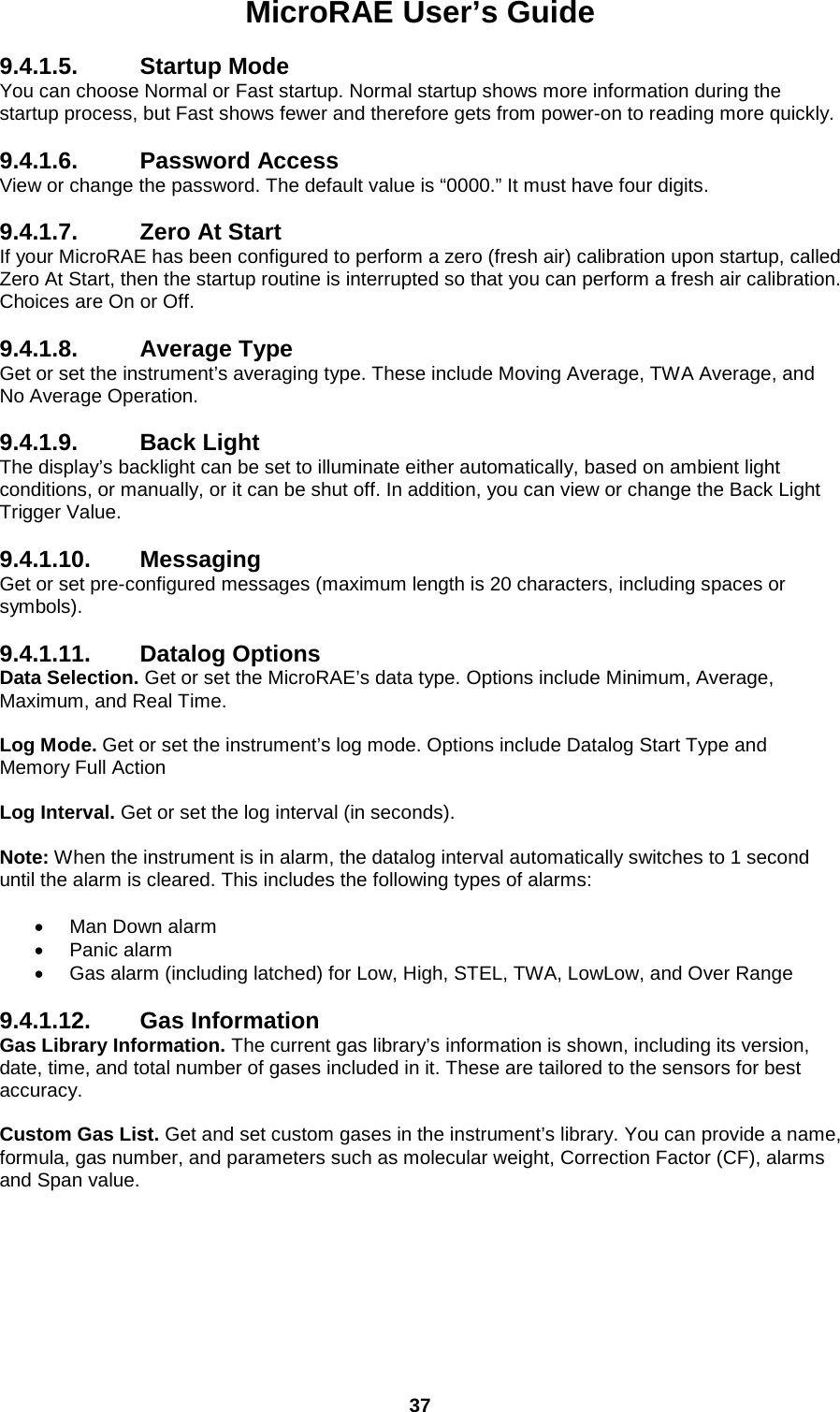
![MicroRAE User’s Guide 28 8. Modes Of Operation The MicroRAE has two user modes, selectable through ProRAE Studio II. 8.1. Basic User Mode In Basic User Mode, some restrictions are applied, including password protection that guards against entering Programming Mode by unauthorized personnel. 8.2. Advanced User Mode In Advanced User Mode, there are no access restrictions (you do not need a password), and the MicroRAE provides the indications and data you need most for typical monitoring applications. 9. Programming The menu in Programming Mode is to adjust many of the MicroRAE’s settings, calibrate sensors, and initiate communication with a computer. It has the following submenus: • Calibration • Sensor On/Off • Clear Datalog • Monitor Setup • Set Radio (Wireless) Note: Some settings are only visible and can only be changed in ProRAE Studio II. This requires connecting the instrument to a computer running ProRAE Studio II and having administrative privileges. For a list of which parameters can be set in Programming Mode on the MicroRAE, in ProRAE Studio II, or both, refer to “Editing Features” on page 64. 9.1. Enter Programming In Basic Mode 1. To enter Programming Mode, press and hold [MODE] and [Y/+] until you see the Password screen. 2. Input the 4-digit password: • Increase the number from 0 through 9 by pressing [Y/+]. • Step from digit to digit using [MODE]. • After inputting the password’s four digits, advance to “?” • Press [Y/+] to register the password and enter Programming Mode. If you receive the message “PASS ERR RETRY?” press [Y/+] to re-enter the password. Otherwise, press [MODE] to return to the main screen. If you make a mistake, you can cycle through the digits by pressing [MODE] and then using [Y/+] to change the number in each position. Note: The default password is 0000. Note: The password screen only appears when you enter the Programming Mode the first time after turning the instrument on in Basic Mode. If you have input the correct password, you do not have to input it again to enter Programming Mode until you turn the instrument off and on again.](https://usermanual.wiki/RAE-Systems/2602A/User-Guide-3988977-Page-28.png)
![MicroRAE User’s Guide 29 Once you enter Programming Mode, the Calibration screen is shown. Press [MODE] to step through the programming screens. 9.2. Enter Programming In Advanced Mode To enter Programming Mode, press and hold [MODE] and [Y/+] until you see the Calibration screen. No password is necessary in Advanced Mode. Note: Some parameters can only be viewed or changed in ProRAE Studio II. 9.3. Menus And Submenus In Programming Mode, menus and submenus are organized as shown here: Calibration Sensor On/Off Clear Datalog Monitor Setup Set Radio Single Bump Sensor 1 On/Off GPS On/Off* BLE On/Off Single Zero Sensor 2 On/Off Set Site ID Wi-Fi On/Off** Single Span Sensor 3 On/Off Set User ID Sent History** Multi Bump Sensor 4 On/Off Mesh Roaming Enable*** Fresh Air Cal Radio On/Off*** Multi Span Set PAN ID**** Exit Set Channel**** Join Network**** Factory Reset**** Exit * GPS-equipped version only. ** Wi-Fi-equipped version only. *** Mesh Wirelessly equipped version only. **** Only available if Roaming is turned off.](https://usermanual.wiki/RAE-Systems/2602A/User-Guide-3988977-Page-29.png)
![MicroRAE User’s Guide 30 9.3.1. Calibration Use this menu to perform zero or span calibration for one or more sensors, and change the gas concentration value assumed to be used in span calibration, as well as zero calibration and calibration reference gas. Refer to “Calibration And Testing” on page 41 for guidance on setting up the instrument for calibration. 9.3.1.1. Single Bump You can perform a separate bump test on each individual sensor. The active sensors’ names are shown in a list. Press [MODE] to highlight the sensor you want to bump test, and then press [Y/+] to select it. When the Apply Gas screen is shown, connect the calibration gas to the instrument, and start the bump test by pressing [Y/+]. If you do not want to perform a single bump test, press [MODE] to quit. Note: You can abort a bump test by pressing [MODE] once testing has started. When the Multi Bump test is done, a screen is shown, with the sensor names and either “Pass” or “Fail” shown next to them. 9.3.1.2. Single Zero This allows you to perform zero (fresh air) calibration on individual sensors. For most applications, the instrument should be zero calibrated in clean ambient air with 20.9% oxygen (02). For more precise low 02 percentage accuracy, and after a new 02 sensor is put into the instrument, zeroing should be performed with nitrogen (N2). A zero calibration should precede a span calibration. The active sensors’ names are shown in a list. Press [MODE] to highlight the sensor you want to zero calibrate, and then press [Y/+] to select it. When the Zero Calibration screen is shown with the sensor name and its measurement unit, start the zero calibration by pressing [Y/+]. If you do not want to perform a calibration, press [MODE] to quit. Note: You can abort a zero calibration by pressing [MODE] once testing has started. When the zero calibration is done, the Calibration Results screen is shown with either “Pass” or “Fail” shown. 9.3.1.3. Single Span Instead of performing a span calibration on more than one sensor simultaneously, you can select a single sensor and perform a span calibration. The active sensors’ names are shown in a list. Press [MODE] to highlight the sensor you want to span calibrate, and then press [Y/+] to select it. When the Apply Gas screen is shown with the sensor name and its measurement unit, connect a cylinder of span gas, start its flow, and then start the span calibration by pressing [Y/+]. If you do not want to perform a span calibration, press [MODE] to quit. Note: You can abort a span calibration by pressing [MODE] once testing has started. When the span calibration is done, the Calibration Results screen is shown with either “Pass” or “Fail” shown.](https://usermanual.wiki/RAE-Systems/2602A/User-Guide-3988977-Page-30.png)
![MicroRAE User’s Guide 31 9.3.1.4. Multi Bump Depending on the configuration of your MicroRAE and the span gas you have, you can perform a bump test simultaneously on multiple sensors. The selected sensors and their values are shown on the screen. With calibration gas connected to the instrument, start a multiple bump test by pressing [Y/+]. If you do not want to perform a multiple bump test, press [MODE]. Note: You can abort a multiple bump test by pressing [MODE] once testing has started. When the Multi Bump test is done, a screen is shown, with the sensor names and either “Pass” or “Fail” shown next to them. 9.3.1.5. Fresh Air Calibration You can perform a fresh air calibration simultaneously on multiple sensors. This procedure determines the zero point of the sensor calibration curve for all the sensors that require a zero calibration. The instrument should be zero calibrated in clean ambient air with 20.9% oxygen. A fresh air calibration should precede a span calibration. The selected sensors are shown on the screen. Start a multiple zero test by pressing [Y/+]. If you do not want to perform a test, press [MODE]. Note: You can abort a multiple zero test by pressing [MODE] once testing has started. When the Multi Zero test is done, a screen labeled Calibration Results is shown, with the sensor names and either “Pass” or “Fail” shown next to them. 9.3.1.6. Multi Span Depending on the configuration of your MicroRAE and the span gas you have, you can perform a span calibration simultaneously on multiple sensors. The selected sensors and their values are shown on the screen. With calibration gas connected to the instrument and turned on, start a multiple span calibration by pressing [Y/+]. If you do not want to perform a multiple span calibration, press [MODE]. Note: You can abort a multiple span calibration by pressing [MODE] once testing has started. When the Multi Span calibration is done, a screen labeled Calibration Results is shown, with the sensor names and either “Pass” or “Fail” shown next to them. 9.3.1.7. Exit Exit to “Sensor On/Off”: Press [Y/+]. Return to the top item in the Calibration menu, “Single Bump”. Press [MODE].](https://usermanual.wiki/RAE-Systems/2602A/User-Guide-3988977-Page-31.png)
![MicroRAE User’s Guide 32 9.3.2. Sensor On/Off You can turn sensors on or off via this set of submenus. The word “ON” or “OFF” below each sensor’s name tells you its status. 1. Press [MODE] to advance through the sensors. 2. Press [Y/+] to turn a selected sensor on or off. 3. Press [MODE] until “?” is selected. 4. Press [Y/+] to save your selection and exit to “Clear Datalog”. Otherwise, to return to the first sensor, press [MODE]. 9.3.3. Clear Datalog The instrument displays a floppy disk icon to indicate that a datalog is being recorded. The instrument stores the measured gas concentration for each sensor, date and time for each measurement, Site ID, User ID, and other parameters. All data are retained (even after the unit is turned off) in non-volatile memory so that they can be downloaded at a later time to a PC. Clearing the datalog erases all data stored in the datalog. IMPORTANT! Once the datalog is cleared, the data cannot be recovered. Note: The datalog is password protected. You must enter the correct password in order to clear the datalog. 1. Enter the password (the default value is 0000). 2. Press [Y/+]. The message “Log Cleared!” appears briefly on the screen before advancing to “Monitor Setup.” 9.3.4. Monitor Setup The Monitor Setup menu provides access to settings for GPS, Site ID, and User ID. 9.3.4.1. GPS On/Off If your MicroRAE is equipped with GPS, you can turn it on or off: 1. Press [Y/+] to enter “GPS On/Off”. 2. Press [Y/+] to turn GPS on or off. 3. Press [MODE] to save your choice and advance to “Set Site ID”. 9.3.4.2. Set User ID If your MicroRAE is to be used by a specific user, it can have a uniquely named User ID (a name or numbers or combination) to help identify it in ProRAE Guardian monitoring software. The User ID must be eight alphanumeric characters. 1. Press [MODE] to advance through the characters from left to right. 2. Press [Y/+] to advance through the letters and numbers (1, 2, 3, A, B, C, etc.). 3. Press [MODE] to register your choice and advance to the next character. 4. When you are satisfied with the Site ID, press [MODE] until “?” is selected. 5. Press [Y/+]. The Site ID is saved, and you see the confirmation message “User ID Saved.” It automatically advances to “Exit.” 6. Press [Y/+] to exit to “Set Radio.” To return to the Set Site ID, press [MODE]. 9.3.4.3. Set Site ID If your MicroRAE is to be used at a specific site, it can have a uniquely named Site ID (a name or numbers or combination) to help identify it in ProRAE Guardian monitoring software. The Site ID](https://usermanual.wiki/RAE-Systems/2602A/User-Guide-3988977-Page-32.png)
![MicroRAE User’s Guide 33 must be eight characters in length, with the first four characters alphanumeric (letters and numerals) and the last four must be numerals. 1. Press [MODE] to advance through the characters from left to right. 2. Press [Y/+] to advance through the letters and numbers. 3. Press [MODE] to register your choice and advance to the next character. 4. When you are satisfied with the Site ID, press [MODE] until “?” is selected. 5. Press [Y/+]. The Site ID is saved, and you see the confirmation message “Site ID Saved.” It automatically advances to “Set User ID.” 9.3.4.4. Set Radio Depending on which (if any) radio type is installed in the MicroRAE, there are various settings that can be changed. Note: BLE (Bluetooth Low Energy) is included in all MicroRAEs. 9.3.4.5. BLE On/Off You can turn BLE in all configurations of MicroRAE, or turn Wi-Fi or Mesh Roaming (depending on how your instrument is configured) on or off via this set of submenus. 1. From “Set Radio,” press [Y/+] to advance to BLE On/Off. 2. Press [Y/+] to turn BLE on or off, or press [MODE] to advance to the next “Set Radio” screen without changing the BLE on/off status. 9.3.4.6. Wi-Fi On/Off If your MicroRAE is equipped with Wi-Fi wireless, you can turn it on or off: Press [Y/+] to toggle Wi-Fi on or off, or press [MODE] to advance to any other radio type’s on/off screen without changing the Wi-Fi on/off status. 9.3.4.7. Sent History If your MicroRAE is equipped with Wi-Fi wireless, you can view messages that have been sent from the MicroRAE (messages must be created in ProRAE Studio II and loaded into the MicroRAE): Press [Y/+] to view sent messages. If none have been sent, then “No Msg” is shown. 9.3.4.8. Roaming On/Off The Roaming function provides continuous wireless connectivity between zones, enabling users of wireless monitors to travel from one zone/work area to another without losing communication between their monitor and ProRAE Guardian. You can turn Roaming on and off in ProRAE Studio II. 1. Press [MODE] to toggle Roaming “On” or “Off.” 2. Press [MODE] to scroll to “Exit.” 3. Press [Y/+] to exit. 9.3.4.9. Radio On/Off This is only available if your MicroRAE is configured with Wi-Fi or Mesh Radio. Press [Y/+] to turn the radio on or off, or press [MODE] to advance to the next screen without changing the radio’s on/off status.](https://usermanual.wiki/RAE-Systems/2602A/User-Guide-3988977-Page-33.png)
![MicroRAE User’s Guide 34 9.3.4.10. Set PAN ID This is only available if your MicroRAE is configured with Mesh Radio. 1. Press [MODE] to advance through the numbers from left to right. 2. Press [Y/+] to advance through the numbers (1, 2, 3, etc.). 3. Press [MODE] to register your choice and advance to the next number. 4. When you are satisfied with the PAN ID, press [MODE] until “?” is selected. 5. Press [Y/+]. The PAN ID is saved, and you see the confirmation message “Apply Settings”. It automatically advances to “Apply Success”. After 1 second, it automatically advances to “Set Channel.” 9.3.4.11. Set Channel This is only available if your MicroRAE is configured with Mesh Radio. The MicroRAE and any other devices that you want to connect wirelessly must be operating on the same channel. Note: For radio modems operating at 868MHz, only channel 0 is available. For other frequencies, channels 1 through 10 are allowed. 1. Press [MODE] to advance through the numbers from left to right. 2. Press [Y/+] to advance through the numbers (1, 2, 3, etc.). 3. Press [MODE] to register your choice and advance to the next number. 4. When you are satisfied with the channel number, press [MODE] until “?” is selected. 5. Press [Y/+]. The Site ID is saved, and you see the confirmation message “Apply Settings” followed by “Apply Success”. It automatically advances to “Join Network”. 9.3.4.12. Join Network This is only available if your MicroRAE is configured with Wi-Fi or Mesh Radio. You can tell the MicroRAE to automatically join a network. The PAN ID and Channel are shown for reference (if either is incorrect, you can change it, as described above). Press [Y/+] to join or [MODE] to advance to “Interval” without making a change. Note: If Roaming is turned on, instead of a PAN ID number, you see “- - -”. Press [Y/+] to join a network. The PAN ID and channel are shown. To join, press [Y/+]. To exit to the “Factory Reset,” press [MODE]. While it is searching for a network to join, the display shows this message: If it is unsuccessful, the display shows this message: Check your other settings, as well as those of the network you are trying to join. You can press [Y/+] to retry or [MODE] to exit without joining a network.](https://usermanual.wiki/RAE-Systems/2602A/User-Guide-3988977-Page-34.png)
![MicroRAE User’s Guide 35 9.3.4.13. Factory Reset Restore all the wireless settings to their original factory defaults. Caution! Once you reset the wireless settings, you cannot retrieve any of the settings deleted by performing this reset. Press [Y/+] to initiate a factory reset. You see this screen: Reset Radio? • Press [Y/+] to reset the wireless settings. You see the message “Pls Wait” while it resets to factory settings. When it is done it shows the PAN ID and Channel. • Press [MODE] to exit. 9.3.4.14. Exit Exit to the main reading screen: Press [Y/+]. Return to the top of the “Set Radio” menu: Press [MODE].](https://usermanual.wiki/RAE-Systems/2602A/User-Guide-3988977-Page-35.png)
![MicroRAE User’s Guide 36 9.4. Parameters Accessed Through ProRAE Studio II Some parameters can be accessed through the menus in the MicroRAE, but some can only be viewed and set in ProRAE Studio II. 9.4.1. Alarm Mode You can program the MicroRAE so that there are two ways to shut off an alarm: Auto Reset When the alarm condition is no longer present, the alarm stops and resets itself. Latch The latched setting only controls alarms for High Alarm, Low Alarm, STEL Alarm, and TWA alarm. When an alarm is in “latched” mode, the alarm signal remains on even when the alarm condition is no longer present Press [Y/+] to acknowledge and reset alarm signals. 9.4.1.1. Alarm Settings You can enable/disable any combination of light (LEDs), buzzer, and vibration alarms. Settings: • All Enabled • Lights Only • Vibration Only • Buzzer Only • Buzzer & Light • Buzzer & Vibration • Vibration & Light • All Disabled 9.4.1.2. Clock Information Set the date and time manually or check the checkbox to synchronize with your PC. Date Month (MM) and Day (DD) have two digits each, while the year (YYYY) uses four digits. Time The time must be set using the 24-hour format, following hours, minutes, and seconds (HH:MM:SS). 9.4.1.3. Last Run Time (min) This read-only parameter tells how long the MicroRAE ran during its last session. 9.4.1.4. LCD Contrast (%) The display’s contrast can be increased or decreased from its default setting. You may not need to ever change the default setting, but sometimes you can optimize the display to suit extreme temperature and ambient brightness/darkness conditions. Its midpoint is 50%.](https://usermanual.wiki/RAE-Systems/2602A/User-Guide-3988977-Page-36.png)
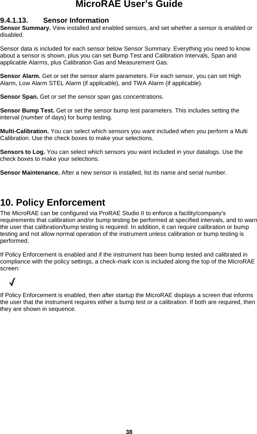
![MicroRAE User’s Guide 39 10.1. Setting Policy Enforcement You must use ProRAE Studio II to make changes to Policy Enforcement settings. Make sure the AC adapter is connected and that a USB cable is connected between the Travel Charger and a computer running ProRAE Studio II. 1. Turn on the MicroRAE. Allow the system to start up and go through its startup routine. 2. Press [MODE] until “Comm Mode?” is displayed. 3. Press [Y/+]. The screen now displays: “Ready To PC”. 4. Start ProRAE Studio II. 5. Select “Administrator.” 6. Input the password (the default is “rae”). 7. Click “OK.” 8. Click “A” (detects instruments automatically). 9. Click on the instrument’s icon when it appears to highlight it. 10. Click “Select.” 11. Click “Setup.” 12. Click “Policy Enforcement.” The Policy Enforcement pane is shown: You can select “Must Calibrate” and/or “Must Bump” and then set whether the user must perform the selected operation in order to use the instrument.](https://usermanual.wiki/RAE-Systems/2602A/User-Guide-3988977-Page-39.png)
![MicroRAE User’s Guide 40 13. Once you have made your selections in ProRAE Studio II, you must upload the changes to the instrument. Click the icon labeled “Upload current settings to the instrument.” 14. A confirmation screen is shown. Click “Yes” to perform the upload, or “No” to abort. Uploading takes a few seconds, and this progress bar is shown. You can abort the upload by clicking “Cancel.” 15. Exit ProRAE Studio II. 16. Press [MODE] on the MicroRAE to apply settings and exit Communication Mode.](https://usermanual.wiki/RAE-Systems/2602A/User-Guide-3988977-Page-40.png)
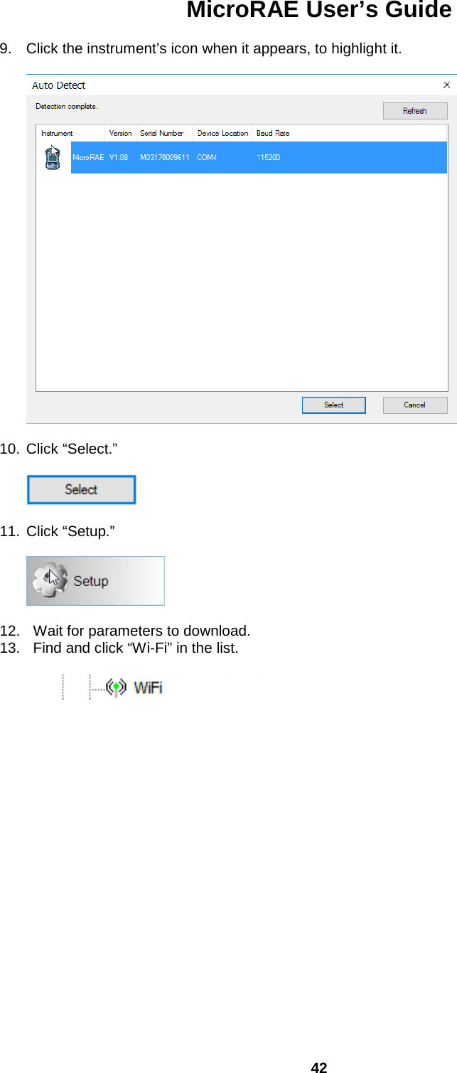
![MicroRAE User’s Guide 41 11. Setting Wi-Fi Parameters The MicroRAE’s Wi-Fi parameters for communication cannot be set directly in the instrument. They must be set in ProRAE Studio II. 11.1. Setting Wi-Fi Parameters In ProRAE Studio II Note: Before setting parameters, make sure the AC adapter is connected and that a USB cable is connected between the Travel Charger and a computer running ProRAE Studio II. (Alternatively, you can use an AutoRAE II Cradle connected to a PC running ProRAE Studio II.) 1. Turn on the MicroRAE. Allow the system to start up and go through its startup routine. 2. Press [MODE] until “Comm Mode?” is displayed. 3. Press [Y/+]. The screen now displays: “Ready To PC”. 4. Start ProRAE Studio II. 5. Once it has started, select “Administrator.” 6. Log in using your Administrator’s password (the default is “rae”). 7. Click “OK.” 8. Click “A” (for “Automatic” to detect instruments automatically).](https://usermanual.wiki/RAE-Systems/2602A/User-Guide-3988977-Page-41.png)
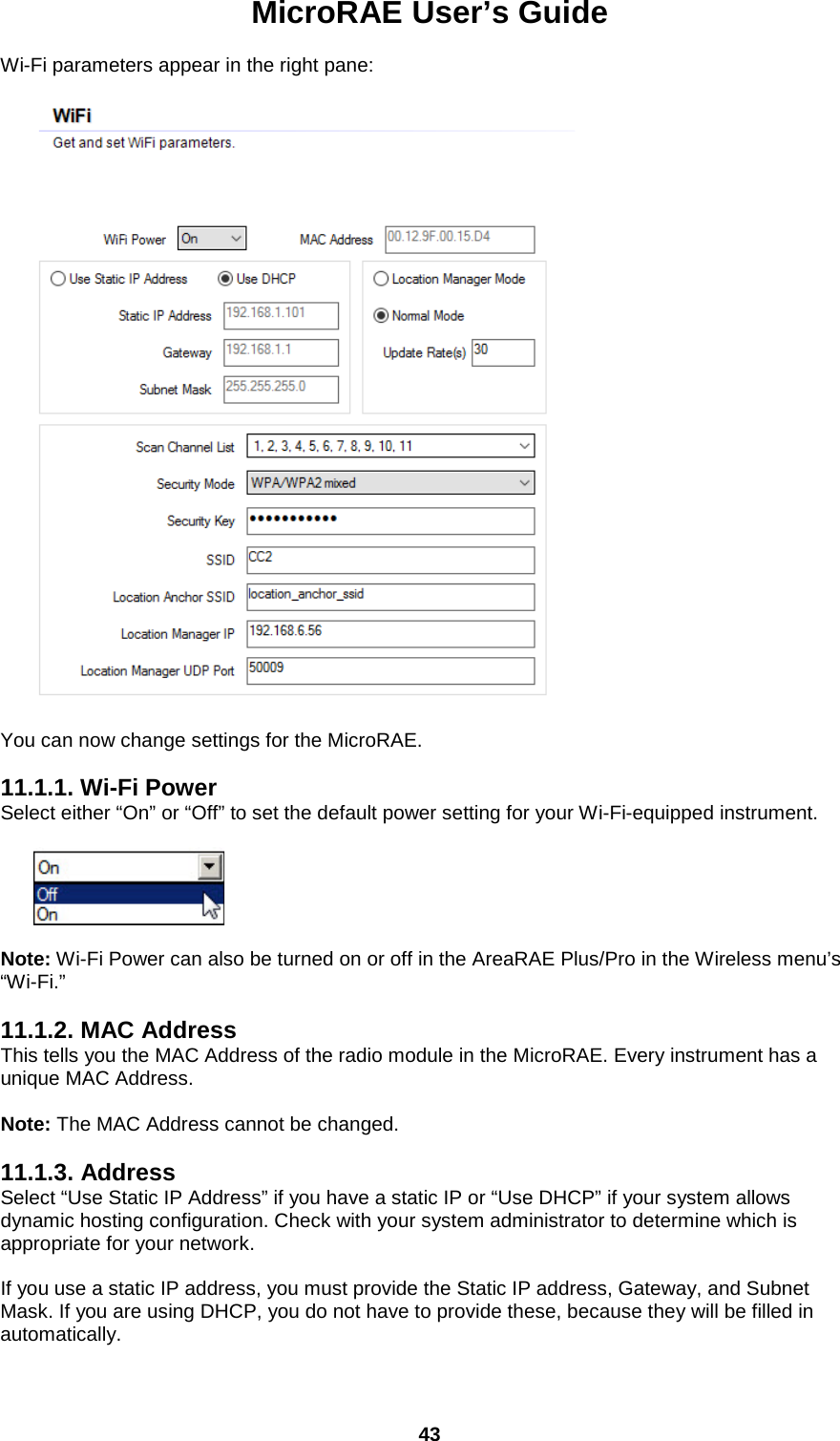
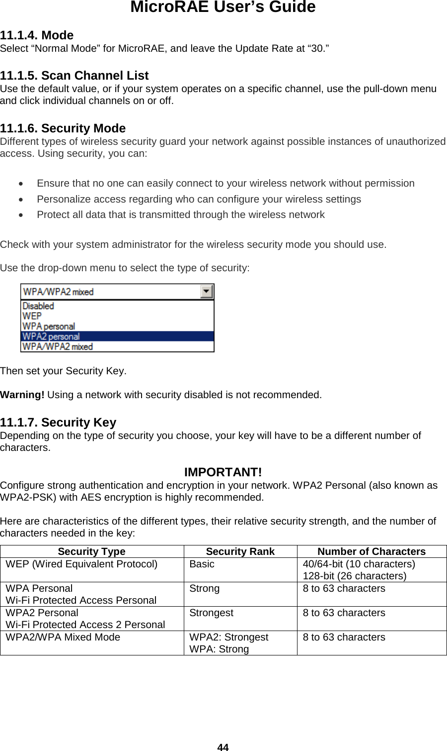
![MicroRAE User’s Guide 45 Strong Password Tips • Use a unique password. Do not reuse passwords used in other systems or for other purposes. Avoid using examples found on the Internet, in literature etc. • Use a long sequence of random characters (at least eight characters). • Use a mix of different types of characters, such as uppercase and lowercase letters, numbers, punctuation marks, etc. • To make the password easier to remember, begin with a sentence, verse, book title, line from a song etc. Omit or change certain letters. For example, use only the first few letters from each word, replace some letters with numbers or punctuation marks (for example replace all letters “a” with dots “.”), etc. • Avoid using easily guessable phrases, like names, words found in dictionaries, years, birthdays, phone numbers, etc. • Avoid using the most popular passwords, such as “123456”, “qwerty”, “password” etc. Also avoid using them even in modified formats, such as “QWErty” or “Pa55vv0rD”. • Protect the password while archived. Use trusted and properly configured password vaults for this purpose. 11.1.8. SSID The SSID (Service Set Identifier) is a case-sensitive unique identifier attached to the header of packets sent over a wireless local-area network. Each wireless network in your range will have its own SSID. Consult with your IT department for the SSID. 11.1.9. Server IP This is the destination IP address for the instrument to communicate with a computer running ProRAE Guardian. 11.1.10. Server Port The port number is distinct from any physical port on a computer such as a COM port or an I/O port address. It is a 16-bit address that exists only for the purpose of passing certain types of information to the correct location above the transport layer of the protocol stack. 11.1.11. Upload Wi-Fi Settings To The MicroRAE When you are done, click this icon to send the new settings to the instrument: 11.1.12. Exit MicroRAE’s Communications Mode When you want to exit Communications Mode, press [MODE] on the MicroRAE. The screen shows this message: Apply Settings? To apply the new settings, press [Y/+]. Otherwise, press [MODE] and exit. 11.1.13. Disconnect The MicroRAE From The PC Disconnect the MicroRAE from the PC or remove it from the AutoRAE 2 Cradle. 11.1.14. Test The MicroRAE’s Wi-Fi Operation Test the MicroRAE in your network to ensure that it communicates properly. Always do this after performing any changes to wireless parameters.](https://usermanual.wiki/RAE-Systems/2602A/User-Guide-3988977-Page-45.png)
![MicroRAE User’s Guide 47 12.1.1. Bump (Functional) Testing (Single Bump or Multi Bump) The same gas is used for a bump test as for calibration. A constant-flow regulator producing 0.5 liters per minute (1 liter per minute for HCN sensors) should be used, and the calibration adapter must be installed. The instrument must be connected to a cylinder of calibration gas with supplied tubing. 1. Turn on your MicroRAE by pressing and holding the [MODE] key, and allow the instrument to boot up fully until the main measurement screen with sensor names and readings is shown. Important! Make sure all of the instrument’s sensors have warmed up before performing a bump test. The instrument will take the time to warm up the sensors prior to enabling access to bump test menus. You can tell a sensor has warmed up if you see a reading next to it name on the display. If it has not warmed up, you see three dashes (“--”) next to it. 2. Install the calibration adapter on the MicroRAE by setting it on over the sensors and turning the knob until it is snug against the surface of the instrument. 3. Turn on the gas to initiate flow. 4. Connect the calibration adapter to the calibration gas. 5. Press Start ([Y/+] key) to start the bump test, or press [MODE] to quit. While the bump test is being performed, the readings for each sensor are shown. Once the bump test completes, pass/fail test results and readings are shown for each sensor. Important! If one or more sensors fails a bump test, be sure to calibrate those sensors. 6. The bump test is now complete. Press [MODE] to exit to the next bump or calibration type in the Calibration menu. (Press [MODE] several times until you see “Exit,” and then press [Y/+] to continue through other menu options. If all the alarms and all sensors have passed and no sensor is due for a calibration, the instrument is now ready for use.](https://usermanual.wiki/RAE-Systems/2602A/User-Guide-3988977-Page-47.png)
![MicroRAE User’s Guide 48 12.2. Zero Calibration This operation sets the zero point of the sensor calibration curve for clean air. It should be performed before other calibrations. Note: If you use a zero air cylinder, you must use the MicroRAE Calibration Adapter. Using a calibration adapter is not necessary for calibration in fresh air. 12.2.1. Zero Calibration This procedure determines zero points of most sensors. The MicroRAE should be zero-calibrated in clean air with 20.9% oxygen or with a cylinder of clean zero air. At the Calibration menu, select “Fresh Air” by pressing [Y/+] once to enter fresh air calibration. After a timer countdown, the zero calibration is done. The LCD displays the sensor names and tells you whether each calibration passed or failed, followed by the sensor readings. Note: You can abort the calibration at any time during the countdown by pressing [MODE]. 12.2.2. Single-Sensor Zero Calibration Select the sensor and then start the calibration by pressing [Y/+]. You can abort the procedure anytime by pressing [MODE].](https://usermanual.wiki/RAE-Systems/2602A/User-Guide-3988977-Page-48.png)
![MicroRAE User’s Guide 49 12.3. Span Calibration This procedure determines the second point of the sensor calibration curve for the sensor. Note: When a manual calibration is performed, the readings shown are in the equivalent units of the calibration gas, and not the measurement gas. When performing a Span calibration, the Calibration Adapter must be used for supplying calibration gas to all sensors at one time: 1. Align the Calibration Adapter’s main body with the indented area around the MicroRAE’s gas inlets. 2. Turn the knob clockwise to secure the Calibration Adapter to the instrument. 3. Connect the hose to the Calibration Adapter and to its gas source. 4. Make sure the Calibration Adapter is securely attached before starting the flow of calibration gas. (The Calibration Adapter has small grooves on its underside to allow gas to escape after passing over the sensors.) 12.3.1. Multi-Sensor Span Calibration This lets you perform a span calibration on multiple sensors simultaneously. It requires using the appropriate span gas and that the concentration labeled on the gas cylinder matches the concentration programmed in the MicroRAE. 1. Start the flow of calibration gas. 2. Attach the calibration adapter and gas to the MicroRAE. 3. Press [Y/+] to begin calibration. A countdown screen is shown. You can abort the calibration at any time during the countdown by pressing [MODE]. If the calibration reaches its conclusion, it shows the sensor names and tells you whether the calibration passed or failed, followed by the sensor readings. Note: The maximum span value for O2 is 20.8%. 12.3.2. Single-Sensor Span Calibration To perform span calibration of an individual sensor, follow these steps: 1. At the Calibration Menu, select “Single Sensor Span.” 2. Select a sensor from the list. 3. Start the flow of calibration gas. 4. Connect the calibration adapter and connect it to a source of calibration gas. 5. Verify that the displayed calibration value meets the concentration label on the gas cylinder. 6. Press [Y/+] to start calibrating. You can abort the calibration at any time during the countdown by pressing [MODE]. After a timer countdown, the span calibration is done. The LCD will display whether the calibration was successful and the reading for that calibration gas.](https://usermanual.wiki/RAE-Systems/2602A/User-Guide-3988977-Page-49.png)
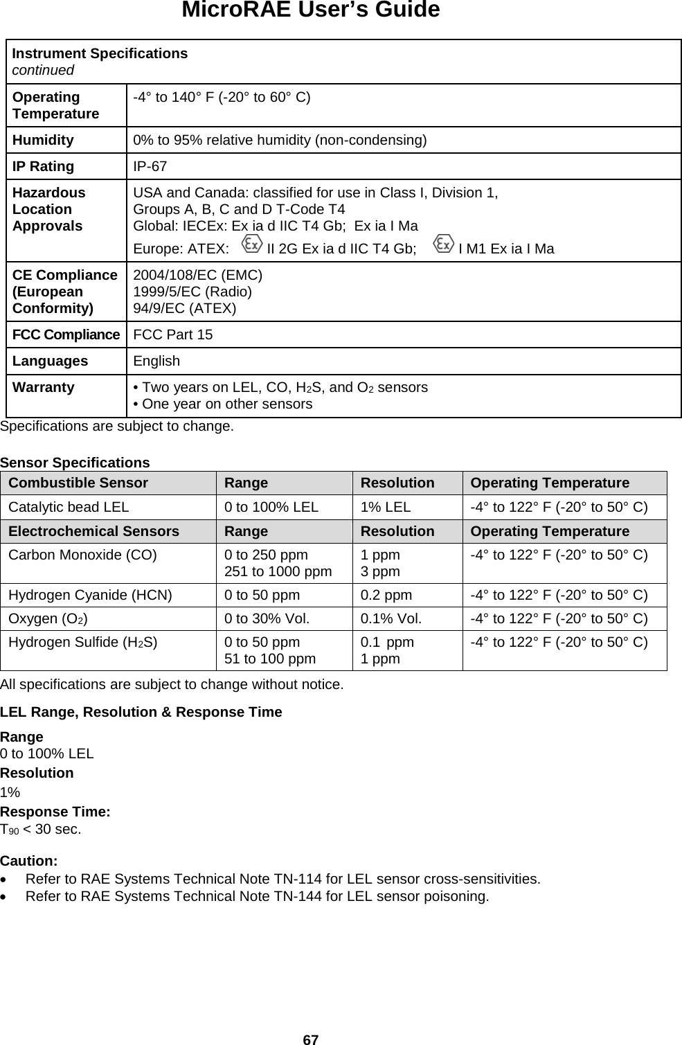
![MicroRAE User’s Guide 51 13. Datalog Transfer, Monitor Configuration, and Firmware Upgrades Via Computer Note: Basic functionality can be adjusted via the MicroRAE’s interface, but more extensive functionality and parameters can be adjusted using ProRAE Studio II software. Datalogs can be downloaded from the MicroRAE to a computer, and firmware updates can be uploaded to the MicroRAE via the USB port on the Travel Charger. Use the included Mini B USB (5-pin)-to-USB cable to connect the Travel Charger to a computer running ProRAE Studio II (version 1.10.0 or higher). 13.1. Downloading Datalogs And Performing PC-Based Instrument Configuration and Firmware Upgrades The MicroRAE communicates with a PC running ProRAE Studio II Instrument Configuration and Data Management software to download datalogs, configure the instrument, or upload new firmware. The MicroRAE must be connected to a PC through the supplied Travel Charger and must be in the PC communications mode. 1. Use the supplied PC Communications Cable (USB to mini-USB cable) to connect the Travel Charger to a PC. 2. Turn on the MicroRAE. Make sure it is running (with the main measurement screen showing). 3. Activate the PC communications mode on the MicroRAE by pressing [MODE] repeatedly, starting from the main measurement screen until you reach the “Comm Mode” screen. 4. Press [Y/+]. Measurement and datalogging stop, and the instrument is now ready to communicate with the PC. The display now says “Ready To PC”. 5. Start up the ProRAE Studio II software, enter a password, and detect the instrument following the directions provided in the ProRAE Studio II User’s Guide. 6. Follow the instructions in the ProRAE Studio II User’s Guide to download the datalog, configure the instrument settings, or update the MicroRAE’s firmware. 7. When you are done, press [MODE] to exit the PC communications mode on the MicroRAE. Note: After upgrading the MicroRAE's firmware, the instruments will turn off automatically. Mini B USB (5-Pin) to USB cable Travel Charger Mini B USB (5-Pin) port LED Power Indicator](https://usermanual.wiki/RAE-Systems/2602A/User-Guide-3988977-Page-51.png)
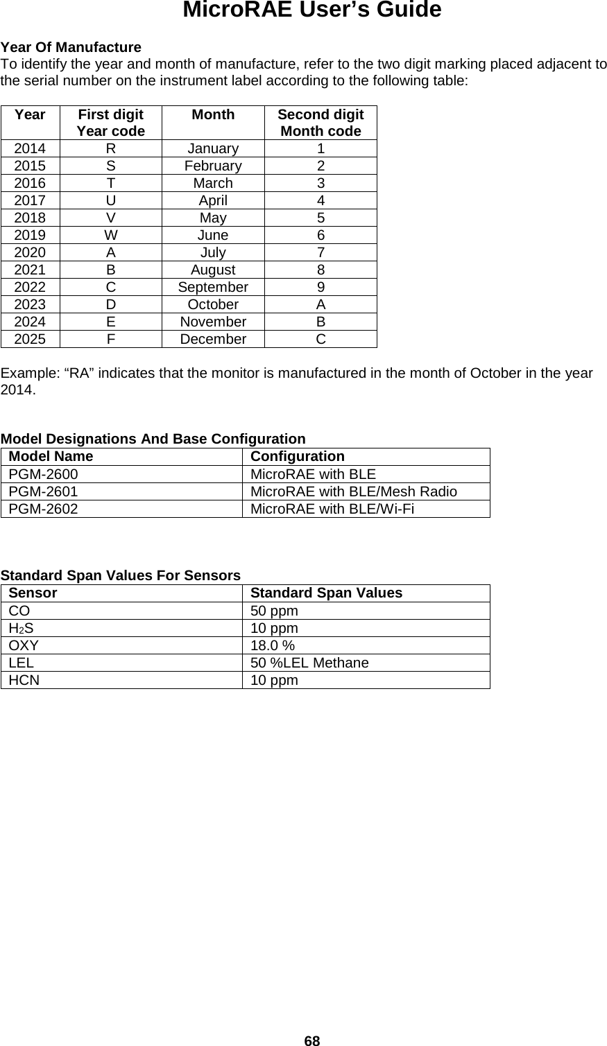
![MicroRAE User’s Guide 61 General Alarms 15.1. Manual Alarms Test Under Normal Operation Mode and non-alarm conditions, the buzzer (audible alarm), vibration, visible alarms, and backlight can all be tested anytime by pressing [Y/+]. If any alarm does not respond, connect the MicroRAE to a PC running ProRAE Studio II and check the alarm settings to make sure all alarms are enabled. If any alarms are enabled but not functional, the instrument should not be used. Contact RAE Systems Technical Support. Alarm Type Buzzer & LED Display Vibrator Reading Backlight Priority Oxygen Low Low 3 beeps/second “LOW” Oxygen sensor on display 400ms - On Highest Low Alarm 2 beeps/sec “LOW” at sensor location, ALARM icon on 400ms Blinking reading On Confidence LED flash Blinking Confidence LED for 3 seconds “OK” on display - - - GPS Offline - Blinking “GPS” icon - - - Lowest * For oxygen, “LOW Oxygen” means a concentration is lower than the low alarm limit.](https://usermanual.wiki/RAE-Systems/2602A/User-Guide-3988977-Page-61.png)
![MicroRAE User’s Guide 62 16. Troubleshooting Problem Possible Reasons & Solutions Cannot turn on power after charging the battery Reasons: Defective charging circuit. Defective battery. Solutions: Try charging the battery again. Replace battery or charger. Lost password Solutions: Call Technical Support at +1 408-952-8461 or toll-free at +1 888-723-4800 Buzzer, LED lights, and vibration motor inoperative Reasons: Buzzer and/or other alarms disabled. Bad buzzer. Solutions: Check under “Alarm Settings” in Programming Mode that buzzer and/or other alarms are not turned off. Call authorized service center. If you need replacement parts, please contact an authorized RAE Systems distributor. 17. Diagnostic Mode In Diagnostic Mode, the MicroRAE provides raw counts for sensor, battery, and other readings, as well as a list of installed sensors and information about them (expiration date, serial number, etc.). Most of these screens are useful only to service technicians. Many allow access for changing settings. The MicroRAE’s Diagnostic Mode can only be accessed at startup time. In Diagnostic Mode, MicroRAE displays readings in raw counts instead of units such as parts per million (ppm) or other units of measure. 17.1. Entering Diagnostic Mode 1. With the MicroRAE turned off, press and hold both [MODE] and [Y/+]. 2. When the display turns on and the password screen appears, release the keys. 3. Enter the 4-digit password (the password is the same as the one for the Programming Mode; the default password is 0000). • Step from one position in the four-character string to the other by pressing [MODE]. • Press [Y/+] repeatedly to select a desired number. Numbers increase from 0 to 9. • Once 9 is reached, pressing [Y/+] again “wraps” around back to 0. 4. When you are done, press [MODE] followed by [Y/+]. If you input the correct password, the instrument restarts in normal reading mode. 17.2. Exiting Diagnostic Mode 1. Turn off the MicroRAE by pressing and holding [MODE]. There will be a standard shutoff countdown. 2. When the instrument shuts off, you will be alerted. Release your finger. Note: The next time you start MicroRAE, hold only [MODE], and it will automatically start in Normal Mode.](https://usermanual.wiki/RAE-Systems/2602A/User-Guide-3988977-Page-62.png)
![MicroRAE User’s Guide 63 17.3. Navigating Diagnostic Mode Step through Diagnostic Mode by pressing [MODE]. The first screen you see is information about the product, including the serial number, firmware version, etc. Exit Diagnostic Mode at any time by shutting the instrument off (hold [MODE] for the 5-second countdown). • Instrument model name and ID number (in hexadecimal) • Serial number • Instrument firmware Version • Firmware build date • Firmware build time • Sensors Installed • Socket Raw Counts (for all installed sensors) • Zero and Span raw counts for LEL sensor • Zero and Span raw counts for O2 sensor • Air and Span raw counts for O2 sensor • Location 1 Zero and Span raw counts • Location 2 Zero and Span raw counts • LEL sensor ID and Gain (press [Y/+] to step through raw count and last calibration date and time) • O2 sensor ID and Gain (press [Y/+] to step through raw count and last calibration date and time) • Location 1ID and Gain (press [Y/+] to step through raw count and last calibration date and time) • Location 2 ID and Gain (press [Y/+] to step through raw count and last calibration date and time) • Buzzer Mode (press [Y/+] to change: 0 = silent, 1 through 7 indicates number of beeps per second) • Buzzer Frequency (press [Y/+] to change frequencies in 100 Hz increments) • Battery voltage (raw count; press [Y/+]to view VRAW and voltage) • RTC (real-time clock) shows date and time • Ambient light sensor threshold raw count (press [Y/+] to turn backlight on/off) • Backlight and Vibrator (press [Y/+] to toggle; BKL1 = white backlight, BKL2 = red backlight) • Temperature raw count and Celsius reading • Motion (shows X, Y, and Z position; press [Y/+] to change window, warning time, and threshold value) • Runtime • LCD contrast (press [Y/+] to change) • LCD Test (press [Y/+] to show entire display) • BLE (Bluetooth Low Power) power on (on/off status, press [Y/+] for MAC address) • GPS Power (if GPS is installed) • Wi-Fi (press [Y/+] to step through settings) • GPS longitude and latitude (press[Y/+] to show status and number of satellites • Mesh module firmware version and build date (press [Y/+] to show ID, PANID, Press[Y/+] to continue to show PID and channel, and press [Y/+] again to show region and radio type) • Communication – Enter communication mode with computer (press [Y/+] to enter; press [MODE] to exit)](https://usermanual.wiki/RAE-Systems/2602A/User-Guide-3988977-Page-63.png)
![MicroRAE User’s Guide 70 2. Use the supplied PC Communications Cable (USB to mini-USB cable) to connect the Travel Charger to a PC. 3. Turn on the MicroRAE. Make sure it is running (with the main measurement screen showing). 4. Activate the PC communications mode on the MicroRAE by pressing [MODE] repeatedly, starting from the main measurement screen until you reach the “Comm Mode” screen. 5. Press [Y/+]. Measurement and datalogging stop, and the instrument is now ready to communicate with the PC. The display now says “Ready To PC”. 20.3. Download And Start BLE Programmer 1. Download a file called BLE Programmer V1.0.2.zip (available at https://www.raesystems.com/customer-care/firmware-updates/ble-updater-microrae) to a computer that is connected to your smartphone via a USB cable. 2. Unzip (uncompress) the file, which creates a folder. 3. Open the folder. 4. Click on the file named “BLEProgrammer.exe”. 5. Click “Start” to start the programming: Processing begins, and this screen is shown: Note: Make sure the COM Port number is correct. If it is not, the procedure fails.](https://usermanual.wiki/RAE-Systems/2602A/User-Guide-3988977-Page-70.png)
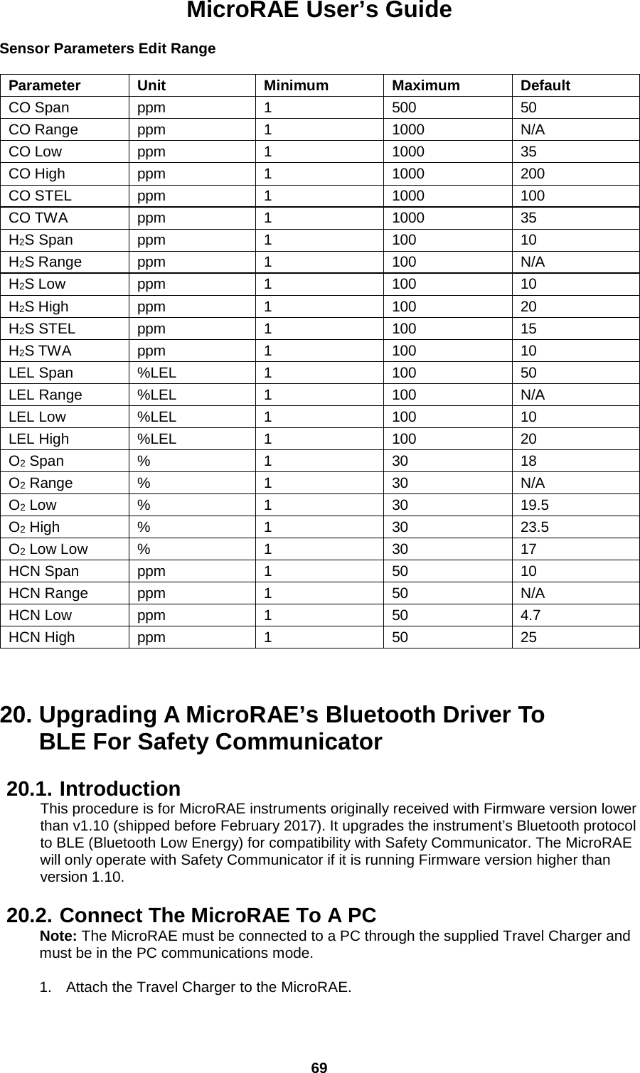
![MicroRAE User’s Guide 71 When the procedure is finished, the screen looks like this: 1. Click the “X” in the upper right corner to close the window. 2. When you are done, press [MODE] on the MicroRAE to exit the PC communications mode. Shut off the MicroRAE, and then restart it. Safety Communicator should now be able to communicate with the MicroRAE.](https://usermanual.wiki/RAE-Systems/2602A/User-Guide-3988977-Page-71.png)