RAE Systems 2602A MICRORAE User Manual MicroRAE User s Guide
RAE Systems, Inc MICRORAE MicroRAE User s Guide
User Manual
MicroRAETM
Wireless Personal Four-Gas Monitor
User’s Guide
Rev. E
June 2018
P/N M03-4001-000
IMPORTANT! BUMP TEST THE MONITOR
BEFORE EACH DAY’S USE
Prior to each day’s use, every gas detection monitor should be bump tested to confirm the
response of all sensors and activation of all alarms by exposing the monitor to a concentration of
target gas that exceeds the low alarm set point. A bump test is also recommended if the monitor
has been subjected to physical impact, liquid immersion, an Over Limit alarm event, or custody
changes, or anytime the monitor’s performance is in doubt.
To ensure greatest accuracy and safety, only bump test and calibrate in a fresh air environment.
The monitor should be calibrated every time it does not pass a bump test, but no less frequently
than every six months, depending on use and exposure to gas and contamination, and its
operational mode.
• Calibration intervals and bump test procedures may vary due to national legislation.
• Honeywell recommends using calibration gas cylinders containing the gas that is
appropriate to the sensor you are using, and in the correct concentration.
© 2018 RAE Systems by Honeywell
Product Registration
Register your product online by visiting:
http://www.raesystems.com/support/product
-registration
By registering your product, you can:
• Receive notification of product upgrades or enhancements
• Be alerted to Training classes in your area
• Take advantage of RAE Systems special offers and promotions
MicroRAE User’s Guide
Contents
1. Standard Contents ..................................................................................................................... 10
2. General Information ................................................................................................................... 11
3. User Interface ............................................................................................................................ 12
3.1. Display Overview ............................................................................................................ 12
3.1.1. Status Indicator Icons ............................................................................................ 12
3.1.2. Keys & Interface .................................................................................................... 14
3.2. Screen Display For Various Numbers Of Active Sensors .............................................. 14
3.3. Menus ............................................................................................................................. 15
3.4. Glance Mode ................................................................................................................... 16
3.5. Panic Alarm ..................................................................................................................... 16
3.6. Confidence LED .............................................................................................................. 16
4. Mesh Wireless Control And Submenus ..................................................................................... 17
5. Battery Charging ........................................................................................................................ 18
6. External Filter............................................................................................................................. 21
7. Turning The MicroRAE On And Off ........................................................................................... 22
7.1. Turning The MicroRAE On.............................................................................................. 22
7.2. Turning The MicroRAE Off.............................................................................................. 22
7.3. Testing Alarm Indicators ................................................................................................. 23
7.4. Glance Mode ................................................................................................................... 23
7.4.1 Enter Glance Mode ................................................................................................ 23
7.4.2 Screens .................................................................................................................. 24
7.4.3 Exit Glance Mode .................................................................................................. 24
7.5. Comfort Beep .................................................................................................................. 24
7.6. Man Down Alarm ............................................................................................................ 24
7.6.1 Parameter Settings And Sequence Of Events ...................................................... 25
8. Modes Of Operation .................................................................................................................. 28
9. Programming ............................................................................................................................. 28
9.1. Enter Programming In Basic Mode ................................................................................. 28
9.2. Enter Programming In Advanced Mode .......................................................................... 29
9.3. Menus And Submenus .................................................................................................... 29
9.3.1. Calibration ................................................................................................................... 30
9.3.2. Sensor On/Off ............................................................................................................. 32
9.3.3. Clear Datalog .............................................................................................................. 32
9.3.4. Monitor Setup .............................................................................................................. 32
9.3.4.1. GPS On/Off .............................................................................................................. 32
9.3.4.2. Set User ID .............................................................................................................. 32
9.3.4.3. Set Site ID ................................................................................................................ 32
9.3.4.4. Set Radio ................................................................................................................. 33
9.3.4.5. BLE On/Off ............................................................................................................... 33
9.3.4.6. Wi-Fi On/Off ............................................................................................................. 33
9.3.4.7. Sent History ............................................................................................................. 33
9.3.4.8. Roaming On/Off ....................................................................................................... 33
9.3.4.9. Radio On/Off ............................................................................................................ 33
9.3.4.10. Set PAN ID ............................................................................................................. 34
9.3.4.11. Set Channel ........................................................................................................... 34
9.3.4.12. Join Network .......................................................................................................... 34
9.3.4.13. Factory Reset ......................................................................................................... 35
9.3.4.14. Exit ......................................................................................................................... 35
9.4. Parameters Accessed Through ProRAE Studio II .......................................................... 36
9.4.1. Alarm Mode ................................................................................................................. 36
10. Policy Enforcement .................................................................................................................. 38
11. Setting Wi-Fi Parameters ........................................................................................................ 41
11.1. Setting Wi-Fi Parameters In ProRAE Studio II ............................................................... 41
11.1.1. Wi-Fi Power .............................................................................................................. 43
11.1.2. MAC Address ............................................................................................................ 43
MicroRAE User’s Guide
11.1.3. Address ..................................................................................................................... 43
11.1.4. Mode ......................................................................................................................... 44
11.1.5. Scan Channel List ..................................................................................................... 44
11.1.6. Security Mode ........................................................................................................... 44
11.1.7. Security Key .............................................................................................................. 44
11.1.8. SSID .......................................................................................................................... 45
11.1.9. Server IP ................................................................................................................... 45
11.1.10. Server Port .............................................................................................................. 45
11.1.11. Upload Wi-Fi Settings To The MicroRAE ............................................................... 45
11.1.12. Exit MicroRAE’s Communications Mode ................................................................ 45
11.1.13. Disconnect The MicroRAE From The PC ............................................................... 45
11.1.14. Test The MicroRAE’s Wi-Fi Operation.................................................................... 45
12. Calibration And Testing ........................................................................................................... 46
12.1. Bump Testing And Calibration ........................................................................................ 46
12.1.1. Bump (Functional) Testing (Single Bump or Multi Bump) ........................................ 47
12.2. Zero Calibration .............................................................................................................. 48
12.2.1. Zero Calibration ........................................................................................................ 48
12.2.2. Single-Sensor Zero Calibration ......................................................................... 48
12.3. Span Calibration ............................................................................................................. 49
12.3.1. Multi-Sensor Span Calibration .................................................................................. 49
12.3.2. Single-Sensor Span Calibration ................................................................................ 49
13. Datalog Transfer, Monitor Configuration, and Firmware Upgrades Via Computer ................. 51
14. Maintenance ............................................................................................................................ 52
15. Alarms Overview ..................................................................................................................... 59
16. Troubleshooting ....................................................................................................................... 62
17. Diagnostic Mode ...................................................................................................................... 62
18. Editing Features ...................................................................................................................... 64
19. Specifications........................................................................................................................... 66
20. Upgrading A MicroRAE’s Bluetooth Driver To BLE For Safety Communicator ...................... 69
20.1. Introduction ..................................................................................................................... 69
20.2. Connect The MicroRAE To A PC ................................................................................... 69
20.3. Download And Start BLE Programmer ........................................................................... 70
21. Controlled Part of the Manual for PGM-26XX ......................................................................... 72
22. Technical Support .................................................................................................................... 76
23. RAE Systems Contacts ........................................................................................................... 76
MicroRAE User’s Guide
5
WARNINGS
This Manual must be carefully read by all individuals who have or will have the responsibility of
using, maintaining, or servicing this product. The product will perform as designed only if it is
used, maintained, and serviced in accordance with the manufacturer’s instructions. The user
should understand how to set the correct parameters and interpret the obtained results.
CAUTION!
• Only use the RAE Systems rechargeable lithium-ion battery pack supplied with the
instrument.
• Charge the instrument Li-ion battery using the specifically supplied RAE Systems charger
and only outside hazardous areas. The maximum voltage from the charger must not
exceed 6.0 VDC.
• Any data download device connected to this instrument must be approved SELV or Class
2 equipment.
• Use of non-RAE Systems components will void the warranty and can compromise the
safe performance of this product.
• Warning: Substitution of components may impair safe performance of this product.
SPECIAL CONDITIONS FOR SAFE USE
• This multi-gas monitor must be calibrated if it does not pass a bump test, when a new
sensor has been installed, or at least once every 180 days, depending on use and sensor
exposure to poisons and contaminants
• No precautions against electrostatic discharge are necessary for portable equipment that
has an enclosure made of plastic, metal or a combination of the two, except where a
significant static-generating mechanism has been identified. Activities such as placing
the item on a belt, operating a keypad or cleaning with a damp cloth, do not present a
significant electrostatic risk. However, where a static-generating mechanism is identified,
such as repeated brushing against clothing, then suitable precautions shall be taken,
e.g., the use of anti-static footwear.
Note: Users are recommended to refer to ISA -RP12.13, Part II-1987 for general information on
installation, operation, and maintenance of combustible gas detection instruments.

MicroRAE User’s Guide
6
WARNINGS
ONLY THE COMBUSTIBLE GAS DETECTION PORTION OF THIS INSTRUMENT HAS BEEN
ASSESSED FOR PERFORMANCE.
UNIQUMENT, LA PORTION POUR DÉTECTOR LES GAZ COMBUSTIBLES DE CET
INSTRUMENT A ÉTÉ ÉVALUÉE.
CAUTION: BEFORE EACH DAY’S USAGE, SENSITIVITY OF THE COMBUSTIBLE GAS
SENSOR MUST BE TESTED ON A KNOWN CONCENTRATION OF METHANE GAS
EQUIVALENT TO 20 TO 50% OF FULL-SCALE CONCENTRATION. ACCURACY MUST BE
WITHIN 0 AND +20% OF ACTUAL. ACCURACY MAY BE CORRECTED BY CALIBRATION
PROCEDURE.
ATTENTION: AVANT CHAQUE UTILISATION JOURNALIERE VERIFIER LA SENSIBILITE
AVEC UNE CONCENTRATION CONNUE DE METHANE EQUIVALENTE A 20-50% DE LA
PLEINE ECHELLE. LA PRECISION DOIT ETRE COMPRISE ENTRE 0-20% DE LA VALEUR
VRAIE ET PEUT ETRE CORRIGEE PARUNE PROCEDURE D’ETALONNAGE.
CAUTION: HIGH OFF-SCALE READINGS MAY INDICATE AN EXPLOSIVE
CONCENTRATION.
ATTENTION: DES LECTURES SUPÉRIEURES A L’ÉCHELLE PEUVENT INDIQUER DES
CONCENTRATIONS EXPLOSIVES.
MicroRAE User’s Guide
7
This device complies with part 15 of the FCC Rules. Operation is subject to the following two
conditions: (1) This device may not cause harmful interference, and (2) this device must accept
any interference received, including interference that may cause undesired operation.
Warning: Changes or modifications to this unit not expressly approved by the party responsible
for compliance could void the user's authority to operate the equipment.
Note: This equipment has been tested and found to comply with the limits for a Class B digital
device, pursuant to part 15 of the FCC Rules. These limits are designed to provide reasonable
protection against harmful interference in a residential installation. This equipment generates,
uses and can radiate radio frequency energy and, if not installed and used in accordance with the
instructions, may cause harmful interference to radio communications. However, there is no
guarantee that interference will not occur in a particular installation. If this equipment does cause
harmful interference to radio or television reception, which can be determined by turning the
equipment off and on, the user is encouraged to try to correct the interference by one or more of
the following measures:
• Reorient or relocate the receiving antenna.
• Increase the separation between the equipment and receiver.
• Connect the equipment into an outlet on a circuit different from that
to which the receiver is connected.
• Consult the dealer or an experienced radio/TV technician for help.
This device contains license-exempt transmitter(s)/receiver(s) that comply with Innovation,
Science and Economic Development Canada’s license-exempt RSS(s). Operation is subject to
the following two conditions:
(1) This device may not cause interference.
(2) This device must accept any interference, including interference that may cause undesired
operation of the device.
L’émetteur/récepteur exempt de licence contenu dans le présent appareil est conforme aux CNR
d’Innovation, Sciences et Développement économique Canada applicables aux appareils radio
exempts de licence. L’exploitation est autorisée aux deux conditions suivantes:
1) L’appareil ne doit pas produire de brouillage;
2) L’appareil doit accepter tout brouillage radioélectrique subi, même si le brouillage est
susceptible d’en compromettre le fonctionnement.
MicroRAE User’s Guide
8
Product Marking
The MicroRAE (PGM-26XX) is certified according to the IECEx scheme, ATEX and CSA for US
and Canada under the intrinsic safety method of protection.
The PGM-26XX is marked with the following information:
RAE SYSTEMS
1349 Moffett Park Dr.
Sunnyvale, CA 94089 USA
Type PGM-26XX
Serial No/barcode: XXXX-XXXX-XX
IECEx SIR
15.0039X
Ex ia d IIC T4 Gb
Ex ia I Ma
0575
SIRA 15 ATEX 2080X
II 2G Ex ia d IIC T4 Gb
I M1 EX ia I Ma
Cl. I Dv. 1, Grps A, B, C, D T-Code T4.
C22.2 No.152-M1984
ANSI/ISA-12.13.01-2000
Intrinsically safe/Sécurité intrinséque
-20º C < Tamb < +60º C
Um: 6V
Battery pack: M03-3004-000
Warning: Substitution of components may impact intrinsic safety.
Avertissement: La substitution de composants peut compromettre la securité intrinsèque.
WARNING: Read and understand instruction manual before operation or servicing.
AVERTISSEMENT: Lisez et comprenez le manual d’instructions avant d’utiliser ou service.
WARNING: Substitution of components may impact intrinsic safety.
AVERTISSEMENT: La substitution de composants peut compromettre la sécurité intrinsèque.
WARNING: To prevent ignition of a hazardous atmosphere, batteries must only be charged in an
area known to be non-hazardous. Um = 6.0V. Use only approved charger. AVERTISSEMENT:
Afin de prevenir l’inflammation d’atmosphères dangereuse, ne charger le jeu de batteries que
dans des emplacement designés non dangereux. Um = 6V Utilisez uniquement un chargeur
approuvé.
Only use approved battery pack: M03-3004-000.
Only charge the battery in safe area in the ambient temperature range 0°C ≤ Tamb ≤ 40°C.
UAE Wireless Approval Marking
TRA
Model: PGM-2600
Authorization No: ER46920/16
Dealer No: DA39257/15
TRA
Model: PGM-2601
Authorization No: ER46780/16
Dealer No: DA39257/15

MicroRAE User’s Guide
9
Proper Product Disposal At End Of Life
EU Directive 2012/19/EU: Waste Electrical and Electronic Equipment (WEEE)
This symbol indicates that the product must not be disposed of as general
industrial or domestic waste. This product should be disposed of through suitable
WEEE disposal facilities. For more information about disposal of this product,
contact your local authority, distributor, or the manufacturer.
Sensor Specifications, Cross-Sensitivities, And Calibration Information
For information on sensor specifications, cross-sensitivities, and calibration information, refer to
RAE Systems Technical Note TN-114: Sensor Specifications And Cross-Sensitivities (available
for free download from www.raesystems.com). All specifications presented in this Technical Note
reflect the performance of standalone sensors. Actual sensor characteristics may differ when the
sensor is installed in different instruments. As sensor performance may change over time,
specifications provided are for brand-new sensors.
Make Sure Firmware Is Up To Date
For best operation, make sure your monitor is running the latest firmware. Check
www.raesystems.com for updates.

MicroRAE User’s Guide
10
1. Standard Contents
The MicroRAE is available in various user-specified configurations, each with the accessories
shown below.
In addition to the instrument, the following are included:
Item
Part Number
Travel charger
M03-3005-000
AC adapter
500-0036-102
USB cable
410-0203-000
MicroRAE CD
M03-4005-000
QuickStart guide
M03-4002-000
Calibration cap for diffusion models
M03-3003-000
Warranty card
000-4008-001
MicroRAE User’s Guide
11
2. General Information
The MicroRAE gas monitor combines continuous monitoring capabilities for toxic and combustible
gases with Man Down Alarm functionality, BLE (Bluetooth Low Energy), and optional GPS and
either Wi-Fi or Mesh Radio wireless connectivity in a compact, portable instrument. It offers a
selection of field-replaceable electrochemical and combustible sensors to fit a wide variety of
applications. Its wireless capability elevates protection by providing real-time access to instrument
readings and alarm status from any location for better visibility and faster response.
2.1. Key Features
• All-in-one continuous monitoring capabilities for oxygen, toxic and combustible gases, for a
total of up to four threats at a time
• Wireless access to real-time instrument readings and alarm status from any location
• Local and remote wireless notification of alarm conditions, including Man Down Alarm and
location
• GPS functionality to allow better location
• Simple maintenance with easily accessible sensors
• Glance Mode gives quick overview of sensors and wireless configuration
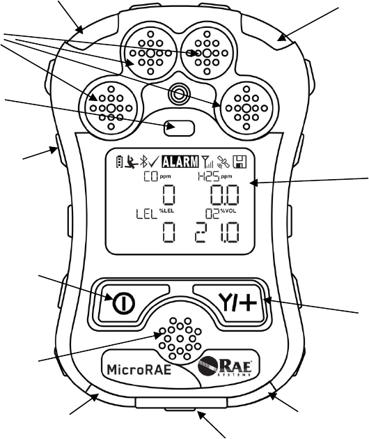
Gas inlets
Display
MODE
Key
Y/+
Key
Alarm
Buzzer
LED
LED
LED
LED
Alligator
Clip
(on back)
Charging and
Communication
Contacts
(on bottom)
Light
Sensor
MicroRAE User’s Guide
12
3. User Interface
The MicroRAE’s user interface consists of the display, LEDs, an alarm buzzer, and two keys.
3.1. Display Overview
The LCD display provides visual feedback that includes the sensor types, readings, battery
condition, and other functions.
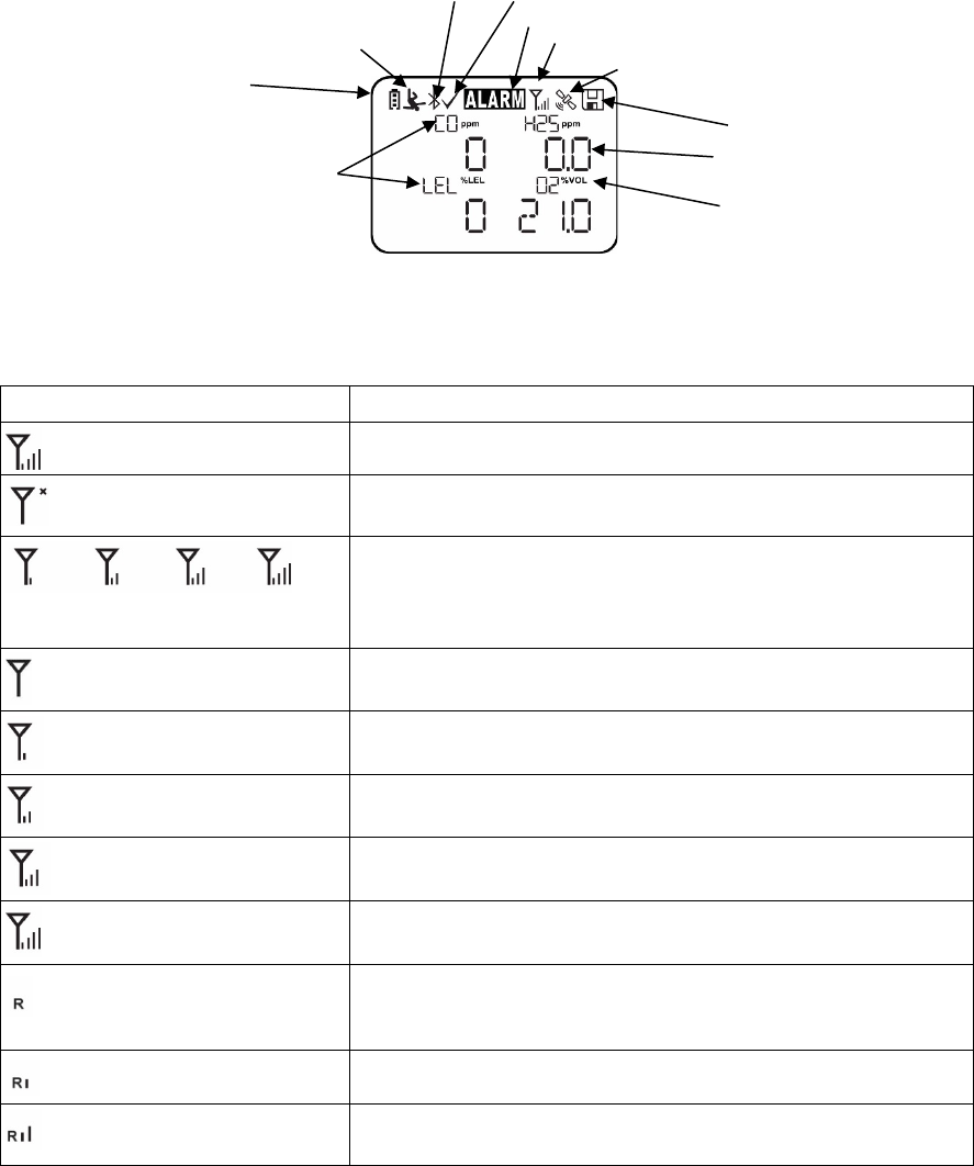
3.1.1. Status Indicator Icons
Along the top of most screens are status indicators that tell you whether a function is operating
and/or its strength or level.
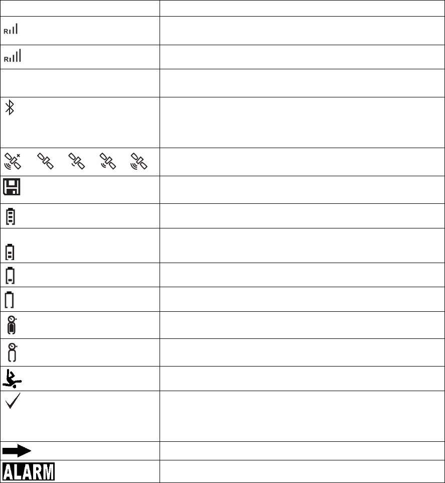
Icon
Function
Mesh and Wi-Fi enabled and power on
Mesh Radio or Wi-Fi Wireless status: the radio is off (replaced
by “R” when Roaming is on).
Mesh Radio or Wi-Fi Wireless status: the radio is on (replaced
by “R” when Roaming is on). Wireless strength is indicated by
0 to 4 bars. Flashing icon without bars indicates network has
not been found.
Cannot find network (blinking icon)
Mesh Radio & Wi-Fi signal less than 20%
Mesh Radio & Wi-Fi signal 21% to 50%
Mesh Radio & Wi-Fi signal 51% to 70%
Mesh Radio & Wi-Fi signal 71% to 100%
Roaming status: “R” blinks when trying to find a network
(replaced by antenna when Roaming is off). “R” is solid when
network communication established.
Network joined, signal very low RSSI (0% to 19%)
Network joined, signal low RSSI (20% to 49%)
Unit of measure
Reading value
Sensor type
Datalog Status indicator
Battery Status
Man Down alarm on
Calibration and bump test
up to date
BLE on
Instrument in alarm
Mesh Radio on and signal strength
GPS on and signal strength
MicroRAE User’s Guide
13
Icon
Function
Network joined, signal medium RSSI (50% to 69%)
Network joined, signal good RSSI (70% to 100%)
No radio icon: The instrument is not equipped with a radio
module.
BLE (Bluetooth Low Energy)
If installed but disconnected, the icon blinks 1 time per second.
If connected with another device, the icon is shown and does
not blink.
GPS Status: off, no satellites found, 1 to 3 satellites, 4 to 8
satellites, 9 to 12 satellites.
Datalogging status (shown when datalogging is on, blank when
off).
Battery voltage is greater than 70%
Battery voltage is 41% to 70%
Battery voltage is 11% to 40%
Battery voltage is less than 10% (icon blinks)
Calibration overdue.
Bump test overdue.
Man Down alarm enabled.
All sensors tested and calibrated tick mark (all sensors have
been bump tested and calibrated; no sensor is overdue for a
bump test or calibration according to the intervals configured
on the instrument.
Go to next page.
Instrument is in alarm (flashes)
MicroRAE User’s Guide
14
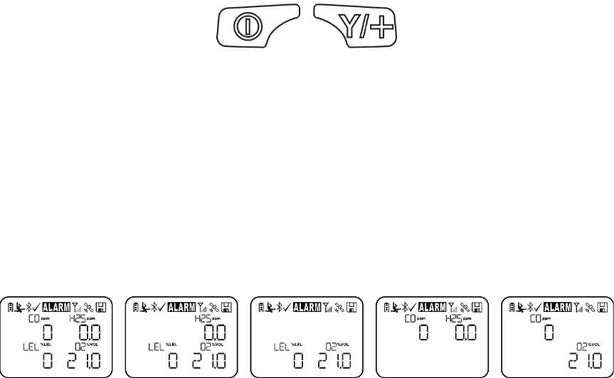
3.1.2. Keys & Interface
The MicroRAE has two keys:
MODE
Y/+
In addition to their labeled functions, the keys labeled [MODE] and [Y/+] act as “soft keys” that
control different parameters and make different selections within the instrument’s menus. From
menu to menu, each key controls a different parameter or makes a different selection.
In addition to the functions described above, either key can be used to manually activate display
backlighting. Press a key when the backlighting is off to turn it on.
3.2. Screen Display For Various Numbers Of Active Sensors
The MicroRAE can accommodate from one to four sensors. When one or more sensors is either
not installed or turned off, the display only shows the installed, active sensors:
MicroRAE User’s Guide
15
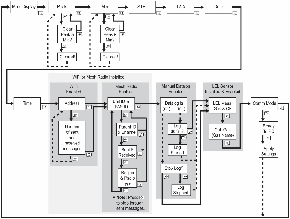
3.3. Menus
The reading menus are easy to step through by pressing the [MODE] and [Y/+] key.
* If the MicroRAE is Wi-Fi equipped: Wi-Fi-equipped instruments can receive up to five
messages. If a message has been received by the MicroRAE, the number of messages is
displayed (1 MSG, etc.). The display shows the message sequentially, cycling through the
message each half-second. The Message number, “page” of the message (it automatically
breaks a message across screens), and received time and date are shown. Up to five messages
can be received by the MicroRAE. Pressing [MODE] steps through the messages. When “Exit” is
shown, press [Y/+] to return to the Main Display.
Note: In most cases, if no buttons are pressed at any of the menu steps for 60 seconds, the
instrument reverts to the main display.
*
MicroRAE User’s Guide
16
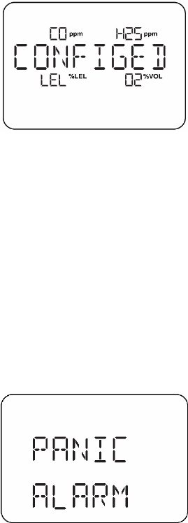
3.4. Glance Mode
If you want to check your instrument’s configuration and it is turned off, you do not have to turn it
on. Press and hold [Y/+] until the screen illuminates and shows the configuration. This tells you
the installed sensors:
Press [Y/+] to advance through screens that tell you if the radio is on, BLE is on, GPS is on, Wi-Fi
is on, etc. These change, depending on the instrument’s configuration.
To exit, press [MODE], and the display shuts off.
Note: If you do not press a button for 60 seconds, it turns off automatically.
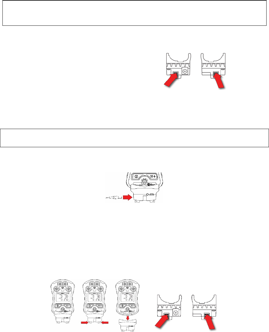
3.5. Panic Alarm
Press and hold [Y/+] at any time to trigger the Panic Alarm. The display shows “PANIC ALARM”
and sends a message to the Location Manager or ProRAE Guardian.
(Note: Use ProRAE Studio II to define information and its prioritization for viewing.)
In addition, the instrument alarms (audible and visible) four times per second. The instrument also
sends an emergency message to the Location Manager or ProRAE Guardian.
Press [Y/+] to clear the alarm. The alarm stops and the display returns to the main reading
screen.
3.6. Confidence LED
You can use ProRAE Studio II to program the MicroRAE to continually provide an LED blink
every 3 seconds so that you can tell without looking closely that the instrument is working.
MicroRAE User’s Guide
17
4. Mesh Wireless Control And Submenus
When you step through the main menu, as shown in the Menus diagram, there are four screens
for wireless communication, containing information on wireless settings and status. If Roaming is
not turned on, then you must set a PAN ID in order to communicate with a Mesh Network.
Note: These are only present if the MicroRAE is equipped with a Mesh Network wireless module.
MicroRAE User’s Guide
18
5. Battery Charging
Always fully charge the battery before using the MicroRAE. Its Li-ion battery is charged by placing
the MicroRAE in its Travel Charger (P/N: M03-3005-000) or Charging Cradle. Contacts on the
bottom of the instrument meet the Travel Charger’s or Charging Cradle’s contact pins,
transferring power.
Note: Before attaching the MicroRAE to a charger, visually inspect the contacts to make sure
they are clean. If they are not, wipe them with a soft, dry cloth. Do not use solvents or cleaners.
WARNING
To reduce the risk of ignition of hazardous atmospheres, recharge, remove or replace the
battery only in an area known to be non-hazardous!
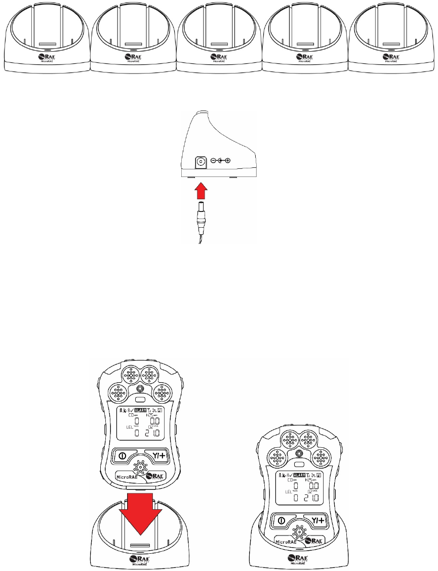
TO AVOID DAMAGE, DO NOT ATTACH OR REMOVE THE TRAVEL CHARGER
WITHOUT SQUEEZING THE LATCHES!
Next, put the plug from the power supply (P/N: 500-0036-102) into the jack on the side of the
Travel Charger.
Plug the other end of the charger into a power source (AC outlet or mobile power port in a
vehicle, depending on the model). When power is applied and the MicroRAE’s battery is
charging, the LED glows red. The LED glows green when the battery is fully charged.
Note: For mobile charging, only use Automotive Charging Adapter (P/N 003-3004-000) from RAE
Systems.
To remove the MicroRAE from the Travel Charger, squeeze the latches on the sides of the Travel
Charger and pull it away from the instrument. Always press near the top of the latches, not the ends.
Align the Travel Charger with the middle of the MicroRAE, squeeze the latches on both
sides of the Travel charger, and press it until it is firmly attached to the MicroRAE.
Then release the latches. Make sure you press the latches close to
the instrument
instead of at their ends.
MicroRAE User’s Guide
19
5.1. Charger Station (Multi-Charger)
A Multi Charger (P/N: M03-0300-000) is available for charging up to five MicroRAE instruments at
one time. Note: It uses a different AC adapter (P/N: 500-0156-000) than the travel charger.
Insert the plug from the power supply into the jack on the side of the Multi Charger:
Plug the other end of the charger into a power source.
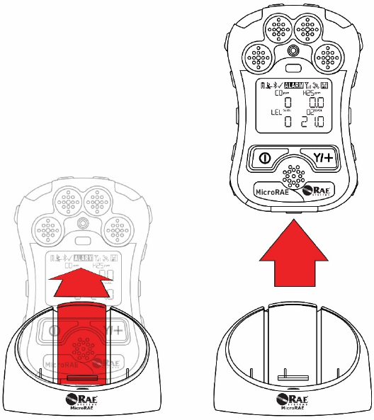
5.1.1 Charging With The Multi Charger
Press the MicroRAE into any of the Multi Charger’s cradles. It should be held firmly in place. If the
power is connected to the Multi Charger, the LED indicator on the cradle should glow. When
power is applied and the MicroRAE’s battery is charging, the LED glows red. The LED glows
green when the battery is fully charged.
MicroRAE User’s Guide
20
Remove the instrument from the cradle by tilting the release on the rear of the charging cradle
away from the instrument and lifting the MicroRAE.
MicroRAE User’s Guide
21
5.2. Battery States
The battery icon on the display shows how much charge is in the battery and alerts you to any
charging problems.
Battery low
1/3 charge
2/3 charge
Full charge
When the battery’s charge falls below a preset voltage, the instrument warns you by beeping
once and flashing once every minute. The instrument automatically powers down within 10
minutes, after which you will to recharge the battery.
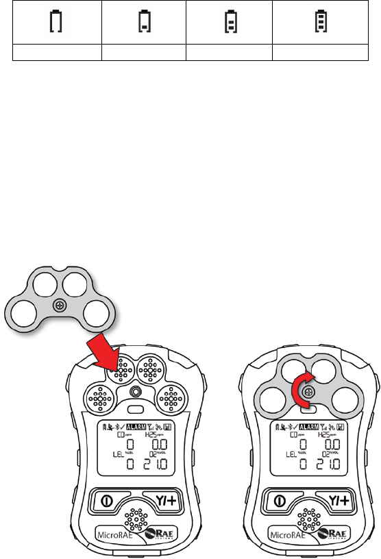
6. External Filter
The External Filter (M03-3009-000) is designed to prevent debris from entering the MicroRAE in
dirty or dusty environments. Align the filter over the sensor openings and tighten the Philips screw
to secure it in place. Replace the filter when it appears dirty.
MicroRAE User’s Guide
22
7. Turning The MicroRAE On And Off
7.1. Turning The MicroRAE On
With the instrument turned off, press and hold the [MODE] key until the audible alarm stops, and
then release.
When starting up, the MicroRAE turns the backlight on and off, beeps once, blinks once, and
vibrates once. A RAE Systems logo should appear first. During a normal startup, this is followed
by a progression of screens that tell you the MicroRAE’s current settings.
Then the MicroRAE’s main reading screen appears. It takes 45 seconds for some sensors to
show a reading, so if any have not warmed up by the time the main screen is shown, you will see
“- -” instead of a numerical value until the sensor provides data (if you turn a sensor off and on
again, it also shows “- -” for up to 45 seconds). Then it displays instantaneous readings similar to
the following screen (depending on the sensors installed) and is ready for use.
Note: If the battery is completely empty, the MicroRAE shuts off. You should charge the before
turning it on again.
IMPORTANT!
If a major error that prevents the MicroRAE from functioning is found during startup, the message
“Contact Service” is shown on the display. The instrument should be shut off and serviced.
7.2. Turning The MicroRAE Off
Press and hold [MODE]. A 5-second countdown to shutoff begins. You must hold your finger on
the key for the entire shutoff process until the MicroRAE is powered off.
Caution: The alarm is very loud. During startup, you can mute most of the sound by holding a
finger over the alarm port. Do not put tape over the alarm port to permanently mute it.
MicroRAE User’s Guide
23
7.3. Testing Alarm Indicators
Under normal-operation mode and non-alarm conditions, the buzzer, vibration alarm, LED, and
backlight can be tested at any time by pressing [Y/+] once.
IMPORTANT!
If any alarm does not respond, check MicroRAE’s alarm settings to make sure all alarms are
enabled (selected setting under Programming/Alarms/Alarm Settings should be “All Enabled”). If
any alarms are enabled but not functional, the instrument should not be used.
7.4. Glance Mode
Glance Mode allows you to get vital information without turning the MicroRAE on. You can check
information such as the instrument’s model number, installed sensor types, etc., which may help
when taking inventory of instruments and their sensors or when working with service or support
personnel. Glance Mode can be enabled/disabled via ProRAE Studio II.
7.4.1 Enter Glance Mode
Note: The instrument must be configured so that Glance Mode is turned on (the default mode is
“On”). This can be done in ProRAE Studio II.
With the MicroRAE turned off, press and hold [Y/+] to enter Glance Mode. The feature is latched,
meaning that it runs even after you release the [Y/+] key. If you see the message “GLANCE
DISABLED,” you must configure the instrument to use Glance Mode.
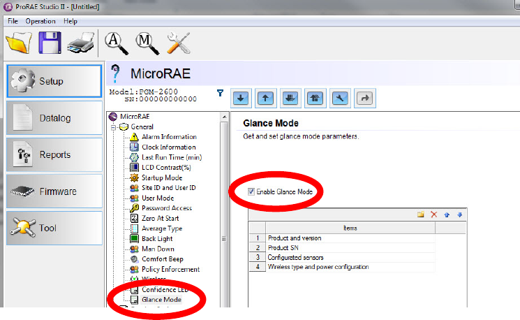
If Glance Mode is enabled, the first screen is displayed. After releasing [Y/+], other screens
release, other screens can be displayed by pressing the [Y/+] Key. In ProRAE Studio II, Glance
Mode can be enabled or disabled by checking or unchecking the box labeled “Enable Glance
Mode.”

MicroRAE User’s Guide
24
7.4.2 Screens
Every screen displayed in sequence as configuration. Press [Y/+] to advance to the next screen.
Press [MODE] to exit Glance Mode and turn the instrument off. The screens are shown in
sequence.
7.4.3 Exit Glance Mode
MicroRAE exits Glance Mode and turns off when you press the [MODE] key. In addition, if you
do not press either key in 60 seconds, the MicroRAE automatically exits Glance Mode.
7.5. Comfort Beep
A Comfort Beep is a single beep of the audible alarm at 60-second intervals that provides a
reminder that the MicroRAE that it is functioning. It can be turned on or off.
7.6. Man Down Alarm
The Man Down Alarm is a critical and potentially lifesaving safety feature of every MicroRAE. The
Man Down Alarm is based on the premise that if the instrument is motionless when it is not
supposed to be, something wrong may be happening to its user. If that is the case, the MicroRAE
not only goes into alarm locally on the instrument, but also remotely, over a wireless network, to
notify people in the vicinity, as well as remote safety officers at a command center, that a person
is down, so that help can be dispatched quickly.
Note: Remote notification requires wireless connection to a network.
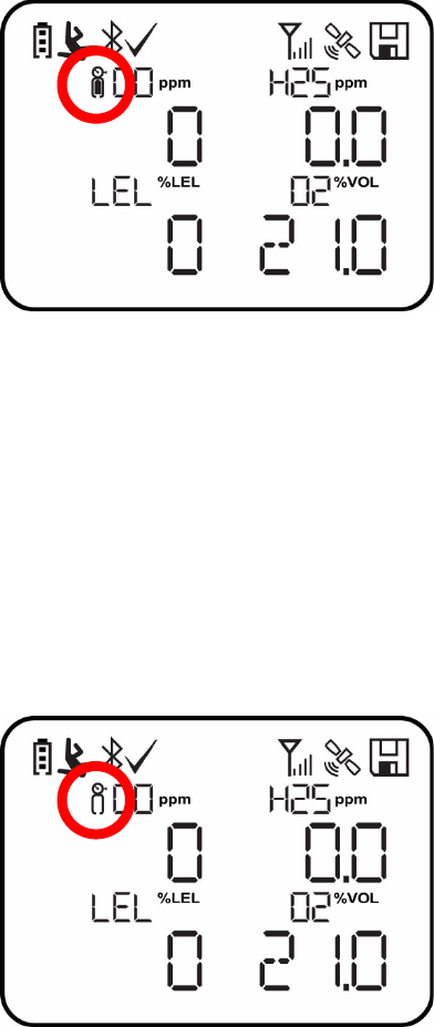
Whenever the Man Down feature is on, the main screen displays a Man Down icon along the top
to indicate it is active:
IMPORTANT!
When gas alarm conditions exist at the same time as the Man Down alarm is activated, the pre-alarm
stage is skipped, and the instrument goes straight into Super Alarm (gas and Man Down) with four
beeps/flashes per second.
When the Man Down feature is on and there is no gas alarm, the MicroRAE senses that it is
motionless for the amount of time set in the “Motionless Time” parameter via ProRAE Studio II. If the
instrument is not moved during that time, then a pre-alarm is activated to alert the user, and shows the “OK?”
screen. Pressing [Y/+] clears the alarm and returns the MicroRAE to its normal operation. Pressing [MODE]
sets it into Man Down Alarm (and if wireless connectivity is enabled, a Man Down message is sent in real time
to remote observers). If neither key is pressed, then after the countdown, it goes into Man Down Alarm (again
sending a message to remote observers if wirelessly enabled).
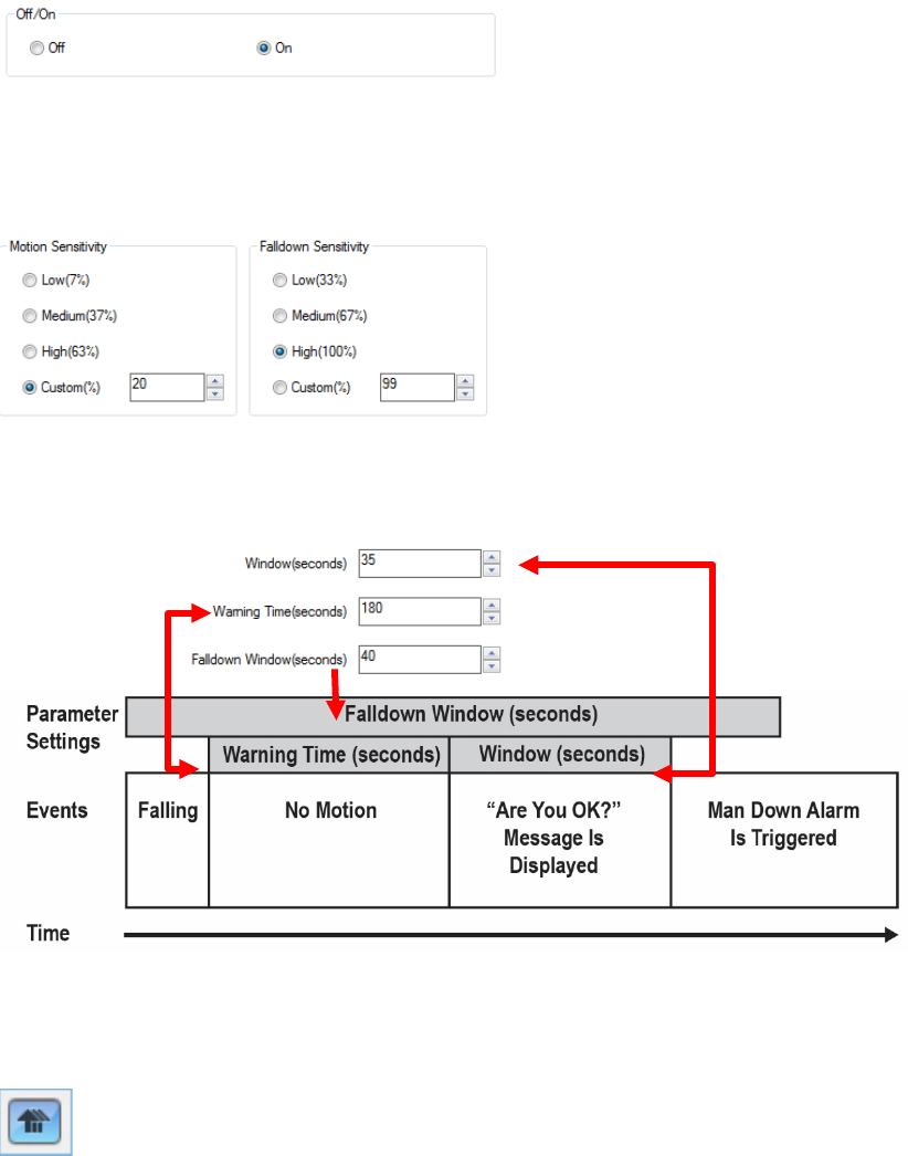
Settings for Man Down are available in ProRAE Studio II for:
• Off/On
• Motion Sensitivity (set to low, medium, high, or custom percentage)
• Falldown Sensitivity (set to low, medium, or high to compensate for ambient vibration or motion)
• Window (time the instrument is motionless before initiating a pre-alarm, in seconds)
• Warning Time (countdown, in seconds, from pre-alarm to Man Down alarm)
• Falldown Window (time after falling down is sensed, in seconds); Whenever the acceleration
speed is greater than the Falldown Sensitivity, the Man Down feature is invoked.

MicroRAE User’s Guide
25
When the Man Down alarm is activated, the buzzer sounds and LEDs flash continuously, and a countdown
begins.
• If the MicroRAE’s user presses [Y/+] for “Yes” in response to the “OK?” question on the screen
before the countdown reaches zero, the Man Down alarm stops and the main reading screen is
displayed.
• If the person does not press [Y/+] for “Yes” in response to the “OK?” question on the screen
before the countdown reaches zero, the Man Down alarm is sounded and LEDs flash
continuously.
• If the person presses [MODE] during the countdown, answering the “OK?” question by pressing
[MODE] for “No,” the Man Down alarm starts.
If wireless connectivity is enabled, and the MicroRAE is connected to a network, a Man Down message is
also sent to remote observers.
IMPORTANT!
When using the Travel Charger or Truck Mount to charge a MicroRAE, the Man Down alarm is
automatically disabled so that the instrument does not go into Man Down alarm because of inactivity. This
requires no changes to the instrument’s settings.
Please note that Travel Chargers with a serial number lower than M0320001U5 and Truck Mounts with
serial numbers lower than M035000170 do not support this feature. It is also recommended that older
MicroRAE instruments have their firmware upgraded to version 1.10 or higher.
7.6.1 Parameter Settings And Sequence Of Events
When a fall is sensed, as determined by the Motion Sensitivity and Falldown Sensitivity settings,
the Falldown Window starts. If motion resumes, then the instrument resets itself and is ready for
the next fall or motionless period.
7.6.1.1. Parameters Configured By ProRAE Studio II
Index
Parameter
Default Value
Range
1
Window time
30 seconds
30 to 90 seconds
2
Warning time
30 seconds
30 to 180 seconds
3
Falldown Window time
180 seconds
0* to approximately 1,000 seconds
4
Motion Sensitivity
Medium
Low (7%)
Medium (37%),
High (63%),
Custom
5
Fall Sensitivity
Medium
Low (33%),
Medium (67%),
High (100%),
Custom
* If the Falldown Window value is set to “0,” the Man Down algorithm focuses only on motionless
behavior. If the Falldown Window value is not set to zero, the algorithm uses acceleration to
trigger its function.
If acceleration is sensed, and motion does not resume, then the Warning Time starts. During this
period, the instrument waits for motion. If no motion occurs by the end of the Warning Time, the
Window period is entered. During that time, the display shows the “Are You OK?” message. The
buzzer sounds and LEDs flash continuously, and a countdown begins.
• If the MicroRAE’s user presses [Y/+] for “Yes” in response to the “Are You OK?” question on
the screen before the countdown reaches zero, the Man Down alarm stops and the main
reading screen is displayed.
MicroRAE User’s Guide
26
• If the person does not press [Y/+] for “Yes” in response to the “Are You OK?” question on the
screen before the countdown reaches zero, the Man Down alarm is sounded and LEDs flash
continuously.
• If the person presses [MODE] for “No” during the countdown, the Man Down alarm starts.
If wireless connectivity is enabled, and the MicroRAE is connected to a network, a Man Down message is
also sent to remote observers.
7.6.1.2. Turn Man Down On Or Off
Turn on the Man Down feature, or turn it off, using ProRAE Studio II.
7.6.1.3. Set The Sensitivity
Individual sensitivity settings for Motion (acceleration) and Falldown allow for customization to
individuals or activities. Default values are set at the factory, but it can be helpful to try other
settings in order to customize an instrument’s response.
7.6.1.4. Set The Times
Once a trigger occurs, there is a time before a warning is displayed and when the Man Down
alarm is initiated.
7.6.1.5. Upload Settings To The MicroRAE
When any changes to Man Down (or any other) settings are made in ProRAE Studio II, you must
upload them to the instrument in order for them to be used. Click the “Upload all settings” button.
MicroRAE User’s Guide
27
7.7. Calibration Status
If any sensor requires calibration, then “Calibration Overdue” icon is shown by the sensor name in
the display:
Calibration is required if:
• The sensor module has been replaced with one whose calibration is overdue.
• The defined period of time between calibrations has been exceeded, according to the
policy set for the instrument.
• If you have changed the calibration gas type without recalibrating the instrument.
• The sensor has failed a previous calibration.
7.8. Bump Status
If any sensor requires a bump test, then “Bump Overdue” icon is shown by the sensor name in
the display:
A bump test is required if the defined period of time between bump tests has been exceeded.
This interval is set by an administrator using ProRAE Studio II.
MicroRAE User’s Guide
28
8. Modes Of Operation
The MicroRAE has two user modes, selectable through ProRAE Studio II.
8.1. Basic User Mode
In Basic User Mode, some restrictions are applied, including password protection that guards
against entering Programming Mode by unauthorized personnel.
8.2. Advanced User Mode
In Advanced User Mode, there are no access restrictions (you do not need a password), and the
MicroRAE provides the indications and data you need most for typical monitoring applications.
9. Programming
The menu in Programming Mode is to adjust many of the MicroRAE’s settings, calibrate sensors,
and initiate communication with a computer. It has the following submenus:
• Calibration
• Sensor On/Off
• Clear Datalog
• Monitor Setup
• Set Radio (Wireless)
Note: Some settings are only visible and can only be changed in ProRAE Studio II. This requires
connecting the instrument to a computer running ProRAE Studio II and having administrative
privileges. For a list of which parameters can be set in Programming Mode on the MicroRAE, in
ProRAE Studio II, or both, refer to “Editing Features” on page 64.
9.1. Enter Programming In Basic Mode
1. To enter Programming Mode, press and hold [MODE] and [Y/+] until you see the Password
screen.
2. Input the 4-digit password:
• Increase the number from 0 through 9 by pressing [Y/+].
• Step from digit to digit using [MODE].
• After inputting the password’s four digits, advance to “?”
• Press [Y/+] to register the password and enter Programming Mode. If you receive the
message “PASS ERR RETRY?” press [Y/+] to re-enter the password. Otherwise, press
[MODE] to return to the main screen.
If you make a mistake, you can cycle through the digits by pressing [MODE] and then using [Y/+]
to change the number in each position.
Note: The default password is 0000.
Note: The password screen only appears when you enter the Programming Mode the first time
after turning the instrument on in Basic Mode. If you have input the correct password, you do not
have to input it again to enter Programming Mode until you turn the instrument off and on again.
MicroRAE User’s Guide
29
Once you enter Programming Mode, the Calibration screen is shown. Press [MODE] to step
through the programming screens.
9.2. Enter Programming In Advanced Mode
To enter Programming Mode, press and hold [MODE] and [Y/+] until you see the Calibration
screen. No password is necessary in Advanced Mode. Note: Some parameters can only be
viewed or changed in ProRAE Studio II.
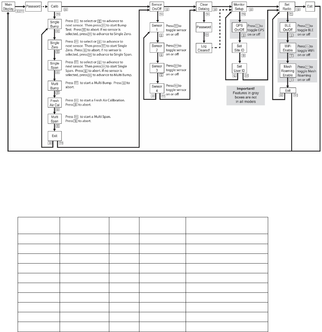
9.3. Menus And Submenus
In Programming Mode, menus and submenus are organized as shown here:
Calibration
Sensor On/Off
Clear
Datalog
Monitor Setup
Set Radio
Single Bump
Sensor 1 On/Off
GPS On/Off*
BLE On/Off
Single Zero
Sensor 2 On/Off
Set Site ID
Wi-Fi On/Off**
Single Span
Sensor 3 On/Off
Set User ID
Sent History**
Multi Bump
Sensor 4 On/Off
Mesh Roaming Enable***
Fresh Air Cal
Radio On/Off***
Multi Span
Set PAN ID****
Exit
Set Channel****
Join Network****
Factory Reset****
Exit
* GPS-equipped version only.
** Wi-Fi-equipped version only.
*** Mesh Wirelessly equipped version only.
**** Only available if Roaming is turned off.
MicroRAE User’s Guide
30
9.3.1. Calibration
Use this menu to perform zero or span calibration for one or more sensors, and change the gas
concentration value assumed to be used in span calibration, as well as zero calibration and
calibration reference gas. Refer to “Calibration And Testing” on page 41 for guidance on setting
up the instrument for calibration.
9.3.1.1. Single Bump
You can perform a separate bump test on each individual sensor.
The active sensors’ names are shown in a list. Press [MODE] to highlight the sensor you want to
bump test, and then press [Y/+] to select it.
When the Apply Gas screen is shown, connect the calibration gas to the instrument, and start the
bump test by pressing [Y/+]. If you do not want to perform a single bump test, press [MODE] to
quit.
Note: You can abort a bump test by pressing [MODE] once testing has started.
When the Multi Bump test is done, a screen is shown, with the sensor names and either “Pass” or
“Fail” shown next to them.
9.3.1.2. Single Zero
This allows you to perform zero (fresh air) calibration on individual sensors. For most
applications, the instrument should be zero calibrated in clean ambient air with 20.9% oxygen
(02). For more precise low 02 percentage accuracy, and after a new 02 sensor is put into the
instrument, zeroing should be performed with nitrogen (N2). A zero calibration should precede a
span calibration.
The active sensors’ names are shown in a list. Press [MODE] to highlight the sensor you want to
zero calibrate, and then press [Y/+] to select it.
When the Zero Calibration screen is shown with the sensor name and its measurement unit, start
the zero calibration by pressing [Y/+]. If you do not want to perform a calibration, press [MODE] to
quit.
Note: You can abort a zero calibration by pressing [MODE] once testing has started.
When the zero calibration is done, the Calibration Results screen is shown with either “Pass” or
“Fail” shown.
9.3.1.3. Single Span
Instead of performing a span calibration on more than one sensor simultaneously, you can select a
single sensor and perform a span calibration.
The active sensors’ names are shown in a list. Press [MODE] to highlight the sensor you want to
span calibrate, and then press [Y/+] to select it.
When the Apply Gas screen is shown with the sensor name and its measurement unit, connect a
cylinder of span gas, start its flow, and then start the span calibration by pressing [Y/+]. If you do
not want to perform a span calibration, press [MODE] to quit.
Note: You can abort a span calibration by pressing [MODE] once testing has started.
When the span calibration is done, the Calibration Results screen is shown with either “Pass” or
“Fail” shown.
MicroRAE User’s Guide
31
9.3.1.4. Multi Bump
Depending on the configuration of your MicroRAE and the span gas you have, you can perform a
bump test simultaneously on multiple sensors.
The selected sensors and their values are shown on the screen. With calibration gas connected
to the instrument, start a multiple bump test by pressing [Y/+]. If you do not want to perform a
multiple bump test, press [MODE].
Note: You can abort a multiple bump test by pressing [MODE] once testing has started.
When the Multi Bump test is done, a screen is shown, with the sensor names and either “Pass” or
“Fail” shown next to them.
9.3.1.5. Fresh Air Calibration
You can perform a fresh air calibration simultaneously on multiple sensors. This procedure
determines the zero point of the sensor calibration curve for all the sensors that require a zero
calibration. The instrument should be zero calibrated in clean ambient air with 20.9% oxygen. A
fresh air calibration should precede a span calibration.
The selected sensors are shown on the screen. Start a multiple zero test by pressing [Y/+]. If you
do not want to perform a test, press [MODE].
Note: You can abort a multiple zero test by pressing [MODE] once testing has started.
When the Multi Zero test is done, a screen labeled Calibration Results is shown, with the sensor
names and either “Pass” or “Fail” shown next to them.
9.3.1.6. Multi Span
Depending on the configuration of your MicroRAE and the span gas you have, you can perform a
span calibration simultaneously on multiple sensors.
The selected sensors and their values are shown on the screen. With calibration gas connected
to the instrument and turned on, start a multiple span calibration by pressing [Y/+]. If you do not
want to perform a multiple span calibration, press [MODE].
Note: You can abort a multiple span calibration by pressing [MODE] once testing has started.
When the Multi Span calibration is done, a screen labeled Calibration Results is shown, with the
sensor names and either “Pass” or “Fail” shown next to them.
9.3.1.7. Exit
Exit to “Sensor On/Off”: Press [Y/+].
Return to the top item in the Calibration menu, “Single Bump”. Press [MODE].
MicroRAE User’s Guide
32
9.3.2. Sensor On/Off
You can turn sensors on or off via this set of submenus. The word “ON” or “OFF” below each
sensor’s name tells you its status.
1. Press [MODE] to advance through the sensors.
2. Press [Y/+] to turn a selected sensor on or off.
3. Press [MODE] until “?” is selected.
4. Press [Y/+] to save your selection and exit to “Clear Datalog”. Otherwise, to return to the
first sensor, press [MODE].
9.3.3. Clear Datalog
The instrument displays a floppy disk icon to indicate that a datalog is being recorded. The
instrument stores the measured gas concentration for each sensor, date and time for each
measurement, Site ID, User ID, and other parameters. All data are retained (even after the unit is
turned off) in non-volatile memory so that they can be downloaded at a later time to a PC.
Clearing the datalog erases all data stored in the datalog.
IMPORTANT!
Once the datalog is cleared, the data cannot be recovered.
Note: The datalog is password protected. You must enter the correct password in order to clear
the datalog.
1. Enter the password (the default value is 0000).
2. Press [Y/+].
The message “Log Cleared!” appears briefly on the screen before advancing to “Monitor Setup.”
9.3.4. Monitor Setup
The Monitor Setup menu provides access to settings for GPS, Site ID, and User ID.
9.3.4.1. GPS On/Off
If your MicroRAE is equipped with GPS, you can turn it on or off:
1. Press [Y/+] to enter “GPS On/Off”.
2. Press [Y/+] to turn GPS on or off.
3. Press [MODE] to save your choice and advance to “Set Site ID”.
9.3.4.2. Set User ID
If your MicroRAE is to be used by a specific user, it can have a uniquely named User ID (a name
or numbers or combination) to help identify it in ProRAE Guardian monitoring software. The User
ID must be eight alphanumeric characters.
1. Press [MODE] to advance through the characters from left to right.
2. Press [Y/+] to advance through the letters and numbers (1, 2, 3, A, B, C, etc.).
3. Press [MODE] to register your choice and advance to the next character.
4. When you are satisfied with the Site ID, press [MODE] until “?” is selected.
5. Press [Y/+]. The Site ID is saved, and you see the confirmation message “User ID
Saved.” It automatically advances to “Exit.”
6. Press [Y/+] to exit to “Set Radio.” To return to the Set Site ID, press [MODE].
9.3.4.3. Set Site ID
If your MicroRAE is to be used at a specific site, it can have a uniquely named Site ID (a name or
numbers or combination) to help identify it in ProRAE Guardian monitoring software. The Site ID
MicroRAE User’s Guide
33
must be eight characters in length, with the first four characters alphanumeric (letters and
numerals) and the last four must be numerals.
1. Press [MODE] to advance through the characters from left to right.
2. Press [Y/+] to advance through the letters and numbers.
3. Press [MODE] to register your choice and advance to the next character.
4. When you are satisfied with the Site ID, press [MODE] until “?” is selected.
5. Press [Y/+]. The Site ID is saved, and you see the confirmation message “Site ID Saved.”
It automatically advances to “Set User ID.”
9.3.4.4. Set Radio
Depending on which (if any) radio type is installed in the MicroRAE, there are various settings
that can be changed.
Note: BLE (Bluetooth Low Energy) is included in all MicroRAEs.
9.3.4.5. BLE On/Off
You can turn BLE in all configurations of MicroRAE, or turn Wi-Fi or Mesh Roaming (depending
on how your instrument is configured) on or off via this set of submenus.
1. From “Set Radio,” press [Y/+] to advance to BLE On/Off.
2. Press [Y/+] to turn BLE on or off, or press [MODE] to advance to the next “Set Radio”
screen without changing the BLE on/off status.
9.3.4.6. Wi-Fi On/Off
If your MicroRAE is equipped with Wi-Fi wireless, you can turn it on or off:
Press [Y/+] to toggle Wi-Fi on or off, or press [MODE] to advance to any other radio
type’s on/off screen without changing the Wi-Fi on/off status.
9.3.4.7. Sent History
If your MicroRAE is equipped with Wi-Fi wireless, you can view messages that have been sent
from the MicroRAE (messages must be created in ProRAE Studio II and loaded into the
MicroRAE):
Press [Y/+] to view sent messages. If none have been sent, then “No Msg” is shown.
9.3.4.8. Roaming On/Off
The Roaming function provides continuous wireless connectivity between zones, enabling users
of wireless monitors to travel from one zone/work area to another without losing communication
between their monitor and ProRAE Guardian. You can turn Roaming on and off in ProRAE Studio II.
1. Press [MODE] to toggle Roaming “On” or “Off.”
2. Press [MODE] to scroll to “Exit.”
3. Press [Y/+] to exit.
9.3.4.9. Radio On/Off
This is only available if your MicroRAE is configured with Wi-Fi or Mesh Radio.
Press [Y/+] to turn the radio on or off, or press [MODE] to advance to the next screen without
changing the radio’s on/off status.
MicroRAE User’s Guide
34
9.3.4.10. Set PAN ID
This is only available if your MicroRAE is configured with Mesh Radio.
1. Press [MODE] to advance through the numbers from left to right.
2. Press [Y/+] to advance through the numbers (1, 2, 3, etc.).
3. Press [MODE] to register your choice and advance to the next number.
4. When you are satisfied with the PAN ID, press [MODE] until “?” is selected.
5. Press [Y/+]. The PAN ID is saved, and you see the confirmation message “Apply
Settings”. It automatically advances to “Apply Success”. After 1 second, it automatically
advances to “Set Channel.”
9.3.4.11. Set Channel
This is only available if your MicroRAE is configured with Mesh Radio.
The MicroRAE and any other devices that you want to connect wirelessly must be operating on
the same channel.
Note: For radio modems operating at 868MHz, only channel 0 is available. For other frequencies,
channels 1 through 10 are allowed.
1. Press [MODE] to advance through the numbers from left to right.
2. Press [Y/+] to advance through the numbers (1, 2, 3, etc.).
3. Press [MODE] to register your choice and advance to the next number.
4. When you are satisfied with the channel number, press [MODE] until “?” is selected.
5. Press [Y/+]. The Site ID is saved, and you see the confirmation message “Apply Settings”
followed by “Apply Success”. It automatically advances to “Join Network”.
9.3.4.12. Join Network
This is only available if your MicroRAE is configured with Wi-Fi or Mesh Radio.
You can tell the MicroRAE to automatically join a network. The PAN ID and Channel are shown
for reference (if either is incorrect, you can change it, as described above). Press [Y/+] to join or
[MODE] to advance to “Interval” without making a change. Note: If Roaming is turned on, instead
of a PAN ID number, you see “- - -”.
Press [Y/+] to join a network.
The PAN ID and channel are shown. To join, press [Y/+]. To exit to the “Factory Reset,” press
[MODE].
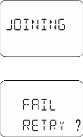
While it is searching for a network to join, the display shows this message:
If it is unsuccessful, the display shows this message:
Check your other settings, as well as those of the network you are trying to join.
You can press [Y/+] to retry or [MODE] to exit without joining a network.
MicroRAE User’s Guide
35
9.3.4.13. Factory Reset
Restore all the wireless settings to their original factory defaults.
Caution! Once you reset the wireless settings, you cannot retrieve any of the settings deleted by
performing this reset.
Press [Y/+] to initiate a factory reset. You see this screen:
Reset Radio?
• Press [Y/+] to reset the wireless settings. You see the message “Pls Wait” while it resets
to factory settings. When it is done it shows the PAN ID and Channel.
• Press [MODE] to exit.
9.3.4.14. Exit
Exit to the main reading screen: Press [Y/+].
Return to the top of the “Set Radio” menu: Press [MODE].

MicroRAE User’s Guide
36
9.4. Parameters Accessed Through ProRAE Studio II
Some parameters can be accessed through the menus in the MicroRAE, but some can only be
viewed and set in ProRAE Studio II.
9.4.1. Alarm Mode
You can program the MicroRAE so that there are two ways to shut off an alarm:
Auto Reset
When the alarm condition is no longer present, the alarm stops and resets itself.
Latch
The latched setting only controls alarms for High Alarm, Low Alarm, STEL
Alarm, and TWA alarm. When an alarm is in “latched” mode, the alarm signal
remains on even when the alarm condition is no longer present Press [Y/+] to
acknowledge and reset alarm signals.
9.4.1.1. Alarm Settings
You can enable/disable any combination of light (LEDs), buzzer, and vibration alarms.
Settings:
• All Enabled
• Lights Only
• Vibration Only
• Buzzer Only
• Buzzer & Light
• Buzzer & Vibration
• Vibration & Light
• All Disabled
9.4.1.2. Clock Information
Set the date and time manually or check the checkbox to synchronize with your PC.
Date
Month (MM) and Day (DD) have two digits each, while the year (YYYY) uses four digits.
Time
The time must be set using the 24-hour format, following hours, minutes, and seconds
(HH:MM:SS).
9.4.1.3. Last Run Time (min)
This read-only parameter tells how long the MicroRAE ran during its last session.
9.4.1.4. LCD Contrast (%)
The display’s contrast can be increased or decreased from its default setting. You may not need
to ever change the default setting, but sometimes you can optimize the display to suit extreme
temperature and ambient brightness/darkness conditions. Its midpoint is 50%.
MicroRAE User’s Guide
37
9.4.1.5. Startup Mode
You can choose Normal or Fast startup. Normal startup shows more information during the
startup process, but Fast shows fewer and therefore gets from power-on to reading more quickly.
9.4.1.6. Password Access
View or change the password. The default value is “0000.” It must have four digits.
9.4.1.7. Zero At Start
If your MicroRAE has been configured to perform a zero (fresh air) calibration upon startup, called
Zero At Start, then the startup routine is interrupted so that you can perform a fresh air calibration.
Choices are On or Off.
9.4.1.8. Average Type
Get or set the instrument’s averaging type. These include Moving Average, TWA Average, and
No Average Operation.
9.4.1.9. Back Light
The display’s backlight can be set to illuminate either automatically, based on ambient light
conditions, or manually, or it can be shut off. In addition, you can view or change the Back Light
Trigger Value.
9.4.1.10. Messaging
Get or set pre-configured messages (maximum length is 20 characters, including spaces or
symbols).
9.4.1.11. Datalog Options
Data Selection. Get or set the MicroRAE’s data type. Options include Minimum, Average,
Maximum, and Real Time.
Log Mode. Get or set the instrument’s log mode. Options include Datalog Start Type and
Memory Full Action
Log Interval. Get or set the log interval (in seconds).
Note: When the instrument is in alarm, the datalog interval automatically switches to 1 second
until the alarm is cleared. This includes the following types of alarms:
• Man Down alarm
• Panic alarm
• Gas alarm (including latched) for Low, High, STEL, TWA, LowLow, and Over Range
9.4.1.12. Gas Information
Gas Library Information. The current gas library’s information is shown, including its version,
date, time, and total number of gases included in it. These are tailored to the sensors for best
accuracy.
Custom Gas List. Get and set custom gases in the instrument’s library. You can provide a name,
formula, gas number, and parameters such as molecular weight, Correction Factor (CF), alarms
and Span value.

MicroRAE User’s Guide
38
9.4.1.13. Sensor Information
Sensor Summary. View installed and enabled sensors, and set whether a sensor is enabled or
disabled.
Sensor data is included for each sensor below Sensor Summary. Everything you need to know
about a sensor is shown, plus you can set Bump Test and Calibration Intervals, Span and
applicable Alarms, plus Calibration Gas and Measurement Gas.
Sensor Alarm. Get or set the sensor alarm parameters. For each sensor, you can set High
Alarm, Low Alarm STEL Alarm (if applicable), and TWA Alarm (if applicable).
Sensor Span. Get or set the sensor span gas concentrations.
Sensor Bump Test. Get or set the sensor bump test parameters. This includes setting the
interval (number of days) for bump testing.
Multi-Calibration. You can select which sensors you want included when you perform a Multi
Calibration. Use the check boxes to make your selections.
Sensors to Log. You can select which sensors you want included in your datalogs. Use the
check boxes to make your selections.
Sensor Maintenance. After a new sensor is installed, list its name and serial number.
10. Policy Enforcement
The MicroRAE can be configured via ProRAE Studio II to enforce a facility/company’s
requirements that calibration and/or bump testing be performed at specified intervals, and to warn
the user that calibration/bump testing is required. In addition, it can require calibration or bump
testing and not allow normal operation of the instrument unless calibration or bump testing is
performed.
If Policy Enforcement is enabled and if the instrument has been bump tested and calibrated in
compliance with the policy settings, a check-mark icon is included along the top of the MicroRAE
screen:
If Policy Enforcement is enabled, then after startup the MicroRAE displays a screen that informs
the user that the instrument requires either a bump test or a calibration. If both are required, then
they are shown in sequence.
MicroRAE User’s Guide
39
10.1. Setting Policy Enforcement
You must use ProRAE Studio II to make changes to Policy Enforcement settings.
Make sure the AC adapter is connected and that a USB cable is connected between the Travel
Charger and a computer running ProRAE Studio II.
1. Turn on the MicroRAE. Allow the system to start up and go through its startup routine.
2. Press [MODE] until “Comm Mode?” is displayed.
3. Press [Y/+]. The screen now displays: “Ready To PC”.
4. Start ProRAE Studio II.
5. Select “Administrator.”
6. Input the password (the default is “rae”).
7. Click “OK.”
8. Click “A” (detects instruments automatically).
9. Click on the instrument’s icon when it appears to highlight it.
10. Click “Select.”
11. Click “Setup.”
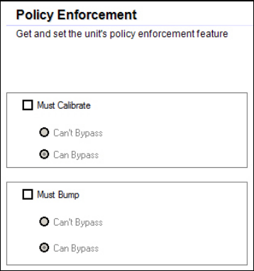
12. Click “Policy Enforcement.”
The Policy Enforcement pane is shown:
You can select “Must Calibrate” and/or “Must Bump” and then set whether the user must
perform the selected operation in order to use the instrument.
MicroRAE User’s Guide
40
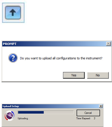
13. Once you have made your selections in ProRAE Studio II, you must upload the changes to
the instrument. Click the icon labeled “Upload current settings to the instrument.”
14. A confirmation screen is shown. Click “Yes” to perform the upload, or “No” to abort.
Uploading takes a few seconds, and this progress bar is shown. You can abort the upload by
clicking “Cancel.”
15. Exit ProRAE Studio II.
16. Press [MODE] on the MicroRAE to apply settings and exit Communication Mode.
MicroRAE User’s Guide
41
11. Setting Wi-Fi Parameters
The MicroRAE’s Wi-Fi parameters for communication cannot be set directly in the instrument.
They must be set in ProRAE Studio II.
11.1. Setting Wi-Fi Parameters In ProRAE Studio II
Note: Before setting parameters, make sure the AC adapter is connected and that a USB cable is
connected between the Travel Charger and a computer running ProRAE Studio II. (Alternatively,
you can use an AutoRAE II Cradle connected to a PC running ProRAE Studio II.)
1. Turn on the MicroRAE. Allow the system to start up and go through its startup routine.
2. Press [MODE] until “Comm Mode?” is displayed.
3. Press [Y/+]. The screen now displays: “Ready To PC”.
4. Start ProRAE Studio II.
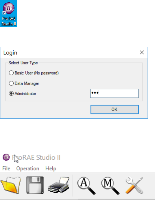
5. Once it has started, select “Administrator.”
6. Log in using your Administrator’s password (the default is “rae”).
7. Click “OK.”
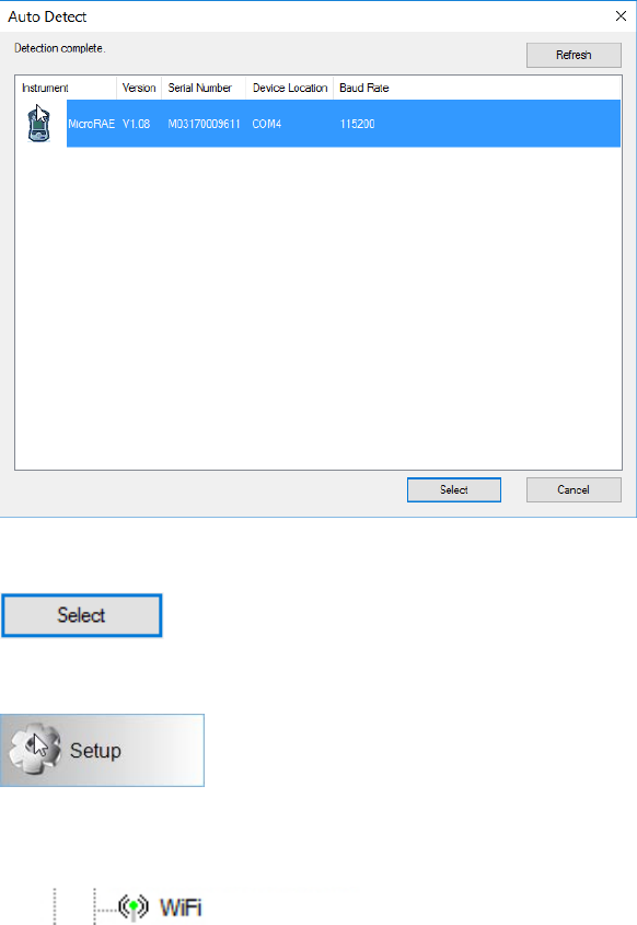
8. Click “A” (for “Automatic” to detect instruments automatically).
MicroRAE User’s Guide
42
9. Click the instrument’s icon when it appears, to highlight it.
10. Click “Select.”
11. Click “Setup.”
12. Wait for parameters to download.
13. Find and click “Wi-Fi” in the list.
MicroRAE User’s Guide
43
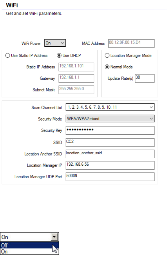
Wi-Fi parameters appear in the right pane:
You can now change settings for the MicroRAE.
11.1.1. Wi-Fi Power
Select either “On” or “Off” to set the default power setting for your Wi-Fi-equipped instrument.
Note: Wi-Fi Power can also be turned on or off in the AreaRAE Plus/Pro in the Wireless menu’s
“Wi-Fi.”
11.1.2. MAC Address
This tells you the MAC Address of the radio module in the MicroRAE. Every instrument has a
unique MAC Address.
Note: The MAC Address cannot be changed.
11.1.3. Address
Select “Use Static IP Address” if you have a static IP or “Use DHCP” if your system allows
dynamic hosting configuration. Check with your system administrator to determine which is
appropriate for your network.
If you use a static IP address, you must provide the Static IP address, Gateway, and Subnet
Mask. If you are using DHCP, you do not have to provide these, because they will be filled in
automatically.
MicroRAE User’s Guide
44
11.1.4. Mode
Select “Normal Mode” for MicroRAE, and leave the Update Rate at “30.”
11.1.5. Scan Channel List
Use the default value, or if your system operates on a specific channel, use the pull-down menu
and click individual channels on or off.
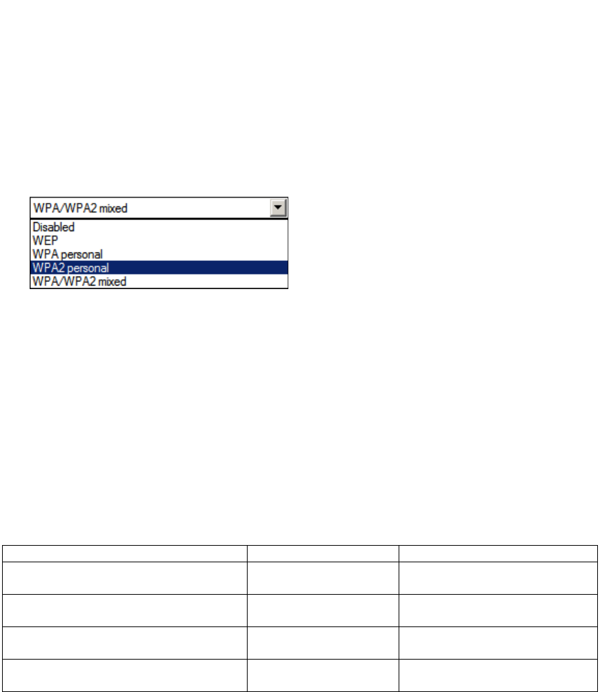
11.1.6. Security Mode
Different types of wireless security guard your network against possible instances of unauthorized
access. Using security, you can:
• Ensure that no one can easily connect to your wireless network without permission
• Personalize access regarding who can configure your wireless settings
• Protect all data that is transmitted through the wireless network
Check with your system administrator for the wireless security mode you should use.
Use the drop-down menu to select the type of security:
Then set your Security Key.
Warning! Using a network with security disabled is not recommended.
11.1.7. Security Key
Depending on the type of security you choose, your key will have to be a different number of
characters.
IMPORTANT!
Configure strong authentication and encryption in your network. WPA2 Personal (also known as
WPA2-PSK) with AES encryption is highly recommended.
Here are characteristics of the different types, their relative security strength, and the number of
characters needed in the key:
Security Type
Security Rank
Number of Characters
WEP (Wired Equivalent Protocol)
Basic
40/64-bit (10 characters)
128-bit (26 characters)
WPA Personal
Wi-Fi Protected Access Personal
Strong
8 to 63 characters
WPA2 Personal
Wi-Fi Protected Access 2 Personal
Strongest
8 to 63 characters
WPA2/WPA Mixed Mode
WPA2: Strongest
WPA: Strong
8 to 63 characters

MicroRAE User’s Guide
45
Strong Password Tips
• Use a unique password. Do not reuse passwords used in other systems or for other
purposes. Avoid using examples found on the Internet, in literature etc.
• Use a long sequence of random characters (at least eight characters).
• Use a mix of different types of characters, such as uppercase and lowercase letters,
numbers, punctuation marks, etc.
• To make the password easier to remember, begin with a sentence, verse, book title, line from
a song etc. Omit or change certain letters. For example, use only the first few letters from
each word, replace some letters with numbers or punctuation marks (for example replace all
letters “a” with dots “.”), etc.
• Avoid using easily guessable phrases, like names, words found in dictionaries, years,
birthdays, phone numbers, etc.
• Avoid using the most popular passwords, such as “123456”, “qwerty”, “password” etc.
Also avoid using them even in modified formats, such as “QWErty” or “Pa55vv0rD”.
• Protect the password while archived. Use trusted and properly configured password vaults for
this purpose.
11.1.8. SSID
The SSID (Service Set Identifier) is a case-sensitive unique identifier attached to the header of
packets sent over a wireless local-area network. Each wireless network in your range will have its
own SSID. Consult with your IT department for the SSID.
11.1.9. Server IP
This is the destination IP address for the instrument to communicate with a computer running
ProRAE Guardian.
11.1.10. Server Port
The port number is distinct from any physical port on a computer such as a COM port or an I/O
port address. It is a 16-bit address that exists only for the purpose of passing certain types of
information to the correct location above the transport layer of the protocol stack.
11.1.11. Upload Wi-Fi Settings To The MicroRAE
When you are done, click this icon to send the new settings to the instrument:
11.1.12. Exit MicroRAE’s Communications Mode
When you want to exit Communications Mode, press [MODE] on the MicroRAE. The screen
shows this message:
Apply Settings?
To apply the new settings, press [Y/+]. Otherwise, press [MODE] and exit.
11.1.13. Disconnect The MicroRAE From The PC
Disconnect the MicroRAE from the PC or remove it from the AutoRAE 2 Cradle.
11.1.14. Test The MicroRAE’s Wi-Fi Operation
Test the MicroRAE in your network to ensure that it communicates properly. Always do this after
performing any changes to wireless parameters.
MicroRAE User’s Guide
46
12. Calibration And Testing
12.1. Bump Testing And Calibration
Prior to each day’s use, every gas detection monitor should be bump tested to confirm the
response of all sensors and activation of all alarms by exposing the monitor to a concentration of
target gas that exceeds the low alarm set point. A bump test is also recommended if the monitor
has been subjected to physical impact, liquid immersion, an Over Limit alarm event, or custody
changes, or anytime the monitor’s performance is in doubt.
To ensure greatest accuracy and safety, only bump test and calibrate in a fresh air environment.
The monitor should be calibrated every time it does not pass a bump test, but no less frequently
than every six months, depending on use and exposure to gas and contamination, and its
operational mode.
• Calibration intervals and bump test procedures may vary due to national legislation.
• Honeywell recommends using calibration gas cylinders containing the gas that is
appropriate to the sensor you are using, and in the correct concentration.
A bump test can be performed either manually or using the AutoRAE 2 Automatic Test and
Calibration System. When a bump test is done manually, the instrument makes a pass/fail
decision based on sensor performance, but the user still has the responsibility to make sure all
the alarms are enabled and functional.
Note: Bump testing and calibration can be performed using an AutoRAE 2 Automatic Test &
Calibration System. An AutoRAE 2 bump test takes care of both the sensor and alarm tests.
Consult the AutoRAE 2 User’s guide for details.
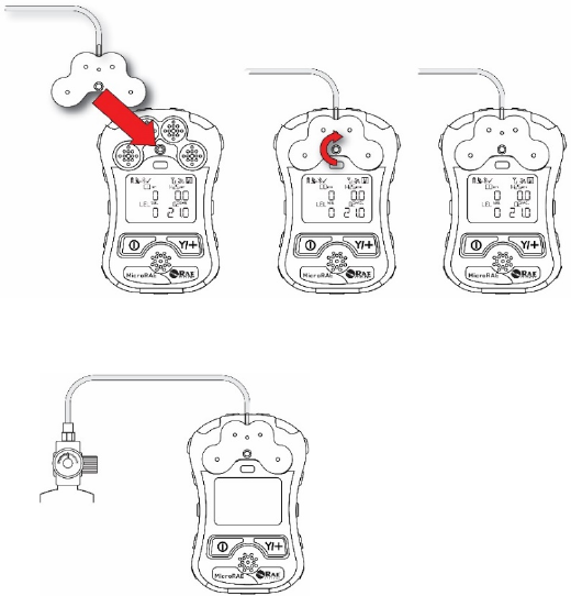
MicroRAE User’s Guide
47
12.1.1. Bump (Functional) Testing (Single Bump or Multi Bump)
The same gas is used for a bump test as for calibration. A constant-flow regulator producing 0.5
liters per minute (1 liter per minute for HCN sensors) should be used, and the calibration adapter
must be installed. The instrument must be connected to a cylinder of calibration gas with supplied
tubing.
1. Turn on your MicroRAE by pressing and holding the [MODE] key, and allow the
instrument to boot up fully until the main measurement screen with sensor names and
readings is shown.
Important! Make sure all of the instrument’s sensors have warmed up before performing a
bump test. The instrument will take the time to warm up the sensors prior to enabling access
to bump test menus. You can tell a sensor has warmed up if you see a reading next to it
name on the display. If it has not warmed up, you see three dashes (“--”) next to it.
2. Install the calibration adapter on the MicroRAE by setting it on over the sensors and
turning the knob until it is snug against the surface of the instrument.
3. Turn on the gas to initiate flow.
4. Connect the calibration adapter to the calibration gas.
5. Press Start ([Y/+] key) to start the bump test, or press [MODE] to quit. While the bump
test is being performed, the readings for each sensor are shown. Once the bump test
completes, pass/fail test results and readings are shown for each sensor.
Important! If one or more sensors fails a bump test, be sure to calibrate those sensors.
6. The bump test is now complete. Press [MODE] to exit to the next bump or calibration
type in the Calibration menu. (Press [MODE] several times until you see “Exit,” and then
press [Y/+] to continue through other menu options.
If all the alarms and all sensors have passed and no sensor is due for a calibration, the
instrument is now ready for use.
MicroRAE User’s Guide
48
12.2. Zero Calibration
This operation sets the zero point of the sensor calibration curve for clean air. It should be
performed before other calibrations.
Note: If you use a zero air cylinder, you must use the MicroRAE Calibration Adapter. Using a
calibration adapter is not necessary for calibration in fresh air.
12.2.1. Zero Calibration
This procedure determines zero points of most sensors. The MicroRAE should be zero-calibrated
in clean air with 20.9% oxygen or with a cylinder of clean zero air.
At the Calibration menu, select “Fresh Air” by pressing [Y/+] once to enter fresh air calibration.
After a timer countdown, the zero calibration is done. The LCD displays the sensor names and
tells you whether each calibration passed or failed, followed by the sensor readings.
Note: You can abort the calibration at any time during the countdown by pressing [MODE].
12.2.2. Single-Sensor Zero Calibration
Select the sensor and then start the calibration by pressing [Y/+]. You can abort the procedure
anytime by pressing [MODE].
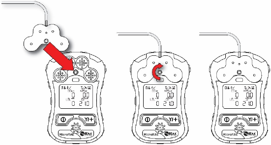
MicroRAE User’s Guide
49
12.3. Span Calibration
This procedure determines the second point of the sensor calibration curve for the sensor.
Note: When a manual calibration is performed, the readings shown are in the equivalent units of
the calibration gas, and not the measurement gas. When performing a Span calibration, the
Calibration Adapter must be used for supplying calibration gas to all sensors at one time:
1. Align the Calibration Adapter’s main body with the indented area around the MicroRAE’s
gas inlets.
2. Turn the knob clockwise to secure the Calibration Adapter to the instrument.
3. Connect the hose to the Calibration Adapter and to its gas source.
4. Make sure the Calibration Adapter is securely attached before starting the flow of
calibration gas. (The Calibration Adapter has small grooves on its underside to allow gas to
escape after passing over the sensors.)
12.3.1. Multi-Sensor Span Calibration
This lets you perform a span calibration on multiple sensors simultaneously. It requires using the
appropriate span gas and that the concentration labeled on the gas cylinder matches the
concentration programmed in the MicroRAE.
1. Start the flow of calibration gas.
2. Attach the calibration adapter and gas to the MicroRAE.
3. Press [Y/+] to begin calibration. A countdown screen is shown. You can abort the
calibration at any time during the countdown by pressing [MODE].
If the calibration reaches its conclusion, it shows the sensor names and tells you whether the
calibration passed or failed, followed by the sensor readings.
Note: The maximum span value for O2 is 20.8%.
12.3.2. Single-Sensor Span Calibration
To perform span calibration of an individual sensor, follow these steps:
1. At the Calibration Menu, select “Single Sensor Span.”
2. Select a sensor from the list.
3. Start the flow of calibration gas.
4. Connect the calibration adapter and connect it to a source of calibration gas.
5. Verify that the displayed calibration value meets the concentration label on the gas cylinder.
6. Press [Y/+] to start calibrating. You can abort the calibration at any time during the
countdown by pressing [MODE].
After a timer countdown, the span calibration is done. The LCD will display whether the
calibration was successful and the reading for that calibration gas.

MicroRAE User’s Guide
50
Note: If the sensor calibration fails, try again. If calibration fails again, turn off the power and then
replace the sensor.
WARNING: Do not replace sensors in hazardous locations
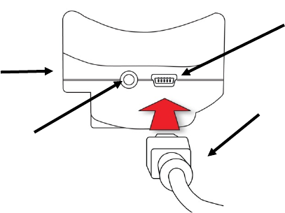
MicroRAE User’s Guide
51
13. Datalog Transfer, Monitor Configuration, and
Firmware Upgrades Via Computer
Note: Basic functionality can be adjusted via the MicroRAE’s interface, but more extensive
functionality and parameters can be adjusted using ProRAE Studio II software.
Datalogs can be downloaded from the MicroRAE to a computer, and firmware updates can be
uploaded to the MicroRAE via the USB port on the Travel Charger. Use the included Mini B USB
(5-pin)-to-USB cable to connect the Travel Charger to a computer running ProRAE Studio II
(version 1.10.0 or higher).
13.1. Downloading Datalogs And Performing PC-Based
Instrument Configuration and Firmware Upgrades
The MicroRAE communicates with a PC running ProRAE Studio II Instrument Configuration and
Data Management software to download datalogs, configure the instrument, or upload new
firmware.
The MicroRAE must be connected to a PC through the supplied Travel Charger and must be in
the PC communications mode.
1. Use the supplied PC Communications Cable (USB to mini-USB cable) to connect the
Travel Charger to a PC.
2. Turn on the MicroRAE. Make sure it is running (with the main measurement screen
showing).
3. Activate the PC communications mode on the MicroRAE by pressing [MODE] repeatedly,
starting from the main measurement screen until you reach the “Comm Mode” screen.
4. Press [Y/+]. Measurement and datalogging stop, and the instrument is now ready to
communicate with the PC. The display now says “Ready To PC”.
5. Start up the ProRAE Studio II software, enter a password, and detect the instrument
following the directions provided in the ProRAE Studio II User’s Guide.
6. Follow the instructions in the ProRAE Studio II User’s Guide to download the datalog,
configure the instrument settings, or update the MicroRAE’s firmware.
7. When you are done, press [MODE] to exit the PC communications mode on the MicroRAE.
Note: After upgrading the MicroRAE's firmware, the instruments will turn off
automatically.
Mini B USB
(5
-Pin) to
USB cable
Travel
Charger
Mini B USB
(5
-Pin) port
LED
Power
Indicator
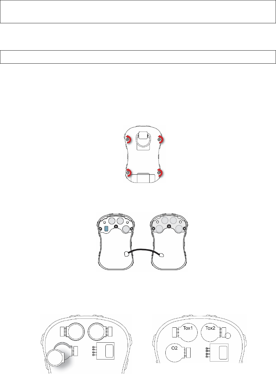
MicroRAE User’s Guide
52
14. Maintenance
The MicroRAE requires little maintenance, aside from replacing sensors.
IMPORTANT!
RAE Systems by Honeywell cannot guarantee the IP rating of an instrument that has been
opened.
14.1. Removing Sensors
WARNING! Do not replace sensors in hazardous locations.
All sensors are located inside the sensor compartment in the upper half of the MicroRAE. To
access the sensors:
1. Turn off the instrument.
2. Remove the four screws in the back of the instrument.
3. Turn the instrument over.
4. Lift off the front cover from the back of the instrument.
Caution: In some MicroRAE instruments a wire connects the buzzer in the top to the circuit board in
the bottom. Do not damage or remove it.
5. Carefully lift out each sensor you wish to inspect or replace.
Note: Oxygen and toxics sensors are labeled on their sides. The sockets are also labeled.
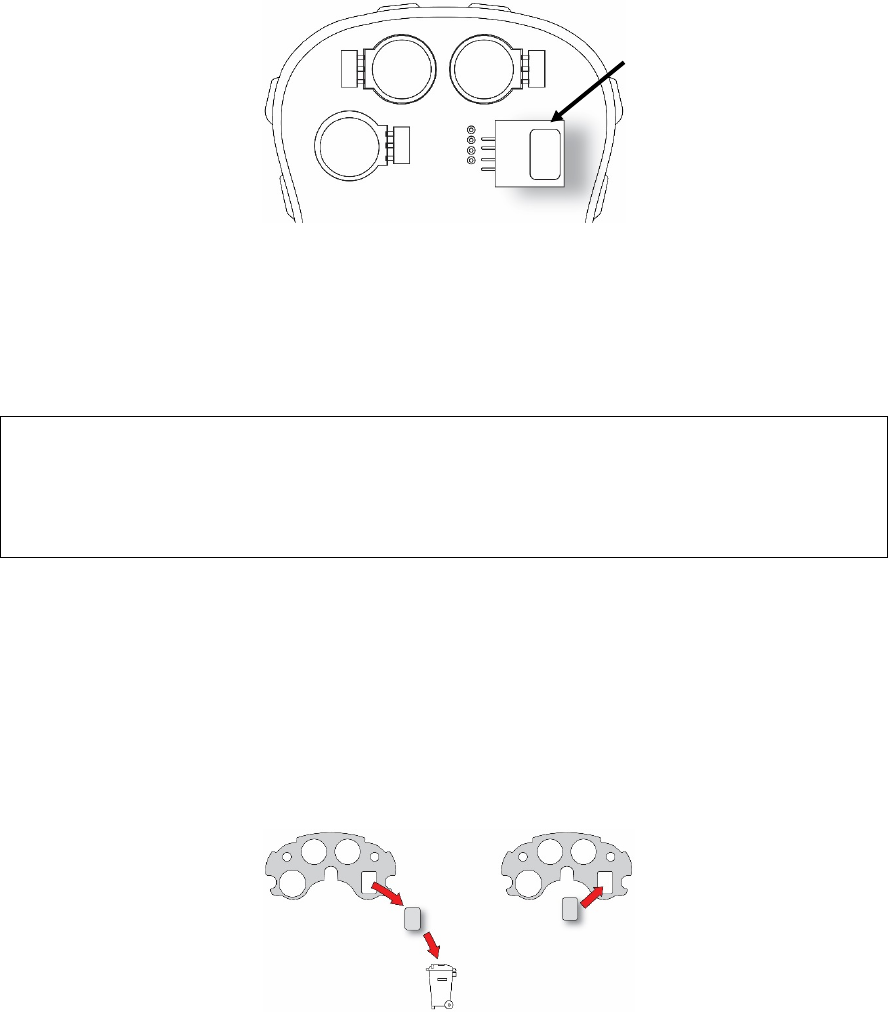
MicroRAE User’s Guide
53
The LEL sensor is square and has four pins that insert into four plated holes in the PC board.
When removing or installing an LEL sensor, lift it straight out and be careful not to bend the pins.
14.2. Replacing Sensors
1. Install the replacement sensor. Make sure the electrical contact pins are aligned with the
holes in the PC board and that the sensor is seated firmly.
2. Remove the plastic film from the top of the sensor.
3. Replace the cover and tighten the four screws.
WARNING!
It is extremely important that sensors are installed in the correct orientation.
When installing a new sensor, the plastic film should be on top of the sensor. Once the sensor is
installed, remove the plastic film.
IMPORTANT! Always perform a full calibration after replacing sensors.
14.3. Replacing The LEL Filter
If the LEL sensor appears dirty, it should be replaced with a new one (H2S filter P/N: 014-3603-
005, package of 5; or H2S & Si filter P/N: 014-3604-005, package of 5).
1. Remove the LEL filter from the gasket and dispose of it.
2. Replace the LEL sensor in its place in the gasket.
LEL
Sensor
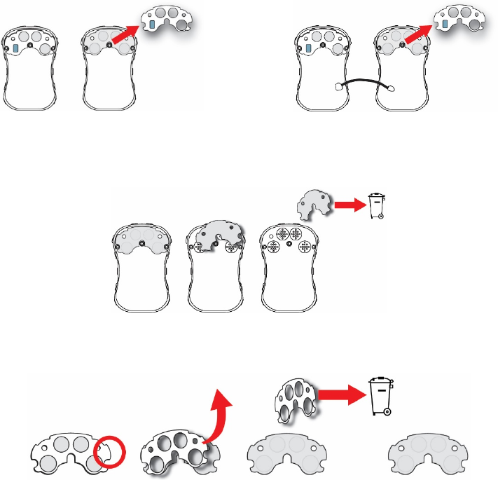
MicroRAE User’s Guide
54
14.4. Replacing The Waterproof Membrane Filter
The waterproof membrane filter (PN: M03-2007-000) is located inside the top of the case and
prevents water and dirt from entering the instrument. If the filter appears dirty or if the instrument
is having difficulty drawing in a sample, check the waterproof membrane filter for contamination,
and if necessary, replace it.
1. Make sure the MicroRAE is turned off.
2. Remove the four screws on the back to open the MicroRAE.
3. Place the top housing face-down on a flat surface. Caution: In some MicroRAE instruments a
wire connects the buzzer in the top to the circuit board in the bottom. Do not damage or remove it.
4. Remove the rubber seal and set it aside. It has a filter for the LEL sensor (blue rectangle).
Note: Because the instrument is open, this is a good time to replace the LEL filter (see page Error!
Bookmark not defined.).
5. Grip the currently installed waterproof membrane filter and pull it up. You may have to use
a tweezers to get a firm grip. (If it leaves residue, blow it out with a can of compressed air.)
Discard the used waterproof membrane filter.
6. Set a new waterproof membrane filter on a flat surface. Peel off and discard one side’s
paper covering that protects the adhesive.
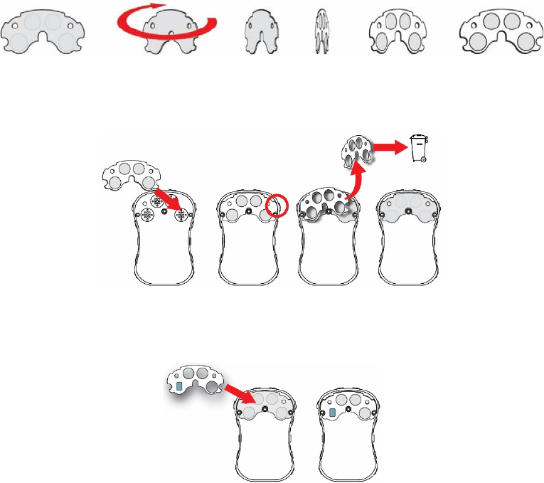
MicroRAE User’s Guide
55
7. With the paper removed from one side of the waterproof membrane filter, turn it around so
that the side with paper on it is facing you. The adhesive side is now exposed, so do not set
it down or allow it to contact other objects.
8. Carefully set the new waterproof membrane filter (PN: M03-2007-000) into the compartment, and
press it into place so that the adhesive sticks to the housing all the way around its perimeter.
9. Grasp an edge of the protective paper and peel it off. Discard it.
10. Inspect the rubber seal (PN: M03-2004-000), and if it is damaged or cracked, replace it.
11. Align the rubber seal with the LEL filter over the waterproof membrane filter. When it is
aligned, press it down to make sure it sticks to the adhesive.
12. Replace the cover and tighten the screws.
13. Turn on the instrument and calibrate it before placing it back into service.
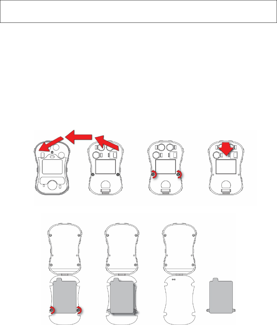
MicroRAE User’s Guide
56
14.5. Replacing The Battery
WARNING! Do not replace the battery in a hazardous location. Use only RAE Systems battery
P/N: M03-3004-000.
14.5.1 Removing The Battery
The battery is located inside the MicroRAE, attached to the backside of the printed circuit board.
To access and replace the battery:
1. After opening the instrument, lift off the front cover from the back.
2. Remove the two screws that secure the printed circuit board.
3. Tilt up the printed circuit board from the top. There is a ribbon cable connecting the
printed circuit board and the back, so be careful not to damage it.
4. Remove the two screws holding the battery in place.
5. Lift the battery straight up to remove it.
6. Properly dispose of the old battery.
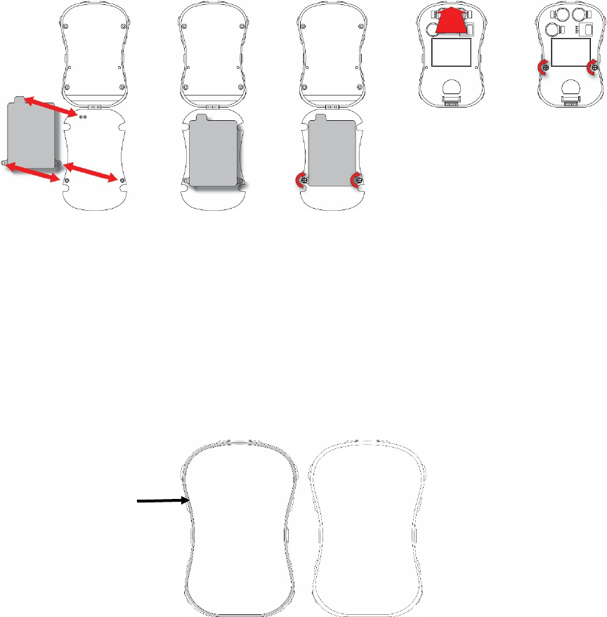
MicroRAE User’s Guide
57
14.5.2 Installing The New Battery
When you reassemble the MicroRAE, inspect for any damage and make sure the sealing rib is in
place.
1. Position the new battery so that its two screw holes are aligned over the screw holes in
the printed circuit board, and the protruding part of the battery is aligned over the two
power pins that stick up from the printed circuit board.
2. Replace the two screws to secure the battery in pace. Do not overtighten.
3. Gently flip the printed circuit board up so that it turns over and sits in the case bottom.
4. Replace the two screws to secure the printed circuit board in place. Do not overtighten.
14.6. Reassembling The MicroRAE
When you reassemble the MicroRAE, inspect for any damage and make sure the sealing rib is in
place and that you use new O-rings for the four screws. (Screws and O-rings, package of 10,
P/N: M03-3010-000.)
Important! If the housing is damaged, it should be replaced. Contact RAE Systems customer
service.
Before mating the front and back housings, make sure the Sealing Rib is in position and not
cracked, damaged, or distorted:
Sealing
Rib
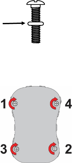
MicroRAE User’s Guide
58
The four screws that hold the housing together must have new O-rings (PN: 430-B074-060)
installed to help ensure that water and debris do not enter through the screw access points.
To prevent damage to the housing, the screw, and the O-ring, an electric screwdriver should be
set with torque less than 3kgf.cm, and a speed rate of less than 670r/min.
Tighten the screws following this order:
O-Ring
MicroRAE User’s Guide
59
15. Alarms Overview
The MicroRAE provides an unmistakable five-way alarm notification system that combines local
alarms on the device with real-time remote wireless alarm notification to enhance worker. Local
alarms include audible buzzer alarm, visible alarm via bright LED lights, vibration alarm, and an
alarm notification on the display. These can be programmed or selectively turned on or off.
15.1. Alarm Signals
During each measurement period, the gas concentration is compared with the programmed alarm
limits for Low, High, TWA and STEL alarm. If the concentration exceeds any of the preset limits,
the alarms are activated immediately to warn both the MicroRAE user and a remote safety officer
(if wireless is enabled) of the alarm condition.
In addition, the MicroRAE alarms if the battery voltage is low.
When the low battery alarm occurs, there may be approximately 10 minutes of operating time remaining.
In this case, it is recommended that you promptly charge the battery in a non-hazardous location.
Note: The default setting for the alarms is “unlatched.” To change this to latched mode, you must use
ProRAE Studio II software.

MicroRAE User’s Guide
60
15.2. Alarm Signal Summary
Alarm Summary
Alarm Type
Buzzer & LED
Display
Vibration
Reading
Backlight
Priority
Panic Alarm 4 beeps/sec “PANIC ALARM” screen 400ms On Highest
Super Alarm 4 beeps/sec “Man Down Alarm” screen 400ms - On
Man Down Alarm 3 beeps/sec “Man Down Alarm” screen 400ms - On
Man Down
Warning
2 beeps/sec “OK” screen 400ms - On
Fail 3 beeps/sec
“FAIL” screen and “ADC
Saturated (Max) or
“Sensor Fail”
400ms Blinking
reading On
Over Range 3 beeps/sec “Over” at sensor location,
ALARM icon on 400ms
Blinking
maximum
reading
On
High 3 beeps/sec
“HIGH” at sensor location,
ALARM icon on
400ms
Blinking
reading
On
Low 2 beeps/sec
“LOW” at sensor location,
ALARM icon on
400ms
Blinking
reading
On
Negative 1 beep/sec
“NEG” at sensor location,
ALARM icon on
400ms
Blinking
“0”
On
STEL 1 beep/sec
“STEL” at sensor location,
ALARM icon on
400ms
Blinking
reading
On
TWA 1 beep/sec
“TWA” at sensor location,
ALARM icon on
400ms
Blinking
reading
On
Calibration Failure
1 beep/sec
“CAL” at sensor location,
ALARM icon on
400ms
Blinking
reading
On
Bump Failure 1 beep/sec
“Bump” at sensor location,
ALARM icon on
400ms
Blinking
Reading
On
LEL failure
3 beeps/sec
“FAIL” LEL sensor on
display
400ms
-
On
Datalog Full 1 beep/sec Blinking datalog symbol 400ms Reading On
Calibration Due - “CAL” at sensor location -
Blinking
Reading
-
Bump Test Due - “Bump” at sensor location
-
Blinking
Reading
-
Battery 1 beep/min Blinking battery icon 400ms Reading Stays as is
Network Lost 1 beep/sec Blinking radio icon 400ms Reading On
Network Joined
1 beep
Radio icon
400ms
Reading
-
Comfort Beep
1 beep/min
No LED flash
- - Reading - Lowest
Notes
• “Negative” means that the reading is below zero.
• “Network Lost” means that the MicroRAE has lost wireless connectivity with its network.
• “Network Joined” means that the MicroRAE has joined a wireless network.
• “CAL” includes Span calibration failure, Zero/fresh air calibration failure.
• Zero/fresh air failure is only supported by LEL and oxygen sensors.

MicroRAE User’s Guide
61
General Alarms
15.1. Manual Alarms Test
Under Normal Operation Mode and non-alarm conditions, the buzzer (audible alarm), vibration,
visible alarms, and backlight can all be tested anytime by pressing [Y/+]. If any alarm does not
respond, connect the MicroRAE to a PC running ProRAE Studio II and check the alarm settings
to make sure all alarms are enabled. If any alarms are enabled but not functional, the instrument
should not be used. Contact RAE Systems Technical Support.
Alarm
Type
Buzzer & LED
Display
Vibrator
Reading
Backlight
Priority
Oxygen
Low Low
3
beeps/second
“LOW”
Oxygen
sensor on
display
400ms
-
On
Highest
Low Alarm
2 beeps/sec
“LOW” at
sensor
location,
ALARM
icon on
400ms
Blinking
reading
On
Confidence
LED flash
Blinking
Confidence
LED for 3
seconds
“OK” on
display
-
-
-
GPS
Offline
-
Blinking
“GPS” icon
-
-
-
Lowest
* For oxygen, “LOW Oxygen” means a concentration is lower than the low alarm limit.

MicroRAE User’s Guide
62
16. Troubleshooting
Problem
Possible Reasons & Solutions
Cannot turn on power after
charging the battery
Reasons: Defective charging circuit. Defective battery.
Solutions: Try charging the battery again. Replace
battery or charger.
Lost password
Solutions: Call Technical Support at +1 408-952-8461 or
toll-free at +1 888-723-4800
Buzzer, LED lights, and
vibration motor
inoperative
Reasons: Buzzer and/or other alarms disabled.
Bad buzzer.
Solutions: Check under “Alarm Settings” in
Programming Mode that buzzer and/or other
alarms are not turned off.
Call authorized service center.
If you need replacement parts, please contact an authorized RAE Systems distributor.
17. Diagnostic Mode
In Diagnostic Mode, the MicroRAE provides raw counts for sensor, battery, and other readings,
as well as a list of installed sensors and information about them (expiration date, serial number,
etc.). Most of these screens are useful only to service technicians. Many allow access for
changing settings.
The MicroRAE’s Diagnostic Mode can only be accessed at startup time. In Diagnostic Mode,
MicroRAE displays readings in raw counts instead of units such as parts per million (ppm) or
other units of measure.
17.1. Entering Diagnostic Mode
1. With the MicroRAE turned off, press and hold both [MODE] and [Y/+].
2. When the display turns on and the password screen appears, release the keys.
3. Enter the 4-digit password (the password is the same as the one for the Programming
Mode; the default password is 0000).
• Step from one position in the four-character string to the other by pressing [MODE].
• Press [Y/+] repeatedly to select a desired number. Numbers increase from 0 to 9.
• Once 9 is reached, pressing [Y/+] again “wraps” around back to 0.
4. When you are done, press [MODE] followed by [Y/+]. If you input the correct password,
the instrument restarts in normal reading mode.
17.2. Exiting Diagnostic Mode
1. Turn off the MicroRAE by pressing and holding [MODE]. There will be a standard shutoff
countdown.
2. When the instrument shuts off, you will be alerted. Release your finger.
Note: The next time you start MicroRAE, hold only [MODE], and it will automatically start in
Normal Mode.
MicroRAE User’s Guide
63
17.3. Navigating Diagnostic Mode
Step through Diagnostic Mode by pressing [MODE]. The first screen you see is information about
the product, including the serial number, firmware version, etc. Exit Diagnostic Mode at any time
by shutting the instrument off (hold [MODE] for the 5-second countdown).
• Instrument model name and ID number (in hexadecimal)
• Serial number
• Instrument firmware Version
• Firmware build date
• Firmware build time
• Sensors Installed
• Socket Raw Counts (for all installed sensors)
• Zero and Span raw counts for LEL sensor
• Zero and Span raw counts for O2 sensor
• Air and Span raw counts for O2 sensor
• Location 1 Zero and Span raw counts
• Location 2 Zero and Span raw counts
• LEL sensor ID and Gain (press [Y/+] to step through raw count and last calibration date
and time)
• O2 sensor ID and Gain (press [Y/+] to step through raw count and last calibration date
and time)
• Location 1ID and Gain (press [Y/+] to step through raw count and last calibration date
and time)
• Location 2 ID and Gain (press [Y/+] to step through raw count and last calibration date
and time)
• Buzzer Mode (press [Y/+] to change: 0 = silent, 1 through 7 indicates number of beeps
per second)
• Buzzer Frequency (press [Y/+] to change frequencies in 100 Hz increments)
• Battery voltage (raw count; press [Y/+]to view VRAW and voltage)
• RTC (real-time clock) shows date and time
• Ambient light sensor threshold raw count (press [Y/+] to turn backlight on/off)
• Backlight and Vibrator (press [Y/+] to toggle; BKL1 = white backlight, BKL2 = red
backlight)
• Temperature raw count and Celsius reading
• Motion (shows X, Y, and Z position; press [Y/+] to change window, warning time, and
threshold value)
• Runtime
• LCD contrast (press [Y/+] to change)
• LCD Test (press [Y/+] to show entire display)
• BLE (Bluetooth Low Power) power on (on/off status, press [Y/+] for MAC address)
• GPS Power (if GPS is installed)
• Wi-Fi (press [Y/+] to step through settings)
• GPS longitude and latitude (press[Y/+] to show status and number of satellites
• Mesh module firmware version and build date (press [Y/+] to show ID, PANID, Press[Y/+]
to continue to show PID and channel, and press [Y/+] again to show region and radio
type)
• Communication – Enter communication mode with computer (press [Y/+] to enter; press
[MODE] to exit)

MicroRAE User’s Guide
64
18. Editing Features
Some features can be turned on or off or edited directly on the MicroRAE, some can only be
accessed through ProRAE Studio II, and some can be accessed and changed through both. The
table below shows where features can be accessed.
Feature
MicroRAE
ProRAE Studio II
Single Bump
Single Zero
Single Span
Multi Bump
Fresh Air Calibration
Multi Span
Set LEL Calibration Gas
Set Span
Sensor On/Off
Set LEL Measurement Gas
Set Alarm Limits
Set Alarm Mode
Alarm Settings
Comfort Beep
Man Down Alarm On/Off
Man Down Window Time
Man Down Warning Time
Man Down Motion Sensitivity
Man Down Falldown Sensitivity
Man Down Alarm Warning Time
Clear Datalog
Datalog Interval
Datalog Sensor Selection
Datalog Data Selection
Datalog Type
Datalog Action When Full
Glance Mode Enable
Set Date
Set Time
Backlight
Set Site ID
Set User ID
User Mode
Zero At Start
Radio On/Off
Set PAN ID
Set Channel
Join Network
Set Wireless Interval
Off Network Alarm
Wireless Factory Reset
Continued on next page

MicroRAE User’s Guide
65
Editing Features, continued
Feature
MicroRAE
ProRAE Studio II
GPS On/Off
GPS Recover Mode Period
BLE On/Off
Wi-Fi On/Off
Set Access Point SSID
Set Access Point Password
DHCP Enable
Set Server IP Address
Set Server Port
Confidence LED interval
Get/Set bump test date and interval
Get/Set calibration test date and interval
Get/Set sensor maintenance
Get/Set sensor to log
Set Glance Mode screen
Roaming On/Off
GPS Search Mode Period
Get BLE MAC address
Get/Set BLE PIN code
Set Wi-Fi MAC address
Get/Set Wi-Fi message
Get gas library information
Get/Set custom gas list
Get/Set password
Get last run time
Get/Set LCD contrast

MicroRAE User’s Guide
66
19. Specifications
Instrument Specifications
Size
4.6" x 3.0" x 1.1" (117 mm x 76 mm x 27 mm)
Weight
7 oz (200 g)
Sensors
Four sensors, including electrochemicals for toxics and oxygen, combustible LEL
Battery Options
Rechargeable Li-ion: 15 hours continuous without wireless and no alarms;
12 hours continuous with wireless and no alarms
Note: All battery specifications at 20° C; lower temperatures might affect runtime.
Display
• Monochrome graphic display with backlighting (activated automatically in dim
ambient lighting conditions, when monitor is in alarm, or with a key press);
backlight can be white or red (selectable)
Display
Readout
• Real-time reading of gas concentrations; battery status; datalogging on/off; wireless
on/off and wireless reception quality.
• STEL, TWA, peak, and minimum values
• Man Down and policy enforcement indicators
• GPS quality indicator (if GPS equipped)
Keypad
2 operation and programming keys (MODE and Y/+)
Sampling
Diffusion
Calibration
Manual
Alarms
• Wireless remote alarm notification; audible, vibration,
visible (flashing bright red LEDs), and on-screen indication of alarm conditions
• Man Down Alarm with real-time remote wireless notification
Datalogging
• Continuous datalogging (six months for four sensors at 1-minute intervals, 24/7)
• User-configurable datalogging interval (from 1 to 3,600 seconds)
Communication
and
Data Download
• Data download and instrument set-up and upgrades on PC via charging and Travel
Charger
• Wireless data and status transmission via built-in RF modem (optional)
Wireless
Connectivity
BLE (Bluetooth Low Energy) plus optional RAE Systems Dedicated Wireless Network
and closed-loop systems or Wi-Fi (b/g/n)
Wireless
Frequency
ISM license-free band, IEEE 802.15.4 Sub 1 GHz, IEEE 802.11 bands b/n/g 2.4 GHz
Wireless
Approvals
FCC Part15, CE R&TTE, ANATEL (Contact us for wireless approval availability,
country-specific)
Wireless Range
(Typical)
EchoView Host & MicroRAE: Line of sight >200m (650 ft), receiving data >80%
ProRAE Guardian & Mesh Reader & MicroRAE: Line of sight >200m (650 ft), receiving data
>80%
ProRAE Guardian & RAELink3 & MicroRAE: Line of sight >100m (330 ft), receiving
data >80%
Continued
MicroRAE User’s Guide
67
Instrument Specifications
continued
Operating
Temperature
-4° to 140° F (-20° to 60° C)
Humidity
0% to 95% relative humidity (non-condensing)
IP Rating
IP-67
Hazardous
Location
Approvals
USA and Canada: classified for use in Class I, Division 1,
Groups A, B, C and D T-Code T4
Global: IECEx: Ex ia d IIC T4 Gb; Ex ia I Ma
Europe: ATEX: II 2G Ex ia d IIC T4 Gb; I M1 Ex ia I Ma
CE Compliance
(European
Conformity)
2004/108/EC (EMC)
1999/5/EC (Radio)
94/9/EC (ATEX)
FCC Compliance
FCC Part 15
Languages
English
Warranty
• Two years on LEL, CO, H
2
S, and O
2
sensors
• One year on other sensors
Specifications are subject to change.
Sensor Specifications
Combustible Sensor
Range
Resolution
Operating Temperature
Catalytic bead LEL
0 to 100% LEL
1% LEL
-4° to 122° F (-20° to 50° C)
Electrochemical Sensors
Range
Resolution
Operating Temperature
Carbon Monoxide (CO)
0 to 250 ppm
251 to 1000 ppm
1 ppm
3 ppm
-4° to 122° F (-20° to 50° C)
Hydrogen Cyanide (HCN)
0 to 50 ppm
0.2 ppm
-4° to 122° F (-20° to 50° C)
Oxygen (O2)
0 to 30% Vol.
0.1% Vol.
-4° to 122° F (-20° to 50° C)
Hydrogen Sulfide (H
2
S)
0 to 50 ppm
51 to 100 ppm
0.1 ppm
1 ppm
-4° to 122° F (-20° to 50° C)
All specifications are subject to change without notice.
LEL Range, Resolution & Response Time
Range
0 to 100% LEL
Resolution
1%
Response Time:
T90 < 30 sec.
Caution:
• Refer to RAE Systems Technical Note TN-114 for LEL sensor cross-sensitivities.
• Refer to RAE Systems Technical Note TN-144 for LEL sensor poisoning.
MicroRAE User’s Guide
68
Year Of Manufacture
To identify the year and month of manufacture, refer to the two digit marking placed adjacent to
the serial number on the instrument label according to the following table:
Year
First digit
Year code
Month
Second digit
Month code
2014
R
January
1
2015
S
February
2
2016
T
March
3
2017
U
April
4
2018
V
May
5
2019
W
June
6
2020
A
July
7
2021
B
August
8
2022
C
September
9
2023
D
October
A
2024
E
November
B
2025
F
December
C
Example: “RA” indicates that the monitor is manufactured in the month of October in the year
2014.
Model Designations And Base Configuration
Model Name
Configuration
PGM-2600
MicroRAE with BLE
PGM-2601
MicroRAE with BLE/Mesh Radio
PGM-2602
MicroRAE with BLE/Wi-Fi
Standard Span Values For Sensors
Sensor
Standard Span Values
CO
50 ppm
H2S
10 ppm
OXY
18.0 %
LEL
50 %LEL Methane
HCN
10 ppm

MicroRAE User’s Guide
69
Sensor Parameters Edit Range
Parameter
Unit
Minimum
Maximum
Default
CO Span
ppm
1
500
50
CO Range
ppm
1
1000
N/A
CO Low
ppm
1
1000
35
CO High
ppm
1
1000
200
CO STEL
ppm
1
1000
100
CO TWA
ppm
1
1000
35
H2S Span
ppm
1
100
10
H2S Range
ppm
1
100
N/A
H2S Low
ppm
1
100
10
H2S High
ppm
1
100
20
H2S STEL
ppm
1
100
15
H2S TWA
ppm
1
100
10
LEL Span
%LEL
1
100
50
LEL Range
%LEL
1
100
N/A
LEL Low
%LEL
1
100
10
LEL High
%LEL
1
100
20
O2 Span
%
1
30
18
O2 Range
%
1
30
N/A
O2 Low
%
1
30
19.5
O2 High
%
1
30
23.5
O2 Low Low
%
1
30
17
HCN Span
ppm
1
50
10
HCN Range
ppm
1
50
N/A
HCN Low
ppm
1
50
4.7
HCN High
ppm
1
50
25
20. Upgrading A MicroRAE’s Bluetooth Driver To
BLE For Safety Communicator
20.1. Introduction
This procedure is for MicroRAE instruments originally received with Firmware version lower
than v1.10 (shipped before February 2017). It upgrades the instrument’s Bluetooth protocol
to BLE (Bluetooth Low Energy) for compatibility with Safety Communicator. The MicroRAE
will only operate with Safety Communicator if it is running Firmware version higher than
version 1.10.
20.2. Connect The MicroRAE To A PC
Note: The MicroRAE must be connected to a PC through the supplied Travel Charger and
must be in the PC communications mode.
1. Attach the Travel Charger to the MicroRAE.
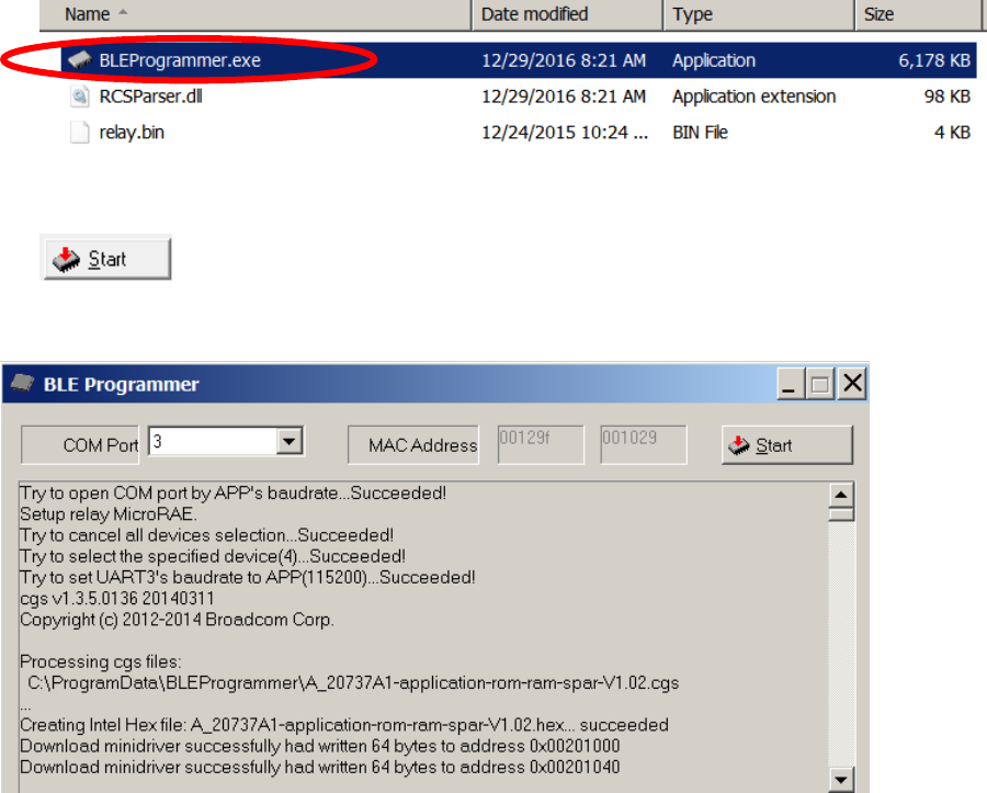
MicroRAE User’s Guide
70
2. Use the supplied PC Communications Cable (USB to mini-USB cable) to connect the
Travel Charger to a PC.
3. Turn on the MicroRAE. Make sure it is running (with the main measurement screen
showing).
4. Activate the PC communications mode on the MicroRAE by pressing [MODE]
repeatedly, starting from the main measurement screen until you reach the “Comm
Mode” screen.
5. Press [Y/+]. Measurement and datalogging stop, and the instrument is now ready to
communicate with the PC. The display now says “Ready To PC”.
20.3. Download And Start BLE Programmer
1. Download a file called BLE Programmer V1.0.2.zip (available at
https://www.raesystems.com/customer-care/firmware-updates/ble-updater-microrae) to
a computer that is connected to your smartphone via a USB cable.
2. Unzip (uncompress) the file, which creates a folder.
3. Open the folder.
4. Click on the file named “BLEProgrammer.exe”.
5. Click “Start” to start the programming:
Processing begins, and this screen is shown:
Note: Make sure the COM Port number is correct. If it is not, the procedure fails.
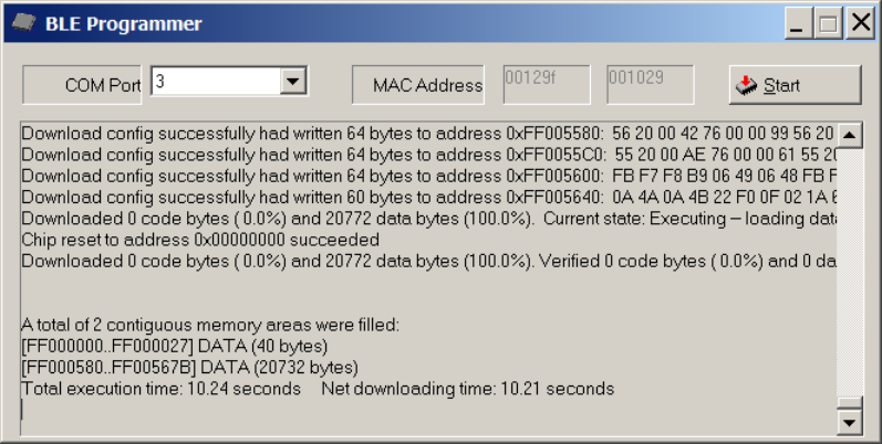
MicroRAE User’s Guide
71
When the procedure is finished, the screen looks like this:
1. Click the “X” in the upper right corner to close the window.
2. When you are done, press [MODE] on the MicroRAE to exit the PC communications
mode.
Shut off the MicroRAE, and then restart it. Safety Communicator should now be able to
communicate with the MicroRAE.
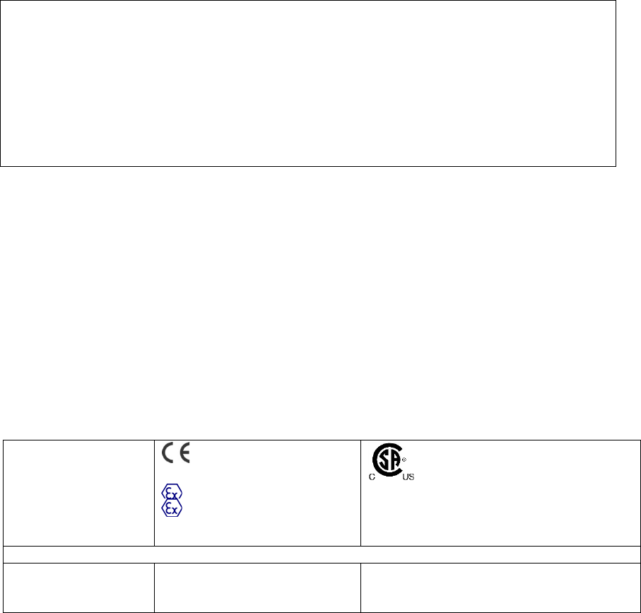
MicroRAE User’s Guide
72
21. Controlled Part of the Manual for PGM-26XX
SAFETY INSTRUCTIONS
Read Before Operating
This Manual must be carefully read by all individuals who have or will have the responsibility of
using, maintaining, or servicing this product. The product will perform as designed only if it is
used, maintained, and serviced in accordance with the manufacturer’s instructions. The user
should understand how to set the correct parameters and interpret the obtained results.
FOR SAFETY REASONS, THIS EQUIPMENT MUST BE OPERATED AND SERVICED BY
QUALIFIED PERSONNEL ONLY.
CAUTION!
The PGM-26XX shall only be charged using a charger specifically supplied for use with the unit
(for example part number 3A-066WPxx or 3A-401WP12, manufactured by ENG Electric),
approved as SELV or Class 2 equipment against IEC 60950 or an equivalent IEC standard. The
maximum voltage from the charger shall not exceed 6.0 VDC.
Likewise, any data download device connected to the PGM-26XX shall also be approved SELV
or Class 2 equipment.
Use of non-RAE Systems components will void the warranty and can compromise the safe
performance of this product.
PGM26XX Marking
The PGM-26XX is certified according to the IECEx scheme, ATEX and CSA for US and Canada
as protected by intrinsic safety.
The PGM-26XX is certified according to the IECEx scheme, ATEX and CSA for US and Canada
under the intrinsic safety method of protection.
The PGM-26XX is marked with the following information:
RAE SYSTEMS
1349 Moffett Park Dr.
Sunnyvale, CA 94089 USA
Type PGM-26XX
Serial No/barcode: XXXX-XXXX-XX
IECEx SIR 15.0039X
Ex ia d IIC T4 Gb
Ex ia I Ma
0575
SIRA 15 ATEX 2080X
II 2G Ex ia d IIC T4 Gb
I M1 EX ia I Ma
Cl. I Dv. 1, Grps A,B,C,D T-Code T4.
C22.2 No.152-M1984
ANSI/ISA-12.13.01-2000
Intrinsically safe/Sécurité intrinséque
Applied standards (ATEX-IECEx)
IEC 60079-0:2011
IEC 60079-1:2014-06
IEC 60079-11:2011
EN 60079-0:2012/A11:2013
EN 60079-1:2014
EN 60079-11:2012
See list for applied requirements for
cCSAus in the table below.

MicroRAE User’s Guide
73
APPLICABLE REQUIREMENTS (cCSAus)
CAN/CSA-C22.2 No. 60079-0:2011
(IEC 60079-0:2007, MOD)
Explosive atmospheres — Part 0: Equipment — General
requirements
CAN/CSA-C22.2 No. 60079-11:2014
(IEC 60079-11:2011, MOD)
Explosive atmospheres — Part 11: Equipment protection by
intrinsic
safety “i”
CAN/CSA-C22.2 No. 30-M1986
Explosion-Proof Enclosures for Use in Class I Hazardous
Locations
CAN/CSA-C22.2 No. 152-M1984
Combustible Gas Detection Instruments
CAN/CSA C22.2 No. 61010-1-12
Safety Requirements for Electrical Equipment for Measurement,
Control, and Laboratory Use - Part 1: General Requirements -
Third Edition
UL 60079-0:2013 (6th Ed.)
Explosive atmospheres — Part 0: Equipment — General
requirements
UL 60079-11:2013 (6th Ed.)
Explosive atmospheres — Part 11: Equipment protection by
intrinsic
safety “i”
UL 913 (7th Ed.)
Intrinsically Safe Apparatus and Associated Apparatus for Use in
Class I, II and III, Division 1, Hazardous Locations
UL 1203 (4th Ed.)
Explosion-Proof and Dust-Ignition-Proof Electrical Equipment for
Use in Hazardous (Classified) Locations
ANSI/ISA 12.13.01-2000
Performance Requirements for Combustible Gas Detectors
ANSI/ISA-61010-1 (3rd Ed.)
Safety Requirements for Electrical Equipment for Measurement,
Control, and Laboratory Use - Part 1: General Requirements -
Third Edition
-20º C < Tamb < +60º C;
Um: 6V
Battery pack: M03-3004-000
Warning: Substitution of components may impact intrinsic safety
Avertissement: La substitution de composants peut compromettre la securité intrinsèque
CAUTION: READ AND UNDERSTAND INSTRUCTION MANUAL BEFORE OPERATING OR
SERVICING
ATTENTION: LIRE ET COMPRENDRE MANUEL D’INSTRUCTIONS AVANT D’UTILISER OU
SERVICE
MicroRAE User’s Guide
74
Operation Area and Conditions
Hazardous Areas classified by Zones
PGM-26XX are intended to be used in hazardous areas classified Zone 1 or Zone 2 within the
temperature range of -20ºC to +60ºC, where gases of explosion groups IIA, IIB or IIC and T4
may be present, and in underground mines endangered by firedamp.
Hazardous Areas classified by Divisions
PGM-26XX is intended to be used in hazardous areas classified for Class I Div. 1 or 2, within
the temperature range of -20º C to +60º C, where gases of explosion groups A, B, C or D and
temperature code T4 may be present.
Instruction For Safe Use
WARNING: Read and understand instruction manual before operation or servicing.
AVERTISSEMENT: Lisez et comprenez le manual d’instructions avant d’utiliser ou service.
WARNING: Substitution of components may impact intrinsic safety.
AVERTISSEMENT: La substitution de composants peut compromettre la sécurité intrinsèque
WARNING: To prevent ignition of a hazardous atmosphere, batteries must only be charged in an
area known to be non-hazardous. Um = 6.0V. Use only approved charger/ AVERTISSEMENT:
Afin de prevenir l’inflammation d’atmosphères dangereuse, ne charger le jeu de batteries que
dans des emplacement designés non dangereux. Um = 6V Utilisez uniquement un chargeur
approuvé.
Only use approved battery pack: M03-3004-000
Only charge the battery in safe area in the ambient temperature range 0°C ≤ Tamb ≤ 40°C
EMI may cause mis-operations.
Use In Hazardous Areas
Equipment intended for use in explosive atmospheres and which has been assessed and certified
according to international regulations may be used only under specified conditions. The
components may not be modified in any way.
The appropriate regulations for service and repair must be properly observed during such
activities.

MicroRAE User’s Guide
75
Year of manufacture
To identify the year and month of manufacture, refer to the two digit marking placed adjacent to
the serial number on the instrument label according to the following table:
Year
First digit
Year code
Month
Second digit
Month code
2014
R
January
1
2015
S
February
2
2016
T
March
3
2017
U
April
4
2018
V
May
5
2019
W
June
6
2020
A
July
7
2021
B
August
8
2022
C
September
9
2023
D
October
A
2024
E
November
B
2025
F
December
C
E.G.: “RA” indicates that the monitor is manufactured in the month of October in the year 2014.
MicroRAE User’s Guide
76
22. Technical Support
To contact RAE Systems Technical Support:
Monday through Friday, 7:00AM to 5:00PM Pacific (US) Time
Phone (toll-free): +1 877-723-2878
Phone: +1 408-952-8200
Fax: +1 408-952-8480
Email: RAE-tech@honeywell.com
23. RAE Systems Contacts
RAE Systems by Honeywell World Headquarters
1349 Moffett Park Dr.
Sunnyvale, CA 94089 USA
Phone: +1 888-723-4800
E-mail: RAE-tech@honeywell.com
Web Site: www.raesystems.com
Training
Phone: +1 408-952-8260
Email: training@raesystems.com

For more information
www.honeywellanalytics.com
www.raesystems.com
Rev. E
June 2018
P/N M03-4001-000
Europe, Middle East, Africa
Life Safety Distribution GmbH
Tel: 00800 333 222 44 (Freephone number)
Tel: +41 44 943 4380 (Alternative number)
Fax: 00800 333 222 55
Middle East Tel: +971 4 450 5800
(Fixed Gas Detection)
Middle East Tel: +971 4 450 5852
(Portable Gas Detection)
gasdetection@honeywell.com
Americas
Honeywell Analytics
Distribution Inc.
Tel: +1 888 749 8878
Fax: +1 817 274 8321
detectgas@honeywell.com
Honeywell RAE Systems
Phone: 408 952 8200
Toll Free: 1 888 723 4800
Fax: 408 952 8480
Asia Pacific
Honeywell Analytics Asia Pacific
Tel: +82 (0) 2 6909 0300
Fax: +82 (0) 2 2025 0328
India Tel: +91 124 4752700
analytics.ap@honeywell.com
Technical Services
EMEA: HAexpert@honeywell.com
US: ha.us.service@honeywell.com
AP: ha.ap.service@honeywell.com