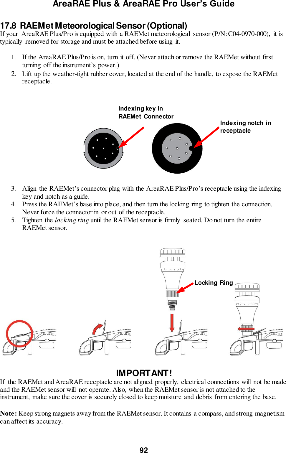
RAE Systems 6560A PGM-6560A,PGM-6520A User Manual AreaRAE User s Guide
RAE Systems, Inc PGM-6560A,PGM-6520A AreaRAE User s Guide
UserManual.wiki
>
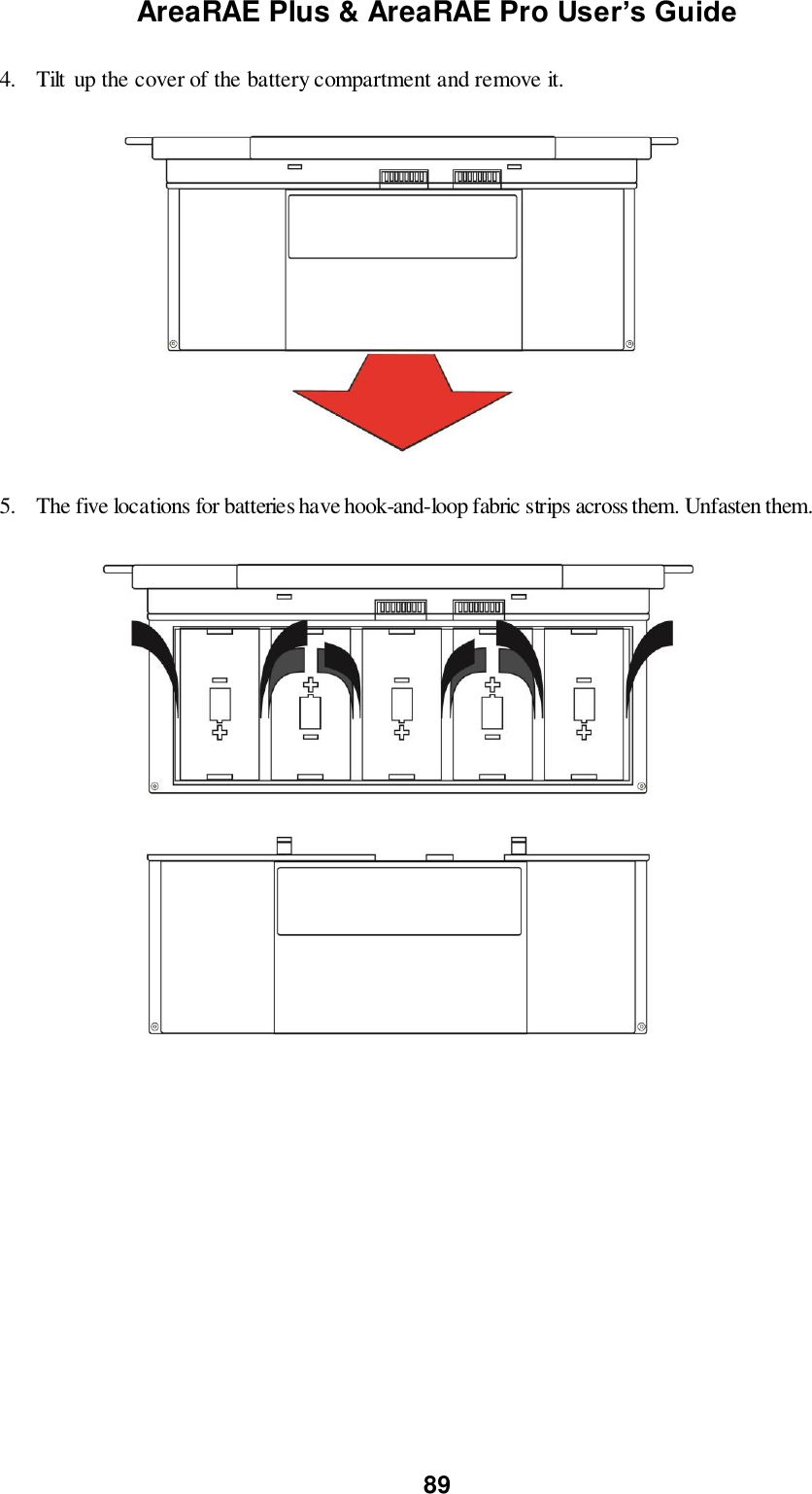
RAE Systems
>
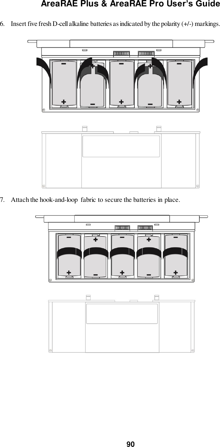
6560A User Manual
user manual_REV1
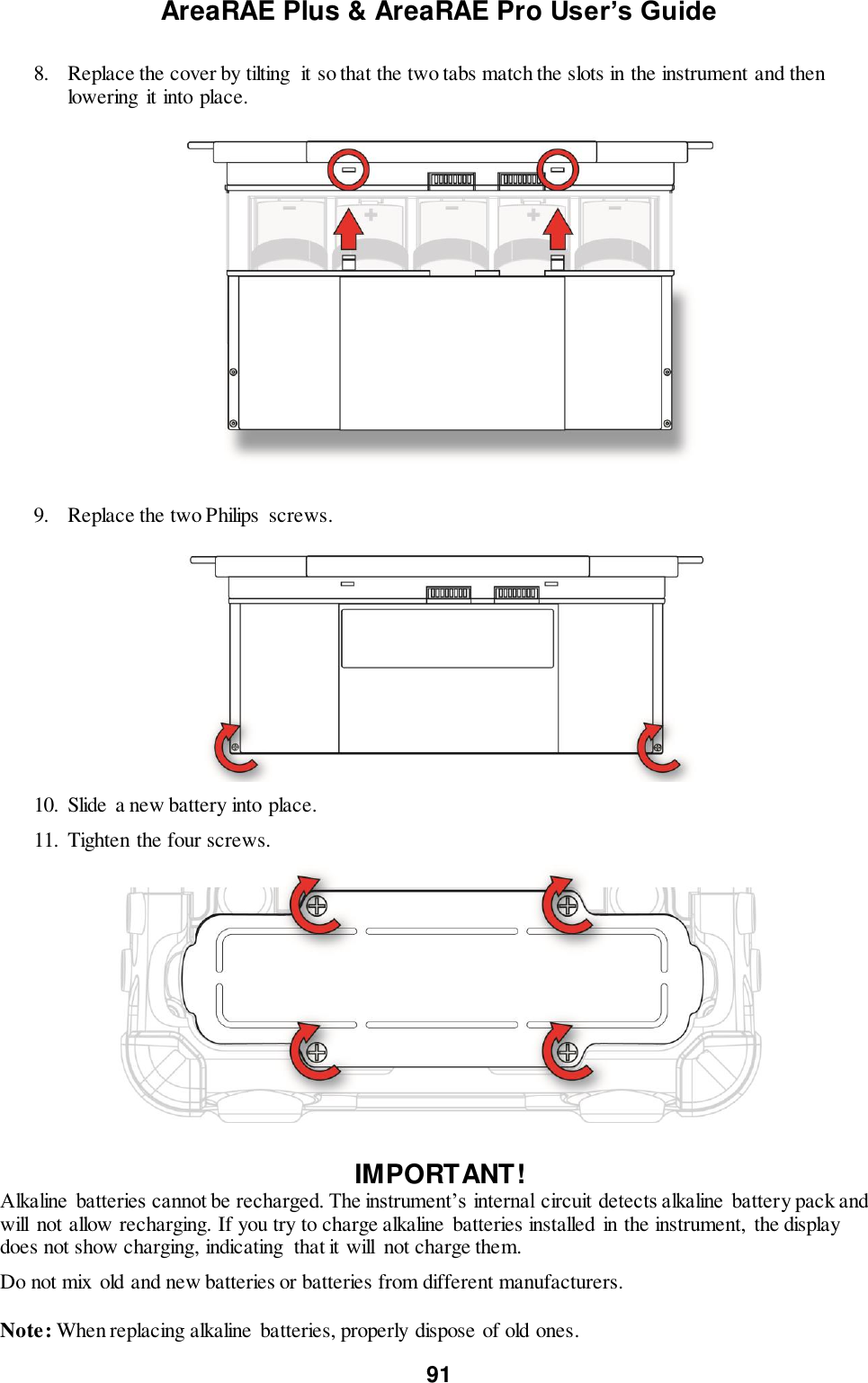
Navigation menu
Upload a User Manual
Namespaces
Wiki Guide
HTML
PDF
Info
Views
User Manual
Discussion / Help
Navigation
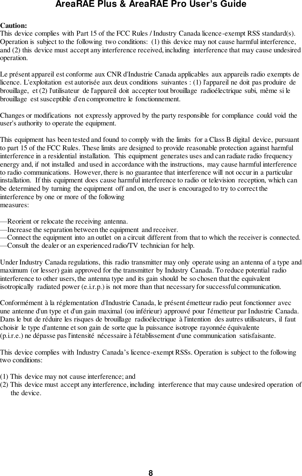
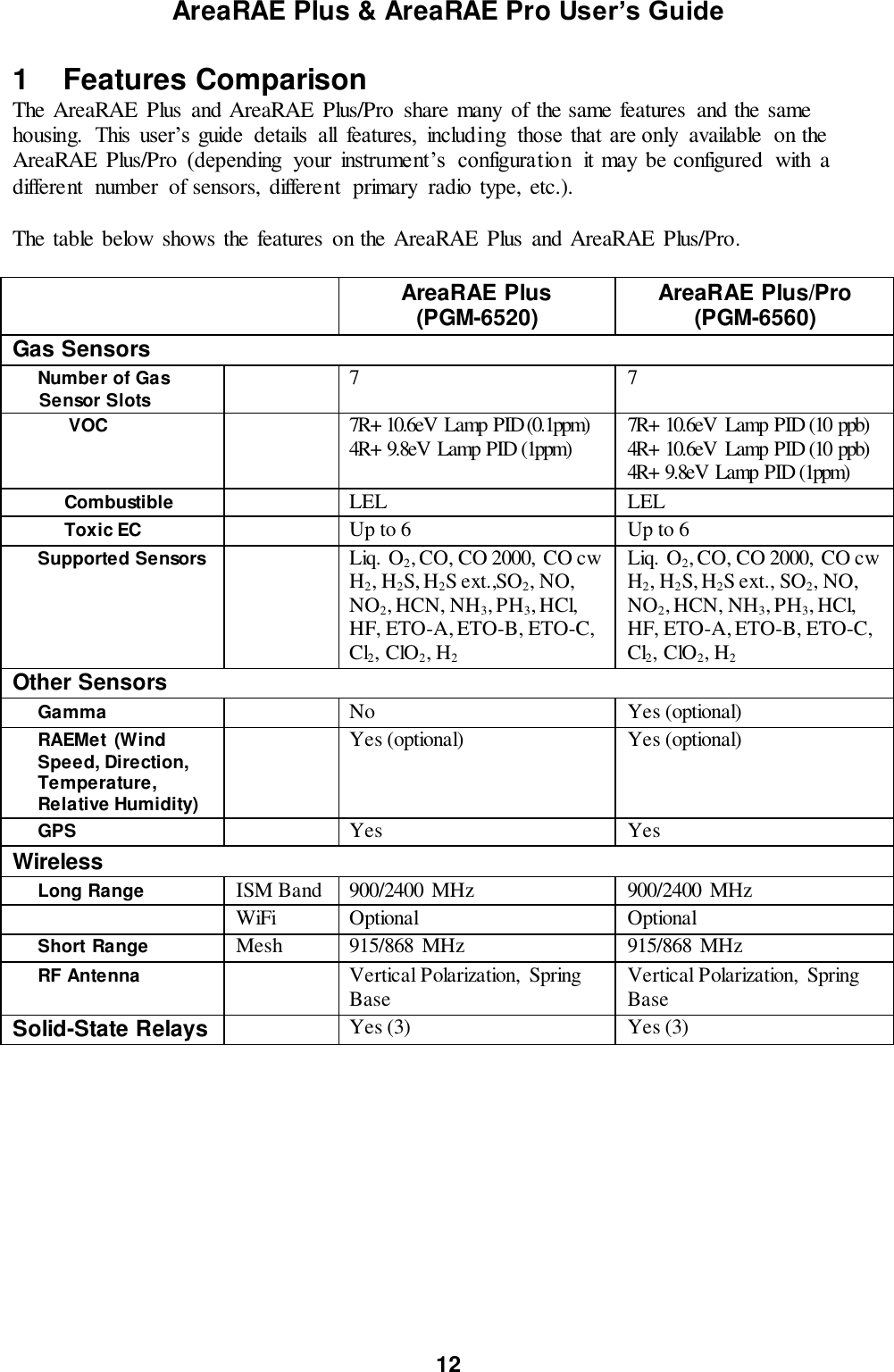
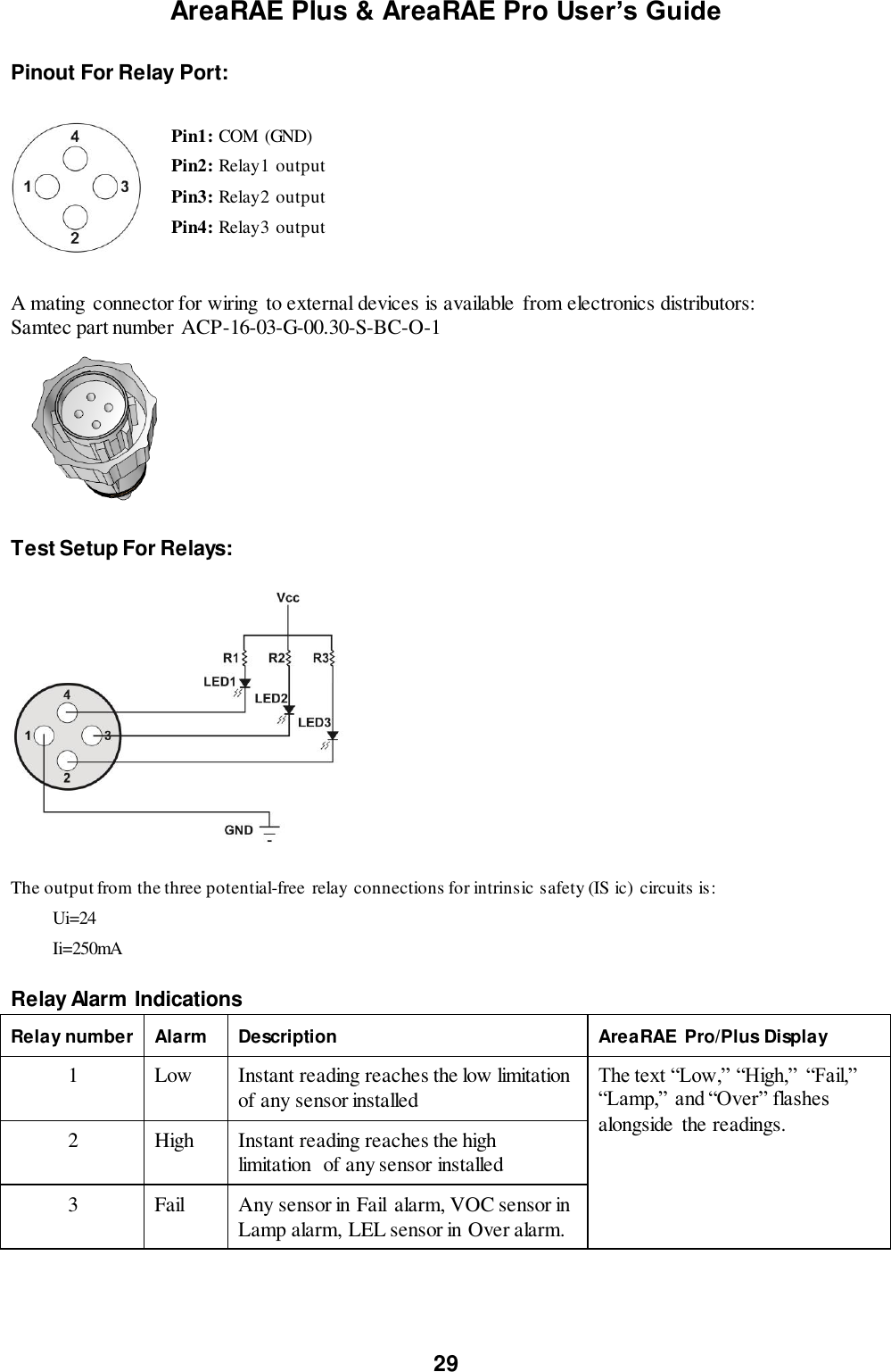
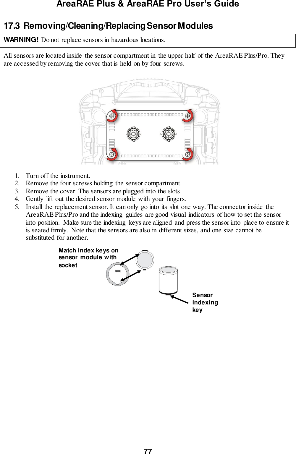
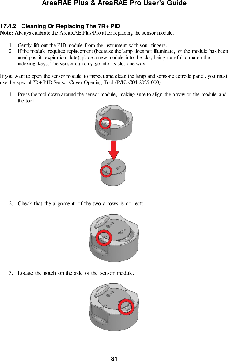
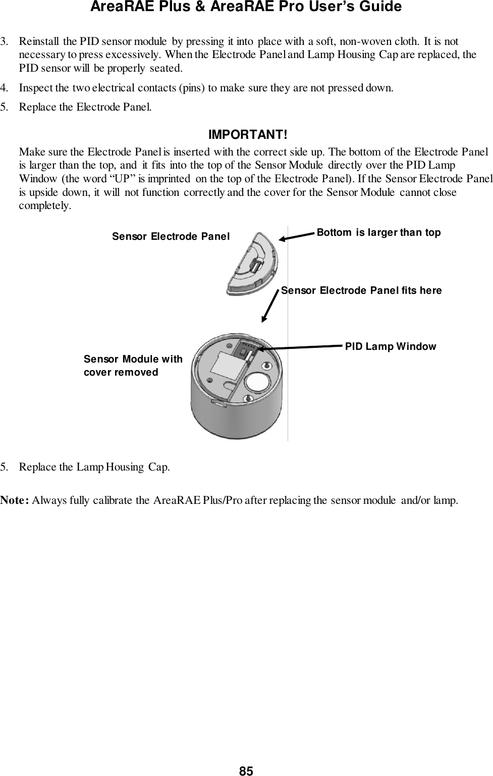
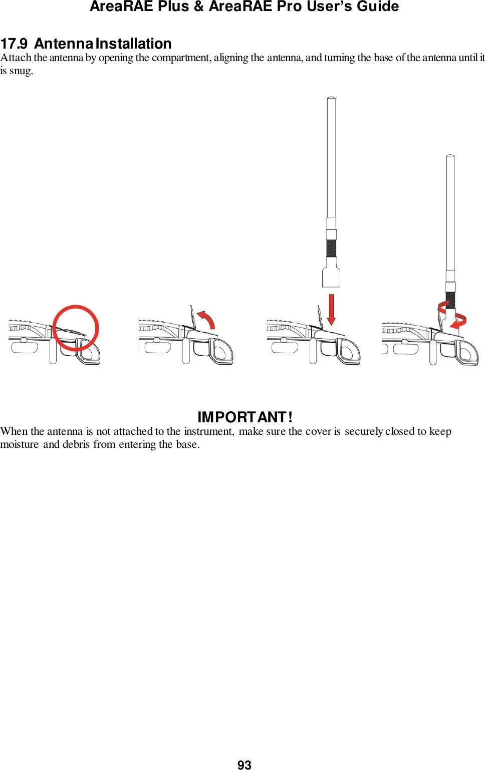
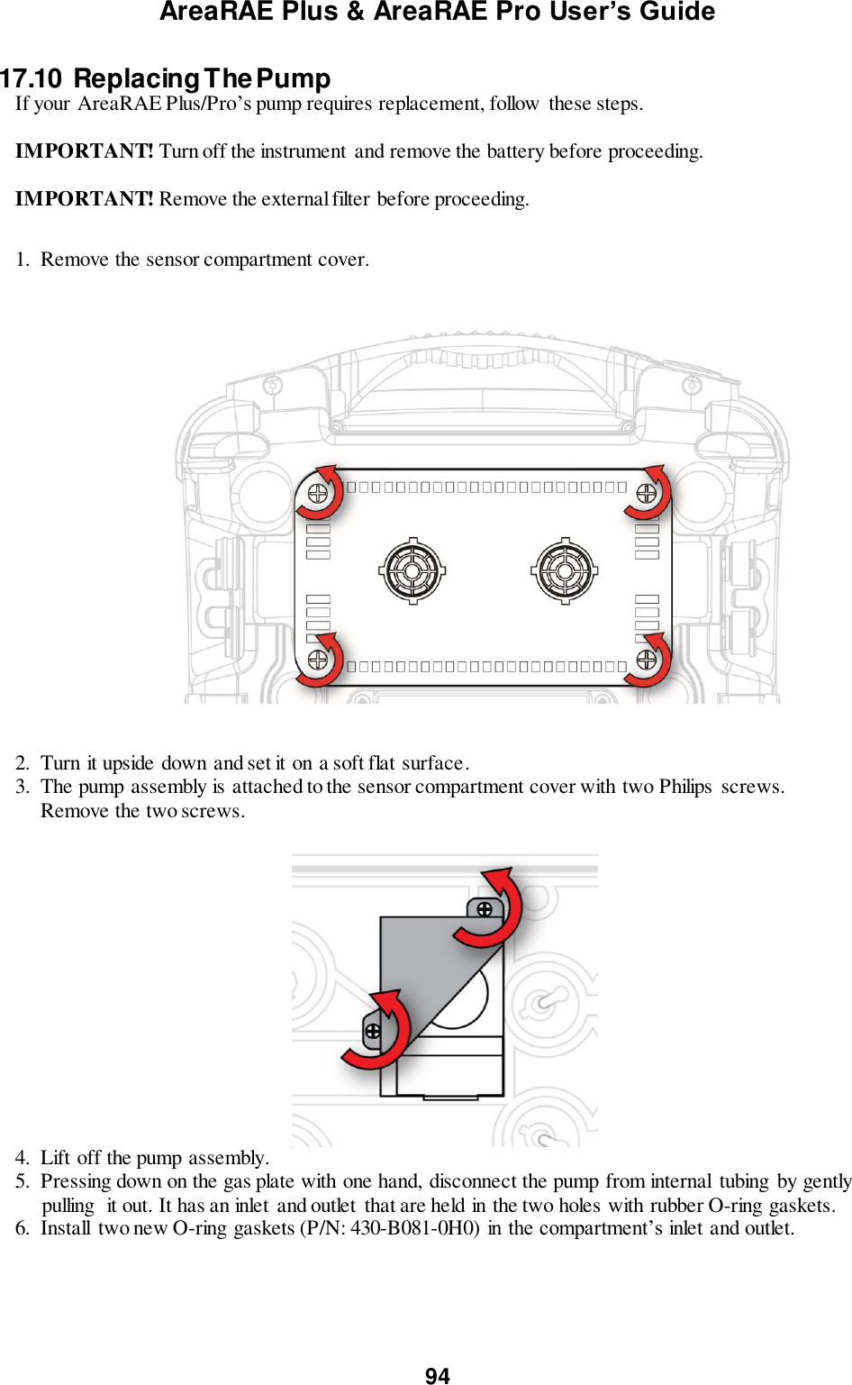
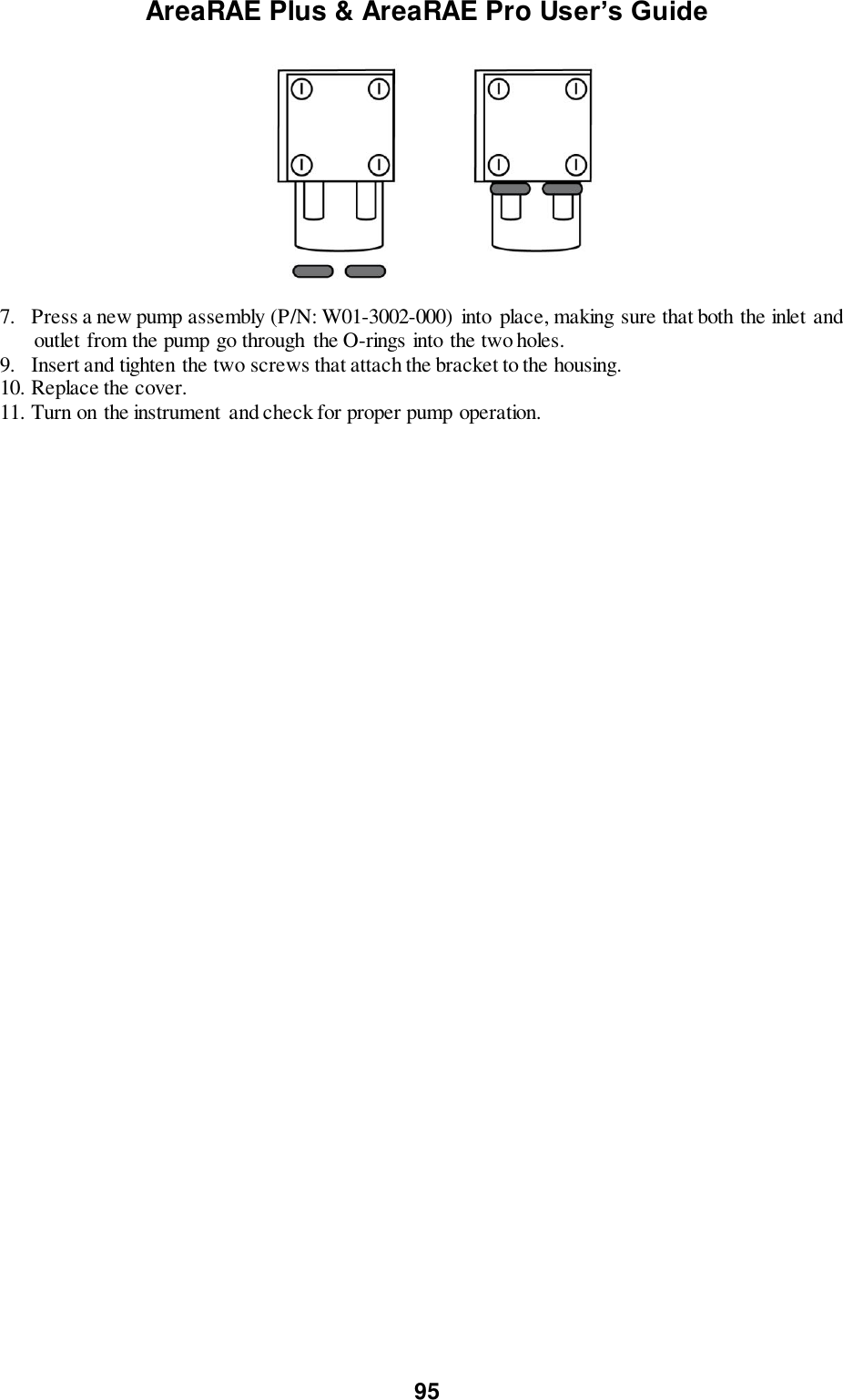
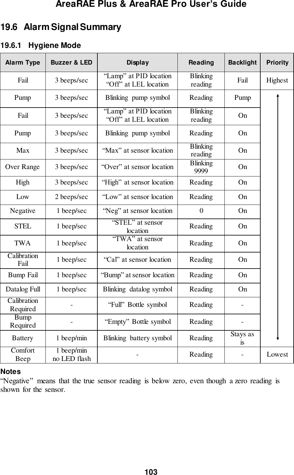
![AreaRAE Plus & AreaRAE Pro User’s Guide 7 CAUTION! TheAreaRAE, PGM-65XX shall only be charged using a charger specifically supplied for use with the unit with a mximum output voltage of 17V. Use of non-RAE Systems components will void the warranty and can compromise the safe performance of this product. MARKING The PGM-65XX is certified according to the IECEx scheme, ATEX and CSA for US and Canada under the non-sparking safety method of protection. The PGM-65XX is marked with the following information: RAE SYSTEMS 3775 N. 1st. St., San Jose CA 95134, USA Type PGM-65XX. Serial No/barcode: XXXX-XXXX-XX IECEx XXX15.XXXX Ex ic nA [ic] IIC T4 Gc XXX 15 ATEX XXXX II 3G Ex ic nA [ic] IIC T4 Gc Cl.I Dv 2, Grps A,B,C,D T-Code T4. C22.2 No.152-M1984 ANSI/ISA-12.13.01-2013 -20º C < Tamb < +50º C; Um:17V RAEMet connection: Uo: 5.2V, Po: 0.788W, Lo:198uH, Co:1000μF SSRelay connection: Ui: 24V, Ii: 250mA Battery pack: W01-3007-000 CAUTION: READ AND UNDERSTAND INSTRUCTION MANUAL BEFORE OPERATING OR SERVICING ATTENTION: LIRE ET COMPRENDRE MANUEL D’INSTRUCTIONS AVANT D’UTILISER OU SERVICE. FCC Part 15 Statement This device complies with Part 15 of the FCC rules. Operation is subject to the following two conditions: (1) This device may not cause harmful interference, and (2) this device must accept any interference received, including interference that may cause undesired operation.](https://usermanual.wiki/RAE-Systems/6560A/User-Guide-3055882-Page-7.png)
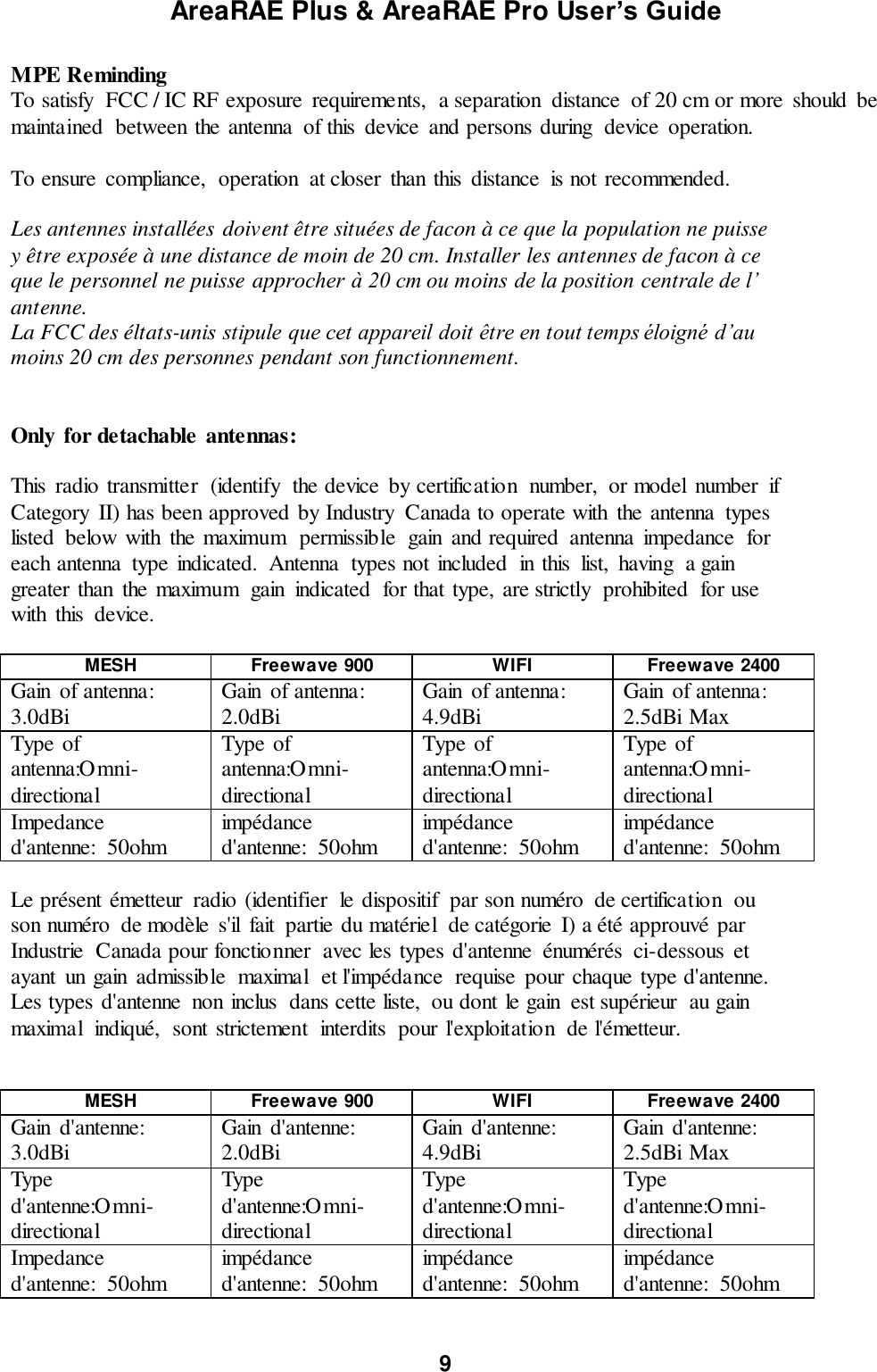
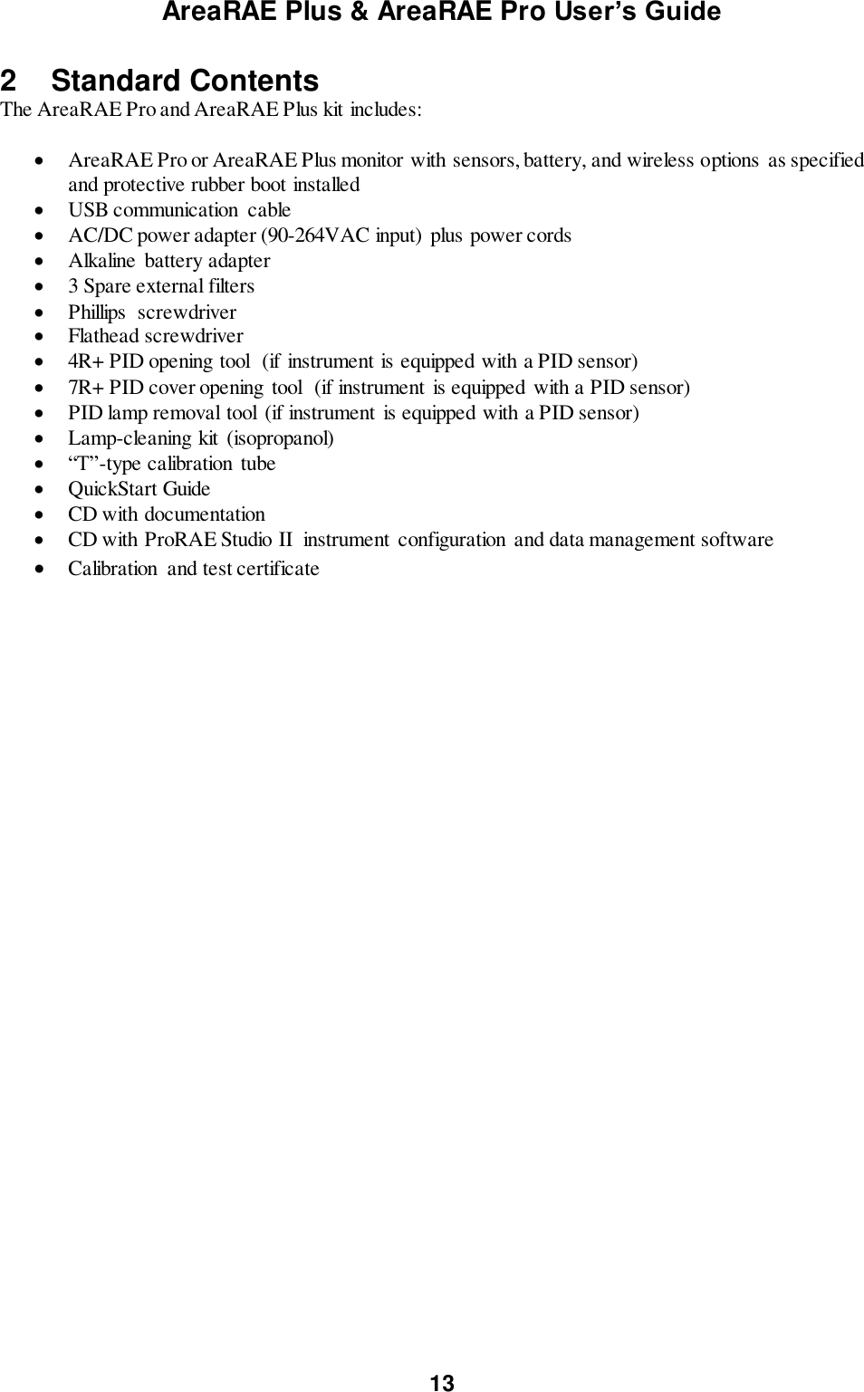
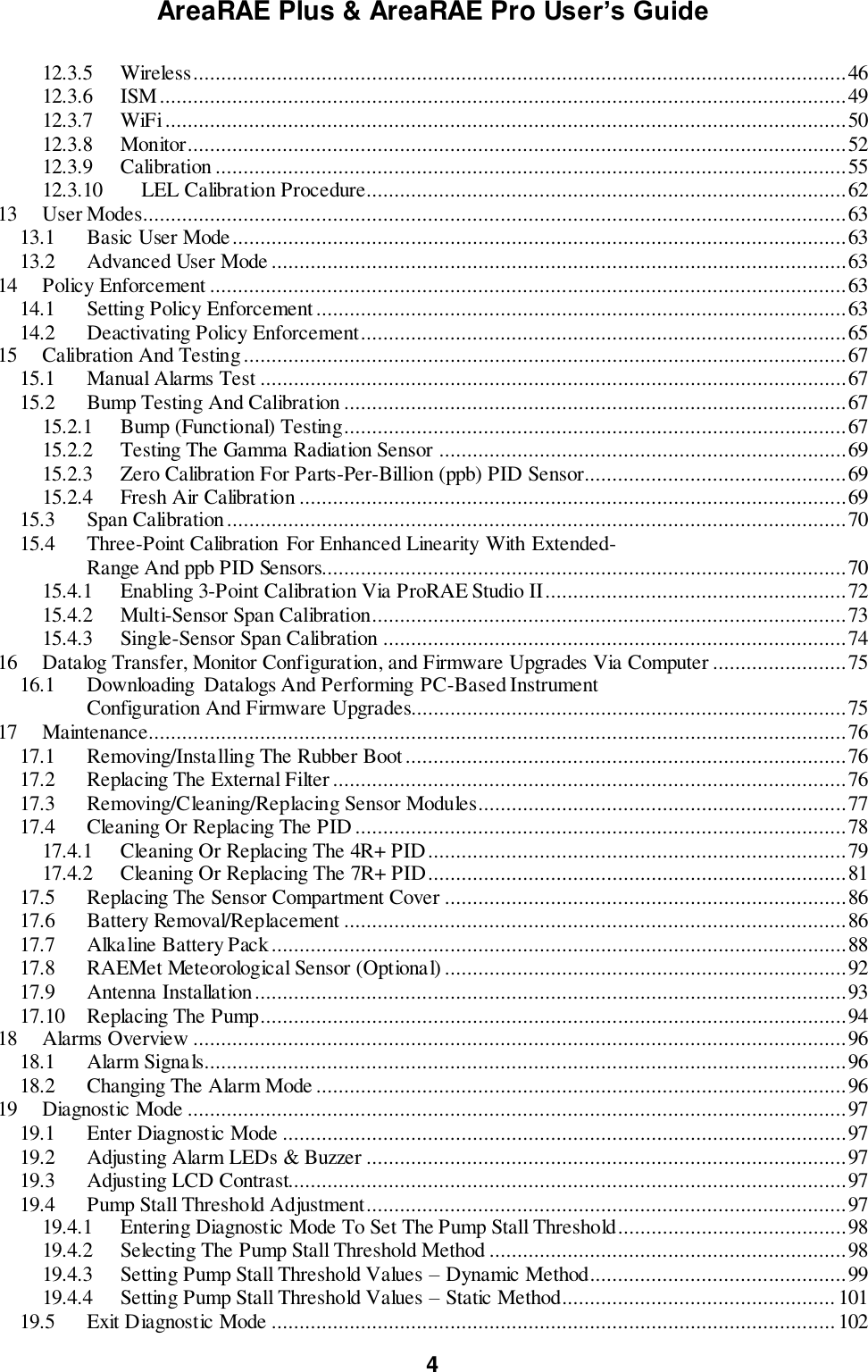
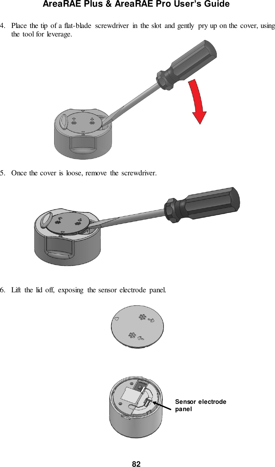
![AreaRAE Plus & AreaRAE Pro User’s Guide 15 3.1 Key Features Up to seven gas sensors (PID, LEL, Toxics) Dedicated radiation sensor slot – Gamma sensor RAEMet station for wind speed and direction, ambient temperature, and relative humidity Multiple onboard wireless options: Primary radio: ISM (900/2400 MHz)/WiFi Secondary radio: Mesh CID2 certified for U.S., Zone 2 ATEX Standard GPS module Relay outputs On the field interchangeable gas sensor (4R+ Smart sensor) Colored rubber boots Battery alkaline adapter External battery charger 108dB alarm buzzer Wraparound LED alarm Easy serviceability (access to pump/ gas sensors/ battery) Large Screen and intuitive User interface using icon and text (translated) [N/-] key [MODE] key Antenna Display Alarm LEDs Alarm buzzer (on side) RAEMet Meteorological Sensor (optional) Alarm LEDs Alarm LED [Y/+] key External filter And gas inlet Charging and USB ports (on side) Alarm buzzer (on side)](https://usermanual.wiki/RAE-Systems/6560A/User-Guide-3055882-Page-15.png)
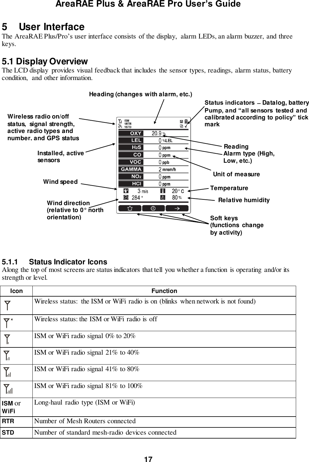
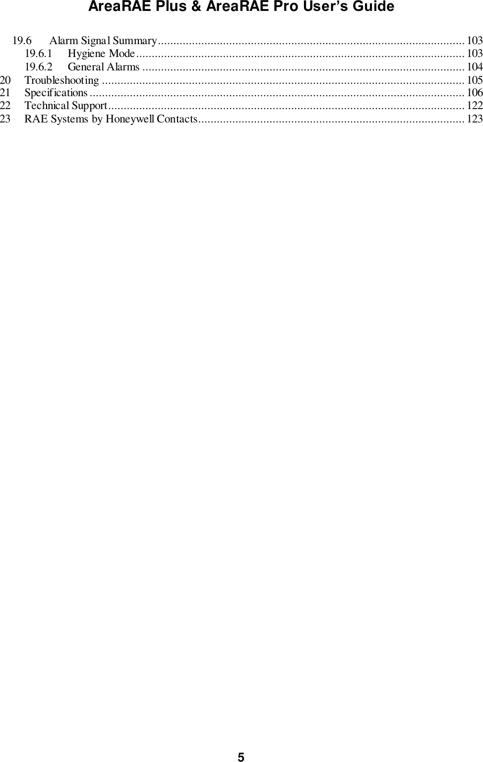
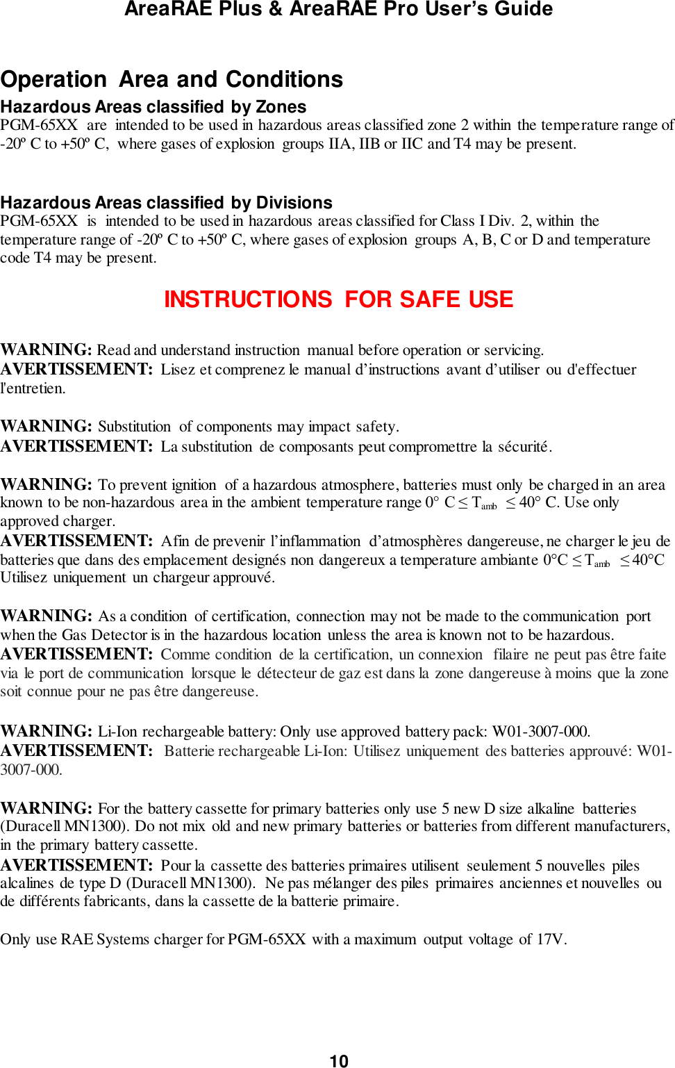
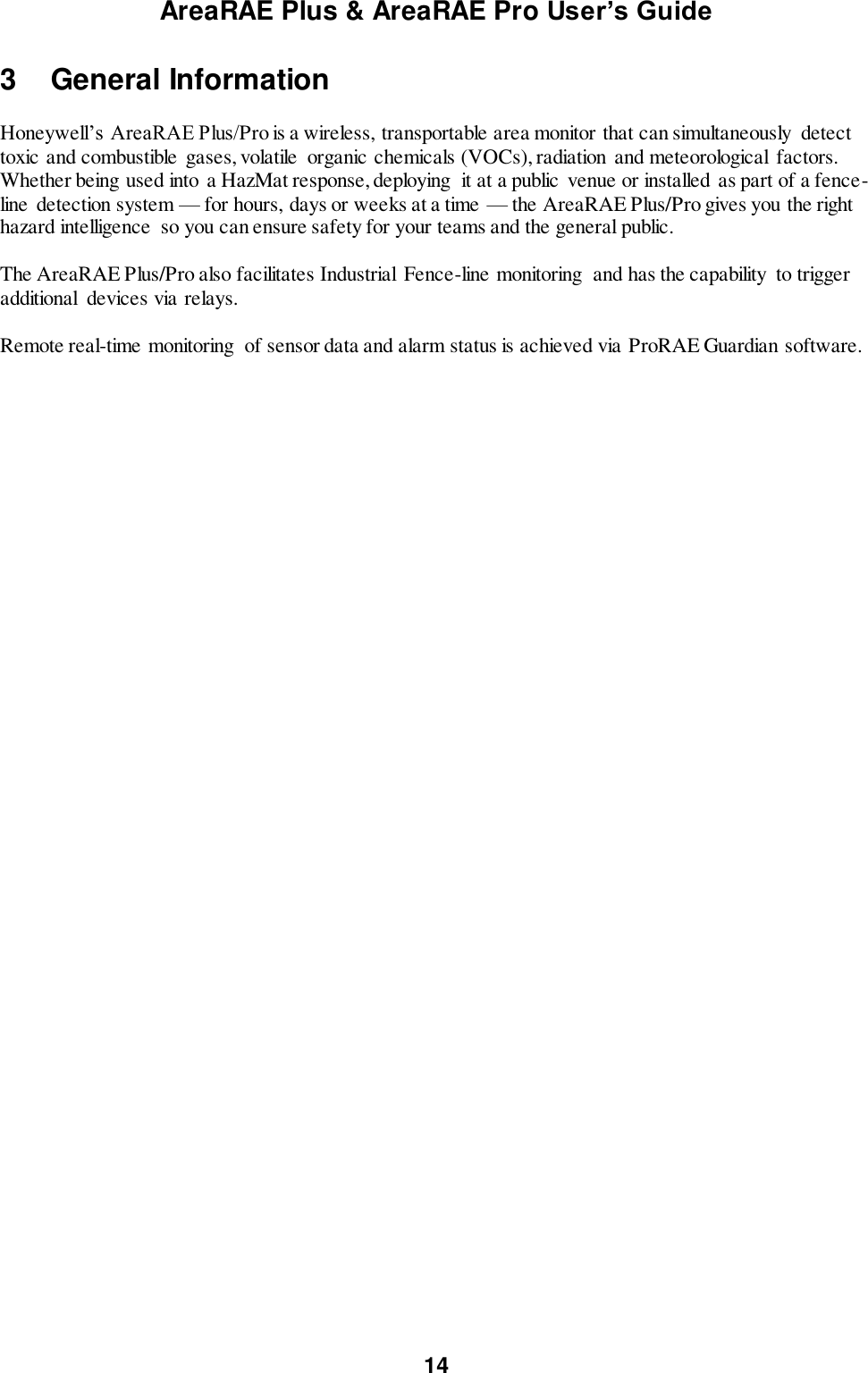
![AreaRAE Plus & AreaRAE Pro User’s Guide 20 5.2 Keys And Interface The AreaRAE Plus/Pro has three keys: Y/+ MODE N/- In addition to their labeled functions, [Y/+], [MODE], and [N/-] act as “soft keys” that control different parameters and make different selections within the instrument’s menus. From menu to menu, each key controls a different parameter or makes a different selection. Three panes along the bottom of the display are “mapped” to the keys. These change as menus change, but at all times the left pane corresponds to the [Y/+] key, the center pane corresponds to the [MODE] key, and the right pane corresponds to the [N/-] key. Here are examples that show the relationships of the keys and functions: In addition to the functions described above, any of the keys can be used to manually activate display backlighting. Press any key when the backlighting is off to turn it on. A subsequent key press is required to carry out an actual function corresponding to that key. 5.2.1 Reverse Direction Sometimes you want to go back to a previous screen rather than advance through an entire set of screens before “wrapping around” to that screen again. To reverse direction: 1. Press and hold [N/-] for 3 seconds. 2. When the arrow changes from pointing to the right to pointing to the left, release your finger. Now when you press [N/-], you step back through the screens. To change direction again: Press and hold [N/-] for 3 seconds and then release. Note: Changing direction does not work with all screens. It works primarily in submenus.](https://usermanual.wiki/RAE-Systems/6560A/User-Guide-3055882-Page-20.png)
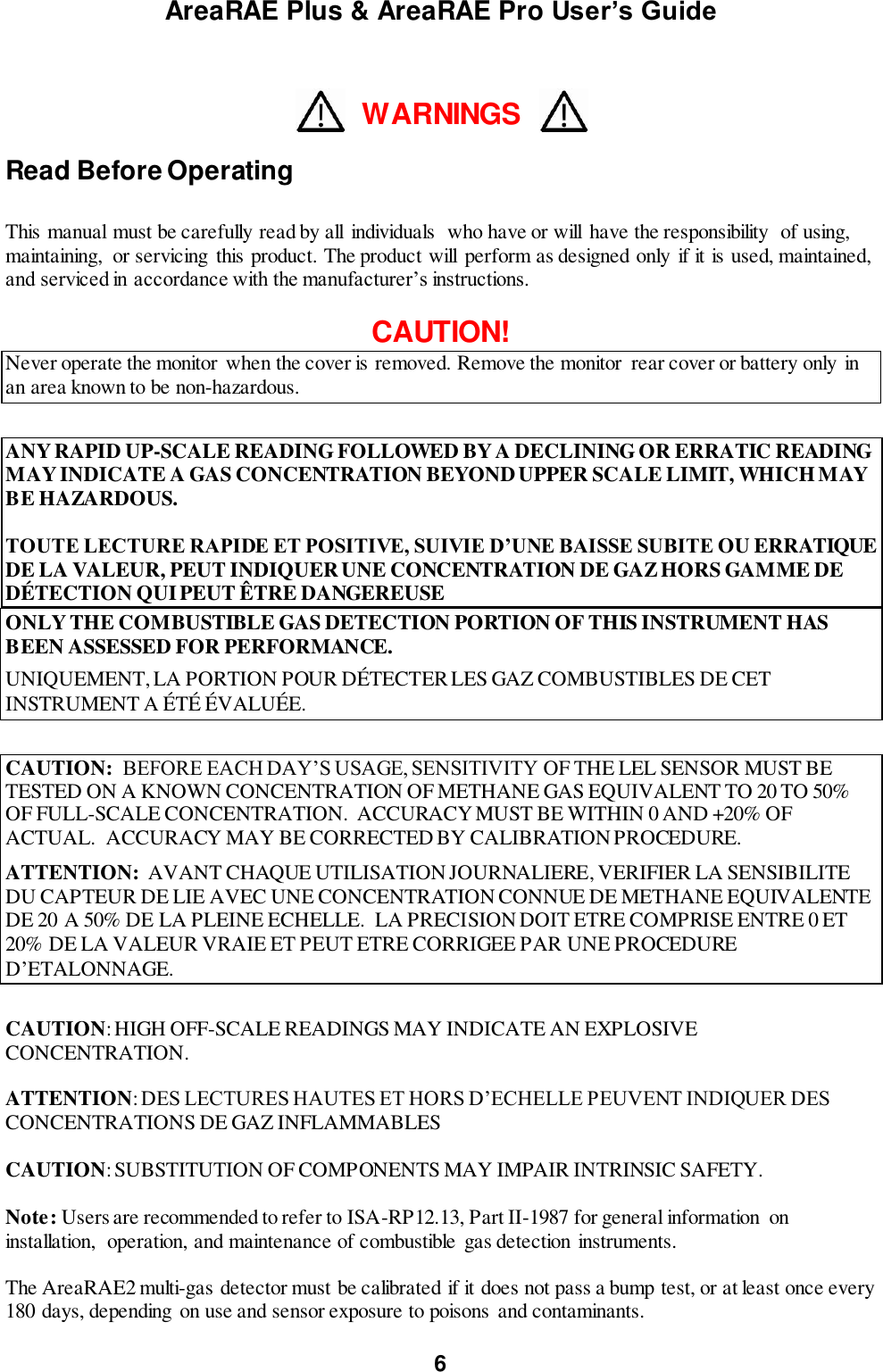
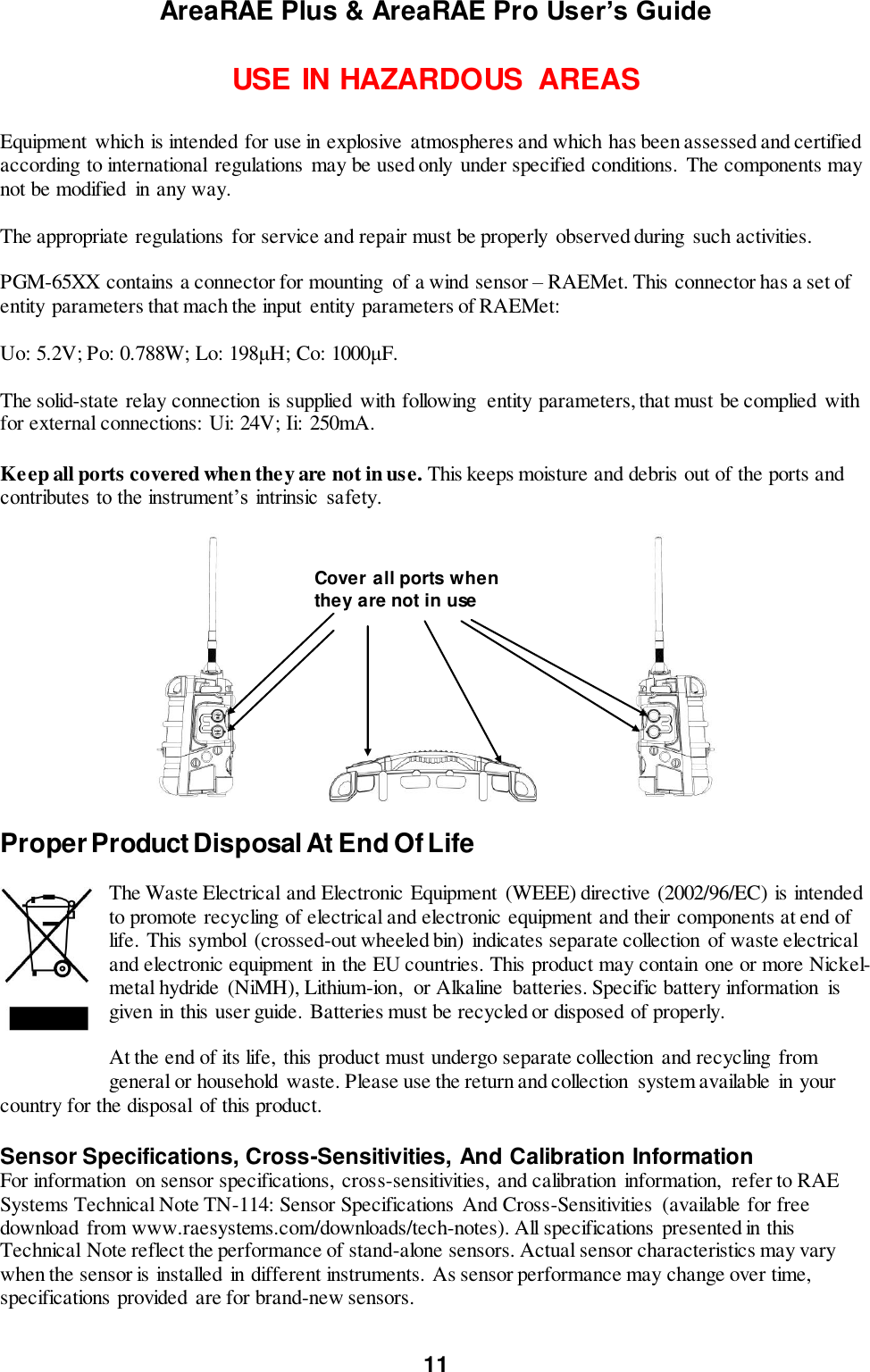
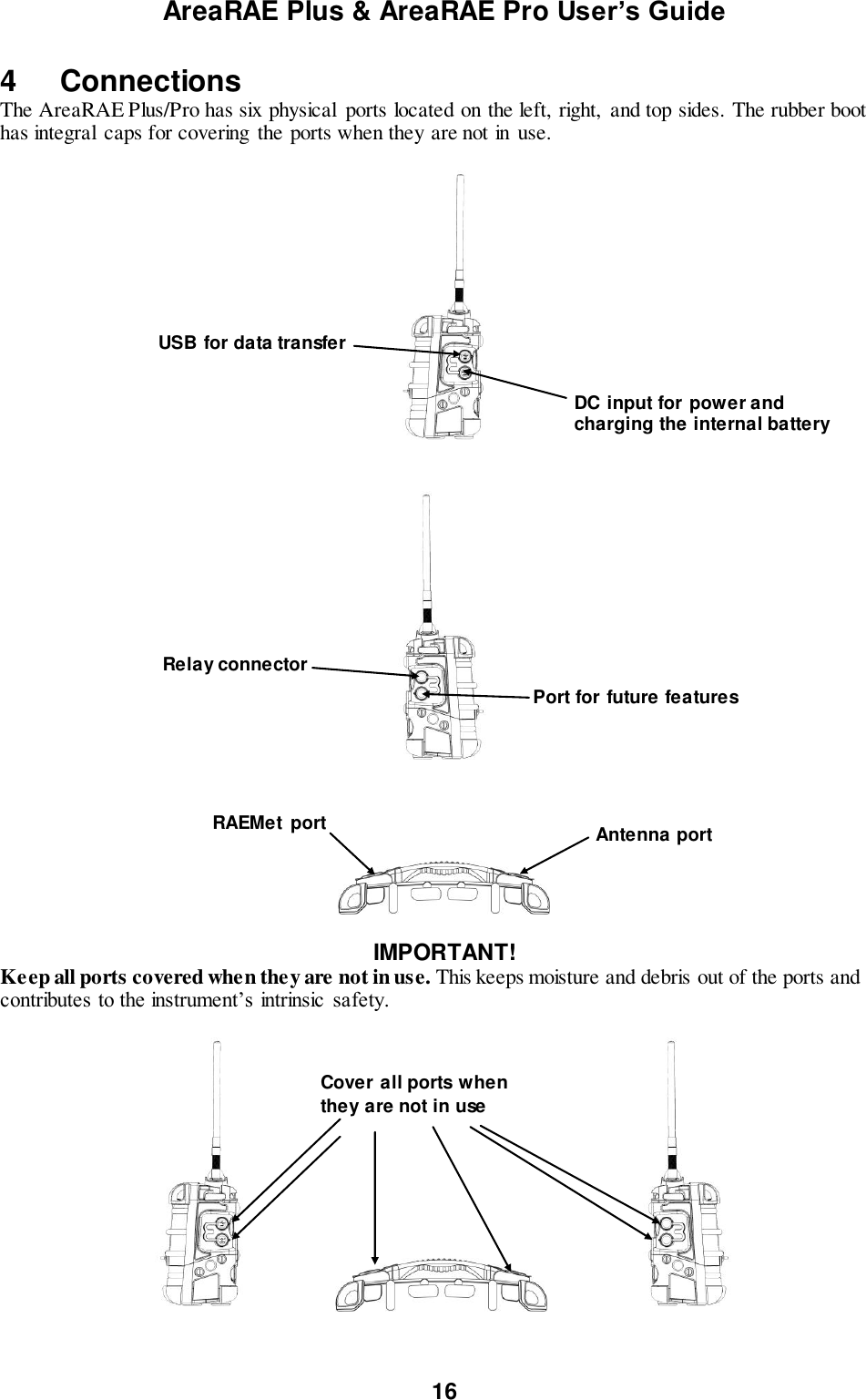
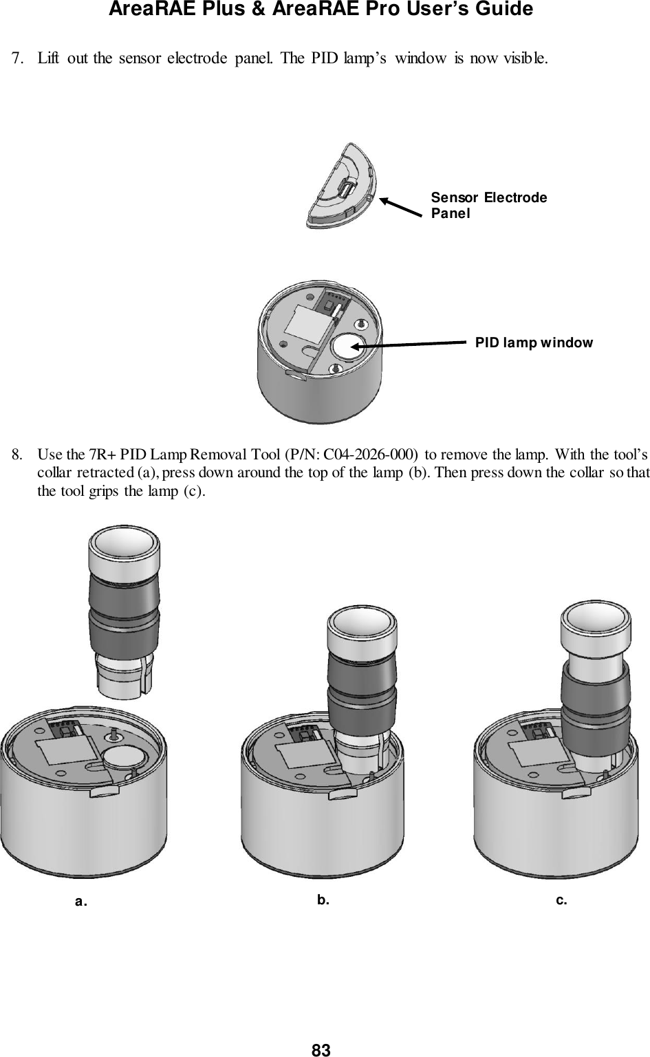
![AreaRAE Plus & AreaRAE Pro User’s Guide 21 5.3 Screen Display For Various Numbers Of Active Sensors The AreaRAE Plus/Pro can display readings from one to eight sensors (including dual sensors), plus four meterology sensors (wind speed, wind direction, temperature, relative humidity) depending on the AreaRAE Plus/Pro’s configuration. In order to maximize readability and the amount of information shown, the display is automatically reconfigured, according to the number and types of sensors in the AreaRAE Plus/Pro. 8 Sensors with meteorology sensors 8 sensors without meteorology sensors 5.4 Glance Mode Glance Mode allows you to get vital information without turning on the AreaRAE Plus/Pro. You can check information such as the instrument’s model and serial number, installed sensor types, wireless modules installed, etc., which may help when taking inventory of instruments and their sensors or when working with service or support personnel. Glance Mode can be enabled/disabled via ProRAE Studio II. 5.4.1 Enter Glance Mode Note: The instrument must be configured so that Glance Mode is turned on (the default mode is “Off”). This can be done in ProRAE Studio II. With the AreaRAE Plus/Pro turned off, press and hold [Y/+] to enter Glance Mode. The feature is latched, meaning that it runs even after you release the [Y/+] key. If you see the message “GLANCE DISABLED,” you must configure the instrument to use Glance Mode. If Glance Mode is enabled, the first screen is displayed. After releasing [Y/+], other screens can be displayed by pressing the [N/-] Key. In ProRAE Studio II, Glance Mode can be enabled or disabled by checking or unchecking the box labeled “Enable Glance Mode.” 5.4.2 Screens Every screen displayed in sequence as configuration. Press [N/-] to advance to the next screen. Press [MODE] to exit Glance Mode. The screens are shown in sequence. 5.4.3 Exit Glance Mode The AreaRAE Plus/Pro exits Glance Mode and turns off when you press the [MODE] key. In addition, if you do not press either key in 60 seconds, the AreaRAE Plus/Pro automatically exits Glance Mode.](https://usermanual.wiki/RAE-Systems/6560A/User-Guide-3055882-Page-21.png)
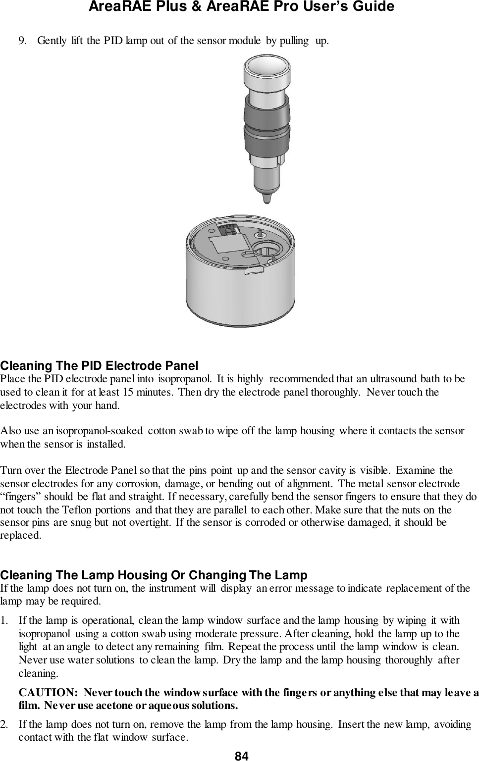
![AreaRAE Plus & AreaRAE Pro User’s Guide 22 5.5 Menus The reading menus are easy to step through by pressing the [N/-] key. Notes: If the instrument is not equipped with a VOC sensor (PID), or is not equipped with an LEL sensor, then screens for those sensors (VOC Gas Status and LEL Gas Status, respectively) are not shown. If ISM or WiFi is not the primary modem, its menu is not displayed. 5.5.1 Operation Mode Navigation Note: Dashed line indicates automatic progression.](https://usermanual.wiki/RAE-Systems/6560A/User-Guide-3055882-Page-22.png)
![AreaRAE Plus & AreaRAE Pro User’s Guide 26 8 WiFi Settings AreaRAE Plus/Pro’s WiFi is designed to operate on a wireless network anchored by ProRAE Guardian monitoring software and using WiFi access points. Operational distance between the instrument and the access point (wireless router) varies, depending on distance, interference, and obstacles. It uses the 802.11b protocol using the 2.4GHz ISM (license-free) frequency band. Note: To ensure the best communication, it is recommended that the WiFi-equipped instruments and access point not be located close to microwave ovens, cordless telephones, or Bluetooth devices. 8.1 Setting WiFi Communication Parameters In ProRAE Studio II WiFi-equipped instruments’ parameters for communication must be set in ProRAE Studio II. 1. Connect WiFi-equipped instrument via USB to a PC running ProRAE Studio II. 2. Place the AreaRAE Plus/Pro in Communications Mode. 3. From the main screen, press [N/-] until you see “Enter Communications Mode?” 4. Press [Y/+]. 5. Select PC. The message on the display should say “Ready To Communicate With Computer”. 1. Start ProRAE Studio II. 2. Log in using your Administrator’s password. 3. Click the “Detect Instruments Automatically” icon. 4. When your WiFi-equipped instrument is detected, click on its information and then click “Select”.](https://usermanual.wiki/RAE-Systems/6560A/User-Guide-3055882-Page-26.png)
![AreaRAE Plus & AreaRAE Pro User’s Guide 33 11 Turning The AreaRAE Plus/Pro On And Off 11.1 Turning The AreaRAE Plus/Pro On With the instrument turned off, press and hold the [MODE] key until the beep sounds and the display and LED alarm lights turn on. Then release the [MODE] key. A RAE Systems logo (or a company name) should appear first. This is followed by a progression of screens that tell you the AreaRAE Plus/Pro’s current settings. 11.1.1 Pausing To View Screens During Startup Press the [MODE] button anytime during the startup sequence to pause the progression. This allows you to view the information for as long as you like. To resume the progression, press [MODE] again. Even if you pause the progression of screens, the startup process is not interrupted. Note: To speed up the startup time, the number of screens shown on startup can be reduced by enabling the Fast Startup option under Programming/Monitor. Then the AreaRAE Plus/Pro’s main reading screen appears. It displays instantaneous readings similar to the following screen (depending on the sensors installed) and is ready for use. Note: If the battery is completely empty, then the display briefly shows the message “Battery Low,” and the AreaRAE Plus/Pro shuts off. You should charge the battery or replace it with a fully charged battery before turning it on again. 11.2 Turning The AreaRAE Plus/Pro Off Press and hold [MODE]. A 5-second countdown to shutoff begins. You must hold your finger on the key for the entire shutoff process until the AreaRAE Plus/Pro is powered off.](https://usermanual.wiki/RAE-Systems/6560A/User-Guide-3055882-Page-33.png)
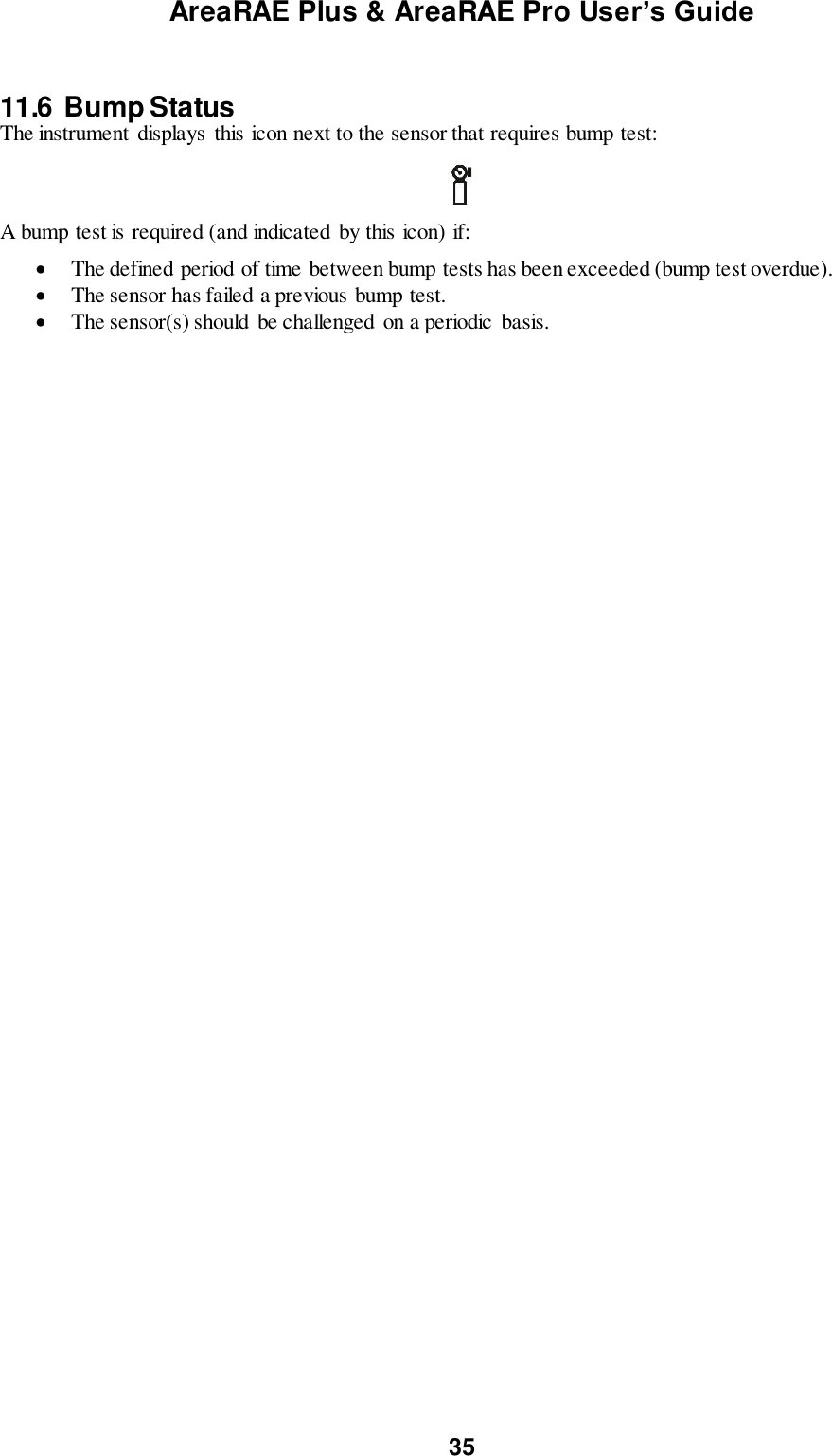
![AreaRAE Plus & AreaRAE Pro User’s Guide 34 11.3 Testing Alarm Indicators Under normal-operation mode and non-alarm conditions, the buzzer, LEDs, and backlight can be tested at any time by pressing [Y/+] once. IMPORTANT! If any of the alarms does not respond to this test, check the Alarm Settings in Programming Mode. It is possible that any or all of the alarms have been turned off. If all of the alarms are turned on, but one or more of them (buzzer or LED lights) does not respond to this test, do not use the instrument. Contact your RAE Systems distributor for technical support. 11.4 Pump Status IMPORTANT! During operation, make sure the probe inlet and the gas outlet are free of obstructions. Obstructions can cause premature wear on the pump, false readings, or pump stalling. During normal operation, the pump icon alternately shows inflow and outflow as shown here: If there is a pump failure or obstruction that disrupts the pump, the alarm sounds and you see this icon blinking on and off: Once the obstruction is removed, you can try to restart the pump by pressing the [Y/+]. If the pump does not restart, and the pump stall alarm continues, consult the Troubleshooting section of this guide or contact RAE Systems Technical Support. It is advisable to perform a pump stall test periodically, to make sure the pump is working properly and there are no leaks in the system. To perform a pump stall test, simply block the gas inlet with your finger. To pass the test, the instrument should go into a pump alarm. Press [Y/+] to disable the alarm and return to normal operation. Note: For all AreaRAE Plus/Pro instruments with a 4R+ PID, if the pump is in alarm for more than five minutes, the PID lamp automatically turns off. The display reading shows “- - -” and there is a “Lamp” alarm. Click [Y/+] to restart the pump. If there is no longer a pump alarm, then the PID lamp will require a 2-minute warm-up to stabilize. During this time, the PID’s reading shows “- - -”. Once the PID lamp is warmed up, the display shows the actual value. 11.5 Calibration Status The instrument displays this icon next to the sensor that requires calibration: Calibration is required (and indicated by this icon) if: The lamp type has been changed. The sensor module has been replaced with one whose calibration is overdue. The defined period of time between calibrations has been exceeded. If you have changed the calibration gas type without recalibrating the instrument. The sensor has failed a previous calibration.](https://usermanual.wiki/RAE-Systems/6560A/User-Guide-3055882-Page-34.png)
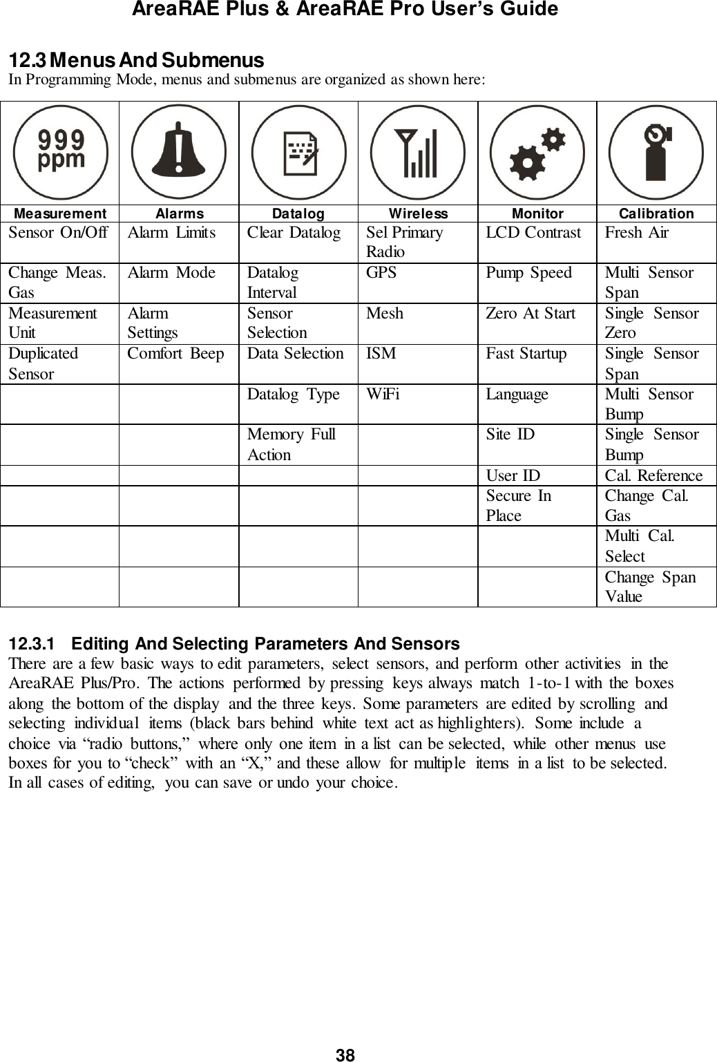
![AreaRAE Plus & AreaRAE Pro User’s Guide 36 12 Programming The menu in Programming Mode is to adjust settings, and calibrate sensors. It has the following submenus: Measurement Alarms Datalog Wireless Monitor Calibration 12.1 Enter Programming In Basic Mode Programming in Basic Mode is limited to calibration only. A password is required to access other programming menus. 1. To enter Programming Mode, press and hold [MODE] and [N/-] until you see the Password screen. 2. Input the 4-digit password: Increase the number from 0 through 9 by pressing [Y/+]. Step from digit to digit using [N/-]. Press [MODE] when you are done. If you make a mistake, you can cycle through the digits by pressing [N/-] and then using [Y/+] to change the number in each position. Note: The default password is 0000. Note: The password screen appears when you enter the Programming Mode the first time after turning the instrument on in Basic Mode, and each time after that.](https://usermanual.wiki/RAE-Systems/6560A/User-Guide-3055882-Page-36.png)
![AreaRAE Plus & AreaRAE Pro User’s Guide 37 Once you enter Programming Mode, the Calibration menu is highlighted. You cannot access other menu items, and you can only perform the following types of calibration: Fresh Air Multi Sensor Span Single Sensor Zero Single Sensor Span The following require password access in Basic Mode or can be directly accessed in Advanced Mode. Multi Sensor Bump Single Sensor Bump Cal. Reference Change Cal. Gas Multi Cal Select Change Span Value To enter a menu and view or edit parameters in its submenus, press [Y/+]. 12.2 Enter Programming In Advanced Mode 1. To enter Programming Mode, press and hold [MODE] and [N/-] until you see the Calibration screen. No password is necessary in Advanced Mode. 2. Press [N/-] to step through the programming screens. Note: Holding down [N/-] advances quickly through the menu options. When a menu item is selected, its name is shown at the top of the screen, and its icon is enlarged. To enter a menu and view or edit parameters in its submenus, press [Y/+].](https://usermanual.wiki/RAE-Systems/6560A/User-Guide-3055882-Page-37.png)
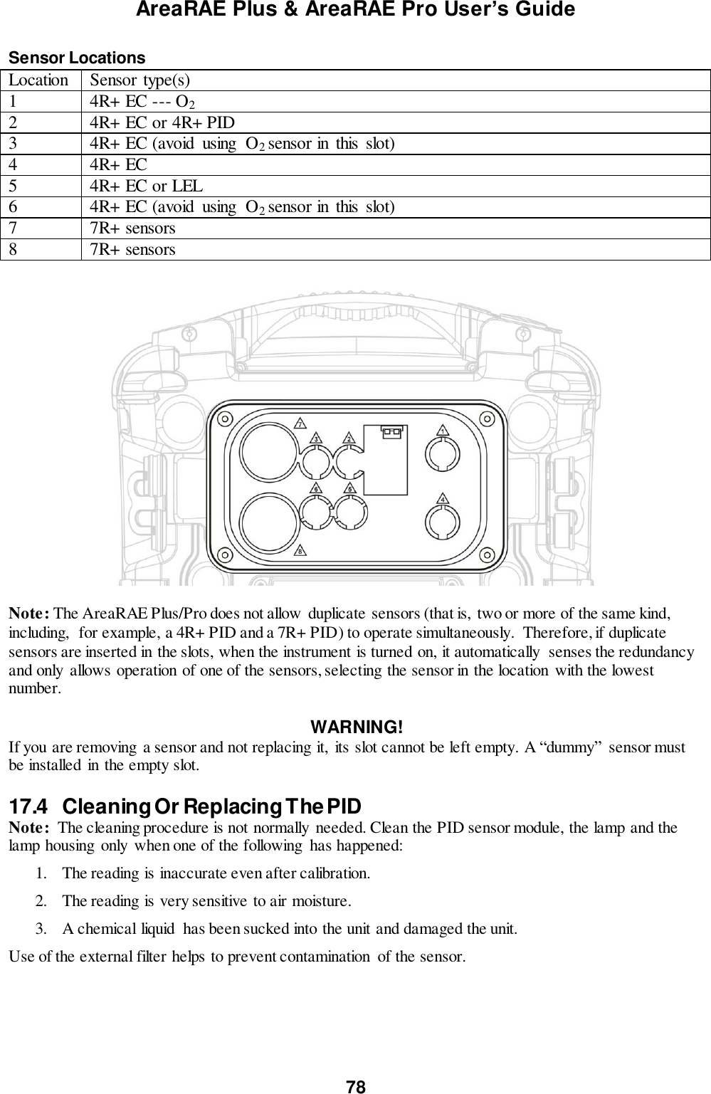
![AreaRAE Plus & AreaRAE Pro User’s Guide 39 12.3.2 Measurement The submenus for Measurement include Sensor On/Off, Change Measurement Gas, and VOC and Gamma (if equipped) Measurement Units. Sensor On/Off You can turn sensors on or off via this submenu. An “X” in a box to the left of a sensor’s name indicates it is turned on. 1. Scroll down the list of sensors using the [N/-] key. 2. Add or remove that gas from the list by pressing [Y/+]. An “X” in a box to the left of a sensor’s name indicates it is selected. 3. Once you have made all your selections, press [MODE] for “Done.”](https://usermanual.wiki/RAE-Systems/6560A/User-Guide-3055882-Page-39.png)
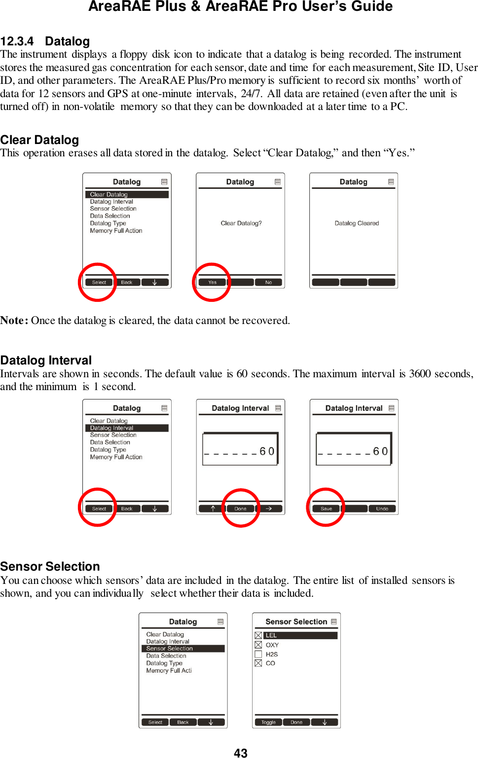
![AreaRAE Plus & AreaRAE Pro User’s Guide 44 Note: Turning a sensor off in the list does not change or erase its settings. Data Selection Data Selection allows you to select which types of data are stored and made available when you download your datalog to a computer via ProRAE Studio II (version 1.04 or higher) software. You can choose any or all of four types of data (you must choose at least one): Minimum Average Maximum Real-Time Datalog Type The instrument offers three options for starting the datalogging process: Auto Automatically collects datalog information every time the instrument is sampling until the datalog memory is full. Manual Datalogging occurs only when you manually initiate it (see below for details). Note: You can only choose one datalog type to be active at a time. About Manual Datalogging When the instrument is set to Manual Datalog, you can turn datalogging on and off by repeatedly pressing [N/-] and stepping through the screens from the main display until you reach the screen that says “Start Datalog?” When you reach the screen that says “Start Datalog?” press [Y/+] to start it. You see “Datalog Started,” confirming that datalogging is now on. You can turn it off by pressing [Y/+] again. If datalogging is running, you can leave it running. However, if you want to turn it off, follow this procedure:](https://usermanual.wiki/RAE-Systems/6560A/User-Guide-3055882-Page-44.png)
![AreaRAE Plus & AreaRAE Pro User’s Guide 45 Press [N/-] repeatedly to step through the screens until you reach the screen that says, “Stop Datalog?” Press [Y/+] to stop datalogging. The screen displays “Datalog Stopped” for a few seconds, before displaying “Start Datalog?” and the datalog interval. You can restart it anytime by pressing [Y/+] from that screen. Memory Full Action When the internal datalog memory is full, the AreaRAE Plus/Pro can either stop collecting data (Stop When Full) or go back to the beginning and overwrite the data from the first entry, second entry, etc. (Wraparound).](https://usermanual.wiki/RAE-Systems/6560A/User-Guide-3055882-Page-45.png)
![AreaRAE Plus & AreaRAE Pro User’s Guide 46 12.3.5 Wireless When an AreaRAE Plus/Pro is equipped with a wireless modem, its settings are controlled via the menu items under “Wireless.” Note: Instruments equipped with WiFi provide different menu choices. Refer to page 26 for details. Select Primary Radio Select the primary radio. 1. Choose between “ISM” and “WiFi” by pressing [N/-]. 2. Select the highlighted state by pressing [Y/+]. 3. Save or register the change: Press [Y/+] to save the change. Press [N/-] to undo the change. Note: Either ISM or WiFi can be active, but not both at the same time. GPS GPS receivers operate by line of sight with global positioning satellites. A receiver must be able to get signals from at least four satellites in order to calculate longitude and latitude (there are currently 30 GPS satellites orbiting the earth). The more satellites a GPS receiver can “see,” the more accurate and reliable the positioning. For a GPS-equipped AreaRAE Plus/Pro to work properly, it must have a direct line of sight to a satellite, meaning it will not work well (if at all) indoors. Although radio signals from navigation satellites can pass through clouds, glass, plastic and other lightweight materials, satellite navigation receivers do not work underground or in other enclosed spaces. If you need to operate a monitor under a roof or anything else that obstructs a clear view of the sky, you may need to take the AreaRAE Plus/Pro outdoors into a nearby clear area, manually set GPS coordinates in ProRAE Guardian, and allow those coordinates to be used on maps in ProRAE Guardian running on a host computer. You can turn the GPS power on or off. 1. Press [Y/+] to see on and off states, and which is selected. 2. Press [N/-] to scroll to “On” or “Off.” 3. Press [Y/+] to select. 4. Press [Y/+] to “Save.” You can also press [N/-] to undo.](https://usermanual.wiki/RAE-Systems/6560A/User-Guide-3055882-Page-46.png)
![AreaRAE Plus & AreaRAE Pro User’s Guide 47 Mesh The AreaRAE Plus/Pro’s secondary Mesh radio is designed to work in a RAE Systems wireless mesh radio network. This type of flexible, robust wireless network provides reliable, low-cost operation and supports point-to-point and point-to-multi-point networking with ProRAE Guardian monitoring software. Options include: Power On/Off PAN ID Channel Factory Reset On/Off 1. Press [Y/+] to see on or off state, and which is selected. 2. Press [N/-] to scroll to “On” or “Off.” 3. Press [Y/+] to select. 4. Press [Y/+] to “Save.” You can also press [N/-] to undo. PAN ID The AreaRAE Plus/Pro and any other devices that you want to interconnect wirelessly must have the same PAN ID. You can set the PAN ID in the instrument or through ProRAE Studio II. 1. Press [Y/+] to increase the number and [N/-] to advance to the next digit. 2. After moving to the last digit and making changes, press [MODE]. Press [Y/+] to save the change. Press [N/-] to undo the change.](https://usermanual.wiki/RAE-Systems/6560A/User-Guide-3055882-Page-47.png)
![AreaRAE Plus & AreaRAE Pro User’s Guide 48 Channel The AreaRAE Plus/Pro and any other devices that you want to interconnect wirelessly must be operating on the same channel. 1. Press [N/-] to step through the channel numbers from 1 through 10. 2. Once your selection is highlighted: Press [Y/+] to select the channel. Press [Y/+] to save your choice or press [N/-] to undo your changes. Note: You cannot change the channel setting on an instrument equipped with a radio modem that operates at a frequency of 868 MHz. Factory Reset Restore all the wireless settings to their original factory defaults. Caution! Once you reset the wireless settings, you cannot retrieve any of the settings deleted by performing this reset. Press [Y/+] to reset the wireless settings. Press [N/-] to exit without resetting the wireless settings.](https://usermanual.wiki/RAE-Systems/6560A/User-Guide-3055882-Page-48.png)
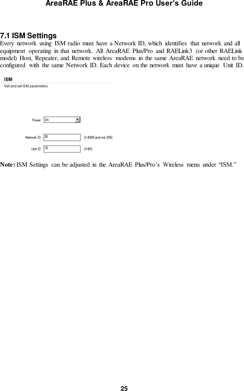
![AreaRAE Plus & AreaRAE Pro User’s Guide 49 12.3.6 ISM The AreaRAE Plus/Pro and any other devices that you want to interconnect wirelessly through ISM must have the same Network ID (1 to 4095, but do not use 255), as well as a unique Unit ID (1 through 64). You can set the Network ID in the instrument or through ProRAE Studio II. 1. Press [Y/+] to increase the number and [N/-] to advance to the next digit. 2. After moving to the last digit and making changes, press [MODE]. Press [Y/+] to save the change. Press [N/-] to undo the change. Power On/Off You can turn the ISM radio’s power on or off. 1. Press [Y/+] to see on or off state, and which is selected. 2. Press [N/-] to scroll to “On” or “Off.” 3. Press [Y/+] to select. 4. Press [Y/+] to “Save.” You can also press [N/-] to undo. Network ID Every ISM network must have a Network ID, which identifies that network and all equipment operating in that network. All instruments, including the host, repeaters, etc., in the same network need to be configured with the same Network ID. 1. Press [Y/+] to increase the number and [N/-] to advance to the next digit. 2. After moving to the last digit and making changes, press [MODE]. Press [Y/+] to save the change. Press [N/-] to undo the change.](https://usermanual.wiki/RAE-Systems/6560A/User-Guide-3055882-Page-49.png)
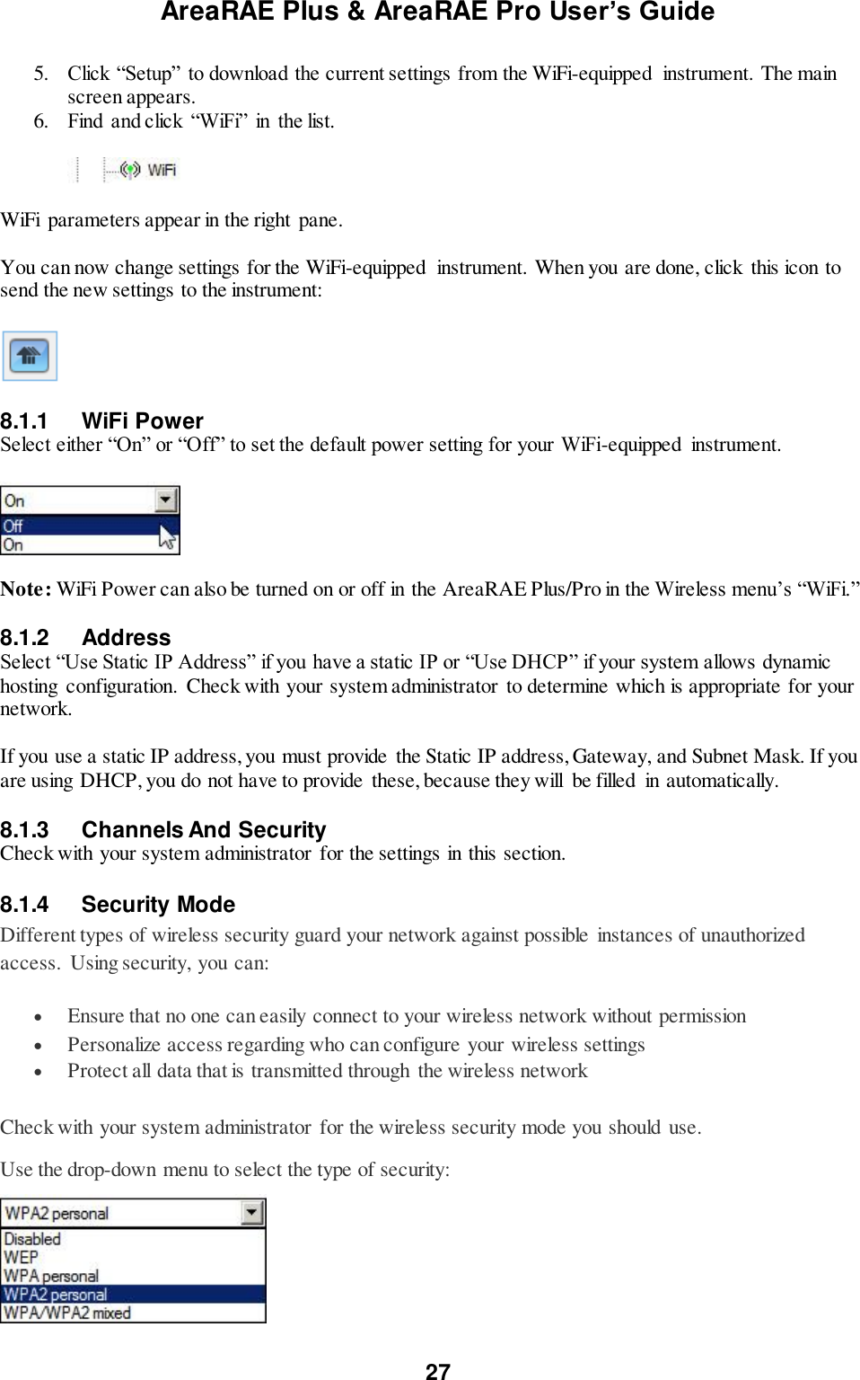
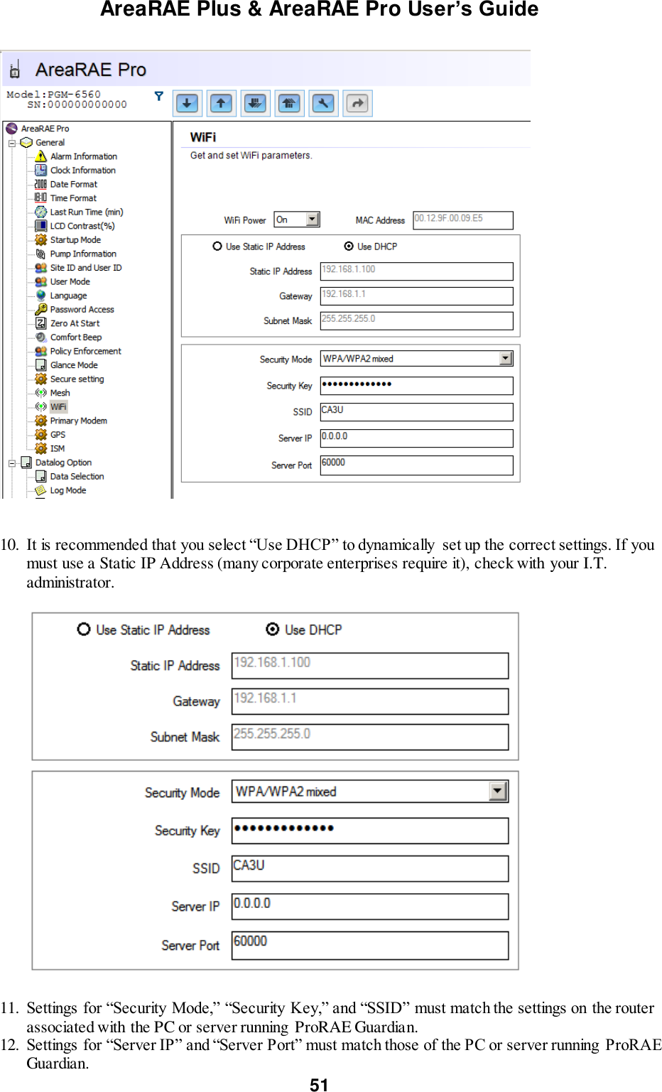
![AreaRAE Plus & AreaRAE Pro User’s Guide 50 Unit ID Each instrument in an ISM network must be assigned a unique Unit ID (between 00 and 99). Make sure that the unit ID is not duplicated among any of the units within the same network. 1. Press [Y/+] to increase the number and [N/-] to advance to the next digit. 2. After moving to the last digit and making changes, press [MODE]. Press [Y/+] to save the change. Press [N/-] to undo the change. 12.3.7 WiFi You can turn the WiFi radio’s power on or off. 1. Press [Y/+] to see on and off states, and which is selected. 2. Press [N/-] to scroll to “On” or “Off.” 3. Press [Y/+] to select. 4. Press [Y/+] to “Save.” You can also press [N/-] to undo. In order to communicate via WiFi, you must configure WiFi settings for the AreaRAE Plus/Pro to match your router by using ProRAE Studio II: 1. Connect a USB cable between the AreaRAE Plus/Pro and a PC running ProRAE Guardian. 2. In Normal mode, press the [N/-] key until the screen shows “Enter Communication Mode?” 3. Press [Y/+]. 4. Start ProRAE Studio II on the PC. 5. Log in as Administrator. You must provide a password (the default is “rae”.) 6. Click the “A” (for Automatic) detection. 7. When the AreaRAE Plus/Pro shows up in the list, click on it and then click “Select.” 8. Click “Setup” when the list of items is shown on the left. This downloads the instrument’s setup. 9. Click “WiFi.” This is where you see the current WiFi parameters and can set new ones.](https://usermanual.wiki/RAE-Systems/6560A/User-Guide-3055882-Page-50.png)
![AreaRAE Plus & AreaRAE Pro User’s Guide 52 13. Once your settings are made, upload the settings to the AreaRAE Plus/Pro. Click this icon: 14. When uploading is finished, quit ProRAE Studio II. 15. On the AreaRAE Plus/Pro, press [Y/+] to exit Communication mode. 16. Disconnect the USB cable. 12.3.8 Monitor The submenus under “Monitor” control the following: LCD Contrast Pump Speed Zero At Start Fast Startup Language Site ID User ID Secure In Place Press [N/-] to advance through the submenus, and when you reach the last one, it returns to the first selection. LCD Contrast The display’s contrast can be increased or decreased from its default setting. You may not need to ever change the default setting, but sometimes you can optimize the display to suit extreme temperature and ambient brightness/darkness conditions. 1. Use the [Y/+] and [N/-] keys to decrease or increase LCD contrast, respectively (the bar graph aids in setting it). 2. When you are done, press [MODE] to select “Done.” If you have not made a change, it exits to the submenu’s next selection. If you have made a change, you are prompted at the next screen to press [Y/+] to save the change or [N/-] to undo the change and exit to the next submenu selection. Pump Speed The AreaRAE Plus/Pro’s pump can operate at two speeds, high and low. It is recommended that you run the pump at high speed. 1. Press [Y/+] to see the current, selected setting. 2. Press [N/-] to scroll to “High” or “Low.”](https://usermanual.wiki/RAE-Systems/6560A/User-Guide-3055882-Page-52.png)
![AreaRAE Plus & AreaRAE Pro User’s Guide 53 3. Press [Y/+] to select. 4. Press [Y/+] to “Save.” You can also press [N/-] to undo. Zero At Start If your AreaRAE Plus/Pro has been configured to perform a zero (fresh air) calibration upon startup, called Zero At Start, then the startup routine is interrupted so that you can perform a fresh air calibration for all sensors prior to using the instrument. 1. Press [Y/+] to see on or off state, and which is selected. 2. Press [N/-] to scroll to “On” or “Off.” 3. Press [Y/+] to select. 4. Press [Y/+] to “Save.” You can also press [N/-] to undo. If you do not want to perform a zero calibration, press [MODE] to bypass it. If you start a zero calibration and want to abort it, press [N/-], and the calibration stops and the main display is shown. Fast Startup Fast Startup reduces the amount of time between when the instrument is turned on and is ready for use. It skips showing you many settings and is best suited to environments where the AreaRAE Plus/Pro is turned on and off very often during a given day. If Fast Startup is not selected, then when the instrument starts, it shows you details of each sensor, including calibration information, high and low alarm settings, etc. 1. Press [Y/+] to see on or off state, and which is selected. 2. Press [N/-] to scroll to “On” or “Off.” 3. Press [Y/+] to select. 4. Press [Y/+] to “Save.” You can also press [N/-] to undo. Language English is the default language, but other languages can also be selected for the instrument. Note: The language can also be changed through ProRAE Studio II. 1. Press [Y/+] to see the current, selected language. 2. Press [N/-] to scroll to the language you want. 3. Press [Y/+] to select. 4. Press [Y/+] to “Save.” You can also press [N/-] to undo. Site ID Choose and enter an 8-digit Site ID to uniquely identify the particular site where the instrument is to be used. The first four digits can be an alphabet letter or number, while the last four digits can only be numbers. This Site ID is included in the datalog report. Note: Advance through the alphabet and numbers (0 through 9) by one with each press of the [Y/+] key. To scroll quickly, hold down the [Y/+] key for as long as you want it to scroll rapidly. User ID Enter an 8-digit alphanumeric User ID to uniquely identify a user. This User ID is included in the datalog report. The first four characters of a customized User ID act as an identifier for montoring the instrument. Note: Advance through the alphabet and numbers (0 through 9) by one with each press of the [Y/+] key. To scroll quickly, hold down the [Y/+] key for as long as you want it to scroll rapidly.](https://usermanual.wiki/RAE-Systems/6560A/User-Guide-3055882-Page-53.png)
![AreaRAE Plus & AreaRAE Pro User’s Guide 54 Secure In Place Secure In Place provides anti-tampering features to prevent unwanted access to screens or functions. These features use passwords to control access. Power Down Lock: Requires that you enter the system password to power down the AreaRAE Plus/Pro. Note: This feature is disabled by default, and is configurable via ProRAE Studio II and via the AreaRAE Plus/Pro’s menu. Screen Lock: AreaRAE Plus/Pro’s Screen Lock mode prevents changing the screen from the main reading display without first entering a password. When Screen Lock is active, only the instantaneous reading screen is displayed. Note: When screen lock is active, the alarm test function is not available by pressing the [Y/+] key, and the alarm test soft key is not displayed. Remote Monitoring Mode: When AreaRAE Plus/Pro is programmed in Remote Monitoring mode, the screen displays the text “Monitor Active,” indicating that the instrument is actively monitoring. During alarm events, the display reverts to Screen Lock mode. Once the alarm conditions are cleared, Remote Monitoring mode resumes. Note: If enabled, Remote Monitoring mode is active upon entry to Normal mode, immediately after startup, and/or upon exiting Programming mode. To select a Secure In Place feature (or to disable all of them): 1. Press [Y/+] to see the currently selected mode. 2. Press [N/-] to scroll to the mode you want. 3. Press [Y/+] to select. 4. Press [Y/+] to “Save.” You can also press [N/-] to undo. Your options are: Power Down Lock Screen Lock Remote Monitoring Mode All Disabled](https://usermanual.wiki/RAE-Systems/6560A/User-Guide-3055882-Page-54.png)
![AreaRAE Plus & AreaRAE Pro User’s Guide 55 12.3.9 Calibration Use this menu to perform a bump test or zero or span calibration for one or more sensors, and change the gas concentration value used in bump tests and span calibration, as well as choose which sensors will be calibrated at the same time. Fresh Air This procedure determines the zero point for all the sensors that require a zero calibration. For the oxygen sensor, Fresh Air calibration sets the point equal to the concentration of oxygen in ambient air (approximately 20.9% volume). Note: Fresh air calibration is performed on all enabled gas sensors at the same time. To perform Fresh Air calibration on multiple sensors: 1. Connect the instrument’s inlet to a source of dry, clean ambient air. 2. At the Calibration Menu, select “Fresh Air.” Press [Y/+] once to enter the fresh air calibration sub-menu. 3. Start the flow of dry zero air, if used. 4. Press [Y/+] to start fresh air calibration. 5. A countdown screen appears. You can abort the calibration at any time during the countdown by pressing [N/-]. 6. If the calibration is not aborted, the display shows the sensor names and tells you whether the fresh air calibration passed or failed, followed by the sensors’ fresh air readings. Multi Sensor Span Depending on the configuration of your AreaRAE Plus/Pro and the span gas you have, you can perform a Span calibration simultaneously on multiple sensors. The selected sensors are shown on the screen, along with the concentration settings for their Span gas. With calibration gas connected to the instrument, start a multi span by applying gas to the instrument. Calibration should start after a few seconds. If not, press [Y/+]. If you do not want to perform a multi span, press [MODE]. Note: You can abort a multi span by pressing [N/-] once testing has started. When the Multi Span is done, a screen is shown, with the sensor names and either “Pass” or “Fail” shown next to them. Note: Dotted line indicates automatic progression.](https://usermanual.wiki/RAE-Systems/6560A/User-Guide-3055882-Page-55.png)
![AreaRAE Plus & AreaRAE Pro User’s Guide 56 Single Sensor Zero This allows you to perform zero (fresh air) calibration on individual sensors. Even though most toxic gas sensors can be zeroed in fresh air, some sensors such as a parts-per-billion PID sensor for volatile organic compounds (VOCs) should not be zeroed in fresh air. VOCs are normally present in ambient air, so zeroing these sensors in ambient air will not allow for a true zero to be set for such sensors. The parts-per-billion PID sensor with should only be zeroed with zero air or in ambient air using a charcoal filter or a VOC zeroing tube. 1. If you are using a charcoal filter, connect it to the instrument. 2. If you are using dry air, connect the instrument to a source of zero air. 3. At the Calibration Menu, select “Single Sensor Zero.” Press [Y/+] once to enter the zero calibration sub-menu. 4. Start the flow of zero air, if used. 5. Press [Y/+] to start zero calibration. 6. A countdown screen appears. You can abort the calibration at any time during the countdown by pressing [N/-]. 7. If the calibration is not aborted, the display shows the sensor names and tells you whether the zero calibration passed or failed, followed by the sensors’ zero calibration readings. Note: Dotted line indicates automatic progression.](https://usermanual.wiki/RAE-Systems/6560A/User-Guide-3055882-Page-56.png)
![AreaRAE Plus & AreaRAE Pro User’s Guide 57 Single Sensor Span Instead of performing a span calibration on multiple sensors simultaneously, you can select a single sensor and perform a span calibration. Note: If a calibration icon (bottle with bottom portion filled in) is shown next to any of the sensors, it means that the sensor is due for a full calibration. To perform span calibration of an individual sensor, follow these steps: 1. At the Calibration Menu, select “Single Sensor Span.” 2. Select a sensor to calibrate from the list. 3. Install the “T” tube and connect it to a source of calibration gas. 4. Verify that the displayed calibration value meets the concentration specified on the gas cylinder. 5. Start the flow of calibration gas. 6. Press [Y/+] to start calibrating or wait for calibration to start automatically. 7. A countdown screen appears. You can abort the calibration at any time during the countdown by pressing [N/-]. Note: Dotted line indicates automatic progression.](https://usermanual.wiki/RAE-Systems/6560A/User-Guide-3055882-Page-57.png)
![AreaRAE Plus & AreaRAE Pro User’s Guide 58 8. If the calibration is not aborted, the display shows the sensor names and tells you whether the calibration passed or failed, followed by the sensor readings. Note: The gamma radiation sensor comes pre-calibrated from the factory and does not require routine calibration. However, you can check it by placing a check-source on the rear of the AreaRAE Plus/Pro equipped with a gamma sensor to check the readings. Place the check-source near the upper middle of the rear of the instrument and hold it until you see the Gamma reading change in the display. Multi Sensor Bump Depending on the configuration of your AreaRAE Plus/Pro and the span gas you have, you can perform a bump test simultaneously on multiple sensors. The selected sensors are shown on the screen. With calibration gas connected to the instrument, start a multiple bump test by applying gas to the instrument and pressing [Y/+]. If you do not want to perform a multiple bump test, press [MODE]. Note: You can abort a multiple bump test by pressing [N/-] once testing has started. When the Multi Bump test is done, a screen is shown, with the sensor names and either “Pass” or “Fail” shown next to them.](https://usermanual.wiki/RAE-Systems/6560A/User-Guide-3055882-Page-58.png)
![AreaRAE Plus & AreaRAE Pro User’s Guide 59 Single Sensor Bump This menu allows a bump test to be performed on an individual sensor of your choice. Note: If a bump test icon (bottle with bottom portion not filled in) is shown next to any of the sensors, it means that the sensor is due for a bump test. To perform a bump test on an individual sensor, follow these steps: 1. At the Calibration Menu, select “Single Sensor Bump.” 2. Scroll down the list using [N/-], and then press [Y/+] to select a sensor to bump test. 3. Install the “T” tube and connect it to a source of calibration gas. 4. Verify that the displayed calibration value meets the concentration specified on the gas cylinder. 5. Start the flow of calibration gas. 6. Press [Y/+] to start calibrating or wait for the bump test to start automatically. 7. A countdown screen appears. You can abort the bump test at any time during the countdown by pressing [N/-]. 8. If the bump test is not aborted, the display shows the sensor names and tells you whether the bump test passed or failed, followed by the sensor readings. Important! After each sensor is bump tested, and you press “OK,” the next sensor in the menu list is highlighted. Note: Dotted line indicates automatic progression.](https://usermanual.wiki/RAE-Systems/6560A/User-Guide-3055882-Page-59.png)
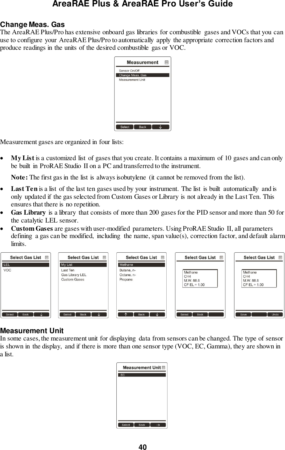
![AreaRAE Plus & AreaRAE Pro User’s Guide 60 Cal. Reference It is sometimes desirable to calibrate a sensor (PID for VOC, and LEL) with a specific gas for best response to a gas you are surveying. The Cal. Reference library contains a list of reference gases that can be selected for the PID and LEL sensors. Choose the sensor, and then select from the list of reference gases. Change Cal. Gas You can change the calibration gas for the AreaRAE Plus/Pro’s PID and LEL sensors. Select from a custom list that you create (My List), the last ten gases used, the built-in gas library for your PID lamp, and user-defined custom gases. Each gas is shown in the list for selection and the screen automatically changes to show its full name, chemical formula, molecular weight (M.W.) and correction factor (CF). Multi Cal. Select This menu allows you to define a group of sensors to be bump tested and span calibrated together. Simultaneous testing and calibration of multiple sensors shortens the bump test and calibration processes and reduces the number of individual gas cylinders you need. For example, it may be more efficient to use a single cylinder with a four-gas mix including 50% LEL Methane, 18% O2, 10 ppm H2S, and 50 ppm CO, to calibrate the LEL, O2, CO, and H2S sensors at one time, compared to using four distinct gas cylinders and calibrate these sensors individually in sequence. In order for sensors to be calibrated together, all of them must be selected using Multi Cal. Select. 1. Scroll down the list of sensors using the [N/-] key. 2. Add or remove that gas from the list by pressing [Y/+]. An “X” in a box to the left of a sensor’s name indicates it is selected. 3. Once you have made all your selections, press [MODE] for “Done.”](https://usermanual.wiki/RAE-Systems/6560A/User-Guide-3055882-Page-60.png)
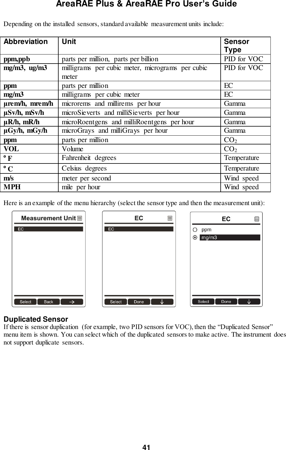
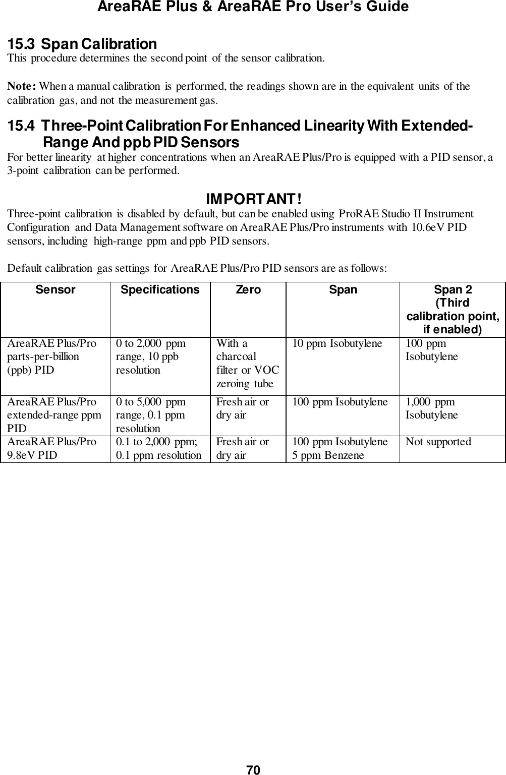
![AreaRAE Plus & AreaRAE Pro User’s Guide 61 Change Span Value You can individually set the span gas concentration for each sensor. This concentration setting will also be used for a bump test. The units of measure (ppm, %LEL, etc.) are shown on the display. 1. Scroll down the list of sensors using the [N/-] key. 2. Press [Y/+] to select it. 3. Press [N/-] to step through the digits. 4. Press [Y/+] to increase the number from 0 through 9. Once the number 9 is reached, pressing [Y/+] causes the numbers to “wrap around” to 0 and count up again. 5. Once you have set the desired value, press [MODE] for “Done.” This registers the new span value. Change Span 2 Value For enhanced accuracy, it is possible to perform a second Span calibration in addition to Zero and Span calibrations. Your instrument first must be set to allow this third calibration. This requires using ProRAE Studio II software and a PC, as well as a higher concentration of calibration gas. Note: 3-point calibration is the default for AreaRAE Pro for ppb resolution or the high range (0 to 5,000 ppm); for other configurations, 2-point calibration is the default. Note: You can only disable 3-point calibration capability by using ProRAE Studio II again. 1. Press [Y/+] to select VOC. 2. Press [N/-] to step through the digits. 3. Press [Y/+] to increase the number from 0 through 9. Once the number 9 is reached, pressing [Y/+] causes the numbers to “wrap around” to 0 and count up again. 4. Once you have set the desired value, press [MODE] for “Done.” This registers the new second span value. 5. Press [Y/+] for “Save” and [N/-] for “Undo.”](https://usermanual.wiki/RAE-Systems/6560A/User-Guide-3055882-Page-61.png)
![AreaRAE Plus & AreaRAE Pro User’s Guide 62 12.3.10 LEL Calibration Procedure You must perform a separate zero calibration for the LEL sensor and then perform a span calibration. Important! Before calibrating, make sure pump is on its high setting. This is in the “Pump Speed” submenu under the “Monitor” menu item. To calibrate the LEL sensor, follow these two procedures: Zero Sensor Calibration For The LEL Sensor 1. Turn on the AreaRAE Plus/Pro and allow it to warm up for 20 minutes in ambient air. 2. In Programming mode, Select “Calibration” and then select “Single Sensor Zero.” 3. Select “LEL.” 4. Calibrate the LEL sensor’s zero point with ambient air. 5. After zero calibration is complete, press [MODE] to return to the Calibration menu. “Single Sensor Span” is highlighted Span Calibration For The LEL Sensor 1. Press [Y/+] to select “Single Sensor Span.” 2. Press [N/-] until “LEL Sensor” is highlighted. 3. Press [Y/+] to select “LEL Sensor.” 4. Screw one end of a “T” using Teflon tubing to the AreaRAE Plus/Pro filter on the inlet. (You can use RAE Systems P/N: W01-3003-000). 5. Attach the other end to the flow regulator of a calibration cylinder with 50% LEL methane (unless otherwise specified ). The flow rate should not be less than 750cc/min. 6. Start the flow of calibration gas. 7. Press [Y/+] to start calibration. 8. When calibration is complete, shut off the calibration gas flow and disconnect the calibration tubing. 9. Press [MODE] to exit to the menu. (You may perform other calibrations. Otherwise, exit.)](https://usermanual.wiki/RAE-Systems/6560A/User-Guide-3055882-Page-62.png)
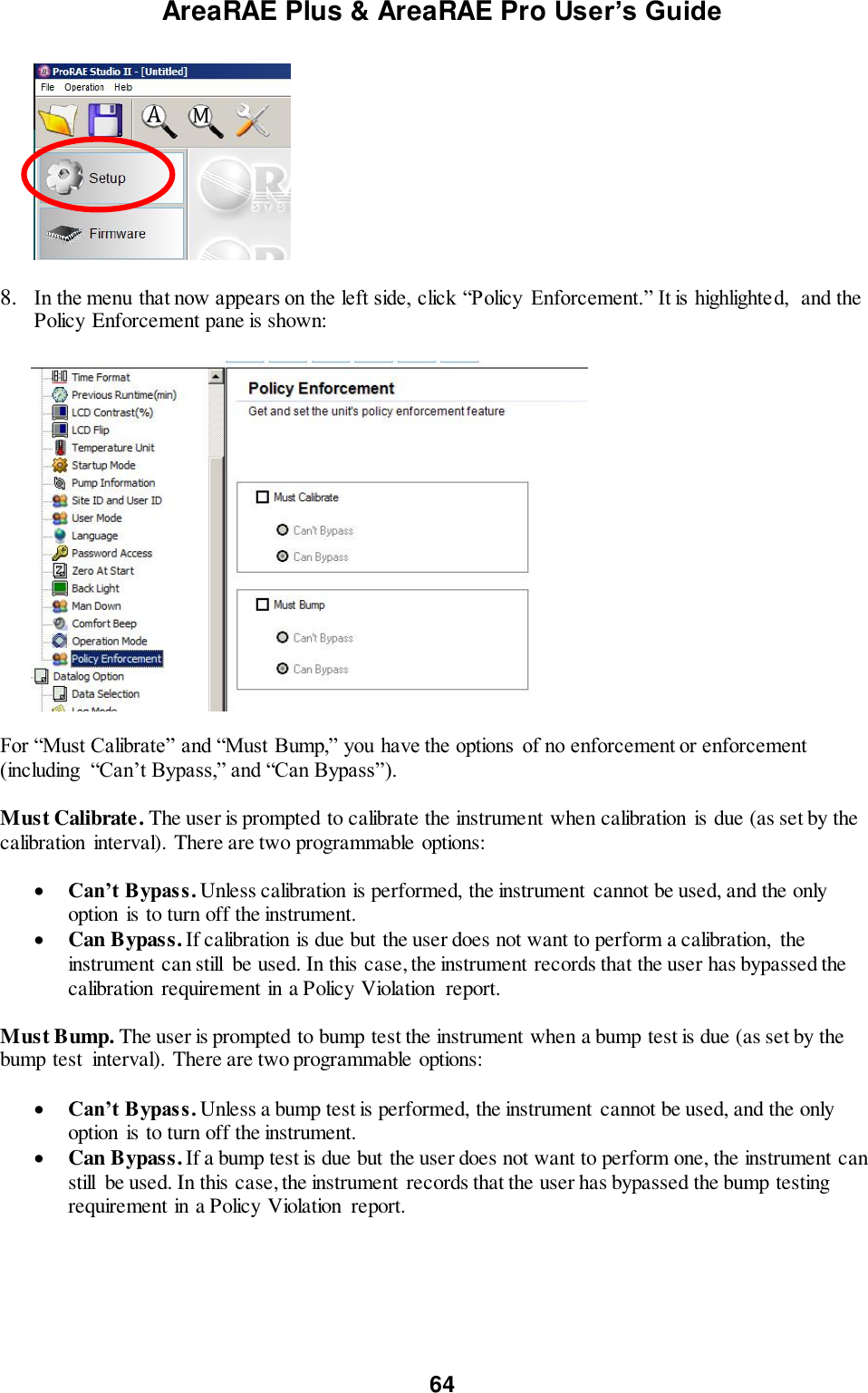
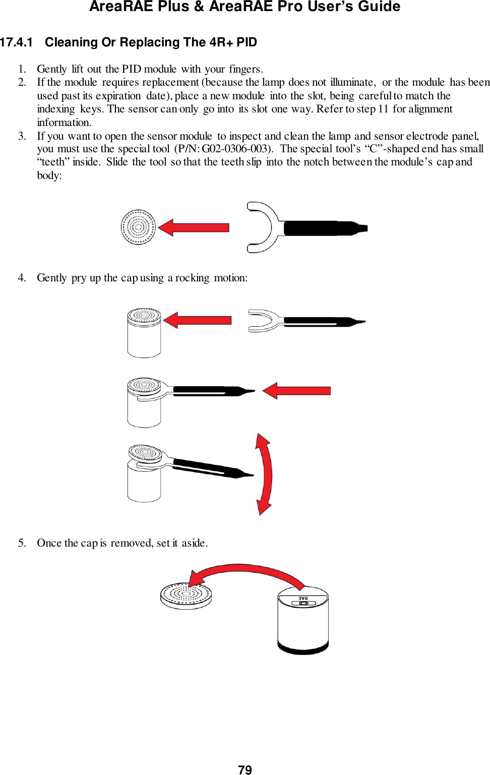
![AreaRAE Plus & AreaRAE Pro User’s Guide 65 These are the screens that are shown on an AreaRAE Plus/Pro after startup if “Can Bypass” is selected: If “Can’t Bypass” is selected, the display looks like this, and only allows the options of performing the test or shutting down: 16. Once you have made your selections in ProRAE Studio II, you must upload the changes to the instrument. Click the icon labeled “Upload all settings to the instrument.” 17. A confirmation screen is shown. Click “Yes” to perform the upload, or “No” to abort. Uploading takes a few seconds, and a progress bar is shown. You can abort the upload by clicking “Cancel.” 18. Exit ProRAE Studio II. 19. Press [Y/+] on the AreaRAE Plus/Pro to exit Communication Mode. 14.2 Deactivating Policy Enforcement If the AreaRAE Plus/Pro screen displays the message that it must be bump tested or calibrated, and if the option to bypass bump testing or calibration is not available, you should shut off the instrument and follow the procedure outlined here if you want to change the Policy Enforcement settings: 1. Use a USB cable to connect the AreaRAE to a computer running ProRAE Studio II. 2. Enter Diagnostic Mode on the AreaRAE Plus/Pro (with the instrument turned off, press and hold [Y/+] and [MODE] until it starts up. 3. After startup, enter the password when prompted (default is “0000”) and press [MODE]. 4. Press [N/-] repeatedly until you see the “Enter Communications Mode?” screen. 5. Press [Y/+] to enter Communications Mode. 6. Start ProRAE Studio II. 7. Select “Administrator.”](https://usermanual.wiki/RAE-Systems/6560A/User-Guide-3055882-Page-65.png)
![AreaRAE Plus & AreaRAE Pro User’s Guide 66 8. Input the password (the default is “rae”). 9. Click “OK.” 10. Click “A” (detect instruments automatically). 11. Click on the instrument’s icon when it appears. 12. Click “Select.” 13. Click “Setup.” 14. Click “Policy Enforcement.” The Policy Enforcement pane is shown. 15. Deselect Policy Enforcement features you do not wish to use. 16. Click “Upload all settings to the instrument.” 17. When you see this confirmation. Click “Yes.” Uploading will take a few seconds, and this progress bar is shown: 18. When the upload is done, exit ProRAE Studio II. 19. Press [Y/+] on the AreaRAE Plus/Pro to exit Communication Mode.](https://usermanual.wiki/RAE-Systems/6560A/User-Guide-3055882-Page-66.png)
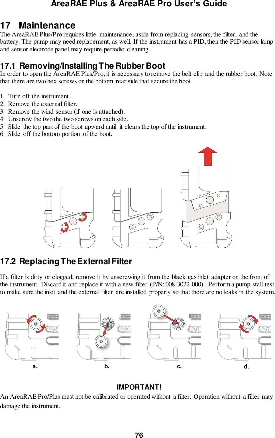
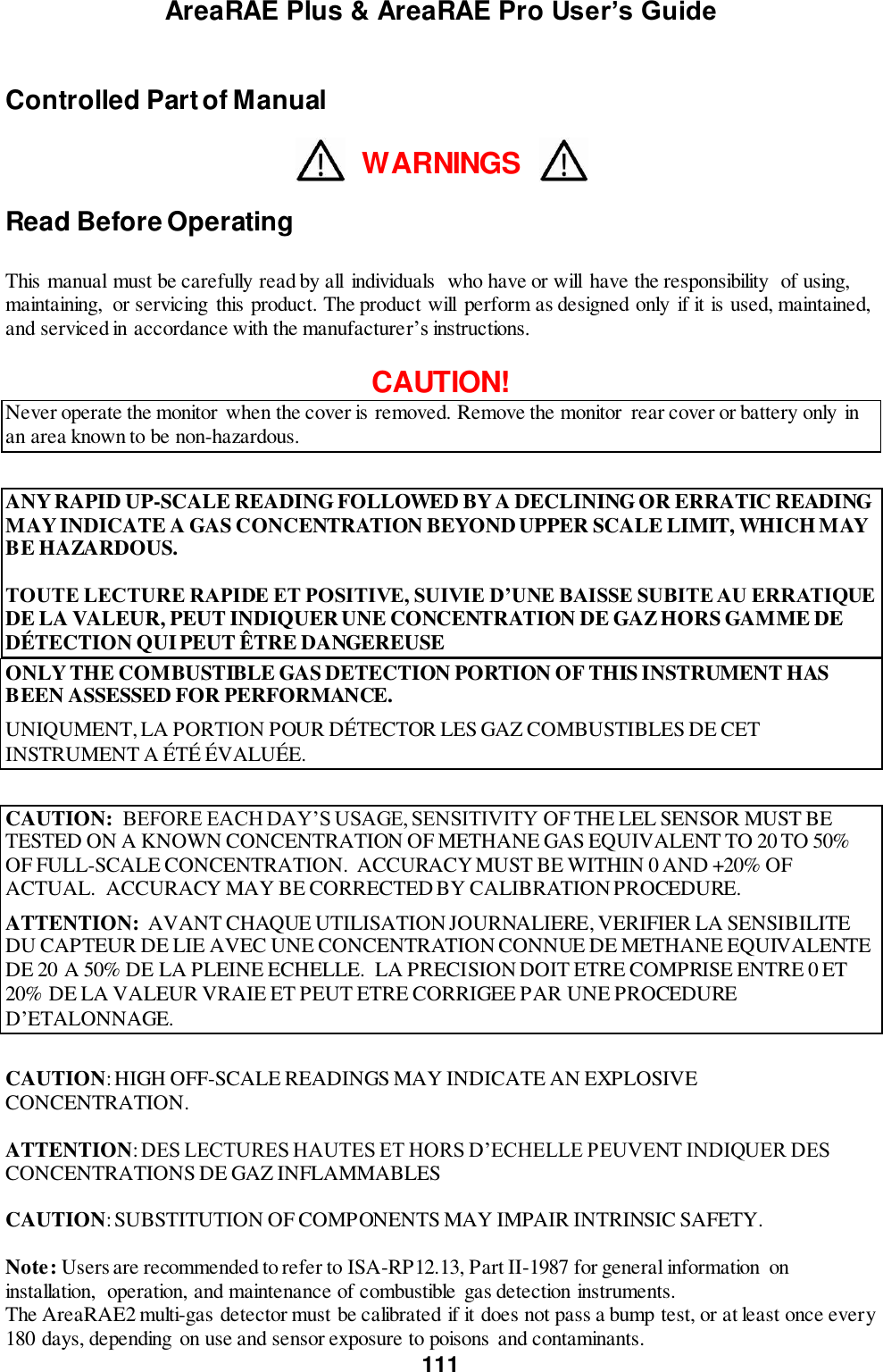
![AreaRAE Plus & AreaRAE Pro User’s Guide 67 15 Calibration And Testing 15.1 Manual Alarms Test Under Normal Operation Mode and non-alarm conditions, the buzzer (audible alarm), visible alarms, and backlight can all be tested anytime by pressing [Y/+] twice. If any alarm does not respond, check the alarm settings in the Programming Menu to make sure all alarms are enabled (selected setting under Programming/Alarms/Alarm Settings should be “All Enabled”). If any alarms are enabled but not functional, the instrument should not be used. 15.2 Bump Testing And Calibration RAE Systems recommends that a bump test be conducted prior to each day’s use. The purpose of a bump test is to ensure that the instrument’s sensors respond to gas and all the alarms are enabled and functional. The AreaRAE Plus/Pro multi-gas detector must be calibrated if it does not pass a bump test when a new sensor is installed, after sensor maintenance has been performed, or at least once every 180 days, depending on use and sensor exposure to poisons and contaminants. Calibration and bump test intervals and procedures may vary due to national legislation and company policy. During a bump test, the instrument makes a pass/fail decision based on sensor performance, but the user still has the responsibility to make sure all the alarms are enabled and functional. 15.2.1 Bump (Functional) Testing A bump test can be performed on an individual sensor (Single Sensor Bump) or a group of sensors (Multi Sensor Bump) combined into Multi Cal. Select. The same gas is used for a bump test as for calibration. Typically, two cylinders of calibration gas are needed to perform a bump test or calibration on an instrument with a PID sensor and electrochemical and LEL sensors. This may require one gas cylinder with Isobutylene or another VOC test gas to test the PID sensor, and another with a 4-gas mix to test electrochemical (such as CO, H2S, and O2) and LEL sensors. As with calibration, the instrument intelligently splits the process into two consecutive steps: first, the wizard prompts for testing electrochemical and LEL sensors, and then it tests the PID sensor. IMPORTANT! Make sure all of the instrument’s sensors have warmed up before performing a bump test. The instrument will take the time to warm up the sensors prior to enabling access to bump test menus. You can tell a sensor has warmed up if you see a reading next to it name on the display. If it has not warmed up, you see three dashes (“---”) next to it. Teflon tubing must be used to test or calibrate the PID sensor. Follow the steps described here to perform a manual bump test: 1. Turn on your AreaRAE Plus/Pro by pressing and holding [MODE] (the middle button) and allow the instrument to boot up fully until the main measurement screen with sensor names and readings is shown. 2. Enter the Bump Test menu. It is accessible either through Programming Menu.](https://usermanual.wiki/RAE-Systems/6560A/User-Guide-3055882-Page-67.png)
![AreaRAE Plus & AreaRAE Pro User’s Guide 68 3. Connect the AreaRAE Plus/Pro to the calibration gas. Turn on the gas to initiate flow. 4. Press [Y/+] to start the bump test. While the bump test is being performed, the readings for each sensor are shown. Once the bump test completes, pass/fail test results and readings are shown for each sensor. Note: If a PID or other sensors are installed in the instrument require a dedicated cylinder of gas to calibrate, the instrument will prompt for calibrating such sensors at this point. IMPORTANT! If one or more sensors fails a bump test, be sure to calibrate those sensors. 5. The bump test is now complete. Press Exit to return to the main measurement screen. 6. Now perform a manual alarms test (see page 67). If all the alarms and all sensors have passed and no sensor is due for a calibration, the instrument is now ready for use. Note: When a manual bump test is performed, the readings shown are in the equivalent units of the calibration gas, and not the measurement gas (if different).](https://usermanual.wiki/RAE-Systems/6560A/User-Guide-3055882-Page-68.png)
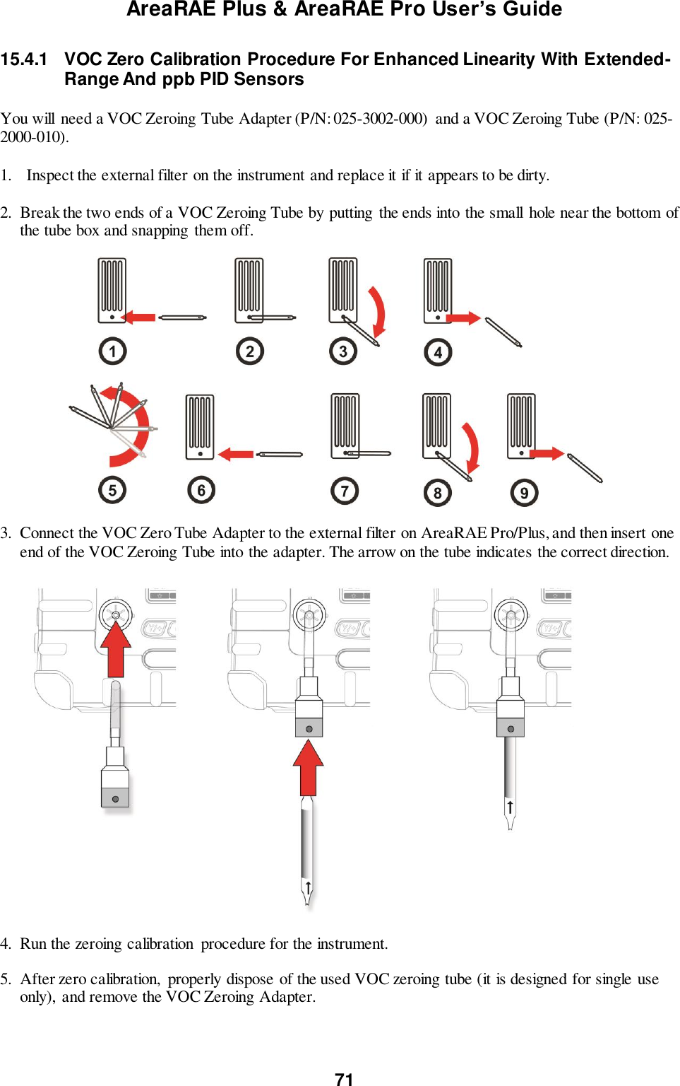
![AreaRAE Plus & AreaRAE Pro User’s Guide 69 15.2.2 Testing The Gamma Radiation Sensor The gamma radiation sensor does not require user calibration. To check whether the sensor is operational, place a gamma check-source on the upper half of the rear of the AreaRAE Plus/Pro equipped with a gamma sensor. The reading should increase. 15.2.3 Zero Calibration For Parts-Per-Billion (ppb) PID Sensor IMPORTANT! The parts-per-billion PID sensor for volatile organic compounds (VOCs) should not be zeroed in fresh air. VOCs are normally present in ambient air, so zeroing the sensor in ambient air will not allow for a true zero to be set. The parts-per-billion PID sensor should be zeroed with ambient air using a charcoal filter or a VOC zeroing tube. Refer to the procedure on page 71. 15.2.4 Fresh Air Calibration This procedure determines zero points of most sensors. The AreaRAE Plus/Pro should be zero-calibrated in clean air with 20.9% oxygen or with a cylinder of clean zero air. Note: If you use a zero air cylinder, you must connect it directly to the filter that is attached to the instrument’s inlet. At the Calibration menu, select “Fresh Air” by pressing [Y/+] once to enter fresh air calibration. After a timer countdown, the zero calibration is done. The LCD displays the sensor names and tells you whether each calibration passed or failed, followed by the sensor readings. Note: You can abort the calibration at any time during the countdown by pressing [N/-].](https://usermanual.wiki/RAE-Systems/6560A/User-Guide-3055882-Page-69.png)
![AreaRAE Plus & AreaRAE Pro User’s Guide 72 15.4.2 Enabling 3-Point Calibration Via ProRAE Studio II The AreaRAE Plus/Pro must be connected to a PC through the supplied USB cable and must be in the PC Communications mode. 1. Start up the ProRAE Studio II software, enter a password, and detect the instrument following the directions provided in the ProRAE Studio II User’s Manual. 2. Click “Setup” to download the AreaRAE Plus/Pro’s current configuration information 3. Click “Sensor Information.” 4. Click the “+” to the left of “Sensor Summary” to show the list of installed sensors. 5. Click “VOC(ppm)” or “VOC(ppb)” to get and set sensor parameters. 6. Click 3-Point Calibration (the check mark should now be showing). 7. Click the “Upload all settings to the instrument” icon. You will be asked whether you want to upload all configurations to the instrument. Click “Yes.” 8. When you are done, quit ProRAE Studio II and then press [Y/+] on the AreaRAE Plus/Pro to exit the PC communications mode. The instrument returns to operating in Normal mode. 15.4.3 Calibration Setup For single-sensor and multi-sensor span calibration, there are three methods for calibrating. Each has different regulator type, flow rate, and pressure compensation requirements: Regulator Type Flow Rate T-Tube Necessary? Good Constant Flow 500 cc/min No Better Constant Flow 750 cc/min Yes Best Demand Flow -- No Using A T-Tube Using Teflon tubing, attach one end of a “T” to the external filter on the AreaRAE Plus/Pro inlet. (You can use RAE Systems P/N: W01-3003-000). Calibrating Without A T-Tube Use Teflon tubing to connect the calibration gas cylinder’s regulator to the external filter on the AreaRAE Plus/Pro inlet.](https://usermanual.wiki/RAE-Systems/6560A/User-Guide-3055882-Page-72.png)
![AreaRAE Plus & AreaRAE Pro User’s Guide 73 Multi-Sensor Span Calibration This lets you perform a span calibration on multiple sensors simultaneously. It requires using the appropriate span gas and that the concentration labeled on the gas cylinder matches the concentration programmed in the AreaRAE Plus/Pro. Teflon tubing must be used to test or calibrate the PID sensor. Follow the steps described here to perform a multi-sensor span calibration: 1. Attach the “T” tube and connect gas to the AreaRAE Plus/Pro. 2. Start the flow of gas and then either press [Y/+] to begin calibration or wait for calibration to start automatically once the sensor “senses” the gas. A countdown screen is shown. You can abort the calibration at any time during the countdown by pressing [N/-]. If the calibration reaches its conclusion, it shows the sensor names and tells you whether the calibration passed or failed, followed by the sensor readings. Note: If there are other sensors to be calibrated at this stage, the screens will guide you through the process.](https://usermanual.wiki/RAE-Systems/6560A/User-Guide-3055882-Page-73.png)
![AreaRAE Plus & AreaRAE Pro User’s Guide 74 15.4.4 Single-Sensor Span Calibration To perform span calibration of an individual sensor, follow these steps: 1. At the Calibration Menu, select “Single Sensor Span.” 2. Select a sensor from the list. 3. Connect the “T” tube and connect it to a source of calibration gas. 4. Verify that the displayed calibration value meets the concentration label on the gas cylinder. 5. Start the flow of calibration gas. 6. Press [Y/+] to start calibrating. You can abort the calibration at any time during the countdown by pressing [N/-]. After a timer countdown, the span calibration is done. The LCD will display whether the calibration was successful and the reading for that calibration gas. Note: If the sensor calibration fails, try again. If calibration fails repeatedly, turn off the instrument and then replace the sensor. WARNING: Do not replace sensors in hazardous locations.](https://usermanual.wiki/RAE-Systems/6560A/User-Guide-3055882-Page-74.png)
![AreaRAE Plus & AreaRAE Pro User’s Guide 75 16 Datalog Transfer, Monitor Configuration, and Firmware Upgrades Via Computer Datalogs can be downloaded from the AreaRAE Plus/Pro to a computer, and firmware updates can be uploaded to the AreaRAE Plus/Pro via the USB port on the side. Use the included USB cable to connect the AreaRAE Plus/Pro to a computer running ProRAE Studio II. 16.1 Downloading Datalogs And Performing PC-Based Instrument Configuration And Firmware Upgrades The AreaRAE Plus/Pro communicates with a PC running ProRAE Studio II Instrument Configuration and Data Management software to download datalogs, configure the instrument, or upgrade the instrument’s firmware. Note: The most recent version of ProRAE Studio II Instrument Configuration and Data Management software is available for a free-of-charge download at: http://www.raesystems.com/downloads/product-software . 1. Use the supplied PC Communications Cable to connect the AreaRAE Plus/Pro to a PC. 2. Turn on the AreaRAE Plus/Pro. Make sure it is running in Normal mode (with the main measurement screen showing). 3. Activate the PC communications mode on the AreaRAE Plus/Pro by pressing [N/-] repeatedly, starting from the main measurement screen until you reach the “Enter Communication Mode?” screen. 4. Press [Y/+]. Measurement and datalogging stop, and the instrument is now ready to communicate with the PC. The display now says “Ready To Communicate With Computer.” 5. Start up the ProRAE Studio II software, enter a password, and detect the instrument following the directions provided in the ProRAE Studio II User’s Guide. 6. Follow the instructions in the ProRAE Studio II User’s Guide to download the datalog, configure the instrument settings, or update the AreaRAE Plus/Pro’s firmware. 7. When you are done, press [Y/+] to exit the PC communications mode on the AreaRAE Plus/Pro. The instrument returns to operating in Normal mode. IMPORTANT! Always securely close the cover over the USB port when it is not in use. This keeps moisture and debris out of the port. USB cable USB port](https://usermanual.wiki/RAE-Systems/6560A/User-Guide-3055882-Page-75.png)
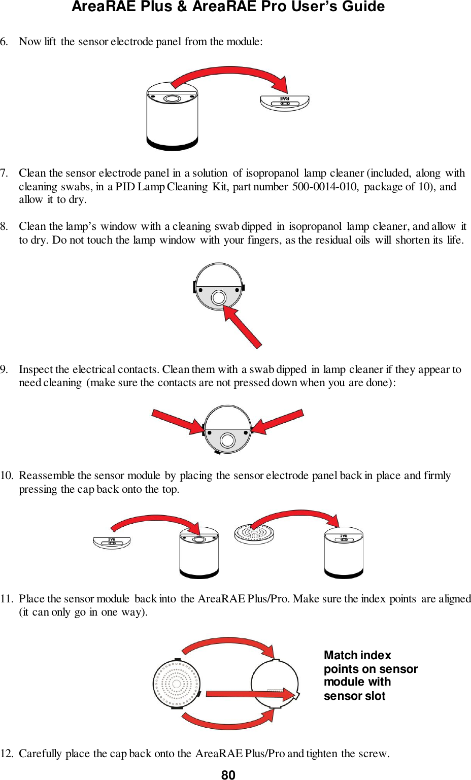
![AreaRAE Plus & AreaRAE Pro User’s Guide 96 18 Alarms Overview The AreaRAE Plus/Pro provides an unmistakable four-way alarm notification system that combines local alarms on the device with real-time remote wireless alarm notification (if the instrument is equipped wireless functionality and it is active). Local alarms include audible buzzer alarm, visible alarm via bright LED lights, and an alarm notification on the display. These can be selectively turned on or off. 18.1 Alarm Signals During each measurement period, the gas concentration and radiation levels are compared with the programmed alarm limits for Low, High, TWA, STEL, and other alarms, as applicable. If the concentration exceeds any of the preset limits, the alarms are activated immediately to warn both the AreaRAE Plus/Pro user and a remote safety officer (if wireless is enabled) of the alarm condition. In addition to gas and radiation alarms, other alarms are available. Furthermore, the AreaRAE Plus/Pro alarms if one or more of the following conditions occurs: battery voltage low, pump blocked, PID lamp failed, etc. When the low battery alarm occurs, there may be approximately 15 minutes of operating time remaining. In this case, it is recommended that you promptly change or charge the battery in a non-hazardous location. 18.2 Changing The Alarm Mode Your choices are Auto Reset and Latched. A latched alarm stays on until you acknowledge the alarm by pressing a button. An auto-reset alarm turns off when the condition that set off the alarm is no longer present (for instance, a high H2S reading that exceeds the preset threshold and triggers an alarm, but then lowers below that threshold, turning the alarm off). 1. Enter the Alarm Mode sub-menu of the Alarms section under the Programming Menu. 2. Select Auto Reset or Latched by pressing [N/-] to select the mode, and [Y/+] to confirm the choice. 3. Press [Y/+] to save your selection.](https://usermanual.wiki/RAE-Systems/6560A/User-Guide-3055882-Page-96.png)
![AreaRAE Plus & AreaRAE Pro User’s Guide 97 19 Diagnostic Mode In Diagnostic Mode, the AreaRAE Plus/Pro provides raw counts for sensor, battery, and other readings, as well as a list of installed sensors and information about them (expiration date, serial number, etc.). Most of these screens are useful only to service technicians. Many allow access for changing settings. Diagnostic Mode can only be accessed at startup time. In Diagnostic Mode, readings are displayed in raw counts instead of parts per million (ppm) or other units of measure. 19.1 Enter Diagnostic Mode 1. With the instrument turned off, press and hold [Y/+] and [MODE] until the AreaRAE Plus/Pro starts up. 2. After startup, enter the password when prompted (default is “0000”) and press [MODE]. Once Diagnostic Mode is active, step from screen to screen by pressing [N/-]. 19.2 Adjusting Alarm LEDs & Buzzer The buzzer, green LEDs, red LEDs, and backlight can be turned on or off in Diagnostic mode. In addition, you can adjust the repetition rate and loudness of the buzzer and the repetition rate and brightness of the LEDs. 1. Start with the instrument turned off. Hold down the [Y/+] and [MODE] keys until the AreaRAE Plus/Pro starts. 2. When you see the password screen, input your 4-digit password, and then press [MODE]. 3. Once you have entered Diagnostic Mode, press [N/-] until the “Alarm” screen is displayed. 4. Press [MODE] to step through the menu items; press [Y/+] to make a change, and press [N/-] to advance to the next menu. Important! When you are done, exit Diagnostic Mode and test the instrument before actual use. 19.3 Adjusting LCD Contrast The display’s contrast can be adjusted in Diagnostic mode. 1. Start with the instrument turned off. Hold down the [Y/+] and [MODE] keys until the AreaRAE Plus/Pro starts. 2. When you see the password screen, input your 4-digit password, and then press [MODE]. 3. Once you have entered Diagnostic Mode, press [N/-] until the “LCD Contrast” screen is displayed. 4. Press [Y/+] to increase the value; press [MODE] to decrease the value, and press [N/-] to advance to the next menu. Important! When you are done, exit Diagnostic Mode and test the instrument before actual use. 19.4 Pump Stall Threshold Adjustment Proper setting of the pump stall threshold is necessary so that if there is an obstruction to the inlet, the pump will stop and the instrument will go into alarm. This prevents unwanted debris or liquid from entering the pump and causing disruption or damage. The AreaRAE Plus/Pro provides two methods to set the pump stall threshold: Static and Dynamic. Note: The Dynamic method uses an algorithm that takes external temperature into consideration for greater accuracy.](https://usermanual.wiki/RAE-Systems/6560A/User-Guide-3055882-Page-97.png)
![AreaRAE Plus & AreaRAE Pro User’s Guide 98 If it is necessary to set the pump stall threshold, you must enter Diagnostic Mode. Also, regardless of which method is used, when you are done setting thresholds, exit Diagnostic Mode and test the instrument before actual use. 19.4.1 Entering Diagnostic Mode To Set The Pump Stall Threshold 5. Start with the instrument turned off. Hold down the [Y/+] and [MODE] keys until the AreaRAE Plus/Pro starts. 6. When you see the password screen, input your 4-digit password, and then press [MODE]. 7. Once you have entered Diagnostic Mode, press [N/-] until the “Pump” screen is displayed. 8. Set the high and low threshold settings for pump stall using the instructions in this section. Press [MODE] to step through the menu items; press [Y/+] to make a change, and press [N/-] to advance to the next menu. 19.4.2 Selecting The Pump Stall Threshold Method At the Pump screen, the settings are shown, including the Pump Speed and Pump Stall Algorithm (which can be Dynamic or Static). To change the pump Speed or Stall Algorithm setting: 1. Press [MODE]. Either the pump Speed or the Stall Algorithm is highlighted. 2. To change from “High” to “Low” or “Dynamic” to “Static,” press [Y/+]. Important! The pump Speed must be set to “High” in order to access Dynamic pump stall settings. Now follow directions to change the pump stall threshold values, using the method that matches your choice of either Dynamic or Static.](https://usermanual.wiki/RAE-Systems/6560A/User-Guide-3055882-Page-98.png)
![AreaRAE Plus & AreaRAE Pro User’s Guide 99 19.4.3 Setting Pump Stall Threshold Values – Dynamic Method When the Dynamic pump stall threshold values are shown, you can perform calibration to set the pump stall values dynamically. Press [MODE] to begin calibration. This screen is shown, indicating that it is ready: Press [MODE] to begin calibration. There is a countdown shown in the box. Press [N/-] anytime to abort the calibration and go back.](https://usermanual.wiki/RAE-Systems/6560A/User-Guide-3055882-Page-99.png)
![AreaRAE Plus & AreaRAE Pro User’s Guide 100 Once the countdown is finished, this message is displayed: Hold your finger over the inlet, and allow the countdown to proceed. Press [Y/+] anytime to abort and return to the previous screen. When the countdown is finished, the main Dynamic pump stall screen is shown. Dynamic pump stall calibration is complete. You can now exit Diagnostic Mode.](https://usermanual.wiki/RAE-Systems/6560A/User-Guide-3055882-Page-100.png)
![AreaRAE Plus & AreaRAE Pro User’s Guide 101 Important! When you are done setting thresholds, exit Diagnostic Mode and test the instrument before actual use. 19.4.4 Setting Pump Stall Threshold Values – Static Method Use the following values for reference when using the Static method to adjust the pump stall threshold values: Low Speed High Speed Vacuum ≤ -2.5in Hg ≤ -10in Hg Flow rate >200 cc/min >400 cc/min Idle (I) 100 to 200 counts 150 to 250 counts Block (Block-Idle) > 100 counts (Block-idle) > 100 counts Stall Setting (Idle + Block)/2 (Idle + Block)/2 Stall High Threshold Setting – Static Method In Diagnostic Mode, press the [MODE] key repeatedly until the “Pump” screen is displayed. “High” should be highlighted. Otherwise, press [Y/+] to select the “High” value. The Idle value (shown as a value for “I”) should be 150 to 250. Record the value. Block the inlet, and record the value after it goes up. The blocked value minus the Idle (Unblocked) value should be greater than 100 counts: (Blocked value – Unblocked value) > 100. If it is greater than 100, then the pump is working correctly and tubing leading from the inlet is not leaking. To calculate the best High value, first add the Blocked and Unblocked values and divide by 2: (Blocked value + Unblocked value) / 2 = correct Stall High value. Press [N/-] to advance to the next Pump screen. Use the [Y/+] and [N/-] keys to increase or decrease the high value input the results of your calculation. Press [MODE] to register that value.](https://usermanual.wiki/RAE-Systems/6560A/User-Guide-3055882-Page-101.png)
![AreaRAE Plus & AreaRAE Pro User’s Guide 102 Verifying the Stall High Setting Exit Diagnostic Mode. In Normal Mode, with the pump at high speed, block the inlet. The pump should stall after a few seconds, sending the instrument into alarm. This tells you that the pump’s Stall High setting is correct. If the gas inlet is blocked but the pump does not shut down, or the pump shuts down too easily with a slight blockage, the pump stall threshold value may be set too high or too low. If the pump does not stall or send the instrument into alarm, then there may be a leak in the gas inlet or the pump is weak or defective and should be replaced. Stall Low Threshold Setting - Static In Diagnostic Mode, press the [MODE] key repeatedly until the “Pump” screen is displayed. “Low” should be highlighted. Otherwise, press [Y/+] to select the “Low” value. The Idle (shown as a value for “I”) value should be 100 to 200. Record the value. Block the inlet, and record the value after it goes up. The blocked value minus the idle (unblocked) value should be greater than 100 counts: (Blocked value – Unblocked value) > 100 If it is greater than 100, then the pump is working correctly and tubing leading from the inlet is not leaking. To set the Low value, first add the blocked and unblocked values and divide by 2: (Blocked value + Unblocked value) / 2 = correct Stall Low value Then, using the [Y/+] and [N/-] keys, set the Stall Low value to this number. Verifying the Stall Low Setting - Static Exit Diagnostic Mode. In Normal Mode, block the inlet. The pump should stall after a few seconds, sending the instrument into alarm. This tells you that the pump’s Low setting is correct. If the gas inlet is blocked but the pump does not shut down, or the pump shuts down too easily with a slight blockage, the pump stall threshold value may be set too high or too low. If the pump does not stall and send the instrument into alarm, then there may be a leak in the gas inlet or the pump is weak or defective and should be replaced. Important! When you are done setting thresholds, exit Diagnostic Mode and test the instrument before actual use. 19.5 Exit Diagnostic Mode Hold [MODE] until the AreaRAE Plus/Pro shuts off. When you start it up again, it is in normal operating mode.](https://usermanual.wiki/RAE-Systems/6560A/User-Guide-3055882-Page-102.png)
![AreaRAE Plus & AreaRAE Pro User’s Guide 105 20 Troubleshooting Problem Possible Reasons & Solutions Cannot turn on power after charging the battery Reasons: Defective charging circuit. Defective battery. Solutions: Replace battery or charger. Try charging battery again. Lost password Solutions: Call Technical Support at +1 408-952-8461 or toll-free at +1 888-723-4800 Buzzer, LED lights inoperative Reasons: Buzzer and/or other alarms disabled. Bad buzzer, LED lights, or PCB. Solutions: Check under “Alarm Settings” in Programming Mode that buzzer and/or other alarms are not turned off. Call authorized service center. “Lamp” message when power on. Lamp alarm. Reasons: Low ion concentration inside PID lamp especially in cold environment when first powered on. Defective PID lamp or defective circuit. Solutions: Turn the unit off and back on. Replace UV lamp. Pump failed message. Pump alarm. Reasons: Inlet probe blocked. Direct connection to a gas outlet while the gas value is turned off. Water trap filter sucks in water. Water trap filter too dirty. Water condensed along the inlet probe. Bad pump or pump circuit. Solutions: Remove the blocking objects and then press [Y/+] key to reset the pump alarm. Replace contaminated water trap filter. Be careful not to allow water condensation inside the unit. Replace the pump. If you need replacement parts, a list is available online: www.raesystems.com](https://usermanual.wiki/RAE-Systems/6560A/User-Guide-3055882-Page-105.png)
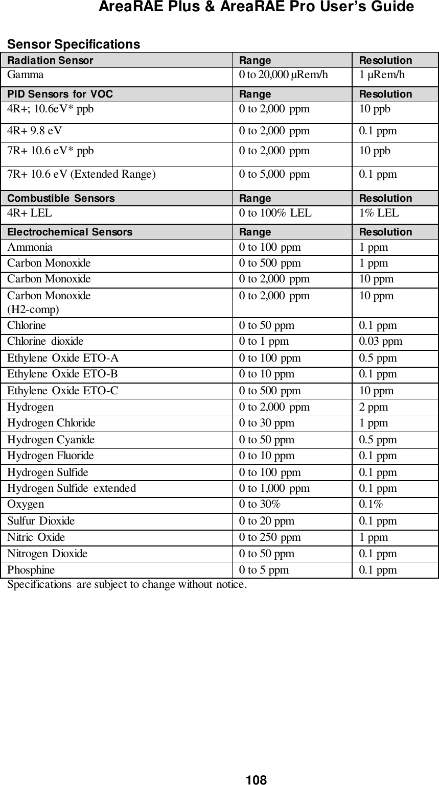
![AreaRAE Plus & AreaRAE Pro User’s Guide 106 21 Specifications Dimensions 12.6″ x 12.4″ x 6.3″ (322 mm x 315 mm x 160 mm) with boot Weight 13.67 lbs (6.3 kg) Gas Sensor Slots 7 total; see Sensor list on this page Additional Sensors* Gamma, RAEMet (wind speed, wind direction, temperature, humidity) GPS Installed at factory Battery Rechargeable 7.2V/10AH Li-ion battery pack with built-in charger Alkaline adapter with 5 D-size batteries Battery Charging Time <10 hrs Operating Hours Approximately 16 hours with wireless connectivity, GPS, and all sensors operational Power input AC adapter with Input 110-240 V AC Display Large 240x320 pixel LCD display 2.5″ x 3.34″ (63.59 mm x 84.79 mm) Keypads 3 operation and programming keys Alarms High/Low limits for gases and radiation detectors, STEL, TWA limits for EC sensors, low battery, sensor, or pump failure Visible Alarm Bright LED, 360-degree view Audible Alarm Dual buzzers: 108 dB @ 1 m Data logging Continuous datalogging (90 days for 12 gas sensors and GPS at 1-minute intervals, continuously) Data Storage 24M bytes (memory-full action: stop when full or wrap-around) Data Interval User-configurable from 1 to 3,600 sec Wireless Long Range: ISM License-free 900 to 928 MHz or 2.4GHz Optional WiFi Secondary: Mesh Network FCC Compliance FCC Part 15 Communication Communicates to ProRAE Studio via USB cable to PC; Wireless data and alarm status transmission via Wi-Fi or ISM modem; Acts as gateway to connect up to 8 remote Mesh-module equipped instruments Safety Certification Class I, Division 2 Groups A, B, C, D ATEX Zone 2 (II 3G Ex nA [ic Gc] IIC T4 Gc) IECEx (Ex n IIC T4 Gc) Ex n IIC T4 Gc (China) Sampling Pump Built-in pump, typical flow rate 450 cc/min Temperature -20° C to 50° C (-4° F to 122° F) Humidity 0% to 95% relative humidity (non-condensing) Ingress Protection (IP) IP-65 (third-party tested)](https://usermanual.wiki/RAE-Systems/6560A/User-Guide-3055882-Page-106.png)

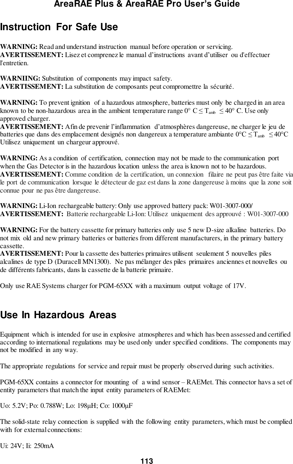
![AreaRAE Plus & AreaRAE Pro User’s Guide 112 CAUTION! TheAreaRAE, PGM-65XX, shall only be charged using a charger specifically supplied for use with the unit with a maximum output voltage of 17V. Use of non-RAE Systems components will void the warranty and can compromise the safe performance of this product. PGM-65XX Marking The PGM-65XX is certified according to the IECEx scheme, ATEX and CSA for US and Canada under the non-sparking safety method of protection. The PGM-65XX is marked with the following information: RAE SYSTEMS 3775 N. 1st. St., San Jose CA 95134, USA Type PGM-65XX. Serial No/barcode: XXXX-XXXX-XX IECEx XXX15.XXXX Ex ic nA [ic] IIC T4 Gc XXX 15 ATEX XXXX II 3G Ex ic nA [ic] IIC T4 Gc Cl.I Dv 2, Grps A,B,C,D T-Code T4. C22.2 No.152-M1984 ANSI/ISA-12.13.01-2013 -20º C < Tamb < +50º C; Um:17V RAEMet connection:Uo: 5.2V, Po: 0.788W, Lo:198μH, Co:1000μF SSRelay connection: Ui: 24V, Ii:250mA Battery pack: W01-3007-000 CAUTION: READ AND UNDERSTAND INSTRUCTION MANUAL BEFORE OPERATING OR SERVICING ATTENTION: LIRE ET COMPRENDRE MANUEL D’INSTRUCTIONS AVANT D’UTILISER OU SERVICE Operation Area and Conditions Hazardous Areas Classified by Zones PGM-65XX are intended to be used in hazardous areas classified zone 2 within the temperature range of -20ºC to +50ºC, where gases of explosion groups IIA, IIB or IIC and T4 may be present. Hazardous Areas classified by Divisions PGM-65XX is intended to be used in hazardous areas classified for Class I Div. 2, within the temperature range of -20º C to +50º C, where gases of explosion groups A, B, C or D and temperature code T4 may be present.](https://usermanual.wiki/RAE-Systems/6560A/User-Guide-3055882-Page-112.png)
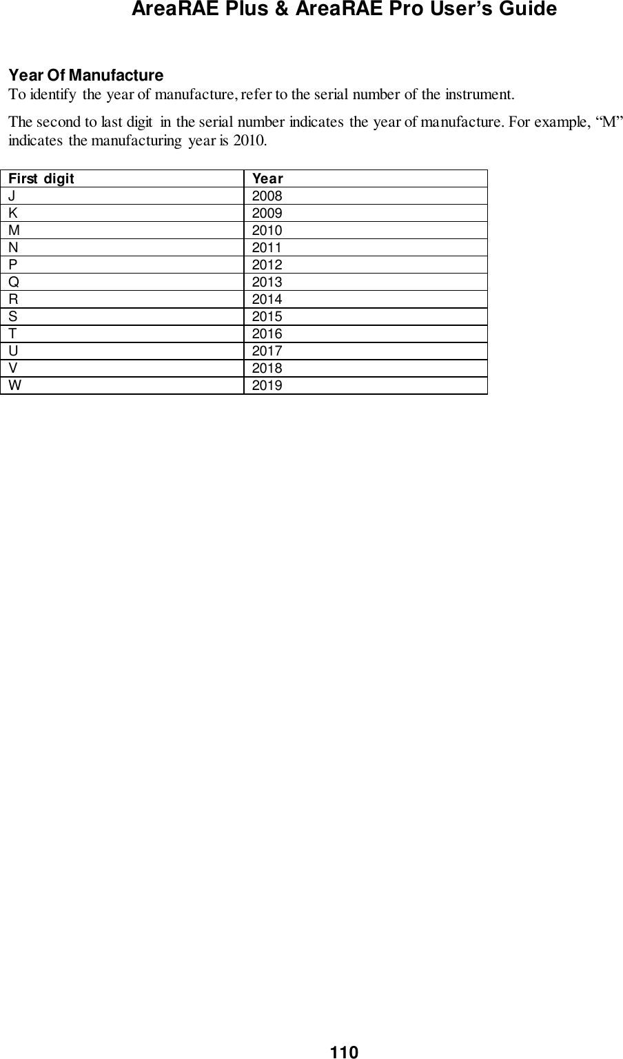
![AreaRAE Plus & AreaRAE Pro User’s Guide 114 Year of manufacture To identify the year and month of manufacture, refer to the two digit marking placed adjacent to the serial number on the instrument label according to the following table: Year First digit Year code Month Second digit Month code 2014 R January 1 2015 S February 2 2016 T March 3 2017 U April 4 2018 V May 5 2019 W June 6 2020 A July 7 2021 B August 8 2022 C September 9 2023 D October A 2024 E November B 2025 F December C E.g.: “RA” indicates that the monitor was manufactured in the month of October in the year 2014. Turning the PGM-65XX On With the instrument turned off, press and hold the [MODE] key for 3 seconds, and then release. The startup process begins. The instrument performs a set of self-tests, while displaying information about instrument’s settings, configuration, due dates for calibration and bump tests, etc. When the startup completes, the PGM-65XX displays its normal measurement screen with instantaneous readings and other information. Pausing To View Screens During Startup Press the [MODE] button anytime during the startup sequence to pause the progression. This allows you to view the information for as long as you like. To resume the progression, press [MODE] again. Even if you pause the progression of screens, the startup process is not interrupted. Note: To speed up the startup time, the number of screens shown on startup can be reduced by enabling the Fast Startup option under Programming/Monitor. Then the PGM-65XX’s main reading screen appears. It displays instantaneous readings similar to the following screen (depending on the sensors installed) and is ready for use. Note: If the battery is completely empty, then the display briefly shows the message “Battery Fully Discharged,” and the PGM-65XX shuts off. You should charge the battery or replace it with a fully charged battery before turning it on again. Turning the PGM-65XX Off Press and hold [MODE]. A 5-second countdown to shutoff begins. You must hold your finger on the key for the entire shutoff process.](https://usermanual.wiki/RAE-Systems/6560A/User-Guide-3055882-Page-114.png)
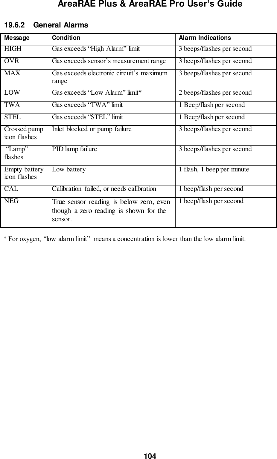
![AreaRAE Plus & AreaRAE Pro User’s Guide 115 Alarm Signals The instrument is equipped with audible, visible, and vibration alarms. During its normal operation, the PGM-65XX compares gas concentrations to the programmed alarm limits for Low, High, TWA and STEL alarms. If the concentration exceeds any of the preset limits, the loud buzzer, and red flashing LEDs are activated immediately to warn of the alarm condition. In addition, the PGM-65XX alarms if the battery voltage is low, pump is blocked, etc. When a low-battery alarm occurs, there may be approximately 20 to 30 minutes of operating time remaining. However, it is recommended that you promptly change or charge the battery in a non-hazardous location. Alarms Summary Testing Alarms Under normal operation mode and non-alarm conditions, the audible, visual, and vibration alarms can be tested at any time by pressing the [Y/+] key. Programming Menu Programming Menu is used to change instrument configuration settings can be entered from Normal Mode by pressing and holding [MODE] and [N/-] together for more than 3 seconds and supplying a password when prompted. Message Condition Alarm Indications HIGH Gas exceeds “High Alarm” limit 3 beeps/flashes per second OVR Gas exceeds sensor’s measurement range 3 beeps/flashes per second MAX Gas exceeds electronic circuit’s maximum range 3 beeps/flashes per second LOW Gas exceeds “Low Alarm” limit* 2 beeps/flashes per second TWA Gas exceeds “TWA” limit 1 Beep/flash per second STEL Gas exceeds “STEL” limit 1 Beep/flash per second Crossed pump icon flashes Inlet blocked or pump failure 3 beeps/flashes per second “Lamp” flashes PID lamp failure 3 beeps/flashes per second Empty battery icon flashes Low battery 1 flash, 1 beep per minute CAL Calibration failed, or needs calibration 1 beep/flash per second NEG True sensor reading is below zero, even though a zero reading is shown for the sensor. 1 beep/flash per second * For oxygen, “low alarm limit” means a concentration is lower than the low alarm limit.](https://usermanual.wiki/RAE-Systems/6560A/User-Guide-3055882-Page-115.png)
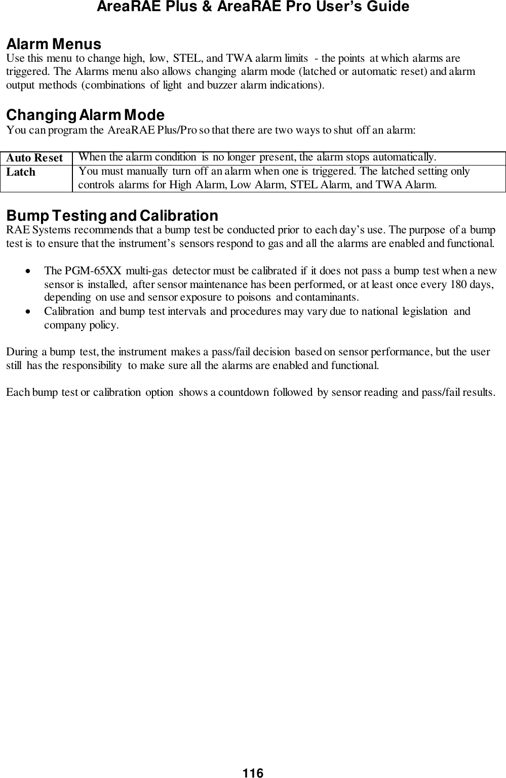
![AreaRAE Plus & AreaRAE Pro User’s Guide 117 Bump Testing A bump test can be performed on an individual sensor (Single Sensor Bump) or a group of sensors (Multi Sensor Bump) combined into Multi Cal. Select. The same gas is used for a bump test as for calibration. Typically, two cylinders of calibration gas are needed to perform a bump test or calibration on an instrument with a PID sensor and electrochemical and LEL sensors. This may require one gas cylinder with Isobutylene or another VOC test gas to test the PID sensor, and another with a 4-gas mix to test electrochemical (such as CO, H2S, and O2) and LEL sensors. As with calibration, the instrument intelligently splits the process into two consecutive steps: first, the wizard prompts for testing electrochemical and LEL sensors, and then it tests the PID sensor. For a manual bump test, a constant-flow regulator producing 0.75 to 1 liters per minute should be used. Attach one end of a “T” using Teflon tubing to the filter on the PGM-65XX inlet. (You can use RAE Systems P/N: W01-3003-000). Teflon tubing must be used to test or calibrate the PID sensor. Follow the steps described here to perform a manual bump test: 1. Turn on your PGM-65XX by pressing and holding [MODE] (the middle button) and allow the instrument to boot up fully until the main measurement screen with sensor names and readings is shown. IMPORTANT! Make sure all of the instrument’s sensors have warmed up before performing the bump test. The instrument will take the time to warm up the sensors prior to enabling access to bump test menus. You can tell a sensor has warmed up if you see a reading next to it name on the display. If it has not warmed up, you see three dashes (“---”) next to it. 2. Enter the Bump Test menu. It is accessible either through Programming Menu. 3. Connect the PGM-65XX to the calibration gas. Turn on the gas to initiate flow. 4. Press [Y/+] to start the bump test. While the bump test is being performed, the readings for each sensor are shown. Once the bump test completes, pass/fail test results and readings are shown for each sensor. Note: If a PID or other sensors are installed in the instrument require a dedicated cylinder of gas to calibrate, the instrument will prompt for calibrating such sensors at this point. 5. If a PID or other sensors installed in the instrument require a dedicated gas cylinder to calibrate, the instrument will prompt to calibrate such sensors at this point. Disconnect the gas cylinder and connect the next (for example, 10 ppm Isobutylene for a 4R+ ppb PID and the next gas should be 100 ppm; 100 ppm for 7R+ PID, and the next gas 1000 ppm).](https://usermanual.wiki/RAE-Systems/6560A/User-Guide-3055882-Page-117.png)
![AreaRAE Plus & AreaRAE Pro User’s Guide 118 6. Press “OK” to proceed to the PID sensor test. Turn on the gas and press Start ([Y/+] button). While the bump test is being performed, PID sensor readings are shown. Once the bump test completes, pass/fail test results and readings are shown for the PID sensor. Note: If other installed sensors require a dedicated cylinder of gas to calibrate, the instrument prompts for calibrating these sensors at this point. IMPORTANT! If one or more sensors fails a bump test, be sure to calibrate those sensors. 7. The bump test is now complete. Press Exit to return to the main measurement screen. 8. Now perform a manual alarms test. If all the alarms and all sensors have passed and no sensor is due for a calibration, the instrument is now ready for use. Note: When a manual bump test is performed, the readings shown are in the equivalent units of the calibration gas, and not the measurement gas (if different). Zero Calibration The instrument should be zero calibrated in clean ambient air with 20.9% oxygen. A zero calibration should precede a span calibration. IMPORTANT! The parts-per-billion PID sensor for volatile organic compounds (VOCs) should not be zeroed in fresh air. VOCs are normally present in ambient air, so zeroing the sensor in ambient air will not allow for a true zero to be set. The parts-per-billion PID sensor should be zeroed with ambient air using a charcoal filter or a VOC zeroing tube. Fresh Air Calibration This procedure determines zero points of most sensors. The PGM-65XX should be zero-calibrated in clean air with 20.9% oxygen or with a cylinder of clean zero air. At the Calibration menu, select “Fresh Air” by pressing [Y/+] once to enter fresh air calibration. After a timer countdown, the zero calibration is done. The LCD displays the sensor names and tells you whether each calibration passed or failed, followed by the sensor readings. Note: You can abort the calibration at any time during the countdown by pressing [N/-].](https://usermanual.wiki/RAE-Systems/6560A/User-Guide-3055882-Page-118.png)
![AreaRAE Plus & AreaRAE Pro User’s Guide 119 Multi-Sensor Span Calibration This lets you perform a span calibration on multiple sensors simultaneously. It requires using the appropriate span gas and that the concentration labeled on the gas cylinder matches the concentration programmed in the PGM-65XX. For a multi-sensor span calibration, a constant-flow regulator producing 0.75 to 1 liters per minute should be used. Attach one end of a “T” using Teflon tubing to the filter on the PGM-65XX inlet. (You can use RAE Systems P/N: W01-3003-000). Teflon tubing must be used to test or calibrate the PID sensor. Follow the steps described here to perform a multi-sensor span calibration: 1. Attach the “T” tube and connect gas to the PGM-65XX. 2. Start the flow of gas and then either press [Y/+] to begin calibration or wait for calibration to start automatically once the sensor “senses” the gas. A countdown screen is shown. You can abort the calibration at any time during the countdown by pressing [N/-]. If the calibration reaches its conclusion, it shows the sensor names and tells you whether the calibration passed or failed, followed by the sensor readings. Note: If there are other sensors to be calibrated at this stage, the screens will guide you through the process. Single-Sensor Span Calibration To perform span calibration of an individual sensor, follow these steps: 1. At the Calibration Menu, select “Single Sensor Span.” 2. Select a sensor from the list. 3. Connect the “T” tube and connect it to a source of calibration gas. 4. Verify that the displayed calibration value meets the concentration label on the gas cylinder. 5. Start the flow of calibration gas.](https://usermanual.wiki/RAE-Systems/6560A/User-Guide-3055882-Page-119.png)
![AreaRAE Plus & AreaRAE Pro User’s Guide 120 6. Press [Y/+] to start calibrating. You can abort the calibration at any time during the countdown by pressing [N/-]. After a timer countdown, the span calibration is done. The LCD will display whether the calibration was successful and the reading for that calibration gas. Note: If the sensor calibration fails, try again. If calibration fails repeatedly, the sensor(s) should be replaced. Replace the sensor. WARNING: Do not replace sensors in hazardous locations. Battery Replacement The battery (W01-3007-000) is located in a bay in the lower half of the PGM-65XX’s back. Changing the PGM-65XX battery pack requires a Philips screwdriver. To replace the battery: 1. Turn the instrument off. 2. Remove the filter from the front of the instrument. 3. Place the instrument face-down on a soft surface. 4. Remove the four screws that hold the battery. 5. Use your fingers to lift the battery out (there are indents at each end). 6. Slide a new battery into place. 7. Tighten the four screws.](https://usermanual.wiki/RAE-Systems/6560A/User-Guide-3055882-Page-120.png)
![AreaRAE Plus & AreaRAE Pro User’s Guide 121 Troubleshooting Problem Possible Reasons & Solutions Cannot turn on power after charging the battery Reasons: Defective charging circuit. Defective battery. Solutions: Replace battery or charger. Try charging battery again. Lost password Solutions: Call Technical Support at +1 408-952-8461 or toll-free at +1 888-723-4800 Buzzer, LED lights inoperative Reasons: Buzzer and/or other alarms disabled. Bad buzzer, LED lights, or PCB. Solutions: Check under “Alarm Settings” in Programming Mode that buzzer and/or other alarms are not turned off. Call authorized service center. “Lamp” message when power on. Lamp alarm. Reasons: Low ion concentration inside PID lamp especially in cold environment when first powered on. Defective PID lamp or defective circuit. Solutions: Turn the unit off and back on. Replace UV lamp. Pump failed message. Pump alarm. Reasons: Inlet probe blocked. Direct connection to a gas outlet while the gas value is turned off. Water trap filter sucks in water. Water trap filter too dirty. Water condensed along the inlet probe. Bad pump or pump circuit. Solutions: Remove the blocking objects and then press [Y/+] key to reset the pump alarm. Replace contaminated water trap filter. Be careful not to allow water condensation inside the unit. Replace the pump. The list of replacement parts is available online at www.raesystems.com.](https://usermanual.wiki/RAE-Systems/6560A/User-Guide-3055882-Page-121.png)