RAE Systems 6560A PGM-6560A,PGM-6520A User Manual AreaRAE User s Guide
RAE Systems, Inc PGM-6560A,PGM-6520A AreaRAE User s Guide
user manual_REV1

AreaRAE Plus & AreaRAE Pro
User’s Guide
Rev A
July 2016
P/N: W01-4001-000
Product Registration
Register your product online by visiting:
http://www.raesystems.com/support/product-registration
By registering your product, you can:
Receive notification of product upgrades or enhancements
Be alerted to Training classes in your area
Take advantage of RAE Systems special offers and promotions
© 2016 RAE Systems by Honeywell.
AreaRAE Plus & AreaRAE Pro User’s Guide
3
Contents
Proper Product Disposal At End Of Life......................................................................................... 11
1 Features Comparison ................................................................................................................ 12
2 Standard Contents..................................................................................................................... 13
3 General Information.................................................................................................................. 14
3.1 Key Features .................................................................................................................... 15
4 Connections ............................................................................................................................. 16
5 User Interface........................................................................................................................... 17
5.1 Display Overview ............................................................................................................. 17
5.1.1 Status Indicator Icons.................................................................................................. 17
5.1.2 Status Indicator Icons For Instruments Equipped with ISM radio or WiFi ..................... 19
5.2 Keys And Interface ........................................................................................................... 20
5.2.1 Reverse Direction ....................................................................................................... 20
5.3 Screen Display For Various Numbers Of Active Sensors..................................................... 21
5.4 Glance Mode .................................................................................................................... 21
5.4.1 Enter Glance Mode ..................................................................................................... 21
5.4.2 Screens ...................................................................................................................... 21
5.4.3 Exit Glance Mode....................................................................................................... 21
5.5 Menus.............................................................................................................................. 22
5.5.1 Operation Mode Navigation ........................................................................................ 22
6 Wireless Operation ................................................................................................................... 23
7 Wireless Control And Submenus ............................................................................................... 24
7.1 ISM Settings .................................................................................................................... 25
8 WiFi Settings ........................................................................................................................... 26
8.1 Setting WiFi Communication Parameters In ProRAE Studio II ............................................ 26
8.1.1 WiFi Power ................................................................................................................ 27
8.1.2 Address...................................................................................................................... 27
8.1.3 Channels And Security................................................................................................ 27
8.1.4 Security Mode ............................................................................................................ 27
8.1.5 Security Key .............................................................................................................. 28
8.1.6 SSID.......................................................................................................................... 28
8.1.7 Server IP .................................................................................................................... 28
8.1.8 Server Port ................................................................................................................. 28
9 Relays For Controlling External Equipment ............................................................................... 28
10 Battery ..................................................................................................................................... 30
10.1 Charging .......................................................................................................................... 30
10.2 Battery States ................................................................................................................... 31
10.3 External Battery Charger ................................................................................................... 31
11 Turning The AreaRAE Plus/Pro On And Off .............................................................................. 33
11.1 Turning The AreaRAE Plus/Pro On ................................................................................... 33
11.1.1 Pausing To View Screens During Startup ..................................................................... 33
11.2 Turning The AreaRAE Plus/Pro Off .................................................................................. 33
11.3 Testing Alarm Indicators................................................................................................... 34
11.4 Pump Status ..................................................................................................................... 34
11.5 Calibration Status ............................................................................................................. 34
11.6 Bump Status ..................................................................................................................... 35
12 Programming ........................................................................................................................... 36
12.1 Enter Programming In Basic Mode .................................................................................... 36
12.2 Enter Programming In Advanced Mode ............................................................................. 37
12.3 Menus And Submenus ...................................................................................................... 38
12.3.1 Editing And Selecting Parameters And Sensors ............................................................ 38
12.3.2 Measurement.............................................................................................................. 39
12.3.3 Alarms ....................................................................................................................... 42
12.3.4 Datalog ...................................................................................................................... 43
AreaRAE Plus & AreaRAE Pro User’s Guide
4
12.3.5 Wireless ..................................................................................................................... 46
12.3.6 ISM ........................................................................................................................... 49
12.3.7 WiFi .......................................................................................................................... 50
12.3.8 Monitor...................................................................................................................... 52
12.3.9 Calibration ................................................................................................................. 55
12.3.10 LEL Calibration Procedure ...................................................................................... 62
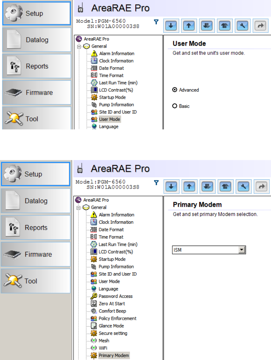
13 User Modes .............................................................................................................................. 63
13.1 Basic User Mode .............................................................................................................. 63
13.2 Advanced User Mode ....................................................................................................... 63
14 Policy Enforcement .................................................................................................................. 63
14.1 Setting Policy Enforcement ............................................................................................... 63
14.2 Deactivating Policy Enforcement....................................................................................... 65
15 Calibration And Testing ............................................................................................................ 67
15.1 Manual Alarms Test ......................................................................................................... 67
15.2 Bump Testing And Calibration .......................................................................................... 67
15.2.1 Bump (Functional) Testing.......................................................................................... 67
15.2.2 Testing The Gamma Radiation Sensor ......................................................................... 69
15.2.3 Zero Calibration For Parts-Per-Billion (ppb) PID Sensor ............................................... 69
15.2.4 Fresh Air Calibration .................................................................................................. 69
15.3 Span Calibration ............................................................................................................... 70
15.4 Three-Point Calibration For Enhanced Linearity With Extended-
Range And ppb PID Sensors.............................................................................................. 70
15.4.1 Enabling 3-Point Calibration Via ProRAE Studio II ...................................................... 72
15.4.2 Multi-Sensor Span Calibration..................................................................................... 73
15.4.3 Single-Sensor Span Calibration ................................................................................... 74
16 Datalog Transfer, Monitor Configuration, and Firmware Upgrades Via Computer ........................ 75
16.1 Downloading Datalogs And Performing PC-Based Instrument
Configuration And Firmware Upgrades.............................................................................. 75
17 Maintenance............................................................................................................................. 76
17.1 Removing/Installing The Rubber Boot ............................................................................... 76
17.2 Replacing The External Filter ............................................................................................ 76
17.3 Removing/Cleaning/Replacing Sensor Modules.................................................................. 77
17.4 Cleaning Or Replacing The PID ........................................................................................ 78
17.4.1 Cleaning Or Replacing The 4R+ PID ........................................................................... 79
17.4.2 Cleaning Or Replacing The 7R+ PID ........................................................................... 81
17.5 Replacing The Sensor Compartment Cover ........................................................................ 86
17.6 Battery Removal/Replacement .......................................................................................... 86
17.7 Alkaline Battery Pack ....................................................................................................... 88
17.8 RAEMet Meteorological Sensor (Optional) ........................................................................ 92
17.9 Antenna Installation .......................................................................................................... 93
17.10 Replacing The Pump......................................................................................................... 94
18 Alarms Overview ..................................................................................................................... 96
18.1 Alarm Signals................................................................................................................... 96
18.2 Changing The Alarm Mode ............................................................................................... 96
19 Diagnostic Mode ...................................................................................................................... 97
19.1 Enter Diagnostic Mode ..................................................................................................... 97
19.2 Adjusting Alarm LEDs & Buzzer ...................................................................................... 97
19.3 Adjusting LCD Contrast.................................................................................................... 97
19.4 Pump Stall Threshold Adjustment...................................................................................... 97
19.4.1 Entering Diagnostic Mode To Set The Pump Stall Threshold......................................... 98
19.4.2 Selecting The Pump Stall Threshold Method ................................................................ 98
19.4.3 Setting Pump Stall Threshold Values – Dynamic Method .............................................. 99
19.4.4 Setting Pump Stall Threshold Values – Static Method ................................................. 101
19.5 Exit Diagnostic Mode ..................................................................................................... 102
AreaRAE Plus & AreaRAE Pro User’s Guide
5
19.6 Alarm Signal Summary ................................................................................................... 103
19.6.1 Hygiene Mode.......................................................................................................... 103
19.6.2 General Alarms ........................................................................................................ 104
20 Troubleshooting ..................................................................................................................... 105
21 Specifications ......................................................................................................................... 106
22 Technical Support................................................................................................................... 122
23 RAE Systems by Honeywell Contacts ...................................................................................... 123
AreaRAE Plus & AreaRAE Pro User’s Guide
6
WARNINGS
Read Before Operating
This manual must be carefully read by all individuals who have or will have the responsibility of using,
maintaining, or servicing this product. The product will perform as designed only if it is used, maintained,
and serviced in accordance with the manufacturer’s instructions.
CAUTION!
Never operate the monitor when the cover is removed. Remove the monitor rear cover or battery only in
an area known to be non-hazardous.
ANY RAPID UP-SCALE READING FOLLOWED BY A DECLINING OR ERRATIC READING
MAY INDICATE A GAS CONCENTRATION BEYOND UPPER SCALE LIMIT, WHICH MAY
BE HAZARDOUS.
TOUTE LECTURE RAPIDE ET POSITIVE, SUIVIE D’UNE BAISSE SUBITE OU ERRATIQUE
DE LA VALEUR, PEUT INDIQUER UNE CONCENTRATION DE GAZ HORS GAMME DE
DÉTECTION QUI PEUT ÊTRE DANGEREUSE
ONLY THE COMBUSTIBLE GAS DETECTION PORTION OF THIS INSTRUMENT HAS
BEEN ASSESSED FOR PERFORMANCE.
UNIQUEMENT, LA PORTION POUR DÉTECTER LES GAZ COMBUSTIBLES DE CET
INSTRUMENT A ÉTÉ ÉVALUÉE.
CAUTION: BEFORE EACH DAY’S USAGE, SENSITIVITY OF THE LEL SENSOR MUST BE
TESTED ON A KNOWN CONCENTRATION OF METHANE GAS EQUIVALENT TO 20 TO 50%
OF FULL-SCALE CONCENTRATION. ACCURACY MUST BE WITHIN 0 AND +20% OF
ACTUAL. ACCURACY MAY BE CORRECTED BY CALIBRATION PROCEDURE.
ATTENTION: AVANT CHAQUE UTILISATION JOURNALIERE, VERIFIER LA SENSIBILITE
DU CAPTEUR DE LIE AVEC UNE CONCENTRATION CONNUE DE METHANE EQUIVALENTE
DE 20 A 50% DE LA PLEINE ECHELLE. LA PRECISION DOIT ETRE COMPRISE ENTRE 0 ET
20% DE LA VALEUR VRAIE ET PEUT ETRE CORRIGEE PAR UNE PROCEDURE
D’ETALONNAGE.
CAUTION: HIGH OFF-SCALE READINGS MAY INDICATE AN EXPLOSIVE
CONCENTRATION.
ATTENTION: DES LECTURES HAUTES ET HORS D’ECHELLE PEUVENT INDIQUER DES
CONCENTRATIONS DE GAZ INFLAMMABLES
CAUTION: SUBSTITUTION OF COMPONENTS MAY IMPAIR INTRINSIC SAFETY.
Note: Users are recommended to refer to ISA-RP12.13, Part II-1987 for general information on
installation, operation, and maintenance of combustible gas detection instruments.
The AreaRAE2 multi-gas detector must be calibrated if it does not pass a bump test, or at least once every
180 days, depending on use and sensor exposure to poisons and contaminants.
AreaRAE Plus & AreaRAE Pro User’s Guide
7
CAUTION!
TheAreaRAE, PGM-65XX shall only be charged using a charger specifically supplied for use
with the unit with a mximum output voltage of 17V.
Use of non-RAE Systems components will void the warranty and can compromise the safe
performance of this product.
MARKING
The PGM-65XX is certified according to the IECEx scheme, ATEX and CSA for US and
Canada under the non-sparking safety method of protection.
The PGM-65XX is marked with the following information:
RAE SYSTEMS
3775 N. 1st. St., San Jose
CA 95134, USA
Type PGM-65XX.
Serial No/barcode: XXXX-XXXX-XX
IECEx XXX15.XXXX
Ex ic nA [ic] IIC T4 Gc
XXX 15 ATEX XXXX
II 3G Ex ic nA [ic] IIC T4 Gc
Cl.I Dv 2, Grps A,B,C,D
T-Code T4.
C22.2 No.152-M1984
ANSI/ISA-12.13.01-2013
-20º C < Tamb < +50º C;
Um:17V
RAEMet connection: Uo: 5.2V, Po: 0.788W, Lo:198uH, Co:1000μF
SSRelay connection: Ui: 24V, Ii: 250mA
Battery pack: W01-3007-000
CAUTION: READ AND UNDERSTAND INSTRUCTION MANUAL BEFORE OPERATING OR SERVICING
ATTENTION: LIRE ET COMPRENDRE MANUEL D’INSTRUCTIONS AVANT D’UTILISER OU SERVICE.
FCC Part 15 Statement
This device complies with Part 15 of the FCC rules. Operation is subject to the following two conditions:
(1) This device may not cause harmful interference, and (2) this device must accept any interference
received, including interference that may cause undesired operation.
AreaRAE Plus & AreaRAE Pro User’s Guide
8
Caution:
This device complies with Part 15 of the FCC Rules / Industry Canada licence-exempt RSS standard(s).
Operation is subject to the following two conditions: (1) this device may not cause harmful interference,
and (2) this device must accept any interference received, including interference that may cause undesired
operation.
Le présent appareil est conforme aux CNR d'Industrie Canada applicables aux appareils radio exempts de
licence. L'exploitation est autorisée aux deux conditions suivantes : (1) l'appareil ne doit pas produire de
brouillage, et (2) l'utilisateur de l'appareil doit accepter tout brouillage radioélectrique subi, même si le
brouillage est susceptible d'en compromettre le fonctionnement.
Changes or modifications not expressly approved by the party responsible for compliance could void the
user's authority to operate the equipment.
This equipment has been tested and found to comply with the limits for a Class B digital device, pursuant
to part 15 of the FCC Rules. These limits are designed to provide reasonable protection against harmful
interference in a residential installation. This equipment generates uses and can radiate radio frequency
energy and, if not installed and used in accordance with the instructions, may cause harmful interference
to radio communications. However, there is no guarantee that interference will not occur in a particular
installation. If this equipment does cause harmful interference to radio or television reception, which can
be determined by turning the equipment off and on, the user is encouraged to try to correct the
interference by one or more of the following
measures:
—Reorient or relocate the receiving antenna.
—Increase the separation between the equipment and receiver.
—Connect the equipment into an outlet on a circuit different from that to which the receiver is connected.
—Consult the dealer or an experienced radio/TV technician for help.
Under Industry Canada regulations, this radio transmitter may only operate using an antenna of a type and
maximum (or lesser) gain approved for the transmitter by Industry Canada. To reduce potential radio
interference to other users, the antenna type and its gain should be so chosen that the equivalent
isotropically radiated power (e.i.r.p.) is not more than that necessary for successful communication.
Conformément à la réglementation d'Industrie Canada, le présent émetteur radio peut fonctionner avec
une antenne d'un type et d'un gain maximal (ou inférieur) approuvé pour l'émetteur par Industrie Canada.
Dans le but de réduire les risques de brouillage radioélectrique à l'intention des autres utilisateurs, il faut
choisir le type d'antenne et son gain de sorte que la puissance isotrope rayonnée équivalente
(p.i.r.e.) ne dépasse pas l'intensité nécessaire à l'établissement d'une communication satisfaisante.
This device complies with Industry Canada’s licence-exempt RSSs. Operation is subject to the following
two conditions:
(1) This device may not cause interference; and
(2) This device must accept any interference, including interference that may cause undesired operation of
the device.

AreaRAE Plus & AreaRAE Pro User’s Guide
9
MPE Reminding
To satisfy FCC / IC RF exposure requirements, a separation distance of 20 cm or more should be
maintained between the antenna of this device and persons during device operation.
To ensure compliance, operation at closer than this distance is not recommended.
Les antennes installées doivent être situées de facon à ce que la population ne puisse
y être exposée à une distance de moin de 20 cm. Installer les antennes de facon à ce
que le personnel ne puisse approcher à 20 cm ou moins de la position centrale de l’
antenne.
La FCC des éltats-unis stipule que cet appareil doit être en tout temps éloigné d’au
moins 20 cm des personnes pendant son functionnement.
Only for detachable antennas:
This radio transmitter (identify the device by certification number, or model number if
Category II) has been approved by Industry Canada to operate with the antenna types
listed below with the maximum permissible gain and required antenna impedance for
each antenna type indicated. Antenna types not included in this list, having a gain
greater than the maximum gain indicated for that type, are strictly prohibited for use
with this device.
MESH
Freewave 900
WIFI
Freewave 2400
Gain of antenna:
3.0dBi
Gain of antenna:
2.0dBi
Gain of antenna:
4.9dBi
Gain of antenna:
2.5dBi Max
Type of
antenna:Omni-
directional
Type of
antenna:Omni-
directional
Type of
antenna:Omni-
directional
Type of
antenna:Omni-
directional
Impedance
d'antenne: 50ohm
impédance
d'antenne: 50ohm
impédance
d'antenne: 50ohm
impédance
d'antenne: 50ohm
Le présent émetteur radio (identifier le dispositif par son numéro de certification ou
son numéro de modèle s'il fait partie du matériel de catégorie I) a été approuvé par
Industrie Canada pour fonctionner avec les types d'antenne énumérés ci-dessous et
ayant un gain admissible maximal et l'impédance requise pour chaque type d'antenne.
Les types d'antenne non inclus dans cette liste, ou dont le gain est supérieur au gain
maximal indiqué, sont strictement interdits pour l'exploitation de l'émetteur.
MESH
Freewave 900
WIFI
Freewave 2400
Gain d'antenne:
3.0dBi
Gain d'antenne:
2.0dBi
Gain d'antenne:
4.9dBi
Gain d'antenne:
2.5dBi Max
Type
d'antenne:Omni-
directional
Type
d'antenne:Omni-
directional
Type
d'antenne:Omni-
directional
Type
d'antenne:Omni-
directional
Impedance
d'antenne: 50ohm
impédance
d'antenne: 50ohm
impédance
d'antenne: 50ohm
impédance
d'antenne: 50ohm
AreaRAE Plus & AreaRAE Pro User’s Guide
10
Operation Area and Conditions
Hazardous Areas classified by Zones
PGM-65XX are intended to be used in hazardous areas classified zone 2 within the temperature range of
-20º C to +50º C, where gases of explosion groups IIA, IIB or IIC and T4 may be present.
Hazardous Areas classified by Divisions
PGM-65XX is intended to be used in hazardous areas classified for Class I Div. 2, within the
temperature range of -20º C to +50º C, where gases of explosion groups A, B, C or D and temperature
code T4 may be present.
INSTRUCTIONS FOR SAFE USE
WARNING: Read and understand instruction manual before operation or servicing.
AVERTISSEMENT: Lisez et comprenez le manual d’instructions avant d’utiliser ou d'effectuer
l'entretien.
WARNING: Substitution of components may impact safety.
AVERTISSEMENT: La substitution de composants peut compromettre la sécurité.
WARNING: To prevent ignition of a hazardous atmosphere, batteries must only be charged in an area
known to be non-hazardous area in the ambient temperature range 0° C ≤ Tamb ≤ 40° C. Use only
approved charger.
AVERTISSEMENT: Afin de prevenir l’inflammation d’atmosphères dangereuse, ne charger le jeu de
batteries que dans des emplacement designés non dangereux a temperature ambiante 0°C ≤ Tamb ≤ 40°C
Utilisez uniquement un chargeur approuvé.
WARNING: As a condition of certification, connection may not be made to the communication port
when the Gas Detector is in the hazardous location unless the area is known not to be hazardous.
AVERTISSEMENT: Comme condition de la certification, un connexion filaire ne peut pas être faite
via le port de communication lorsque le détecteur de gaz est dans la zone dangereuse à moins que la zone
soit connue pour ne pas être dangereuse.
WARNING: Li-Ion rechargeable battery: Only use approved battery pack: W01-3007-000.
AVERTISSEMENT: Batterie rechargeable Li-Ion: Utilisez uniquement des batteries approuvé: W01-
3007-000.
WARNING: For the battery cassette for primary batteries only use 5 new D size alkaline batteries
(Duracell MN1300). Do not mix old and new primary batteries or batteries from different manufacturers,
in the primary battery cassette.
AVERTISSEMENT: Pour la cassette des batteries primaires utilisent seulement 5 nouvelles piles
alcalines de type D (Duracell MN1300). Ne pas mélanger des piles primaires anciennes et nouvelles ou
de différents fabricants, dans la cassette de la batterie primaire.
Only use RAE Systems charger for PGM-65XX with a maximum output voltage of 17V.
AreaRAE Plus & AreaRAE Pro User’s Guide
11
USE IN HAZARDOUS AREAS
Equipment which is intended for use in explosive atmospheres and which has been assessed and certified
according to international regulations may be used only under specified conditions. The components may
not be modified in any way.
The appropriate regulations for service and repair must be properly observed during such activities.
PGM-65XX contains a connector for mounting of a wind sensor – RAEMet. This connector has a set of
entity parameters that mach the input entity parameters of RAEMet:
Uo: 5.2V; Po: 0.788W; Lo: 198μH; Co: 1000μF.
The solid-state relay connection is supplied with following entity parameters, that must be complied with
for external connections: Ui: 24V; Ii: 250mA.
Keep all ports covered when they are not in use. This keeps moisture and debris out of the ports and
contributes to the instrument’s intrinsic safety.
Proper Product Disposal At End Of Life
The Waste Electrical and Electronic Equipment (WEEE) directive (2002/96/EC) is intended
to promote recycling of electrical and electronic equipment and their components at end of
life. This symbol (crossed-out wheeled bin) indicates separate collection of waste electrical
and electronic equipment in the EU countries. This product may contain one or more Nickel-
metal hydride (NiMH), Lithium-ion, or Alkaline batteries. Specific battery information is
given in this user guide. Batteries must be recycled or disposed of properly.
At the end of its life, this product must undergo separate collection and recycling from
general or household waste. Please use the return and collection system available in your
country for the disposal of this product.
Sensor Specifications, Cross-Sensitivities, And Calibration Information
For information on sensor specifications, cross-sensitivities, and calibration information, refer to RAE
Systems Technical Note TN-114: Sensor Specifications And Cross-Sensitivities (available for free
download from www.raesystems.com/downloads/tech-notes). All specifications presented in this
Technical Note reflect the performance of stand-alone sensors. Actual sensor characteristics may vary
when the sensor is installed in different instruments. As sensor performance may change over time,
specifications provided are for brand-new sensors.
Cover all ports when
they are not in use

AreaRAE Plus & AreaRAE Pro User’s Guide
12
1 Features Comparison
The AreaRAE Plus and AreaRAE Plus/Pro share many of the same features and the same
housing. This user’s guide details all features, including those that are only available on the
AreaRAE Plus/Pro (depending your instrument’s configuration it may be configured with a
different number of sensors, different primary radio type, etc.).
The table below shows the features on the AreaRAE Plus and AreaRAE Plus/Pro.
AreaRAE Plus
(PGM-6520)
AreaRAE Plus/Pro
(PGM-6560)
Gas Sensors
Number of Gas
Sensor Slots
7
7
VOC
7R+ 10.6eV Lamp PID (0.1ppm)
4R+ 9.8eV Lamp PID (1ppm)
7R+ 10.6eV Lamp PID (10 ppb)
4R+ 10.6eV Lamp PID (10 ppb)
4R+ 9.8eV Lamp PID (1ppm)
Combustible
LEL
LEL
Toxic EC
Up to 6
Up to 6
Supported Sensors
Liq. O2, CO, CO 2000, CO cw
H2, H2S, H2S ext.,SO2, NO,
NO2, HCN, NH3, PH3, HCl,
HF, ETO-A, ETO-B, ETO-C,
Cl2, ClO2, H2
Liq. O2, CO, CO 2000, CO cw
H2, H2S, H2S ext., SO2, NO,
NO2, HCN, NH3, PH3, HCl,
HF, ETO-A, ETO-B, ETO-C,
Cl2, ClO2, H2
Other Sensors
Gamma
No
Yes (optional)
RAEMet (Wind
Speed, Direction,
Temperature,
Relative Humidity)
Yes (optional)
Yes (optional)
GPS
Yes
Yes
Wireless
Long Range
ISM Band
900/2400 MHz
900/2400 MHz
WiFi
Optional
Optional
Short Range
Mesh
915/868 MHz
915/868 MHz
RF Antenna
Vertical Polarization, Spring
Base
Vertical Polarization, Spring
Base
Solid-State Relays
Yes (3)
Yes (3)
AreaRAE Plus & AreaRAE Pro User’s Guide
13
2 Standard Contents
The AreaRAE Pro and AreaRAE Plus kit includes:
AreaRAE Pro or AreaRAE Plus monitor with sensors, battery, and wireless options as specified
and protective rubber boot installed
USB communication cable
AC/DC power adapter (90-264VAC input) plus power cords
Alkaline battery adapter
3 Spare external filters
Phillips screwdriver
Flathead screwdriver
4R+ PID opening tool (if instrument is equipped with a PID sensor)
7R+ PID cover opening tool (if instrument is equipped with a PID sensor)
PID lamp removal tool (if instrument is equipped with a PID sensor)
Lamp-cleaning kit (isopropanol)
“T”-type calibration tube
QuickStart Guide
CD with documentation
CD with ProRAE Studio II instrument configuration and data management software
Calibration and test certificate
AreaRAE Plus & AreaRAE Pro User’s Guide
14
3 General Information
Honeywell’s AreaRAE Plus/Pro is a wireless, transportable area monitor that can simultaneously detect
toxic and combustible gases, volatile organic chemicals (VOCs), radiation and meteorological factors.
Whether being used into a HazMat response, deploying it at a public venue or installed as part of a fence-
line detection system — for hours, days or weeks at a time — the AreaRAE Plus/Pro gives you the right
hazard intelligence so you can ensure safety for your teams and the general public.
The AreaRAE Plus/Pro also facilitates Industrial Fence-line monitoring and has the capability to trigger
additional devices via relays.
Remote real-time monitoring of sensor data and alarm status is achieved via ProRAE Guardian software.
AreaRAE Plus & AreaRAE Pro User’s Guide
15
3.1 Key Features
Up to seven gas sensors (PID, LEL, Toxics)
Dedicated radiation sensor slot – Gamma sensor
RAEMet station for wind speed and direction, ambient temperature, and relative humidity
Multiple onboard wireless options:
Primary radio: ISM (900/2400 MHz)/WiFi
Secondary radio: Mesh
CID2 certified for U.S., Zone 2 ATEX
Standard GPS module
Relay outputs
On the field interchangeable gas sensor (4R+ Smart sensor)
Colored rubber boots
Battery alkaline adapter
External battery charger
108dB alarm buzzer
Wraparound LED alarm
Easy serviceability (access to pump/ gas sensors/ battery)
Large Screen and intuitive User interface using icon and text (translated)
[N/-] key
[MODE] key
Antenna
Display
Alarm LEDs
Alarm buzzer
(on side)
RAEMet
Meteorological
Sensor
(optional)
Alarm
LEDs
Alarm
LED
[Y/+] key
External filter
And gas inlet
Charging and
USB ports
(on side)
Alarm buzzer
(on side)
AreaRAE Plus & AreaRAE Pro User’s Guide
16
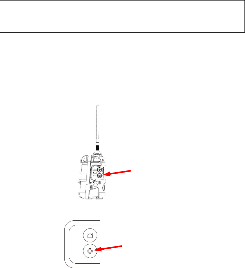
4 Connections
The AreaRAE Plus/Pro has six physical ports located on the left, right, and top sides. The rubber boot
has integral caps for covering the ports when they are not in use.
IMPORTANT!
Keep all ports covered when they are not in use. This keeps moisture and debris out of the ports and
contributes to the instrument’s intrinsic safety.
Cover all ports when
they are not in use
USB for data transfer
DC input for power and
charging the internal battery
Relay connector
Port for future features
RAEMet port
Antenna port
AreaRAE Plus & AreaRAE Pro User’s Guide
17
5 User Interface
The AreaRAE Plus/Pro’s user interface consists of the display, alarm LEDs, an alarm buzzer, and three
keys.
5.1 Display Overview
The LCD display provides visual feedback that includes the sensor types, readings, alarm status, battery
condition, and other information.
5.1.1 Status Indicator Icons
Along the top of most screens are status indicators that tell you whether a function is operating and/or its
strength or level.
Icon
Function
Wireless status: the ISM or WiFi radio is on (blinks when network is not found)
Wireless status: the ISM or WiFi radio is off
ISM or WiFi radio signal 0% to 20%
ISM or WiFi radio signal 21% to 40%
ISM or WiFi radio signal 41% to 80%
ISM or WiFi radio signal 81% to 100%
ISM or
WiFi
Long-haul radio type (ISM or WiFi)
RTR
Number of Mesh Routers connected
STD
Number of standard mesh-radio devices connected
Unit of measure
Reading
Installed, active
sensors
Soft keys
(functions change
by activity)
Status indicators ̶ Datalog, battery
Pump, and “all sensors tested and
calibrated according to policy” tick
mark
Wireless radio on/off
status, signal strength,
active radio types and
number, and GPS status
Heading (changes with alarm, etc.)
Alarm type (High,
Low, etc.)
Temperature
Relative humidity
Wind speed
Wind direction
(relative to 0° north
orientation)
AreaRAE Plus & AreaRAE Pro User’s Guide
18
GPS enabled and power is off
(flashing) Cannot find satellite
1 to 3 satellites
4 to 8 satellites
9 to 12 satellites
Pump operating normally (alternates between these two icons)
Pump blocked (blinks once per second)
Datalogging status (shown when datalogging is on, blank when off)
Battery voltage is ≥80%
Battery voltage is ≥50% and <80%
Battery voltage is ≥10% and <50%
Battery voltage is <10%
Battery error
Sensor due for calibration
Sensor due for a bump test
“All electrochemical sensors tested and calibrated to policy” tick mark (all electrochemical
sensors have been bump tested and calibrated; no sensor is overdue for a bump test or
calibration according to the intervals configured on the instrument). This icon is not shown if
any sensor is due for bump testing or calibration, or if policy enforcement is turned off
Wind speed
Wind direction
Temperature
Relative humidity
AreaRAE Plus & AreaRAE Pro User’s Guide
19
5.1.2 Status Indicator Icons For Instruments Equipped with ISM radio
or WiFi
AreaRAE Plus/Pro instruments equipped with optional ISM radio or WiFi use specific icons to indicate
functionality.
Icon
Description
ISM or WiFi power is off
Cannot find network
Received signal strength is
>0 and <20%
Received signal strength is
≥20% and <40%
Received signal strength is
≥40% and <60%
Received signal strength is
≥60% and <80%
Received signal strength is
≥80%
AreaRAE Plus & AreaRAE Pro User’s Guide
20
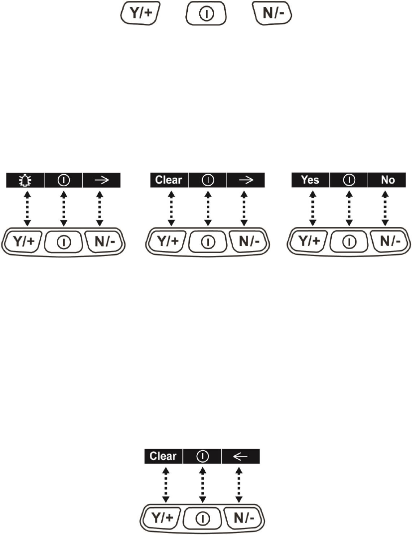
5.2 Keys And Interface
The AreaRAE Plus/Pro has three keys:
Y/+
MODE
N/-
In addition to their labeled functions, [Y/+], [MODE], and [N/-] act as “soft keys” that control different
parameters and make different selections within the instrument’s menus. From menu to menu, each key
controls a different parameter or makes a different selection.
Three panes along the bottom of the display are “mapped” to the keys. These change as menus change,
but at all times the left pane corresponds to the [Y/+] key, the center pane corresponds to the [MODE]
key, and the right pane corresponds to the [N/-] key. Here are examples that show the relationships of the
keys and functions:
In addition to the functions described above, any of the keys can be used to manually activate display
backlighting. Press any key when the backlighting is off to turn it on. A subsequent key press is required
to carry out an actual function corresponding to that key.
5.2.1 Reverse Direction
Sometimes you want to go back to a previous screen rather than advance through an entire set of screens
before “wrapping around” to that screen again.
To reverse direction:
1. Press and hold [N/-] for 3 seconds.
2. When the arrow changes from pointing to the right to pointing to the left, release your finger.
Now when you press [N/-], you step back through the screens.
To change direction again: Press and hold [N/-] for 3 seconds and then release.
Note: Changing direction does not work with all screens. It works primarily in submenus.
AreaRAE Plus & AreaRAE Pro User’s Guide
21
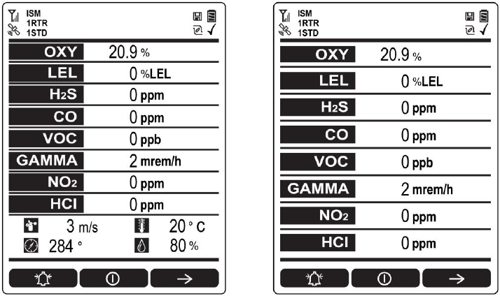
5.3 Screen Display For Various Numbers Of Active Sensors
The AreaRAE Plus/Pro can display readings from one to eight sensors (including dual sensors), plus four
meterology sensors (wind speed, wind direction, temperature, relative humidity) depending on the AreaRAE
Plus/Pro’s configuration. In order to maximize readability and the amount of information shown, the display is
automatically reconfigured, according to the number and types of sensors in the AreaRAE Plus/Pro.
8 Sensors with meteorology sensors
8 sensors without meteorology sensors
5.4 Glance Mode
Glance Mode allows you to get vital information without turning on the AreaRAE Plus/Pro. You can
check information such as the instrument’s model and serial number, installed sensor types, wireless
modules installed, etc., which may help when taking inventory of instruments and their sensors or when
working with service or support personnel. Glance Mode can be enabled/disabled via ProRAE Studio II.
5.4.1 Enter Glance Mode
Note: The instrument must be configured so that Glance Mode is turned on (the default mode is “Off”).
This can be done in ProRAE Studio II.
With the AreaRAE Plus/Pro turned off, press and hold [Y/+] to enter Glance Mode. The feature is
latched, meaning that it runs even after you release the [Y/+] key. If you see the message “GLANCE
DISABLED,” you must configure the instrument to use Glance Mode.
If Glance Mode is enabled, the first screen is displayed. After releasing [Y/+], other screens can be
displayed by pressing the [N/-] Key. In ProRAE Studio II, Glance Mode can be enabled or disabled by
checking or unchecking the box labeled “Enable Glance Mode.”
5.4.2 Screens
Every screen displayed in sequence as configuration. Press [N/-] to advance to the next screen.
Press [MODE] to exit Glance Mode. The screens are shown in sequence.
5.4.3 Exit Glance Mode
The AreaRAE Plus/Pro exits Glance Mode and turns off when you press the [MODE] key. In addition, if
you do not press either key in 60 seconds, the AreaRAE Plus/Pro automatically exits Glance Mode.
AreaRAE Plus & AreaRAE Pro User’s Guide
22
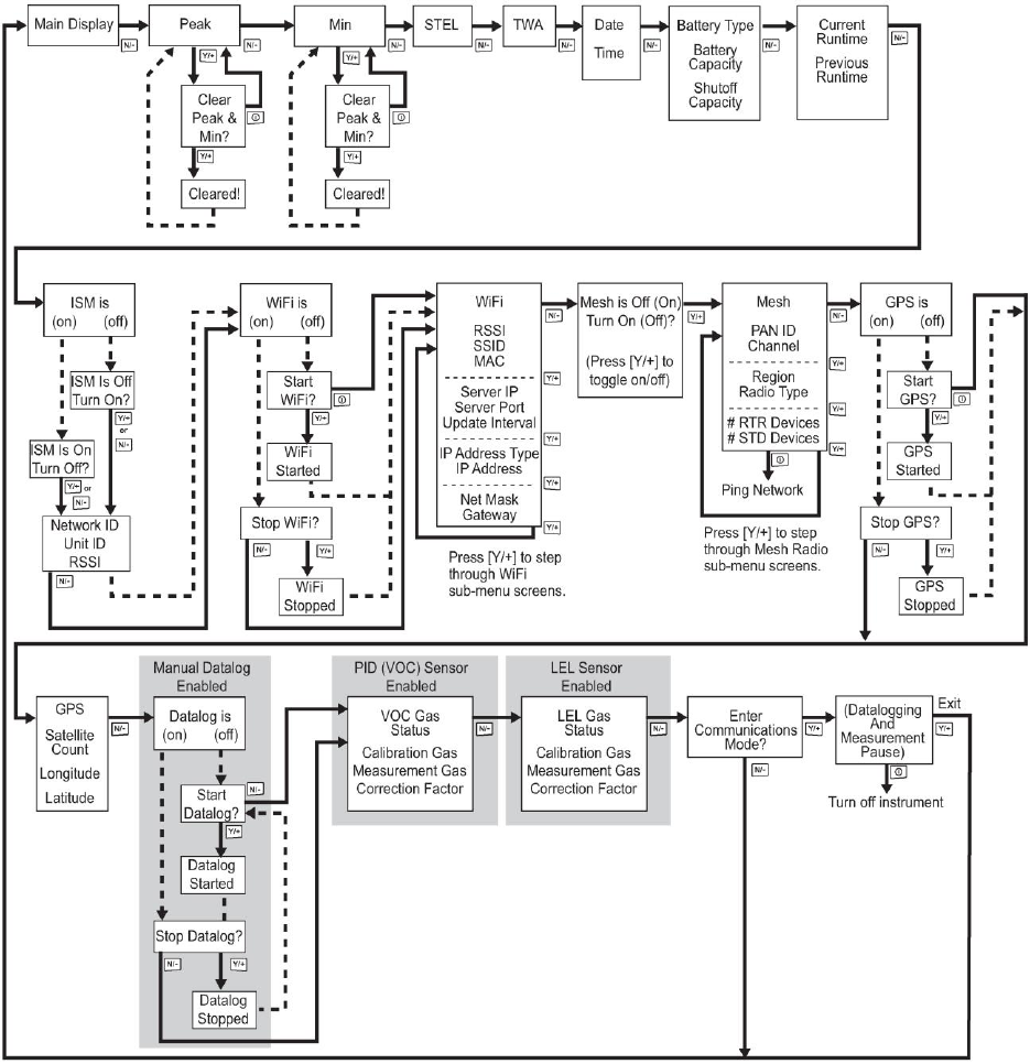
5.5 Menus
The reading menus are easy to step through by pressing the [N/-] key.
Notes:
If the instrument is not equipped with a VOC sensor (PID), or is not equipped with an LEL sensor,
then screens for those sensors (VOC Gas Status and LEL Gas Status, respectively) are not shown.
If ISM or WiFi is not the primary modem, its menu is not displayed.
5.5.1 Operation Mode Navigation
Note: Dashed line indicates automatic progression.
AreaRAE Plus & AreaRAE Pro User’s Guide
23
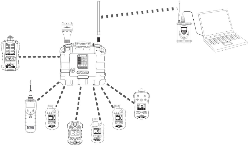
6 Wireless Operation
Depending on the wireless configuration of the instrument and which radio modules are active, the
AreaRAE Plus/Pro can communicate directly through ISM-band radio to a RAELink3 wireless Host
modem (located up to 2 miles/3.2km away) or via WiFi to a WiFi access point. In addition, the AreaRAE
Plus/Pro is equipped with a Mesh-radio modem that communicates with Mesh-equipped instruments such
as the MultiRAE, ToxiRAE Pro, etc., located up to 330 feet (100 meters) away. Up to eight of these
instruments’ data can be relayed through the AreaRAE Plus/Pro to a PC running ProRAE Guardian to
monitor them, as well as the AreaRAE Plus/Pro.
Note: If the AreaRAE Pro or AreaRAE Plus is equipped with WiFi, and Wifi is used as the primary radio
instead of ISM, then a WiFi access point substitutes for the RAELink3 Host.
RAELink3
Host
PC running
ProRAE
Guardian
AreaRAE Plus/Pro
acts as access
point and relays data
from connected
wireless instruments
MiniRAE 3000, QRAE 3, ToxiRAE
Pros, and MicroRAE connected via
Mesh radio to AreaRAE Plus/Pro
MultiRAE
connected via
Mesh radio to
AreaRAE Plus/Pro
ISM
AreaRAE Plus & AreaRAE Pro User’s Guide
24
7 Wireless Control And Submenus
When you step through the main menu, as shown in the previous diagram, there are screens for wireless
communication, including ISM, WiFi, and Mesh radio.
In order to allow turning radios on or off in the AreaRAE Plus/Pro, you can use ProRAE Studio II to set the
instrument in Advanced User Mode or Basic User Mode.
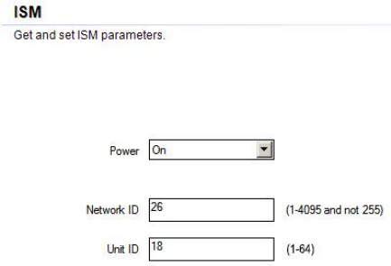
It is also necessary to select a Primary Modem if the AreaRAE Plus/Pro is equipped with both ISM and WiFi
modems.
AreaRAE Plus & AreaRAE Pro User’s Guide
25
7.1 ISM Settings
Every network using ISM radio must have a Network ID, which identifies that network and all
equipment operating in that network. All AreaRAE Plus/Pro and RAELink3 (or other RAELink
model) Host, Repeater, and Remote wireless modems in the same AreaRAE network need to be
configured with the same Network ID. Each device on the network must have a unique Unit ID.
Note: ISM Settings can be adjusted in the AreaRAE Plus/Pro’s Wireless menu under “ISM.”
AreaRAE Plus & AreaRAE Pro User’s Guide
26
8 WiFi Settings
AreaRAE Plus/Pro’s WiFi is designed to operate on a wireless network anchored by ProRAE Guardian
monitoring software and using WiFi access points. Operational distance between the instrument and the
access point (wireless router) varies, depending on distance, interference, and obstacles. It uses the
802.11b protocol using the 2.4GHz ISM (license-free) frequency band.
Note: To ensure the best communication, it is recommended that the WiFi-equipped instruments and
access point not be located close to microwave ovens, cordless telephones, or Bluetooth devices.
8.1 Setting WiFi Communication Parameters In ProRAE Studio II
WiFi-equipped instruments’ parameters for communication must be set in ProRAE Studio II.
1. Connect WiFi-equipped instrument via USB to a PC running ProRAE Studio II.
2. Place the AreaRAE Plus/Pro in Communications Mode.
3. From the main screen, press [N/-] until you see “Enter Communications Mode?”
4. Press [Y/+].
5. Select PC.
The message on the display should say “Ready To Communicate With Computer”.
1. Start ProRAE Studio II.
2. Log in using your Administrator’s password.
3. Click the “Detect Instruments Automatically” icon.
4. When your WiFi-equipped instrument is detected, click on its information and then click
“Select”.
AreaRAE Plus & AreaRAE Pro User’s Guide
27
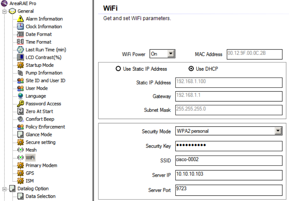
5. Click “Setup” to download the current settings from the WiFi-equipped instrument. The main
screen appears.
6. Find and click “WiFi” in the list.
WiFi parameters appear in the right pane.
You can now change settings for the WiFi-equipped instrument. When you are done, click this icon to
send the new settings to the instrument:
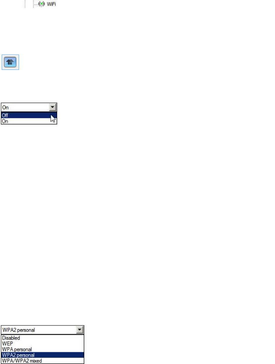
8.1.1 WiFi Power
Select either “On” or “Off” to set the default power setting for your WiFi-equipped instrument.
Note: WiFi Power can also be turned on or off in the AreaRAE Plus/Pro in the Wireless menu’s “WiFi.”
8.1.2 Address
Select “Use Static IP Address” if you have a static IP or “Use DHCP” if your system allows dynamic
hosting configuration. Check with your system administrator to determine which is appropriate for your
network.
If you use a static IP address, you must provide the Static IP address, Gateway, and Subnet Mask. If you
are using DHCP, you do not have to provide these, because they will be filled in automatically.
8.1.3 Channels And Security
Check with your system administrator for the settings in this section.
8.1.4 Security Mode
Different types of wireless security guard your network against possible instances of unauthorized
access. Using security, you can:
Ensure that no one can easily connect to your wireless network without permission
Personalize access regarding who can configure your wireless settings
Protect all data that is transmitted through the wireless network
Check with your system administrator for the wireless security mode you should use.
Use the drop-down menu to select the type of security:

AreaRAE Plus & AreaRAE Pro User’s Guide
28
Then set your Security Key.
8.1.5 Security Key
Depending on the type of security you choose, your key will have to be a different number of characters.
Here are characteristics of the different types, their relative security strength, and the number of
characters needed in the key:
Security Type
Security Rank
Number of Characters
WEP (Wired Equivalent Protocol)
Basic
40/64-bit (10 characters)
128-bit (26 characters)
WPA Personal
Wi-Fi Protected Access Personal
Strong
8 to 63 characters
WPA2 Personal
Wi-Fi Protected Access 2 Personal
Strongest
8 to 63 characters
WPA2/WPA Mixed Mode
WPA2: Strongest
WPA: Strong
8 to 63 characters
Warning! Using a network with security disabled is not recommended.
8.1.6 SSID
The SSID (Service Set Identifier) is a case-sensitive unique identifier attached to the header of packets
sent over a wireless local-area network. Each wireless network in your range will have its own SSID.
Consult with your IT department for the SSID.
8.1.7 Server IP
This is the destination IP address for the instrument to communicate with a computer running ProRAE
Guardian
8.1.8 Server Port
The port number is distinct from any physical port on a computer such as a COM port or an I/O port
address. It is a 16-bit address that exists only for the purpose of passing certain types of information to the
correct location above the transport layer of the protocol stack.
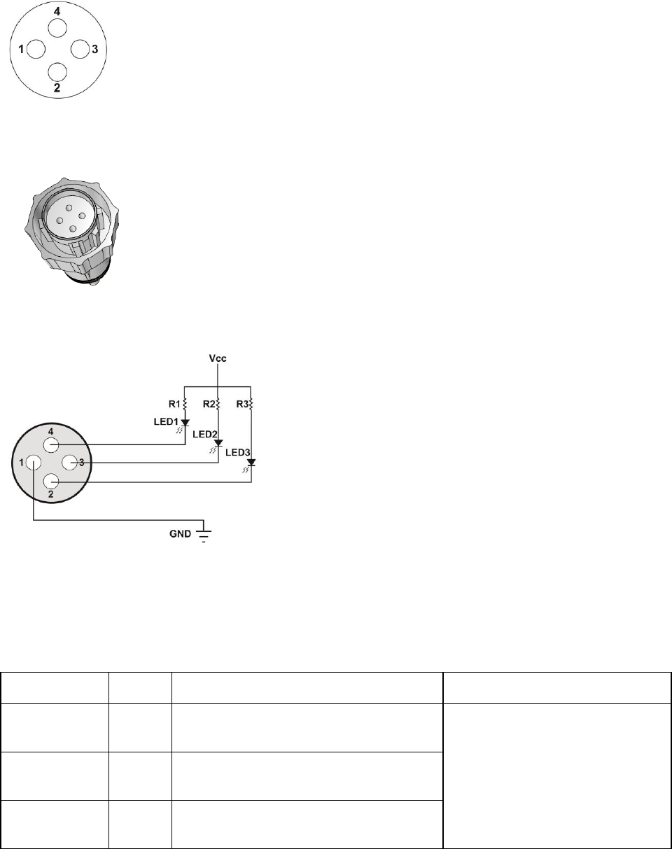
9 Relays For Controlling External Equipment
The AreaRAE Pro/Plus is equipped with three solid-state relays that are switched by gas sensor alarm
conditions. These relays are always active. The relays’ contacts are protected against high in-rush current.
They can be tested by accessing Diagnostic Mode.
Status: Normally Closed (default)
Type: Dry Contact
Maximum voltage: 24VDC
Maximum amperage: 250mA
Relays open to indicate High, Low, and Sensor Failure status.
Note: If an external device is not connected, keep the dust cap on the connector to protect the pins.
AreaRAE Plus & AreaRAE Pro User’s Guide
29
Pinout For Relay Port:
Pin1: COM (GND)
Pin2: Relay1 output
Pin3: Relay2 output
Pin4: Relay3 output
A mating connector for wiring to external devices is available from electronics distributors:
Samtec part number ACP-16-03-G-00.30-S-BC-O-1
Test Setup For Relays:
The output from the three potential-free relay connections for intrinsic safety (IS ic) circuits is:
Ui=24
Ii=250mA
Relay Alarm Indications
Relay number
Alarm
Description
AreaRAE Pro/Plus Display
1
Low
Instant reading reaches the low limitation
of any sensor installed
The text “Low,” “High,” “Fail,”
“Lamp,” and “Over” flashes
alongside the readings.
2
High
Instant reading reaches the high
limitation of any sensor installed
3
Fail
Any sensor in Fail alarm, VOC sensor in
Lamp alarm, LEL sensor in Over alarm.
AreaRAE Plus & AreaRAE Pro User’s Guide
30
10 Battery
Always make sure the battery is fully charged before using the AreaRAE Plus/Pro. Two battery options
are available for the AreaRAE Plus/Pro (PGM-65XX):
1. Standard duration rechargeable Li-ion battery (PN: W01-3007-000)
2. Alkaline battery pack for five standard D-sized batteries (PN: W01-3007-300)
WARNING
To reduce the risk of ignition of hazardous atmospheres, recharge, remove or replace the battery
only in an area known to be non-hazardous! Do not mix old and new batteries or batteries from
different manufacturers.
10.1 Charging
Note: Batteries should be charged in an environment where the temperature is in the range of 32° to 104°
F (0° to 40° C).
Follow this procedure to charge the AreaRAE Plus/Pro:
1. Remove the cover over the AreaRAE Plus/Pro’s power port.
2. Plug the AC/DC adapter’s barrel plug into the AreaRAE Plus/Pro’s power port.
3. Plug the AC/DC adapter into the wall outlet.
The AreaRAE Plus/Pro begins charging automatically. The display shows that the battery is charging.
Green LEDs around the top of the AreaRAE Plus/Pro are used in Charge mode and Diagnostic mode.
AreaRAE Plus & AreaRAE Pro User’s Guide
31
Charging without a VOC sensor installed: After the battery is fully charged, the green LEDs flash once
every 10 seconds.
Charging with a VOC sensor installed: The AreaRAEPro performs a VOC sensor auto-cleaning for
two hours, and then it runs the pump for 20 minutes. The large battery icon is shown on the screen while
auto cleaning is taking place. After auto cleaning is completed and the battery is fully charged, the green
LEDs flash once every 10 seconds.
Note: The AreaRAE Plus/Pro does not charge alkaline batteries in the alkaline battery pack.
IMPORTANT!
Always securely close the cover over the power port when not charging. This keeps moisture and debris
out of the port.
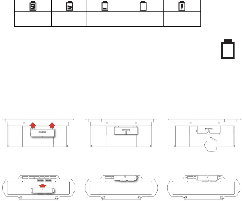
10.2 Battery States
The battery icon on the display shows how much charge is in the battery and alerts you to any charging
problems.
Full charge
2/3 charge
1/3 charge
Low charge
Battery
alert
When the battery’s charge falls below a preset voltage, the instrument warns you by beeping
once and flashing once every minute, and the “empty battery” icon blinks on and off once per
second. The instrument automatically powers down within 15 minutes, after which you will
need to either recharge the battery, or replace it with a fresh one with a full charge.
10.3 External Battery Charger
You can charge a spare Li-Ion battery with the optional External Li-Ion Battery Charger For AreaRAE
(P/N: W01-3005-000).
Align the Charger’s
edges and contact pins
with the battery
Top View
Rear View
Press the Charger into
place, making sure the
contact pins mate
Press down on the back
of the Charger to ensure
that it is securely set
AreaRAE Plus & AreaRAE Pro User’s Guide
32
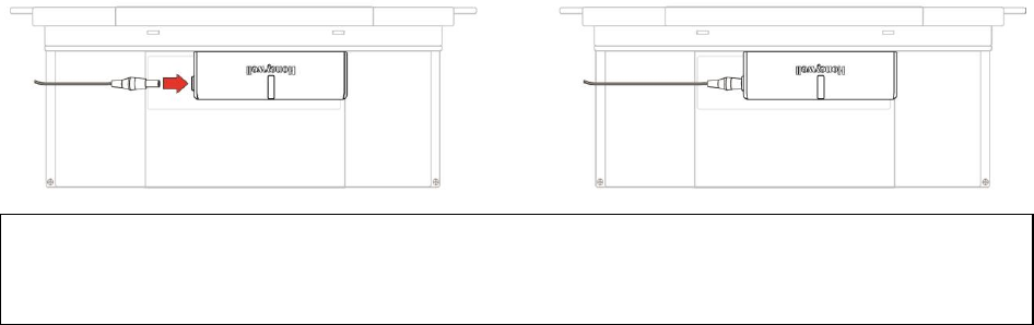
Once the Charger is attached to the battery, plug in the AC adapter’s barrel and the plug the power cord
into an AC source.
WARNING
To reduce the risk of ignition of hazardous atmospheres, recharge, remove or replace the battery
only in an area known to be non-hazardous!
AreaRAE Plus & AreaRAE Pro User’s Guide
33
11 Turning The AreaRAE Plus/Pro On And Off
11.1 Turning The AreaRAE Plus/Pro On
With the instrument turned off, press and hold the [MODE] key until the beep sounds and the display and
LED alarm lights turn on. Then release the [MODE] key.
A RAE Systems logo (or a company name) should appear first. This is followed by a progression of
screens that tell you the AreaRAE Plus/Pro’s current settings.
11.1.1 Pausing To View Screens During Startup
Press the [MODE] button anytime during the startup sequence to pause the progression. This allows you
to view the information for as long as you like. To resume the progression, press [MODE] again. Even if
you pause the progression of screens, the startup process is not interrupted.
Note: To speed up the startup time, the number of screens shown on startup can be reduced by enabling
the Fast Startup option under Programming/Monitor.
Then the AreaRAE Plus/Pro’s main reading screen appears. It displays instantaneous readings similar to
the following screen (depending on the sensors installed) and is ready for use.
Note: If the battery is completely empty, then the display briefly shows the message “Battery Low,” and
the AreaRAE Plus/Pro shuts off. You should charge the battery or replace it with a fully charged battery
before turning it on again.
11.2 Turning The AreaRAE Plus/Pro Off
Press and hold [MODE]. A 5-second countdown to shutoff begins. You must hold your finger on the key
for the entire shutoff process until the AreaRAE Plus/Pro is powered off.

AreaRAE Plus & AreaRAE Pro User’s Guide
34
11.3 Testing Alarm Indicators
Under normal-operation mode and non-alarm conditions, the buzzer, LEDs, and backlight can be tested at
any time by pressing [Y/+] once.
IMPORTANT!
If any of the alarms does not respond to this test, check the Alarm Settings in Programming Mode. It is
possible that any or all of the alarms have been turned off. If all of the alarms are turned on, but one or
more of them (buzzer or LED lights) does not respond to this test, do not use the instrument. Contact your
RAE Systems distributor for technical support.
11.4 Pump Status
IMPORTANT!
During operation, make sure the probe inlet and the gas outlet are free of obstructions. Obstructions can
cause premature wear on the pump, false readings, or pump stalling. During normal operation, the pump
icon alternately shows inflow and outflow as shown here:
If there is a pump failure or obstruction that disrupts the pump, the alarm sounds and you see this icon
blinking on and off:
Once the obstruction is removed, you can try to restart the pump by pressing the [Y/+]. If the pump does
not restart, and the pump stall alarm continues, consult the Troubleshooting section of this guide or
contact RAE Systems Technical Support.
It is advisable to perform a pump stall test periodically, to make sure the pump is working properly and
there are no leaks in the system. To perform a pump stall test, simply block the gas inlet with your finger.
To pass the test, the instrument should go into a pump alarm. Press [Y/+] to disable the alarm and return
to normal operation.
Note: For all AreaRAE Plus/Pro instruments with a 4R+ PID, if the pump is in alarm for more than five
minutes, the PID lamp automatically turns off. The display reading shows “- - -” and there is a “Lamp”
alarm. Click [Y/+] to restart the pump. If there is no longer a pump alarm, then the PID lamp will require
a 2-minute warm-up to stabilize. During this time, the PID’s reading shows “- - -”. Once the PID lamp is
warmed up, the display shows the actual value.
11.5 Calibration Status
The instrument displays this icon next to the sensor that requires calibration:
Calibration is required (and indicated by this icon) if:
The lamp type has been changed.
The sensor module has been replaced with one whose calibration is overdue.
The defined period of time between calibrations has been exceeded.
If you have changed the calibration gas type without recalibrating the instrument.
The sensor has failed a previous calibration.

AreaRAE Plus & AreaRAE Pro User’s Guide
35
11.6 Bump Status
The instrument displays this icon next to the sensor that requires bump test:
A bump test is required (and indicated by this icon) if:
The defined period of time between bump tests has been exceeded (bump test overdue).
The sensor has failed a previous bump test.
The sensor(s) should be challenged on a periodic basis.
AreaRAE Plus & AreaRAE Pro User’s Guide
36
12 Programming
The menu in Programming Mode is to adjust settings, and calibrate sensors. It has the following
submenus:
Measurement
Alarms
Datalog
Wireless
Monitor
Calibration
12.1 Enter Programming In Basic Mode
Programming in Basic Mode is limited to calibration only. A password is required to access other
programming menus.
1. To enter Programming Mode, press and hold [MODE] and [N/-] until you see the Password screen.
2. Input the 4-digit password:
Increase the number from 0 through 9 by pressing [Y/+].
Step from digit to digit using [N/-].
Press [MODE] when you are done.
If you make a mistake, you can cycle through the digits by pressing [N/-] and then using [Y/+] to change
the number in each position.
Note: The default password is 0000.
Note: The password screen appears when you enter the Programming Mode the first time after turning the
instrument on in Basic Mode, and each time after that.
AreaRAE Plus & AreaRAE Pro User’s Guide
37
Once you enter Programming Mode, the Calibration menu is highlighted. You cannot access other menu
items, and you can only perform the following types of calibration:
Fresh Air
Multi Sensor Span
Single Sensor Zero
Single Sensor Span
The following require password access in Basic Mode or can be directly accessed in Advanced
Mode.
Multi Sensor Bump
Single Sensor Bump
Cal. Reference
Change Cal. Gas
Multi Cal Select
Change Span Value
To enter a menu and view or edit parameters in its submenus, press [Y/+].
12.2 Enter Programming In Advanced Mode
1. To enter Programming Mode, press and hold [MODE] and [N/-] until you see the Calibration screen.
No password is necessary in Advanced Mode.
2. Press [N/-] to step through the programming screens.
Note: Holding down [N/-] advances quickly through the menu options.
When a menu item is selected, its name is shown at the top of the screen, and its icon is enlarged.
To enter a menu and view or edit parameters in its submenus, press [Y/+].
AreaRAE Plus & AreaRAE Pro User’s Guide
38
12.3 Menus And Submenus
In Programming Mode, menus and submenus are organized as shown here:
Measurement
Alarms
Datalog
Wireless
Monitor
Calibration
Sensor On/Off
Alarm Limits
Clear Datalog
Sel Primary
Radio
LCD Contrast
Fresh Air
Change Meas.
Gas
Alarm Mode
Datalog
Interval
GPS
Pump Speed
Multi Sensor
Span
Measurement
Unit
Alarm
Settings
Sensor
Selection
Mesh
Zero At Start
Single Sensor
Zero
Duplicated
Sensor
Comfort Beep
Data Selection
ISM
Fast Startup
Single Sensor
Span
Datalog Type
WiFi
Language
Multi Sensor
Bump
Memory Full
Action
Site ID
Single Sensor
Bump
User ID
Cal. Reference
Secure In
Place
Change Cal.
Gas
Multi Cal.
Select
Change Span
Value
12.3.1 Editing And Selecting Parameters And Sensors
There are a few basic ways to edit parameters, select sensors, and perform other activities in the
AreaRAE Plus/Pro. The actions performed by pressing keys always match 1-to-1 with the boxes
along the bottom of the display and the three keys. Some parameters are edited by scrolling and
selecting individual items (black bars behind white text act as highlighters). Some include a
choice via “radio buttons,” where only one item in a list can be selected, while other menus use
boxes for you to “check” with an “X,” and these allow for multiple items in a list to be selected.
In all cases of editing, you can save or undo your choice.
AreaRAE Plus & AreaRAE Pro User’s Guide
39
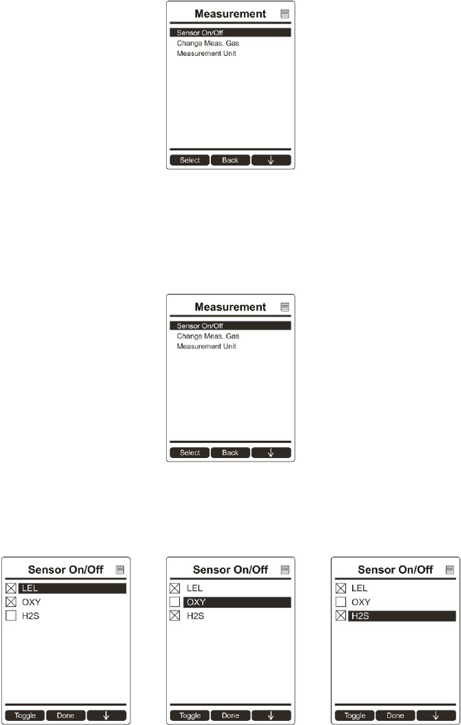
12.3.2 Measurement
The submenus for Measurement include Sensor On/Off, Change Measurement Gas, and VOC and
Gamma (if equipped) Measurement Units.
Sensor On/Off
You can turn sensors on or off via this submenu. An “X” in a box to the left of a sensor’s name indicates
it is turned on.
1. Scroll down the list of sensors using the [N/-] key.
2. Add or remove that gas from the list by pressing [Y/+]. An “X” in a box to the left of a sensor’s
name indicates it is selected.
3. Once you have made all your selections, press [MODE] for “Done.”
AreaRAE Plus & AreaRAE Pro User’s Guide
40
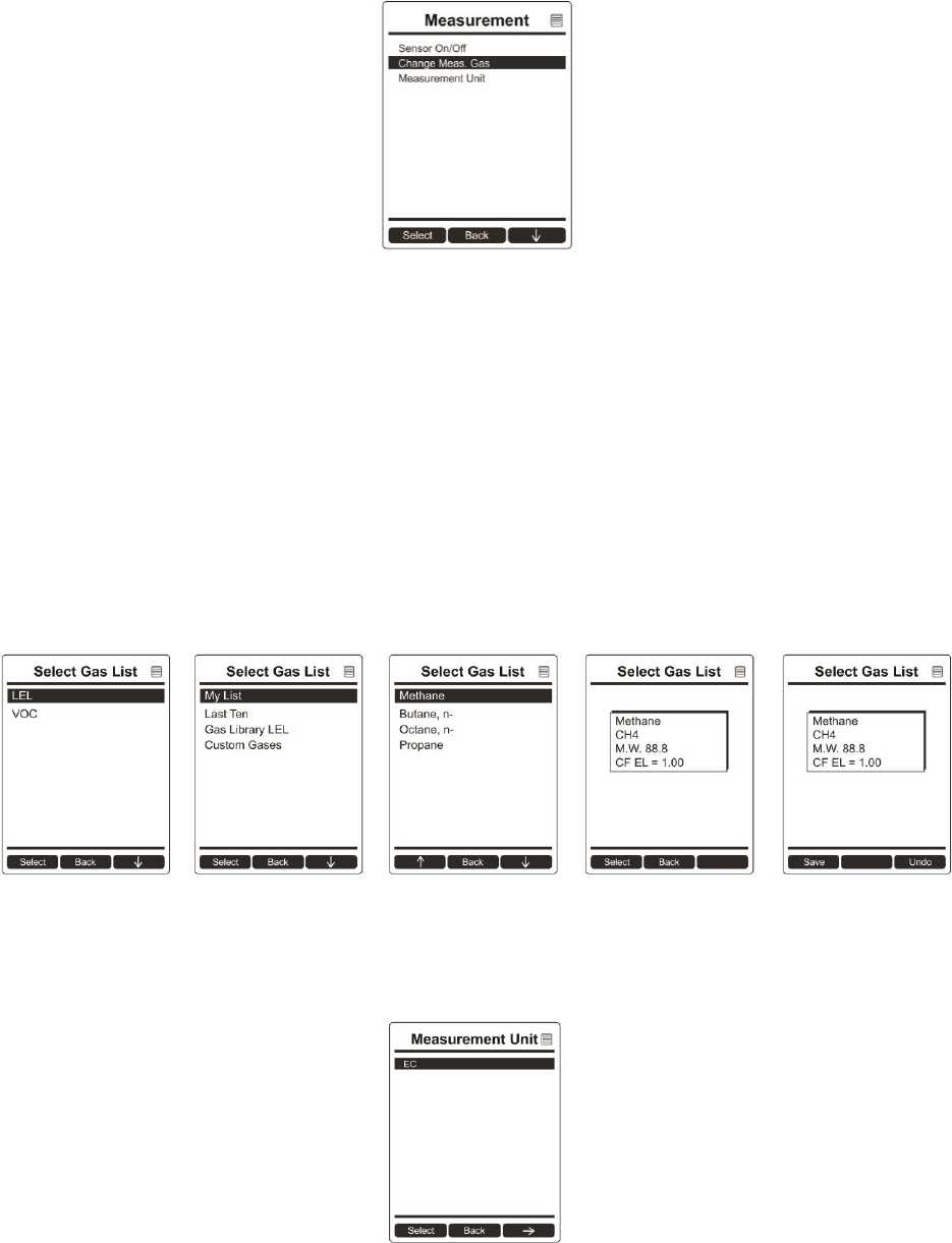
Change Meas. Gas
The AreaRAE Plus/Pro has extensive onboard gas libraries for combustible gases and VOCs that you can
use to configure your AreaRAE Plus/Pro to automatically apply the appropriate correction factors and
produce readings in the units of the desired combustible gas or VOC.
Measurement gases are organized in four lists:
My List is a customized list of gases that you create. It contains a maximum of 10 gases and can only
be built in ProRAE Studio II on a PC and transferred to the instrument.
Note: The first gas in the list is always isobutylene (it cannot be removed from the list).
Last Ten is a list of the last ten gases used by your instrument. The list is built automatically and is
only updated if the gas selected from Custom Gases or Library is not already in the Last Ten. This
ensures that there is no repetition.
Gas Library is a library that consists of more than 200 gases for the PID sensor and more than 50 for
the catalytic LEL sensor.
Custom Gases are gases with user-modified parameters. Using ProRAE Studio II, all parameters
defining a gas can be modified, including the name, span value(s), correction factor, and default alarm
limits.
Measurement Unit
In some cases, the measurement unit for displaying data from sensors can be changed. The type of sensor
is shown in the display, and if there is more than one sensor type (VOC, EC, Gamma), they are shown in
a list.
AreaRAE Plus & AreaRAE Pro User’s Guide
41
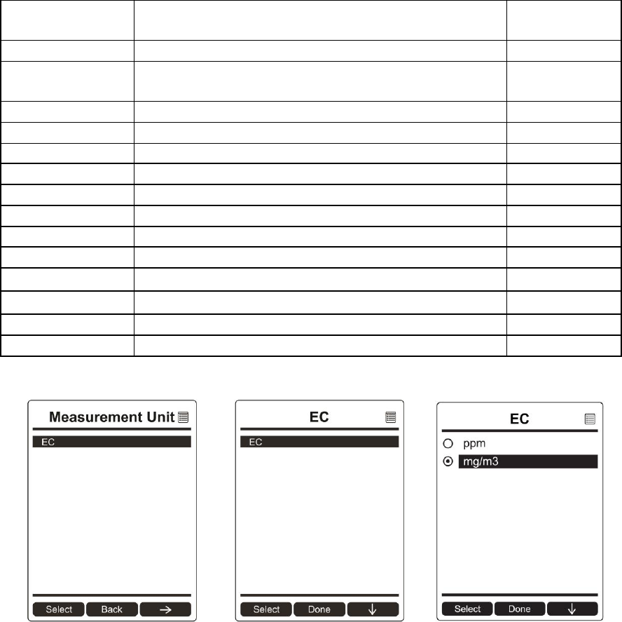
Depending on the installed sensors, standard available measurement units include:
Abbreviation
Unit
Sensor
Type
ppm,ppb
parts per million, parts per billion
PID for VOC
mg/m3, ug/m3
milligrams per cubic meter, micrograms per cubic
meter
PID for VOC
ppm
parts per million
EC
mg/m3
milligrams per cubic meter
EC
μrem/h, mrem/h
microrems and millirems per hour
Gamma
μSv/h, mSv/h
microSieverts and milliSieverts per hour
Gamma
μR/h, mR/h
microRoentgens and milliRoentgens per hour
Gamma
μGy/h, mGy/h
microGrays and milliGrays per hour
Gamma
ppm
parts per million
CO2
VOL
Volume
CO2
ºF
Fahrenheit degrees
Temperature
ºC
Celsius degrees
Temperature
m/s
meter per second
Wind speed
MPH
mile per hour
Wind speed
Here is an example of the menu hierarchy (select the sensor type and then the measurement unit):
Duplicated Sensor
If there is sensor duplication (for example, two PID sensors for VOC), then the “Duplicated Sensor”
menu item is shown. You can select which of the duplicated sensors to make active. The instrument does
not support duplicate sensors.

AreaRAE Plus & AreaRAE Pro User’s Guide
42
12.3.3 Alarms
Use this menu to change high, low, STEL, and TWA alarm limits - the points at which alarms are
triggered. The Alarms menu also allows changing alarm mode (latched or automatic reset) and alarm
output methods (combinations of light and buzzer alarm indications).
Alarm Limits
There are four groups of alarm settings that you can adjust for each individual sensor for which a
particular alarm type is available.
Settings:
High Alarm
Low Alarm
STEL (Short-Term Exposure Limit) Alarm
TWA (Time-Weighted Average) Alarm
Note: Some alarm settings are not applicable to all sensors. If a setting is irrelevant to a sensor (for
example, STEL for a gamma radiation sensor), then that sensor does not appear in the list.
Alarm Mode
You can program the AreaRAE Plus/Pro so that there are two ways to shut off an alarm:
Auto Reset
When the alarm condition is no longer present, the alarm stops automatically.
Latch
You must manually turn off an alarm when one is triggered. The latched setting
only controls alarms for High Alarm, Low Alarm, STEL Alarm, and TWA Alarm.
Alarm Settings
You can enable/disable any combination of light (visible) or buzzer (audible) alarms, or alarms off.
Settings:
All Enabled
Light
Buzzer
All Disabled
Comfort Beep
A Comfort Beep is a single beep of the audible alarm at 60-second intervals that informs the person using
the AreaRAE Plus/Pro that it is functioning. It can be turned on or off.
AreaRAE Plus & AreaRAE Pro User’s Guide
43
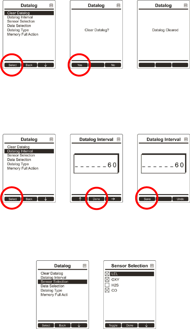
12.3.4 Datalog
The instrument displays a floppy disk icon to indicate that a datalog is being recorded. The instrument
stores the measured gas concentration for each sensor, date and time for each measurement, Site ID, User
ID, and other parameters. The AreaRAE Plus/Pro memory is sufficient to record six months’ worth of
data for 12 sensors and GPS at one-minute intervals, 24/7. All data are retained (even after the unit is
turned off) in non-volatile memory so that they can be downloaded at a later time to a PC.
Clear Datalog
This operation erases all data stored in the datalog. Select “Clear Datalog,” and then “Yes.”
Note: Once the datalog is cleared, the data cannot be recovered.
Datalog Interval
Intervals are shown in seconds. The default value is 60 seconds. The maximum interval is 3600 seconds,
and the minimum is 1 second.
Sensor Selection
You can choose which sensors’ data are included in the datalog. The entire list of installed sensors is
shown, and you can individually select whether their data is included.
AreaRAE Plus & AreaRAE Pro User’s Guide
44
Note: Turning a sensor off in the list does not change or erase its settings.
Data Selection
Data Selection allows you to select which types of data are stored and made available when you
download your datalog to a computer via ProRAE Studio II (version 1.04 or higher) software.
You can choose any or all of four types of data (you must choose at least one):
Minimum
Average
Maximum
Real-Time
Datalog Type
The instrument offers three options for starting the datalogging process:
Auto Automatically collects datalog information every time the instrument is sampling until
the datalog memory is full.
Manual Datalogging occurs only when you manually initiate it (see below for details).
Note: You can only choose one datalog type to be active at a time.
About Manual Datalogging
When the instrument is set to Manual Datalog, you can turn datalogging on and off by repeatedly pressing
[N/-] and stepping through the screens from the main display until you reach the screen that says “Start
Datalog?”
When you reach the screen that says “Start Datalog?” press [Y/+] to start it. You see “Datalog
Started,” confirming that datalogging is now on. You can turn it off by pressing [Y/+] again.
If datalogging is running, you can leave it running. However, if you want to turn it off, follow this
procedure:
AreaRAE Plus & AreaRAE Pro User’s Guide
45
Press [N/-] repeatedly to step through the screens until you reach the screen that says, “Stop
Datalog?” Press [Y/+] to stop datalogging. The screen displays “Datalog Stopped” for a few
seconds, before displaying “Start Datalog?” and the datalog interval. You can restart it
anytime by pressing [Y/+] from that screen.
Memory Full Action
When the internal datalog memory is full, the AreaRAE Plus/Pro can either stop collecting data (Stop
When Full) or go back to the beginning and overwrite the data from the first entry, second entry, etc.
(Wraparound).
AreaRAE Plus & AreaRAE Pro User’s Guide
46
12.3.5 Wireless
When an AreaRAE Plus/Pro is equipped with a wireless modem, its settings are controlled via the menu
items under “Wireless.”
Note: Instruments equipped with WiFi provide different menu choices. Refer to page 26 for details.
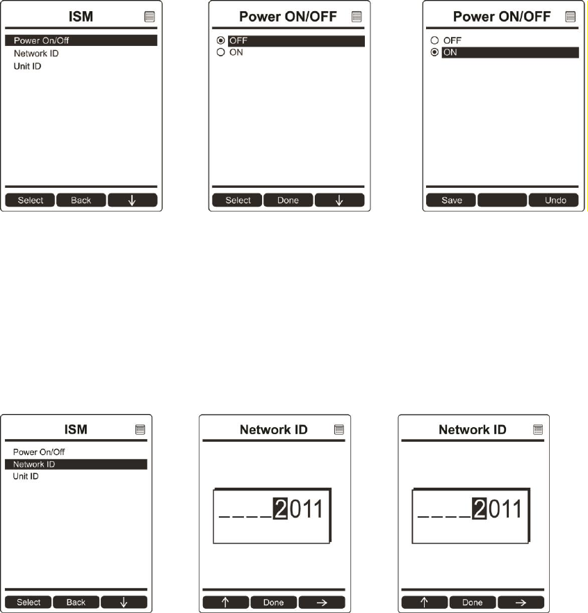
Select Primary Radio
Select the primary radio.
1. Choose between “ISM” and “WiFi” by pressing [N/-].
2. Select the highlighted state by pressing [Y/+].
3. Save or register the change:
Press [Y/+] to save the change.
Press [N/-] to undo the change.
Note: Either ISM or WiFi can be active, but not both at the same time.
GPS
GPS receivers operate by line of sight with global positioning satellites. A receiver must be able
to get signals from at least four satellites in order to calculate longitude and latitude (there are
currently 30 GPS satellites orbiting the earth). The more satellites a GPS receiver can “see,” the
more accurate and reliable the positioning.
For a GPS-equipped AreaRAE Plus/Pro to work properly, it must have a direct line of sight to a
satellite, meaning it will not work well (if at all) indoors. Although radio signals from navigation
satellites can pass through clouds, glass, plastic and other lightweight materials, satellite
navigation receivers do not work underground or in other enclosed spaces.
If you need to operate a monitor under a roof or anything else that obstructs a clear view of the
sky, you may need to take the AreaRAE Plus/Pro outdoors into a nearby clear area, manually set
GPS coordinates in ProRAE Guardian, and allow those coordinates to be used on maps in
ProRAE Guardian running on a host computer.
You can turn the GPS power on or off.
1. Press [Y/+] to see on and off states, and which is selected.
2. Press [N/-] to scroll to “On” or “Off.”
3. Press [Y/+] to select.
4. Press [Y/+] to “Save.” You can also press [N/-] to undo.
AreaRAE Plus & AreaRAE Pro User’s Guide
47
Mesh
The AreaRAE Plus/Pro’s secondary Mesh radio is designed to work in a RAE Systems wireless mesh
radio network. This type of flexible, robust wireless network provides reliable, low-cost operation and
supports point-to-point and point-to-multi-point networking with ProRAE Guardian monitoring software.
Options include:
Power On/Off
PAN ID
Channel
Factory Reset
On/Off
1. Press [Y/+] to see on or off state, and which is selected.
2. Press [N/-] to scroll to “On” or “Off.”
3. Press [Y/+] to select.
4. Press [Y/+] to “Save.” You can also press [N/-] to undo.
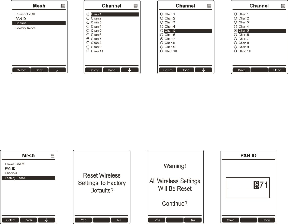
PAN ID
The AreaRAE Plus/Pro and any other devices that you want to interconnect wirelessly must have the
same PAN ID. You can set the PAN ID in the instrument or through ProRAE Studio II.
1. Press [Y/+] to increase the number and [N/-] to advance to the next digit.
2. After moving to the last digit and making changes, press [MODE].
Press [Y/+] to save the change.
Press [N/-] to undo the change.
AreaRAE Plus & AreaRAE Pro User’s Guide
48
Channel
The AreaRAE Plus/Pro and any other devices that you want to interconnect wirelessly must be operating
on the same channel.
1. Press [N/-] to step through the channel numbers from 1 through 10.
2. Once your selection is highlighted:
Press [Y/+] to select the channel.
Press [Y/+] to save your choice or press [N/-] to undo your changes.
Note: You cannot change the channel setting on an instrument equipped with a radio modem that operates
at a frequency of 868 MHz.
Factory Reset
Restore all the wireless settings to their original factory defaults.
Caution! Once you reset the wireless settings, you cannot retrieve any of the settings deleted by
performing this reset.
Press [Y/+] to reset the wireless settings.
Press [N/-] to exit without resetting the wireless settings.
AreaRAE Plus & AreaRAE Pro User’s Guide
49
12.3.6 ISM
The AreaRAE Plus/Pro and any other devices that you want to interconnect wirelessly through ISM must
have the same Network ID (1 to 4095, but do not use 255), as well as a unique Unit ID (1 through 64).
You can set the Network ID in the instrument or through ProRAE Studio II.
1. Press [Y/+] to increase the number and [N/-] to advance to the next digit.
2. After moving to the last digit and making changes, press [MODE].
Press [Y/+] to save the change.
Press [N/-] to undo the change.
Power On/Off
You can turn the ISM radio’s power on or off.
1. Press [Y/+] to see on or off state, and which is selected.
2. Press [N/-] to scroll to “On” or “Off.”
3. Press [Y/+] to select.
4. Press [Y/+] to “Save.” You can also press [N/-] to undo.
Network ID
Every ISM network must have a Network ID, which identifies that network and all equipment
operating in that network. All instruments, including the host, repeaters, etc., in the same
network need to be configured with the same Network ID.
1. Press [Y/+] to increase the number and [N/-] to advance to the next digit.
2. After moving to the last digit and making changes, press [MODE].
Press [Y/+] to save the change.
Press [N/-] to undo the change.
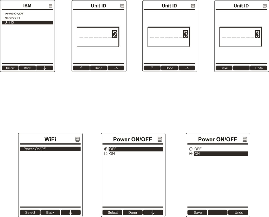
AreaRAE Plus & AreaRAE Pro User’s Guide
50
Unit ID
Each instrument in an ISM network must be assigned a unique Unit ID (between 00 and 99).
Make sure that the unit ID is not duplicated among any of the units within the same network.
1. Press [Y/+] to increase the number and [N/-] to advance to the next digit.
2. After moving to the last digit and making changes, press [MODE].
Press [Y/+] to save the change.
Press [N/-] to undo the change.
12.3.7 WiFi
You can turn the WiFi radio’s power on or off.
1. Press [Y/+] to see on and off states, and which is selected.
2. Press [N/-] to scroll to “On” or “Off.”
3. Press [Y/+] to select.
4. Press [Y/+] to “Save.” You can also press [N/-] to undo.
In order to communicate via WiFi, you must configure WiFi settings for the AreaRAE Plus/Pro to match
your router by using ProRAE Studio II:
1. Connect a USB cable between the AreaRAE Plus/Pro and a PC running ProRAE Guardian.
2. In Normal mode, press the [N/-] key until the screen shows “Enter Communication Mode?”
3. Press [Y/+].
4. Start ProRAE Studio II on the PC.
5. Log in as Administrator. You must provide a password (the default is “rae”.)
6. Click the “A” (for Automatic) detection.
7. When the AreaRAE Plus/Pro shows up in the list, click on it and then click “Select.”
8. Click “Setup” when the list of items is shown on the left. This downloads the instrument’s setup.
9. Click “WiFi.” This is where you see the current WiFi parameters and can set new ones.
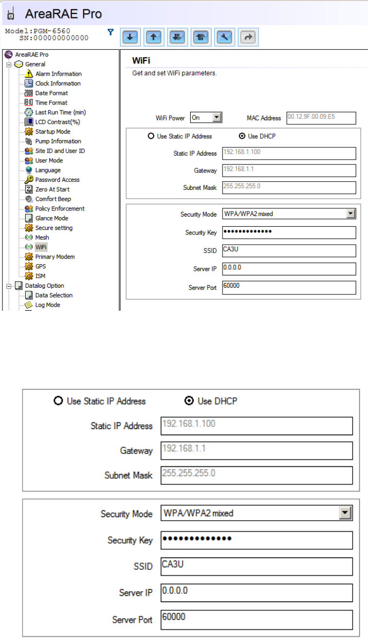
AreaRAE Plus & AreaRAE Pro User’s Guide
51
10. It is recommended that you select “Use DHCP” to dynamically set up the correct settings. If you
must use a Static IP Address (many corporate enterprises require it), check with your I.T.
administrator.
11. Settings for “Security Mode,” “Security Key,” and “SSID” must match the settings on the router
associated with the PC or server running ProRAE Guardian.
12. Settings for “Server IP” and “Server Port” must match those of the PC or server running ProRAE
Guardian.
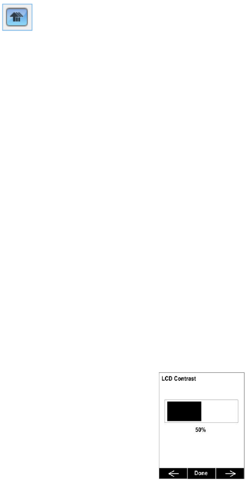
AreaRAE Plus & AreaRAE Pro User’s Guide
52
13. Once your settings are made, upload the settings to the AreaRAE Plus/Pro. Click this icon:
14. When uploading is finished, quit ProRAE Studio II.
15. On the AreaRAE Plus/Pro, press [Y/+] to exit Communication mode.
16. Disconnect the USB cable.
12.3.8 Monitor
The submenus under “Monitor” control the following:
LCD Contrast
Pump Speed
Zero At Start
Fast Startup
Language
Site ID
User ID
Secure In Place
Press [N/-] to advance through the submenus, and when you reach the last one, it returns to the first
selection.
LCD Contrast
The display’s contrast can be increased or decreased from its default setting. You may not need to ever
change the default setting, but sometimes you can optimize the display to suit extreme temperature and
ambient brightness/darkness conditions.
1. Use the [Y/+] and [N/-] keys to decrease or increase LCD contrast, respectively (the bar graph
aids in setting it).
2. When you are done, press [MODE] to select “Done.”
If you have not made a change, it exits to the submenu’s next selection. If you have made a change, you
are prompted at the next screen to press [Y/+] to save the change or [N/-] to undo the change and exit to
the next submenu selection.
Pump Speed
The AreaRAE Plus/Pro’s pump can operate at two speeds, high and low. It is recommended that you run
the pump at high speed.
1. Press [Y/+] to see the current, selected setting.
2. Press [N/-] to scroll to “High” or “Low.”
AreaRAE Plus & AreaRAE Pro User’s Guide
53
3. Press [Y/+] to select.
4. Press [Y/+] to “Save.” You can also press [N/-] to undo.
Zero At Start
If your AreaRAE Plus/Pro has been configured to perform a zero (fresh air) calibration upon startup,
called Zero At Start, then the startup routine is interrupted so that you can perform a fresh air calibration
for all sensors prior to using the instrument.
1. Press [Y/+] to see on or off state, and which is selected.
2. Press [N/-] to scroll to “On” or “Off.”
3. Press [Y/+] to select.
4. Press [Y/+] to “Save.” You can also press [N/-] to undo.
If you do not want to perform a zero calibration, press [MODE] to bypass it. If you start a zero calibration
and want to abort it, press [N/-], and the calibration stops and the main display is shown.
Fast Startup
Fast Startup reduces the amount of time between when the instrument is turned on and is ready for use. It skips
showing you many settings and is best suited to environments where the AreaRAE Plus/Pro is turned on and
off very often during a given day. If Fast Startup is not selected, then when the instrument starts, it shows you
details of each sensor, including calibration information, high and low alarm settings, etc.
1. Press [Y/+] to see on or off state, and which is selected.
2. Press [N/-] to scroll to “On” or “Off.”
3. Press [Y/+] to select.
4. Press [Y/+] to “Save.” You can also press [N/-] to undo.
Language
English is the default language, but other languages can also be selected for the instrument. Note: The
language can also be changed through ProRAE Studio II.
1. Press [Y/+] to see the current, selected language.
2. Press [N/-] to scroll to the language you want.
3. Press [Y/+] to select.
4. Press [Y/+] to “Save.” You can also press [N/-] to undo.
Site ID
Choose and enter an 8-digit Site ID to uniquely identify the particular site where the instrument is to be
used. The first four digits can be an alphabet letter or number, while the last four digits can only be
numbers. This Site ID is included in the datalog report.
Note: Advance through the alphabet and numbers (0 through 9) by one with each press of the [Y/+] key.
To scroll quickly, hold down the [Y/+] key for as long as you want it to scroll rapidly.
User ID
Enter an 8-digit alphanumeric User ID to uniquely identify a user. This User ID is included in the datalog
report. The first four characters of a customized User ID act as an identifier for montoring the instrument.
Note: Advance through the alphabet and numbers (0 through 9) by one with each press of the [Y/+] key.
To scroll quickly, hold down the [Y/+] key for as long as you want it to scroll rapidly.
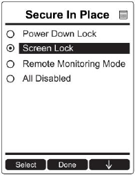
AreaRAE Plus & AreaRAE Pro User’s Guide
54
Secure In Place
Secure In Place provides anti-tampering features to prevent unwanted access to screens or functions.
These features use passwords to control access.
Power Down Lock: Requires that you enter the system password to power down the AreaRAE Plus/Pro.
Note: This feature is disabled by default, and is configurable via ProRAE Studio II and via the AreaRAE
Plus/Pro’s menu.
Screen Lock: AreaRAE Plus/Pro’s Screen Lock mode prevents changing the screen from the main
reading display without first entering a password. When Screen Lock is active, only the instantaneous
reading screen is displayed.
Note: When screen lock is active, the alarm test function is not available by pressing the [Y/+] key, and
the alarm test soft key is not displayed.
Remote Monitoring Mode: When AreaRAE Plus/Pro is programmed in Remote Monitoring mode, the
screen displays the text “Monitor Active,” indicating that the instrument is actively monitoring. During
alarm events, the display reverts to Screen Lock mode. Once the alarm conditions are cleared, Remote
Monitoring mode resumes.
Note: If enabled, Remote Monitoring mode is active upon entry to Normal mode, immediately after
startup, and/or upon exiting Programming mode.
To select a Secure In Place feature (or to disable all of them):
1. Press [Y/+] to see the currently selected mode.
2. Press [N/-] to scroll to the mode you want.
3. Press [Y/+] to select.
4. Press [Y/+] to “Save.” You can also press [N/-] to undo.
Your options are:
Power Down Lock
Screen Lock
Remote Monitoring Mode
All Disabled
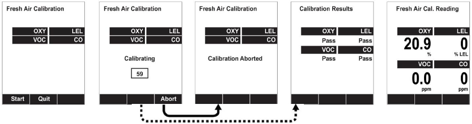
AreaRAE Plus & AreaRAE Pro User’s Guide
55
12.3.9 Calibration
Use this menu to perform a bump test or zero or span calibration for one or more sensors, and change the gas
concentration value used in bump tests and span calibration, as well as choose which sensors will be calibrated at the
same time.
Fresh Air
This procedure determines the zero point for all the sensors that require a zero calibration. For the oxygen
sensor, Fresh Air calibration sets the point equal to the concentration of oxygen in ambient air
(approximately 20.9% volume).
Note: Fresh air calibration is performed on all enabled gas sensors at the same time.
To perform Fresh Air calibration on multiple sensors:
1. Connect the instrument’s inlet to a source of dry, clean ambient air.
2. At the Calibration Menu, select “Fresh Air.” Press [Y/+] once to enter the fresh air calibration sub-
menu.
3. Start the flow of dry zero air, if used.
4. Press [Y/+] to start fresh air calibration.
5. A countdown screen appears. You can abort the calibration at any time during the countdown by
pressing [N/-].
6. If the calibration is not aborted, the display shows the sensor names and tells you whether the fresh air
calibration passed or failed, followed by the sensors’ fresh air readings.
Multi Sensor Span
Depending on the configuration of your AreaRAE Plus/Pro and the span gas you have, you can perform a
Span calibration simultaneously on multiple sensors.
The selected sensors are shown on the screen, along with the concentration settings for their Span gas.
With calibration gas connected to the instrument, start a multi span by applying gas to the instrument.
Calibration should start after a few seconds. If not, press [Y/+]. If you do not want to perform a multi
span, press [MODE].
Note: You can abort a multi span by pressing [N/-] once testing has started.
When the Multi Span is done, a screen is shown, with the sensor names and either “Pass” or “Fail” shown
next to them.
Note: Dotted line indicates automatic progression.
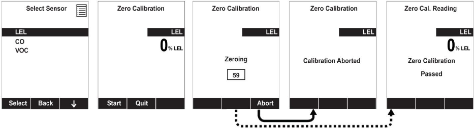
AreaRAE Plus & AreaRAE Pro User’s Guide
56
Single Sensor Zero
This allows you to perform zero (fresh air) calibration on individual sensors. Even though most toxic gas
sensors can be zeroed in fresh air, some sensors such as a parts-per-billion PID sensor for volatile organic
compounds (VOCs) should not be zeroed in fresh air. VOCs are normally present in ambient air, so
zeroing these sensors in ambient air will not allow for a true zero to be set for such sensors. The parts-per-
billion PID sensor with should only be zeroed with zero air or in ambient air using a charcoal filter or a
VOC zeroing tube.
1. If you are using a charcoal filter, connect it to the instrument.
2. If you are using dry air, connect the instrument to a source of zero air.
3. At the Calibration Menu, select “Single Sensor Zero.” Press [Y/+] once to enter the zero calibration
sub-menu.
4. Start the flow of zero air, if used.
5. Press [Y/+] to start zero calibration.
6. A countdown screen appears. You can abort the calibration at any time during the countdown by
pressing [N/-].
7. If the calibration is not aborted, the display shows the sensor names and tells you whether the zero
calibration passed or failed, followed by the sensors’ zero calibration readings.
Note: Dotted line indicates automatic progression.
AreaRAE Plus & AreaRAE Pro User’s Guide
57
Single Sensor Span
Instead of performing a span calibration on multiple sensors simultaneously, you can select a single
sensor and perform a span calibration.
Note: If a calibration icon (bottle with bottom portion filled in) is shown next to any of the sensors, it
means that the sensor is due for a full calibration.
To perform span calibration of an individual sensor, follow these steps:
1. At the Calibration Menu, select “Single Sensor Span.”
2. Select a sensor to calibrate from the list.
3. Install the “T” tube and connect it to a source of calibration gas.
4. Verify that the displayed calibration value meets the concentration specified on the gas cylinder.
5. Start the flow of calibration gas.
6. Press [Y/+] to start calibrating or wait for calibration to start automatically.
7. A countdown screen appears. You can abort the calibration at any time during the countdown by
pressing [N/-].
Note: Dotted line indicates automatic progression.
AreaRAE Plus & AreaRAE Pro User’s Guide
58
8. If the calibration is not aborted, the display shows the sensor names and tells you whether the
calibration passed or failed, followed by the sensor readings.
Note: The gamma radiation sensor comes pre-calibrated from the factory and does not require routine
calibration. However, you can check it by placing a check-source on the rear of the AreaRAE Plus/Pro
equipped with a gamma sensor to check the readings. Place the check-source near the upper middle of the
rear of the instrument and hold it until you see the Gamma reading change in the display.
Multi Sensor Bump
Depending on the configuration of your AreaRAE Plus/Pro and the span gas you have, you can perform a
bump test simultaneously on multiple sensors.
The selected sensors are shown on the screen. With calibration gas connected to the instrument, start a
multiple bump test by applying gas to the instrument and pressing [Y/+]. If you do not want to perform a
multiple bump test, press [MODE].
Note: You can abort a multiple bump test by pressing [N/-] once testing has started.
When the Multi Bump test is done, a screen is shown, with the sensor names and either “Pass” or “Fail”
shown next to them.
AreaRAE Plus & AreaRAE Pro User’s Guide
59
Single Sensor Bump
This menu allows a bump test to be performed on an individual sensor of your choice.
Note: If a bump test icon (bottle with bottom portion not filled in) is shown next to any of the sensors, it
means that the sensor is due for a bump test.
To perform a bump test on an individual sensor, follow these steps:
1. At the Calibration Menu, select “Single Sensor Bump.”
2. Scroll down the list using [N/-], and then press [Y/+] to select a sensor to bump test.
3. Install the “T” tube and connect it to a source of calibration gas.
4. Verify that the displayed calibration value meets the concentration specified on the gas cylinder.
5. Start the flow of calibration gas.
6. Press [Y/+] to start calibrating or wait for the bump test to start automatically.
7. A countdown screen appears. You can abort the bump test at any time during the countdown by
pressing [N/-].
8. If the bump test is not aborted, the display shows the sensor names and tells you whether the bump
test passed or failed, followed by the sensor readings.
Important!
After each sensor is bump tested, and you press
“OK,” the next sensor in the menu list is highlighted.
Note: Dotted line indicates automatic progression.
AreaRAE Plus & AreaRAE Pro User’s Guide
60
Cal. Reference
It is sometimes desirable to calibrate a sensor (PID for VOC, and LEL) with a specific gas for best
response to a gas you are surveying. The Cal. Reference library contains a list of reference gases that can
be selected for the PID and LEL sensors. Choose the sensor, and then select from the list of reference
gases.
Change Cal. Gas
You can change the calibration gas for the AreaRAE Plus/Pro’s PID and LEL sensors. Select from a custom list
that you create (My List), the last ten gases used, the built-in gas library for your PID lamp, and user-defined
custom gases. Each gas is shown in the list for selection and the screen automatically changes to show its full name,
chemical formula, molecular weight (M.W.) and correction factor (CF).
Multi Cal. Select
This menu allows you to define a group of sensors to be bump tested and span calibrated together.
Simultaneous testing and calibration of multiple sensors shortens the bump test and calibration processes
and reduces the number of individual gas cylinders you need. For example, it may be more efficient to use
a single cylinder with a four-gas mix including 50% LEL Methane, 18% O2, 10 ppm H2S, and 50 ppm
CO, to calibrate the LEL, O2, CO, and H2S sensors at one time, compared to using four distinct gas
cylinders and calibrate these sensors individually in sequence. In order for sensors to be calibrated
together, all of them must be selected using Multi Cal. Select.
1. Scroll down the list of sensors using the [N/-] key.
2. Add or remove that gas from the list by pressing [Y/+]. An “X” in a box to the left of a sensor’s
name indicates it is selected.
3. Once you have made all your selections, press [MODE] for “Done.”
AreaRAE Plus & AreaRAE Pro User’s Guide
61
Change Span Value
You can individually set the span gas concentration for each sensor. This concentration setting will also
be used for a bump test. The units of measure (ppm, %LEL, etc.) are shown on the display.
1. Scroll down the list of sensors using the [N/-] key.
2. Press [Y/+] to select it.
3. Press [N/-] to step through the digits.
4. Press [Y/+] to increase the number from 0 through 9. Once the number 9 is reached, pressing
[Y/+] causes the numbers to “wrap around” to 0 and count up again.
5. Once you have set the desired value, press [MODE] for “Done.” This registers the new span value.
Change Span 2 Value
For enhanced accuracy, it is possible to perform a second Span calibration in addition to Zero
and Span calibrations. Your instrument first must be set to allow this third calibration. This
requires using ProRAE Studio II software and a PC, as well as a higher concentration of
calibration gas. Note: 3-point calibration is the default for AreaRAE Pro for ppb resolution or the
high range (0 to 5,000 ppm); for other configurations, 2-point calibration is the default.
Note: You can only disable 3-point calibration capability by using ProRAE Studio II again.
1. Press [Y/+] to select VOC.
2. Press [N/-] to step through the digits.
3. Press [Y/+] to increase the number from 0 through 9. Once the number 9 is reached, pressing
[Y/+] causes the numbers to “wrap around” to 0 and count up again.
4. Once you have set the desired value, press [MODE] for “Done.” This registers the new second span
value.
5. Press [Y/+] for “Save” and [N/-] for “Undo.”

AreaRAE Plus & AreaRAE Pro User’s Guide
62
12.3.10 LEL Calibration Procedure
You must perform a separate zero calibration for the LEL sensor and then perform a span calibration.
Important! Before calibrating, make sure pump is on its high setting. This is in the “Pump Speed” submenu
under the “Monitor” menu item.
To calibrate the LEL sensor, follow these two procedures:
Zero Sensor Calibration For The LEL Sensor
1. Turn on the AreaRAE Plus/Pro and allow it to warm up for 20 minutes in ambient air.
2. In Programming mode, Select “Calibration” and then select “Single Sensor Zero.”
3. Select “LEL.”
4. Calibrate the LEL sensor’s zero point with ambient air.
5. After zero calibration is complete, press [MODE] to return to the Calibration menu. “Single
Sensor Span” is highlighted
Span Calibration For The LEL Sensor
1. Press [Y/+] to select “Single Sensor Span.”
2. Press [N/-] until “LEL Sensor” is highlighted.
3. Press [Y/+] to select “LEL Sensor.”
4. Screw one end of a “T” using Teflon tubing to the AreaRAE Plus/Pro filter on the inlet. (You can use
RAE Systems P/N: W01-3003-000).
5. Attach the other end to the flow regulator of a calibration cylinder with 50% LEL methane (unless
otherwise specified ). The flow rate should not be less than 750cc/min.
6. Start the flow of calibration gas.
7. Press [Y/+] to start calibration.
8. When calibration is complete, shut off the calibration gas flow and disconnect the calibration tubing.
9. Press [MODE] to exit to the menu. (You may perform other calibrations. Otherwise, exit.)

AreaRAE Plus & AreaRAE Pro User’s Guide
63
13 User Modes
The AreaRAE Plus/Pro can be configured for two user modes, Basic and Advanced. The choice is
selected and set in ProRAE Studio II.
13.1 Basic User Mode
In Basic User Mode, some restrictions are applied, including password protection that guards against
entering Programming Mode by unauthorized personnel.
13.2 Advanced User Mode
In Advanced User Mode, there are no access restrictions (you do not need a password), and the AreaRAE
Plus/Pro provides the indications and data you need most for typical monitoring applications.
14 Policy Enforcement
The AreaRAE Plus/Pro can be configured to enforce a facility/company’s requirements that calibration
and/or bump testing be performed at specified intervals, and to explicitly prompt the user that
calibration/bump testing is required. Depending on how Policy Enforcement features are configured, the
user may be required to perform a bump test or calibration prior to being able to use the instrument. That
is, it can be set to not allow normal operation of the instrument unless calibration or bump testing is
performed.
If the instrument has been bump tested and calibrated in compliance with the policy settings, a
check-mark icon is included along the top of the AreaRAE Plus/Pro screen:
If Policy Enforcement is enabled, then after startup the AreaRAE Plus/Pro displays a screen that informs
the user that the instrument requires either a bump test or a calibration. If both are required, then they are
shown in sequence.
Note: Policy enforcement features are disabled by default.
14.1 Setting Policy Enforcement
You must use ProRAE Studio II to make changes to Policy Enforcement settings. The procedure requires
connecting the AreaRAE Plus/Pro via USB cable to a PC running ProRAE Studio II. Policy violations are
captured in the datalog.
1. Connect a USB cable between the AreaRAE Plus/Pro and a PC with ProRAE Studio II.
2. Put the AreaRAE Plus/Pro into PC Communications Mode.
3. Start ProRAE Studio II software on the PC.
4. Select “Administrator” and input the password (the default is “rae”).
5. Click “Detect the instruments automatically” (the magnifying glass icon with the letter “A” in it).
After a few seconds, the AreaRAE Plus/Pro is found and it is shown, along with its serial number:
6. Click on the icon to highlight it, and then click “Select.”.
7. Click “Setup.”
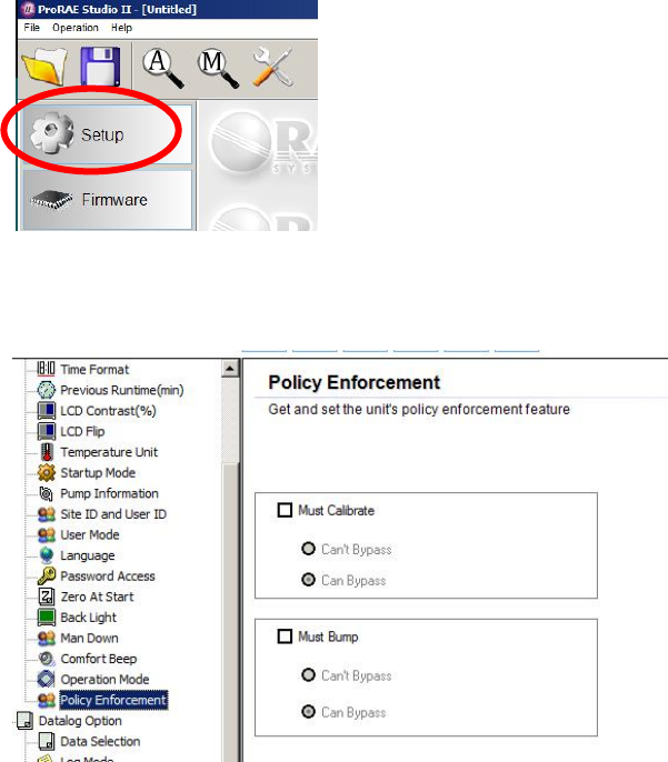
AreaRAE Plus & AreaRAE Pro User’s Guide
64
8. In the menu that now appears on the left side, click “Policy Enforcement.” It is highlighted, and the
Policy Enforcement pane is shown:
For “Must Calibrate” and “Must Bump,” you have the options of no enforcement or enforcement
(including “Can’t Bypass,” and “Can Bypass”).
Must Calibrate. The user is prompted to calibrate the instrument when calibration is due (as set by the
calibration interval). There are two programmable options:
Can’t Bypass. Unless calibration is performed, the instrument cannot be used, and the only
option is to turn off the instrument.
Can Bypass. If calibration is due but the user does not want to perform a calibration, the
instrument can still be used. In this case, the instrument records that the user has bypassed the
calibration requirement in a Policy Violation report.
Must Bump. The user is prompted to bump test the instrument when a bump test is due (as set by the
bump test interval). There are two programmable options:
Can’t Bypass. Unless a bump test is performed, the instrument cannot be used, and the only
option is to turn off the instrument.
Can Bypass. If a bump test is due but the user does not want to perform one, the instrument can
still be used. In this case, the instrument records that the user has bypassed the bump testing
requirement in a Policy Violation report.
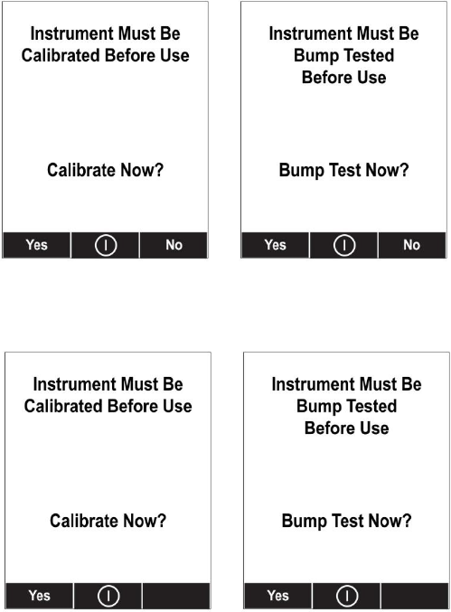
AreaRAE Plus & AreaRAE Pro User’s Guide
65
These are the screens that are shown on an AreaRAE Plus/Pro after startup if “Can Bypass” is selected:
If “Can’t Bypass” is selected, the display looks like this, and only allows the options of performing the
test or shutting down:
16. Once you have made your selections in ProRAE Studio II, you must upload the changes to the
instrument. Click the icon labeled “Upload all settings to the instrument.”
17. A confirmation screen is shown. Click “Yes” to perform the upload, or “No” to abort.
Uploading takes a few seconds, and a progress bar is shown. You can abort the upload by clicking
“Cancel.”
18. Exit ProRAE Studio II.
19. Press [Y/+] on the AreaRAE Plus/Pro to exit Communication Mode.
14.2 Deactivating Policy Enforcement
If the AreaRAE Plus/Pro screen displays the message that it must be bump tested or calibrated, and if the
option to bypass bump testing or calibration is not available, you should shut off the instrument and
follow the procedure outlined here if you want to change the Policy Enforcement settings:
1. Use a USB cable to connect the AreaRAE to a computer running ProRAE Studio II.
2. Enter Diagnostic Mode on the AreaRAE Plus/Pro (with the instrument turned off, press and hold
[Y/+] and [MODE] until it starts up.
3. After startup, enter the password when prompted (default is “0000”) and press [MODE].
4. Press [N/-] repeatedly until you see the “Enter Communications Mode?” screen.
5. Press [Y/+] to enter Communications Mode.
6. Start ProRAE Studio II.
7. Select “Administrator.”

AreaRAE Plus & AreaRAE Pro User’s Guide
66
8. Input the password (the default is “rae”).
9. Click “OK.”
10. Click “A” (detect instruments automatically).
11. Click on the instrument’s icon when it appears.
12. Click “Select.”
13. Click “Setup.”
14. Click “Policy Enforcement.” The Policy Enforcement pane is shown.
15. Deselect Policy Enforcement features you do not wish to use.
16. Click “Upload all settings to the instrument.”
17. When you see this confirmation. Click “Yes.”
Uploading will take a few seconds, and this progress bar is shown:
18. When the upload is done, exit ProRAE Studio II.
19. Press [Y/+] on the AreaRAE Plus/Pro to exit Communication Mode.
AreaRAE Plus & AreaRAE Pro User’s Guide
67
15 Calibration And Testing
15.1 Manual Alarms Test
Under Normal Operation Mode and non-alarm conditions, the buzzer (audible alarm), visible alarms, and
backlight can all be tested anytime by pressing [Y/+] twice. If any alarm does not respond, check the
alarm settings in the Programming Menu to make sure all alarms are enabled (selected setting under
Programming/Alarms/Alarm Settings should be “All Enabled”). If any alarms are enabled but not
functional, the instrument should not be used.
15.2 Bump Testing And Calibration
RAE Systems recommends that a bump test be conducted prior to each day’s use. The purpose of a bump
test is to ensure that the instrument’s sensors respond to gas and all the alarms are enabled and functional.
The AreaRAE Plus/Pro multi-gas detector must be calibrated if it does not pass a bump test when
a new sensor is installed, after sensor maintenance has been performed, or at least once every 180
days, depending on use and sensor exposure to poisons and contaminants.
Calibration and bump test intervals and procedures may vary due to national legislation and
company policy.
During a bump test, the instrument makes a pass/fail decision based on sensor performance, but the user
still has the responsibility to make sure all the alarms are enabled and functional.
15.2.1 Bump (Functional) Testing
A bump test can be performed on an individual sensor (Single Sensor Bump) or a group of sensors (Multi
Sensor Bump) combined into Multi Cal. Select. The same gas is used for a bump test as for calibration.
Typically, two cylinders of calibration gas are needed to perform a bump test or calibration on an
instrument with a PID sensor and electrochemical and LEL sensors. This may require one gas cylinder
with Isobutylene or another VOC test gas to test the PID sensor, and another with a 4-gas mix to test
electrochemical (such as CO, H2S, and O2) and LEL sensors. As with calibration, the instrument
intelligently splits the process into two consecutive steps: first, the wizard prompts for testing
electrochemical and LEL sensors, and then it tests the PID sensor.
IMPORTANT!
Make sure all of the instrument’s sensors have warmed up before performing a bump test. The instrument
will take the time to warm up the sensors prior to enabling access to bump test menus. You can tell a
sensor has warmed up if you see a reading next to it name on the display. If it has not warmed up, you see
three dashes (“---”) next to it.
Teflon tubing must be used to test or calibrate the PID sensor. Follow the steps described here to perform
a manual bump test:
1. Turn on your AreaRAE Plus/Pro by pressing and holding [MODE] (the middle button) and allow
the instrument to boot up fully until the main measurement screen with sensor names and
readings is shown.
2. Enter the Bump Test menu. It is accessible either through Programming Menu.
AreaRAE Plus & AreaRAE Pro User’s Guide
68
3. Connect the AreaRAE Plus/Pro to the calibration gas. Turn on the gas to initiate flow.
4. Press [Y/+] to start the bump test. While the bump test is being performed, the readings for each
sensor are shown. Once the bump test completes, pass/fail test results and readings are shown for
each sensor.
Note: If a PID or other sensors are installed in the instrument require a dedicated cylinder of gas
to calibrate, the instrument will prompt for calibrating such sensors at this point.
IMPORTANT!
If one or more sensors fails a bump test, be sure to calibrate those sensors.
5. The bump test is now complete. Press Exit to return to the main measurement screen.
6. Now perform a manual alarms test (see page 67).
If all the alarms and all sensors have passed and no sensor is due for a calibration, the instrument is now
ready for use.
Note: When a manual bump test is performed, the readings shown are in the equivalent units of the
calibration gas, and not the measurement gas (if different).
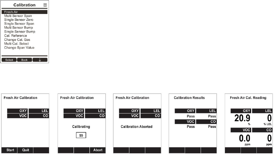
AreaRAE Plus & AreaRAE Pro User’s Guide
69
15.2.2 Testing The Gamma Radiation Sensor
The gamma radiation sensor does not require user calibration. To check whether the sensor is
operational, place a gamma check-source on the upper half of the rear of the AreaRAE Plus/Pro
equipped with a gamma sensor. The reading should increase.
15.2.3 Zero Calibration For Parts-Per-Billion (ppb) PID Sensor
IMPORTANT! The parts-per-billion PID sensor for volatile organic compounds (VOCs) should not be
zeroed in fresh air. VOCs are normally present in ambient air, so zeroing the sensor in ambient air will
not allow for a true zero to be set. The parts-per-billion PID sensor should be zeroed with ambient air
using a charcoal filter or a VOC zeroing tube. Refer to the procedure on page 71.
15.2.4 Fresh Air Calibration
This procedure determines zero points of most sensors. The AreaRAE Plus/Pro should be zero-calibrated
in clean air with 20.9% oxygen or with a cylinder of clean zero air.
Note: If you use a zero air cylinder, you must connect it directly to the filter that is attached to the
instrument’s inlet.
At the Calibration menu, select “Fresh Air” by pressing [Y/+] once to enter fresh air calibration.
After a timer countdown, the zero calibration is done. The LCD displays the sensor names and tells you
whether each calibration passed or failed, followed by the sensor readings.
Note: You can abort the calibration at any time during the countdown by pressing [N/-].

AreaRAE Plus & AreaRAE Pro User’s Guide
70
15.3 Span Calibration
This procedure determines the second point of the sensor calibration.
Note: When a manual calibration is performed, the readings shown are in the equivalent units of the
calibration gas, and not the measurement gas.
15.4 Three-Point Calibration For Enhanced Linearity With Extended-
Range And ppb PID Sensors
For better linearity at higher concentrations when an AreaRAE Plus/Pro is equipped with a PID sensor, a
3-point calibration can be performed.
IMPORTANT!
Three-point calibration is disabled by default, but can be enabled using ProRAE Studio II Instrument
Configuration and Data Management software on AreaRAE Plus/Pro instruments with 10.6eV PID
sensors, including high-range ppm and ppb PID sensors.
Default calibration gas settings for AreaRAE Plus/Pro PID sensors are as follows:
Sensor
Specifications
Zero
Span
Span 2
(Third
calibration point,
if enabled)
AreaRAE Plus/Pro
parts-per-billion
(ppb) PID
0 to 2,000 ppm
range, 10 ppb
resolution
With a
charcoal
filter or VOC
zeroing tube
10 ppm Isobutylene
100 ppm
Isobutylene
AreaRAE Plus/Pro
extended-range ppm
PID
0 to 5,000 ppm
range, 0.1 ppm
resolution
Fresh air or
dry air
100 ppm Isobutylene
1,000 ppm
Isobutylene
AreaRAE Plus/Pro
9.8eV PID
0.1 to 2,000 ppm;
0.1 ppm resolution
Fresh air or
dry air
100 ppm Isobutylene
5 ppm Benzene
Not supported
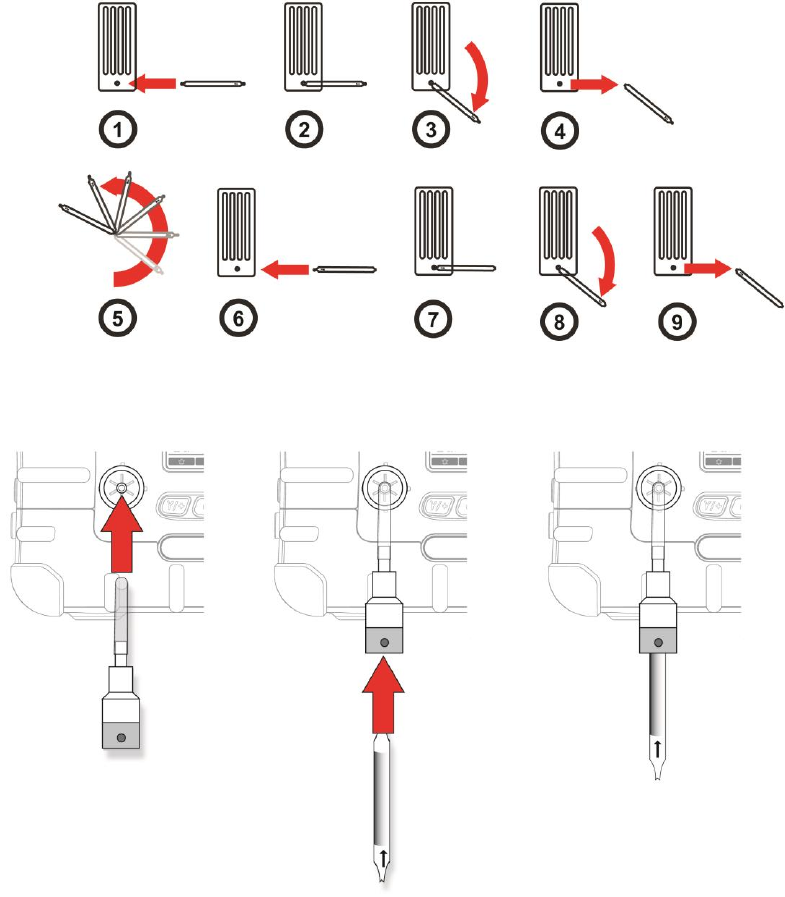
AreaRAE Plus & AreaRAE Pro User’s Guide
71
15.4.1 VOC Zero Calibration Procedure For Enhanced Linearity With Extended-
Range And ppb PID Sensors
You will need a VOC Zeroing Tube Adapter (P/N: 025-3002-000) and a VOC Zeroing Tube (P/N: 025-
2000-010).
1. Inspect the external filter on the instrument and replace it if it appears to be dirty.
2. Break the two ends of a VOC Zeroing Tube by putting the ends into the small hole near the bottom of
the tube box and snapping them off.
3. Connect the VOC Zero Tube Adapter to the external filter on AreaRAE Pro/Plus, and then insert one
end of the VOC Zeroing Tube into the adapter. The arrow on the tube indicates the correct direction.
4. Run the zeroing calibration procedure for the instrument.
5. After zero calibration, properly dispose of the used VOC zeroing tube (it is designed for single use
only), and remove the VOC Zeroing Adapter.
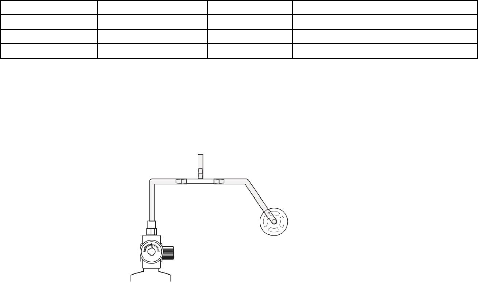
AreaRAE Plus & AreaRAE Pro User’s Guide
72
15.4.2 Enabling 3-Point Calibration Via ProRAE Studio II
The AreaRAE Plus/Pro must be connected to a PC through the supplied USB cable and must be in the PC
Communications mode.
1. Start up the ProRAE Studio II software, enter a password, and detect the instrument following the
directions provided in the ProRAE Studio II User’s Manual.
2. Click “Setup” to download the AreaRAE Plus/Pro’s current configuration information
3. Click “Sensor Information.”
4. Click the “+” to the left of “Sensor Summary” to show the list of installed sensors.
5. Click “VOC(ppm)” or “VOC(ppb)” to get and set sensor parameters.
6. Click 3-Point Calibration (the check mark should now be showing).
7. Click the “Upload all settings to the instrument” icon. You will be asked whether you want to
upload all configurations to the instrument. Click “Yes.”
8. When you are done, quit ProRAE Studio II and then press [Y/+] on the AreaRAE Plus/Pro to exit
the PC communications mode. The instrument returns to operating in Normal mode.
15.4.3 Calibration Setup
For single-sensor and multi-sensor span calibration, there are three methods for calibrating. Each
has different regulator type, flow rate, and pressure compensation requirements:
Regulator Type
Flow Rate
T-Tube Necessary?
Good
Constant Flow
500 cc/min
No
Better
Constant Flow
750 cc/min
Yes
Best
Demand Flow
--
No
Using A T-Tube
Using Teflon tubing, attach one end of a “T” to the external filter on the AreaRAE Plus/Pro inlet. (You can use
RAE Systems P/N: W01-3003-000).
Calibrating Without A T-Tube
Use Teflon tubing to connect the calibration gas cylinder’s regulator to the external filter on the AreaRAE Plus/Pro
inlet.
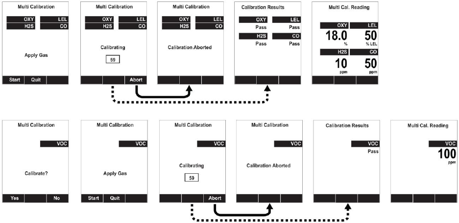
AreaRAE Plus & AreaRAE Pro User’s Guide
73
Multi-Sensor Span Calibration
This lets you perform a span calibration on multiple sensors simultaneously. It requires using the
appropriate span gas and that the concentration labeled on the gas cylinder matches the concentration
programmed in the AreaRAE Plus/Pro.
Teflon tubing must be used to test or calibrate the PID sensor. Follow the steps described here to perform
a multi-sensor span calibration:
1. Attach the “T” tube and connect gas to the AreaRAE Plus/Pro.
2. Start the flow of gas and then either press [Y/+] to begin calibration or wait for calibration to start
automatically once the sensor “senses” the gas. A countdown screen is shown. You can abort the
calibration at any time during the countdown by pressing [N/-].
If the calibration reaches its conclusion, it shows the sensor names and tells you whether the calibration
passed or failed, followed by the sensor readings.
Note: If there are other sensors to be calibrated at this stage, the screens will guide you through the
process.
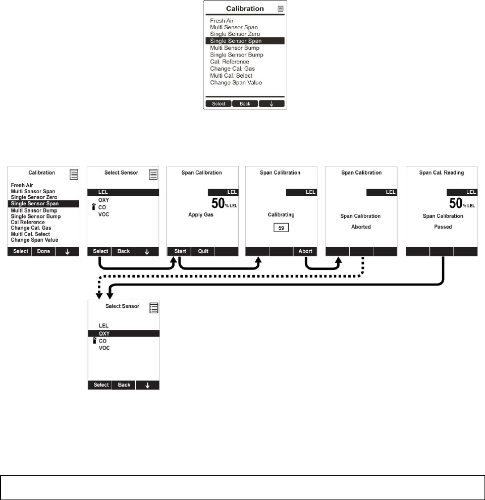
AreaRAE Plus & AreaRAE Pro User’s Guide
74
15.4.4 Single-Sensor Span Calibration
To perform span calibration of an individual sensor, follow these steps:
1. At the Calibration Menu, select “Single Sensor Span.”
2. Select a sensor from the list.
3. Connect the “T” tube and connect it to a source of calibration gas.
4. Verify that the displayed calibration value meets the concentration label on the gas cylinder.
5. Start the flow of calibration gas.
6. Press [Y/+] to start calibrating. You can abort the calibration at any time during the countdown by
pressing [N/-].
After a timer countdown, the span calibration is done. The LCD will display whether the calibration was
successful and the reading for that calibration gas.
Note: If the sensor calibration fails, try again. If calibration fails repeatedly, turn off the instrument and
then replace the sensor.
WARNING: Do not replace sensors in hazardous locations.
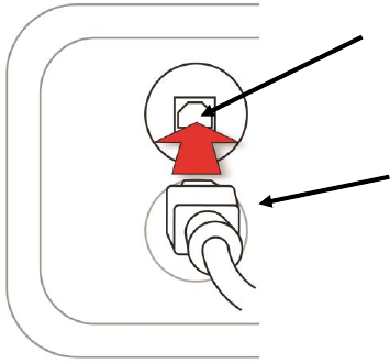
AreaRAE Plus & AreaRAE Pro User’s Guide
75
16 Datalog Transfer, Monitor Configuration, and Firmware
Upgrades Via Computer
Datalogs can be downloaded from the AreaRAE Plus/Pro to a computer, and firmware updates can be
uploaded to the AreaRAE Plus/Pro via the USB port on the side. Use the included USB cable to connect
the AreaRAE Plus/Pro to a computer running ProRAE Studio II.
16.1 Downloading Datalogs And Performing PC-Based Instrument
Configuration And Firmware Upgrades
The AreaRAE Plus/Pro communicates with a PC running ProRAE Studio II Instrument Configuration and
Data Management software to download datalogs, configure the instrument, or upgrade the instrument’s
firmware.
Note: The most recent version of ProRAE Studio II Instrument Configuration and Data Management
software is available for a free-of-charge download at: http://www.raesystems.com/downloads/product-
software .
1. Use the supplied PC Communications Cable to connect the AreaRAE Plus/Pro to a PC.
2. Turn on the AreaRAE Plus/Pro. Make sure it is running in Normal mode (with the main
measurement screen showing).
3. Activate the PC communications mode on the AreaRAE Plus/Pro by pressing [N/-] repeatedly,
starting from the main measurement screen until you reach the “Enter Communication Mode?”
screen.
4. Press [Y/+]. Measurement and datalogging stop, and the instrument is now ready to communicate
with the PC. The display now says “Ready To Communicate With Computer.”
5. Start up the ProRAE Studio II software, enter a password, and detect the instrument following the
directions provided in the ProRAE Studio II User’s Guide.
6. Follow the instructions in the ProRAE Studio II User’s Guide to download the datalog, configure
the instrument settings, or update the AreaRAE Plus/Pro’s firmware.
7. When you are done, press [Y/+] to exit the PC communications mode on the AreaRAE Plus/Pro.
The instrument returns to operating in Normal mode.
IMPORTANT!
Always securely close the cover over the USB port when it is not in use. This keeps moisture and debris
out of the port.
USB cable
USB port
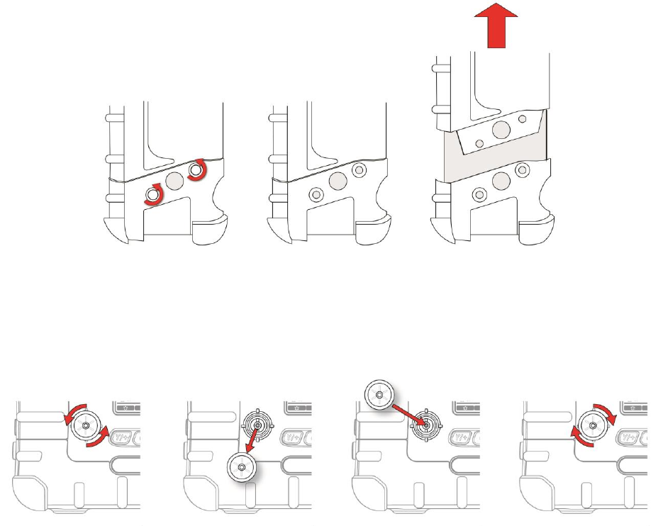
AreaRAE Plus & AreaRAE Pro User’s Guide
76
17 Maintenance
The AreaRAE Plus/Pro requires little maintenance, aside from replacing sensors, the filter, and the
battery. The pump may need replacement, as well. If the instrument has a PID, then the PID sensor lamp
and sensor electrode panel may require periodic cleaning.
17.1 Removing/Installing The Rubber Boot
In order to open the AreaRAE Plus/Pro, it is necessary to remove the belt clip and the rubber boot. Note
that there are two hex screws on the bottom rear side that secure the boot.
1. Turn off the instrument.
2. Remove the external filter.
3. Remove the wind sensor (if one is attached).
4. Unscrew the two the two screws on each side.
5. Slide the top part of the boot upward until it clears the top of the instrument.
6. Slide off the bottom portion of the boot.
17.2 Replacing The External Filter
If a filter is dirty or clogged, remove it by unscrewing it from the black gas inlet adapter on the front of
the instrument. Discard it and replace it with a new filter (P/N: 008-3022-000). Perform a pump stall test
to make sure the inlet and the external filter are installed properly so that there are no leaks in the system.
IMPORTANT!
An AreaRAE Pro/Plus must not be calibrated or operated without a filter. Operation without a filter may
damage the instrument.
a.
c.
b.
d.
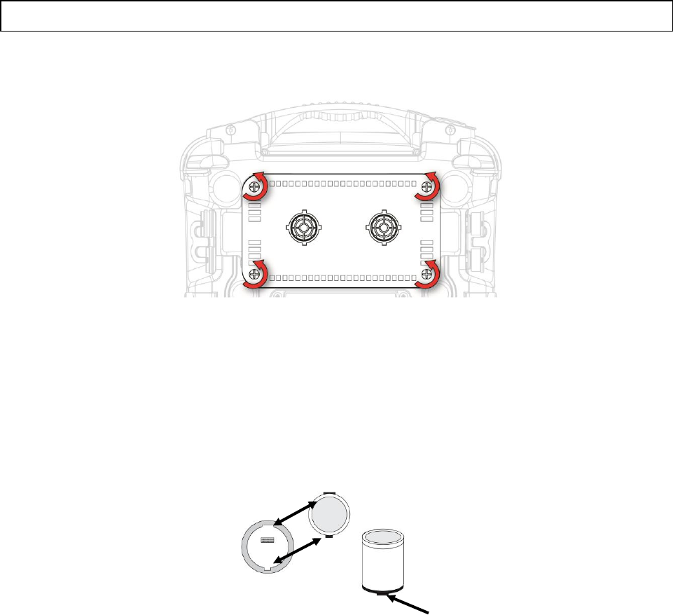
AreaRAE Plus & AreaRAE Pro User’s Guide
77
17.3 Removing/Cleaning/Replacing Sensor Modules
WARNING! Do not replace sensors in hazardous locations.
All sensors are located inside the sensor compartment in the upper half of the AreaRAE Plus/Pro. They
are accessed by removing the cover that is held on by four screws.
1. Turn off the instrument.
2. Remove the four screws holding the sensor compartment.
3. Remove the cover. The sensors are plugged into the slots.
4. Gently lift out the desired sensor module with your fingers.
5. Install the replacement sensor. It can only go into its slot one way. The connector inside the
AreaRAE Plus/Pro and the indexing guides are good visual indicators of how to set the sensor
into position. Make sure the indexing keys are aligned and press the sensor into place to ensure it
is seated firmly. Note that the sensors are also in different sizes, and one size cannot be
substituted for another.
Match index keys on
sensor module with
socket
Sensor
indexing
key
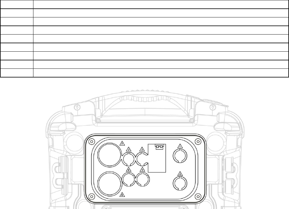
AreaRAE Plus & AreaRAE Pro User’s Guide
78
Sensor Locations
Location
Sensor type(s)
1
4R+ EC --- O2
2
4R+ EC or 4R+ PID
3
4R+ EC (avoid using O2 sensor in this slot)
4
4R+ EC
5
4R+ EC or LEL
6
4R+ EC (avoid using O2 sensor in this slot)
7
7R+ sensors
8
7R+ sensors
Note: The AreaRAE Plus/Pro does not allow duplicate sensors (that is, two or more of the same kind,
including, for example, a 4R+ PID and a 7R+ PID) to operate simultaneously. Therefore, if duplicate
sensors are inserted in the slots, when the instrument is turned on, it automatically senses the redundancy
and only allows operation of one of the sensors, selecting the sensor in the location with the lowest
number.
WARNING!
If you are removing a sensor and not replacing it, its slot cannot be left empty. A “dummy” sensor must
be installed in the empty slot.
17.4 Cleaning Or Replacing The PID
Note: The cleaning procedure is not normally needed. Clean the PID sensor module, the lamp and the
lamp housing only when one of the following has happened:
1. The reading is inaccurate even after calibration.
2. The reading is very sensitive to air moisture.
3. A chemical liquid has been sucked into the unit and damaged the unit.
Use of the external filter helps to prevent contamination of the sensor.
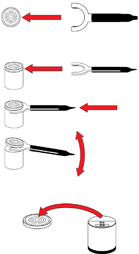
AreaRAE Plus & AreaRAE Pro User’s Guide
79
17.4.1 Cleaning Or Replacing The 4R+ PID
1. Gently lift out the PID module with your fingers.
2. If the module requires replacement (because the lamp does not illuminate, or the module has been
used past its expiration date), place a new module into the slot, being careful to match the
indexing keys. The sensor can only go into its slot one way. Refer to step 11 for alignment
information.
3. If you want to open the sensor module to inspect and clean the lamp and sensor electrode panel,
you must use the special tool (P/N: G02-0306-003). The special tool’s “C”-shaped end has small
“teeth” inside. Slide the tool so that the teeth slip into the notch between the module’s cap and
body:
4. Gently pry up the cap using a rocking motion:
5. Once the cap is removed, set it aside.
AreaRAE Plus & AreaRAE Pro User’s Guide
80
6. Now lift the sensor electrode panel from the module:
7. Clean the sensor electrode panel in a solution of isopropanol lamp cleaner (included, along with
cleaning swabs, in a PID Lamp Cleaning Kit, part number 500-0014-010, package of 10), and
allow it to dry.
8. Clean the lamp’s window with a cleaning swab dipped in isopropanol lamp cleaner, and allow it
to dry. Do not touch the lamp window with your fingers, as the residual oils will shorten its life.
9. Inspect the electrical contacts. Clean them with a swab dipped in lamp cleaner if they appear to
need cleaning (make sure the contacts are not pressed down when you are done):
10. Reassemble the sensor module by placing the sensor electrode panel back in place and firmly
pressing the cap back onto the top.
11. Place the sensor module back into the AreaRAE Plus/Pro. Make sure the index points are aligned
(it can only go in one way).
12. Carefully place the cap back onto the AreaRAE Plus/Pro and tighten the screw.
Match index
points on sensor
module with
sensor slot
AreaRAE Plus & AreaRAE Pro User’s Guide
81
17.4.2 Cleaning Or Replacing The 7R+ PID
Note: Always calibrate the AreaRAE Plus/Pro after replacing the sensor module.
1. Gently lift out the PID module from the instrument with your fingers.
2. If the module requires replacement (because the lamp does not illuminate, or the module has been
used past its expiration date), place a new module into the slot, being careful to match the
indexing keys. The sensor can only go into its slot one way.
If you want to open the sensor module to inspect and clean the lamp and sensor electrode panel, you must
use the special 7R+ PID Sensor Cover Opening Tool (P/N: C04-2025-000).
1. Press the tool down around the sensor module, making sure to align the arrow on the module and
the tool:
2. Check that the alignment of the two arrows is correct:
3. Locate the notch on the side of the sensor module.
AreaRAE Plus & AreaRAE Pro User’s Guide
82
4. Place the tip of a flat-blade screwdriver in the slot and gently pry up on the cover, using
the tool for leverage.
5. Once the cover is loose, remove the screwdriver.
6. Lift the lid off, exposing the sensor electrode panel.
Sensor electrode
panel
AreaRAE Plus & AreaRAE Pro User’s Guide
83
7. Lift out the sensor electrode panel. The PID lamp’s window is now visible.
8. Use the 7R+ PID Lamp Removal Tool (P/N: C04-2026-000) to remove the lamp. With the tool’s
collar retracted (a), press down around the top of the lamp (b). Then press down the collar so that
the tool grips the lamp (c).
Sensor Electrode
Panel
PID lamp window
a.
c.
b.
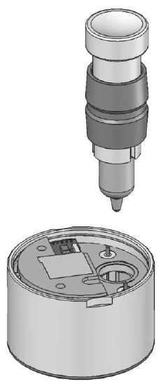
AreaRAE Plus & AreaRAE Pro User’s Guide
84
9. Gently lift the PID lamp out of the sensor module by pulling up.
Cleaning The PID Electrode Panel
Place the PID electrode panel into isopropanol. It is highly recommended that an ultrasound bath to be
used to clean it for at least 15 minutes. Then dry the electrode panel thoroughly. Never touch the
electrodes with your hand.
Also use an isopropanol-soaked cotton swab to wipe off the lamp housing where it contacts the sensor
when the sensor is installed.
Turn over the Electrode Panel so that the pins point up and the sensor cavity is visible. Examine the
sensor electrodes for any corrosion, damage, or bending out of alignment. The metal sensor electrode
“fingers” should be flat and straight. If necessary, carefully bend the sensor fingers to ensure that they do
not touch the Teflon portions and that they are parallel to each other. Make sure that the nuts on the
sensor pins are snug but not overtight. If the sensor is corroded or otherwise damaged, it should be
replaced.
Cleaning The Lamp Housing Or Changing The Lamp
If the lamp does not turn on, the instrument will display an error message to indicate replacement of the
lamp may be required.
1. If the lamp is operational, clean the lamp window surface and the lamp housing by wiping it with
isopropanol using a cotton swab using moderate pressure. After cleaning, hold the lamp up to the
light at an angle to detect any remaining film. Repeat the process until the lamp window is clean.
Never use water solutions to clean the lamp. Dry the lamp and the lamp housing thoroughly after
cleaning.
CAUTION: Never touch the window surface with the fingers or anything else that may leave a
film. Never use acetone or aqueous solutions.
2. If the lamp does not turn on, remove the lamp from the lamp housing. Insert the new lamp, avoiding
contact with the flat window surface.
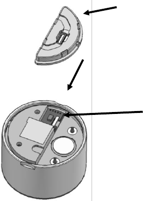
AreaRAE Plus & AreaRAE Pro User’s Guide
85
3. Reinstall the PID sensor module by pressing it into place with a soft, non-woven cloth. It is not
necessary to press excessively. When the Electrode Panel and Lamp Housing Cap are replaced, the
PID sensor will be properly seated.
4. Inspect the two electrical contacts (pins) to make sure they are not pressed down.
5. Replace the Electrode Panel.
IMPORTANT!
Make sure the Electrode Panel is inserted with the correct side up. The bottom of the Electrode Panel
is larger than the top, and it fits into the top of the Sensor Module directly over the PID Lamp
Window (the word “UP” is imprinted on the top of the Electrode Panel). If the Sensor Electrode Panel
is upside down, it will not function correctly and the cover for the Sensor Module cannot close
completely.
5. Replace the Lamp Housing Cap.
Note: Always fully calibrate the AreaRAE Plus/Pro after replacing the sensor module and/or lamp.
Bottom is larger than top
PID Lamp Window
Sensor Electrode Panel fits here
Sensor Electrode Panel
Sensor Module with
cover removed
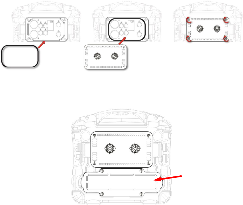
AreaRAE Plus & AreaRAE Pro User’s Guide
86
17.5 Replacing The Sensor Compartment Cover
Before replacing the sensor compartment cover, inspect the large O-ring gasket for damage. If it is
damaged, discard it and use a new one.
1. Place the O-ring gasket in the compartment. (Inspect the O-ring gasket for wear or
damage first. If necessary, replace it.)
2. Press all the sensors firmly in place to ensure they are seated correctly.
3. Set the sensor compartment cover on top of the compartment.
4. Tighten the four screws. Note: Do not overtighten.
17.6 Battery Removal/Replacement
The battery is located in a bay in the lower half of the AreaRAE Plus/Pro’s back.
Changing the AreaRAE Plus/Pro battery pack requires a Philips screwdriver. To replace the AreaRAE
Plus/Pro battery:
1. Turn the instrument off.
2. Remove the filter from the front of the instrument.
3. Place the instrument face-down on a soft surface.
4. Remove the four screws that hold the battery.
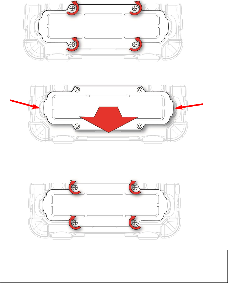
AreaRAE Plus & AreaRAE Pro User’s Guide
87
5. Use your fingers to lift the battery out (there are indents at each end):
6. Slide a new battery into place.
7. Tighten the four screws.
WARNING
To reduce the risk of ignition of hazardous atmospheres, recharge, remove or replace the
battery only in an area known to be non-hazardous! Do not mix old and new batteries or
batteries from different manufacturers.
AreaRAE Plus & AreaRAE Pro User’s Guide
88
17.7 Alkaline Battery Pack
The alkaline battery adapter (part number W01-3007-300) is installed and removed just like the rechargeable
lithium-ion battery. It accepts five D-cell alkaline batteries (use only Duracell MN1300).
To replace the alkaline adapter’s batteries:
1. Remove the four screws holding the adapter.
2. Lift the alkaline battery adapter from the rear of the AreaRAE Plus/Pro.
3. Unscrew the two Philips screws.
AreaRAE Plus & AreaRAE Pro User’s Guide
89
4. Tilt up the cover of the battery compartment and remove it.
5. The five locations for batteries have hook-and-loop fabric strips across them. Unfasten them.
AreaRAE Plus & AreaRAE Pro User’s Guide
90
6. Insert five fresh D-cell alkaline batteries as indicated by the polarity (+/-) markings.
7. Attach the hook-and-loop fabric to secure the batteries in place.
AreaRAE Plus & AreaRAE Pro User’s Guide
91
8. Replace the cover by tilting it so that the two tabs match the slots in the instrument and then
lowering it into place.
9. Replace the two Philips screws.
10. Slide a new battery into place.
11. Tighten the four screws.
IMPORTANT!
Alkaline batteries cannot be recharged. The instrument’s internal circuit detects alkaline battery pack and
will not allow recharging. If you try to charge alkaline batteries installed in the instrument, the display
does not show charging, indicating that it will not charge them.
Do not mix old and new batteries or batteries from different manufacturers.
Note: When replacing alkaline batteries, properly dispose of old ones.
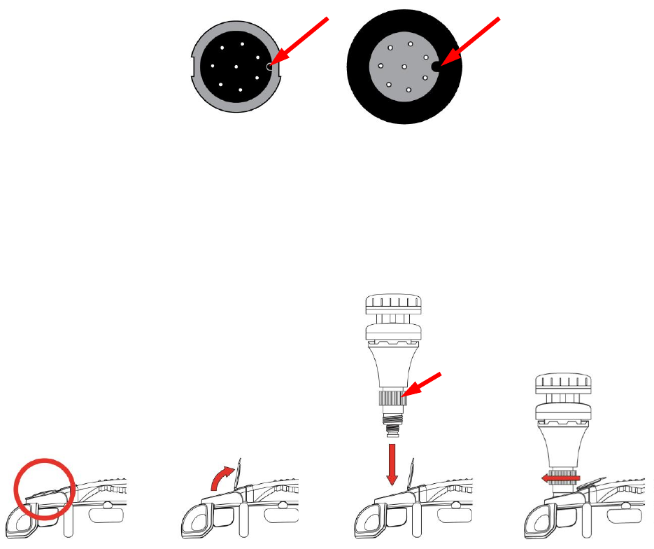
AreaRAE Plus & AreaRAE Pro User’s Guide
92
17.8 RAEMet Meteorological Sensor (Optional)
If your AreaRAE Plus/Pro is equipped with a RAEMet meteorological sensor (P/N: C04-0970-000), it is
typically removed for storage and must be attached before using it.
1. If the AreaRAE Plus/Pro is on, turn it off. (Never attach or remove the RAEMet without first
turning off the instrument’s power.)
2. Lift up the weather-tight rubber cover, located at the end of the handle, to expose the RAEMet
receptacle.
3. Align the RAEMet’s connector plug with the AreaRAE Plus/Pro’s receptacle using the indexing
key and notch as a guide.
4. Press the RAEMet’s base into place, and then turn the locking ring to tighten the connection.
Never force the connector in or out of the receptacle.
5. Tighten the locking ring until the RAEMet sensor is firmly seated. Do not turn the entire
RAEMet sensor.
IMPORTANT!
If the RAEMet and AreaRAE receptacle are not aligned properly, electrical connections will not be made
and the RAEMet sensor will not operate. Also, when the RAEMet sensor is not attached to the
instrument, make sure the cover is securely closed to keep moisture and debris from entering the base.
Note: Keep strong magnets away from the RAEMet sensor. It contains a compass, and strong magnetism
can affect its accuracy.
Locking Ring
Indexing notch in
receptacle
Indexing key in
RAEMet Connector
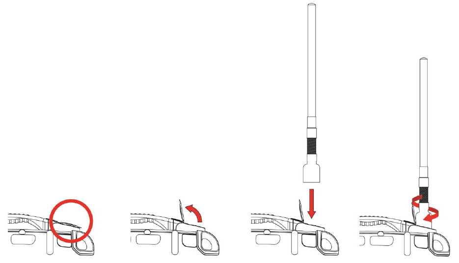
AreaRAE Plus & AreaRAE Pro User’s Guide
93
17.9 Antenna Installation
Attach the antenna by opening the compartment, aligning the antenna, and turning the base of the antenna until it
is snug.
IMPORTANT!
When the antenna is not attached to the instrument, make sure the cover is securely closed to keep
moisture and debris from entering the base.
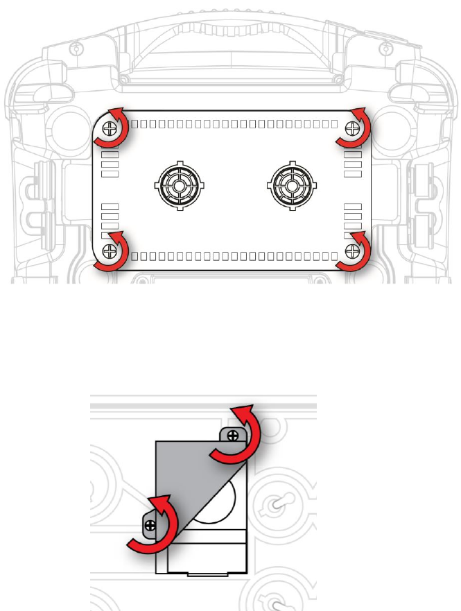
AreaRAE Plus & AreaRAE Pro User’s Guide
94
17.10 Replacing The Pump
If your AreaRAE Plus/Pro’s pump requires replacement, follow these steps.
IMPORTANT! Turn off the instrument and remove the battery before proceeding.
IMPORTANT! Remove the external filter before proceeding.
1. Remove the sensor compartment cover.
2. Turn it upside down and set it on a soft flat surface.
3. The pump assembly is attached to the sensor compartment cover with two Philips screws.
Remove the two screws.
4. Lift off the pump assembly.
5. Pressing down on the gas plate with one hand, disconnect the pump from internal tubing by gently
pulling it out. It has an inlet and outlet that are held in the two holes with rubber O-ring gaskets.
6. Install two new O-ring gaskets (P/N: 430-B081-0H0) in the compartment’s inlet and outlet.
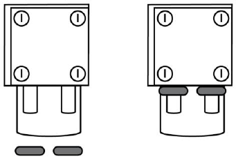
AreaRAE Plus & AreaRAE Pro User’s Guide
95
7. Press a new pump assembly (P/N: W01-3002-000) into place, making sure that both the inlet and
outlet from the pump go through the O-rings into the two holes.
9. Insert and tighten the two screws that attach the bracket to the housing.
10. Replace the cover.
11. Turn on the instrument and check for proper pump operation.
AreaRAE Plus & AreaRAE Pro User’s Guide
96
18 Alarms Overview
The AreaRAE Plus/Pro provides an unmistakable four-way alarm notification system that combines local
alarms on the device with real-time remote wireless alarm notification (if the instrument is equipped
wireless functionality and it is active). Local alarms include audible buzzer alarm, visible alarm via bright
LED lights, and an alarm notification on the display. These can be selectively turned on or off.
18.1 Alarm Signals
During each measurement period, the gas concentration and radiation levels are compared with the
programmed alarm limits for Low, High, TWA, STEL, and other alarms, as applicable. If the
concentration exceeds any of the preset limits, the alarms are activated immediately to warn both the
AreaRAE Plus/Pro user and a remote safety officer (if wireless is enabled) of the alarm condition. In
addition to gas and radiation alarms, other alarms are available.
Furthermore, the AreaRAE Plus/Pro alarms if one or more of the following conditions occurs: battery
voltage low, pump blocked, PID lamp failed, etc.
When the low battery alarm occurs, there may be approximately 15 minutes of operating time remaining. In this
case, it is recommended that you promptly change or charge the battery in a non-hazardous location.
18.2 Changing The Alarm Mode
Your choices are Auto Reset and Latched. A latched alarm stays on until you acknowledge the alarm by
pressing a button. An auto-reset alarm turns off when the condition that set off the alarm is no longer
present (for instance, a high H2S reading that exceeds the preset threshold and triggers an alarm, but then
lowers below that threshold, turning the alarm off).
1. Enter the Alarm Mode sub-menu of the Alarms section under the Programming Menu.
2. Select Auto Reset or Latched by pressing [N/-] to select the mode, and [Y/+] to confirm the
choice.
3. Press [Y/+] to save your selection.
AreaRAE Plus & AreaRAE Pro User’s Guide
97
19 Diagnostic Mode
In Diagnostic Mode, the AreaRAE Plus/Pro provides raw counts for sensor, battery, and other readings,
as well as a list of installed sensors and information about them (expiration date, serial number, etc.).
Most of these screens are useful only to service technicians. Many allow access for changing settings.
Diagnostic Mode can only be accessed at startup time. In Diagnostic Mode, readings are displayed in raw
counts instead of parts per million (ppm) or other units of measure.
19.1 Enter Diagnostic Mode
1. With the instrument turned off, press and hold [Y/+] and [MODE] until the AreaRAE Plus/Pro
starts up.
2. After startup, enter the password when prompted (default is “0000”) and press [MODE].
Once Diagnostic Mode is active, step from screen to screen by pressing [N/-].
19.2 Adjusting Alarm LEDs & Buzzer
The buzzer, green LEDs, red LEDs, and backlight can be turned on or off in Diagnostic mode. In
addition, you can adjust the repetition rate and loudness of the buzzer and the repetition rate and
brightness of the LEDs.
1. Start with the instrument turned off. Hold down the [Y/+] and [MODE] keys until the AreaRAE
Plus/Pro starts.
2. When you see the password screen, input your 4-digit password, and then press [MODE].
3. Once you have entered Diagnostic Mode, press [N/-] until the “Alarm” screen is displayed.
4. Press [MODE] to step through the menu items; press [Y/+] to make a change, and press [N/-] to
advance to the next menu.
Important! When you are done, exit Diagnostic Mode and test the instrument before actual use.
19.3 Adjusting LCD Contrast
The display’s contrast can be adjusted in Diagnostic mode.
1. Start with the instrument turned off. Hold down the [Y/+] and [MODE] keys until the AreaRAE
Plus/Pro starts.
2. When you see the password screen, input your 4-digit password, and then press [MODE].
3. Once you have entered Diagnostic Mode, press [N/-] until the “LCD Contrast” screen is
displayed.
4. Press [Y/+] to increase the value; press [MODE] to decrease the value, and press [N/-] to advance
to the next menu.
Important! When you are done, exit Diagnostic Mode and test the instrument before actual use.
19.4 Pump Stall Threshold Adjustment
Proper setting of the pump stall threshold is necessary so that if there is an obstruction to the inlet, the
pump will stop and the instrument will go into alarm. This prevents unwanted debris or liquid from
entering the pump and causing disruption or damage. The AreaRAE Plus/Pro provides two methods to set
the pump stall threshold: Static and Dynamic.
Note: The Dynamic method uses an algorithm that takes external temperature into consideration for
greater accuracy.
AreaRAE Plus & AreaRAE Pro User’s Guide
98
If it is necessary to set the pump stall threshold, you must enter Diagnostic Mode. Also, regardless of
which method is used, when you are done setting thresholds, exit Diagnostic Mode and test the
instrument before actual use.
19.4.1 Entering Diagnostic Mode To Set The Pump Stall Threshold
5. Start with the instrument turned off. Hold down the [Y/+] and [MODE] keys until the AreaRAE
Plus/Pro starts.
6. When you see the password screen, input your 4-digit password, and then press [MODE].
7. Once you have entered Diagnostic Mode, press [N/-] until the “Pump” screen is displayed.
8. Set the high and low threshold settings for pump stall using the instructions in this section. Press
[MODE] to step through the menu items; press [Y/+] to make a change, and press [N/-] to
advance to the next menu.
19.4.2 Selecting The Pump Stall Threshold Method
At the Pump screen, the settings are shown, including the Pump Speed and Pump Stall Algorithm (which
can be Dynamic or Static).
To change the pump Speed or Stall Algorithm setting:
1. Press [MODE]. Either the pump Speed or the Stall Algorithm is highlighted.
2. To change from “High” to “Low” or “Dynamic” to “Static,” press [Y/+].
Important! The pump Speed must be set to “High” in order to access Dynamic pump stall settings.
Now follow directions to change the pump stall threshold values, using the method that matches your
choice of either Dynamic or Static.
AreaRAE Plus & AreaRAE Pro User’s Guide
99
19.4.3 Setting Pump Stall Threshold Values – Dynamic Method
When the Dynamic pump stall threshold values are shown, you can perform calibration to set the pump
stall values dynamically.
Press [MODE] to begin calibration. This screen is shown, indicating that it is ready:
Press [MODE] to begin calibration. There is a countdown shown in the box. Press [N/-] anytime to abort
the calibration and go back.
AreaRAE Plus & AreaRAE Pro User’s Guide
100
Once the countdown is finished, this message is displayed:
Hold your finger over the inlet, and allow the countdown to proceed. Press [Y/+] anytime to abort and
return to the previous screen.
When the countdown is finished, the main Dynamic pump stall screen is shown.
Dynamic pump stall calibration is complete. You can now exit Diagnostic Mode.
AreaRAE Plus & AreaRAE Pro User’s Guide
101
Important! When you are done setting thresholds, exit Diagnostic Mode and test the instrument before
actual use.
19.4.4 Setting Pump Stall Threshold Values – Static Method
Use the following values for reference when using the Static method to adjust the pump stall threshold
values:
Low Speed
High Speed
Vacuum
≤ -2.5in Hg
≤ -10in Hg
Flow rate
>200 cc/min
>400 cc/min
Idle (I)
100 to 200 counts
150 to 250 counts
Block
(Block-Idle) > 100 counts
(Block-idle) > 100 counts
Stall Setting
(Idle + Block)/2
(Idle + Block)/2
Stall High Threshold Setting – Static Method
In Diagnostic Mode, press the [MODE] key repeatedly until the “Pump” screen is displayed. “High”
should be highlighted. Otherwise, press [Y/+] to select the “High” value.
The Idle value (shown as a value for “I”) should be 150 to 250. Record the value.
Block the inlet, and record the value after it goes up.
The blocked value minus the Idle (Unblocked) value should be greater than 100 counts: (Blocked
value – Unblocked value) > 100.
If it is greater than 100, then the pump is working correctly and tubing leading from the inlet is not
leaking.
To calculate the best High value, first add the Blocked and Unblocked values and divide by 2:
(Blocked value + Unblocked value) / 2 = correct Stall High value.
Press [N/-] to advance to the next Pump screen.
Use the [Y/+] and [N/-] keys to increase or decrease the high value input the results of your
calculation.
Press [MODE] to register that value.
AreaRAE Plus & AreaRAE Pro User’s Guide
102
Verifying the Stall High Setting
Exit Diagnostic Mode. In Normal Mode, with the pump at high speed, block the inlet. The pump should
stall after a few seconds, sending the instrument into alarm. This tells you that the pump’s Stall High
setting is correct.
If the gas inlet is blocked but the pump does not shut down, or the pump shuts down too easily with a
slight blockage, the pump stall threshold value may be set too high or too low.
If the pump does not stall or send the instrument into alarm, then there may be a leak in the gas inlet
or the pump is weak or defective and should be replaced.
Stall Low Threshold Setting - Static
In Diagnostic Mode, press the [MODE] key repeatedly until the “Pump” screen is displayed. “Low”
should be highlighted. Otherwise, press [Y/+] to select the “Low” value.
The Idle (shown as a value for “I”) value should be 100 to 200. Record the value.
Block the inlet, and record the value after it goes up.
The blocked value minus the idle (unblocked) value should be greater than 100 counts:
(Blocked value – Unblocked value) > 100
If it is greater than 100, then the pump is working correctly and tubing leading from the inlet is not
leaking.
To set the Low value, first add the blocked and unblocked values and divide by 2:
(Blocked value + Unblocked value) / 2 = correct Stall Low value
Then, using the [Y/+] and [N/-] keys, set the Stall Low value to this number.
Verifying the Stall Low Setting - Static
Exit Diagnostic Mode. In Normal Mode, block the inlet. The pump should stall after a few seconds,
sending the instrument into alarm. This tells you that the pump’s Low setting is correct.
If the gas inlet is blocked but the pump does not shut down, or the pump shuts down too easily with a
slight blockage, the pump stall threshold value may be set too high or too low.
If the pump does not stall and send the instrument into alarm, then there may be a leak in the gas inlet
or the pump is weak or defective and should be replaced.
Important! When you are done setting thresholds, exit Diagnostic Mode and test the instrument before
actual use.
19.5 Exit Diagnostic Mode
Hold [MODE] until the AreaRAE Plus/Pro shuts off. When you start it up again, it is in normal operating
mode.

AreaRAE Plus & AreaRAE Pro User’s Guide
103
19.6 Alarm Signal Summary
19.6.1 Hygiene Mode
Alarm Type
Buzzer & LED
Display
Reading
Backlight
Priority
Fail
3 beeps/sec
“Lamp” at PID location
“Off” at LEL location
Blinking
reading
Fail
Highest
Pump
3 beeps/sec
Blinking pump symbol
Reading
Pump
Fail
3 beeps/sec
“Lamp” at PID location
“Off” at LEL location
Blinking
reading
On
Pump
3 beeps/sec
Blinking pump symbol
Reading
On
Max
3 beeps/sec
“Max” at sensor location
Blinking
reading
On
Over Range
3 beeps/sec
“Over” at sensor location
Blinking
9999
On
High
3 beeps/sec
“High” at sensor location
Reading
On
Low
2 beeps/sec
“Low” at sensor location
Reading
On
Negative
1 beep/sec
“Neg” at sensor location
0
On
STEL
1 beep/sec
“STEL” at sensor
location
Reading
On
TWA
1 beep/sec
“TWA” at sensor
location
Reading
On
Calibration
Fail
1 beep/sec
“Cal” at sensor location
Reading
On
Bump Fail
1 beep/sec
“Bump” at sensor location
Reading
On
Datalog Full
1 beep/sec
Blinking datalog symbol
Reading
On
Calibration
Required
-
“Full” Bottle symbol
Reading
-
Bump
Required
-
“Empty” Bottle symbol
Reading
-
Battery
1 beep/min
Blinking battery symbol
Reading
Stays as
is
Comfort
Beep
1 beep/min
no LED flash
-
Reading
-
Lowest
Notes
“Negative” means that the true sensor reading is below zero, even though a zero reading is
shown for the sensor.

AreaRAE Plus & AreaRAE Pro User’s Guide
104
19.6.2 General Alarms
Message
Condition
Alarm Indications
HIGH
Gas exceeds “High Alarm” limit
3 beeps/flashes per second
OVR
Gas exceeds sensor’s measurement range
3 beeps/flashes per second
MAX
Gas exceeds electronic circuit’s maximum
range
3 beeps/flashes per second
LOW
Gas exceeds “Low Alarm” limit*
2 beeps/flashes per second
TWA
Gas exceeds “TWA” limit
1 Beep/flash per second
STEL
Gas exceeds “STEL” limit
1 Beep/flash per second
Crossed pump
icon flashes
Inlet blocked or pump failure
3 beeps/flashes per second
“Lamp”
flashes
PID lamp failure
3 beeps/flashes per second
Empty battery
icon flashes
Low battery
1 flash, 1 beep per minute
CAL
Calibration failed, or needs calibration
1 beep/flash per second
NEG
True sensor reading is below zero, even
though a zero reading is shown for the
sensor.
1 beep/flash per second
* For oxygen, “low alarm limit” means a concentration is lower than the low alarm limit.

AreaRAE Plus & AreaRAE Pro User’s Guide
105
20 Troubleshooting
Problem
Possible Reasons & Solutions
Cannot turn on power after
charging the battery
Reasons: Defective charging circuit. Defective battery.
Solutions: Replace battery or charger. Try charging battery
again.
Lost password
Solutions: Call Technical Support at +1 408-952-8461
or toll-free at +1 888-723-4800
Buzzer, LED lights
inoperative
Reasons: Buzzer and/or other alarms disabled.
Bad buzzer, LED lights, or PCB.
Solutions: Check under “Alarm Settings” in
Programming Mode that buzzer and/or other
alarms are not turned off.
Call authorized service center.
“Lamp” message when
power on. Lamp alarm.
Reasons: Low ion concentration inside PID lamp
especially in cold environment when first
powered on. Defective PID lamp or defective
circuit.
Solutions: Turn the unit off and back on. Replace UV
lamp.
Pump failed message.
Pump alarm.
Reasons: Inlet probe blocked. Direct connection to a
gas outlet while the gas value is turned off.
Water trap filter sucks in water. Water trap
filter too dirty. Water condensed along the
inlet probe. Bad pump or pump circuit.
Solutions: Remove the blocking objects and then press
[Y/+] key to reset the pump alarm. Replace
contaminated water trap filter. Be careful not
to allow water condensation inside the unit.
Replace the pump.
If you need replacement parts, a list is available online:
www.raesystems.com

AreaRAE Plus & AreaRAE Pro User’s Guide
106
21 Specifications
Dimensions
12.6″ x 12.4″ x 6.3″ (322 mm x 315 mm x 160 mm) with boot
Weight
13.67 lbs (6.3 kg)
Gas Sensor Slots
7 total; see Sensor list on this page
Additional Sensors*
Gamma, RAEMet (wind speed, wind direction, temperature, humidity)
GPS
Installed at factory
Battery
Rechargeable 7.2V/10AH Li-ion battery pack with built-in charger
Alkaline adapter with 5 D-size batteries
Battery Charging Time
<10 hrs
Operating Hours
Approximately 16 hours with wireless connectivity, GPS, and all sensors
operational
Power input
AC adapter with Input 110-240 V AC
Display
Large 240x320 pixel LCD display
2.5″ x 3.34″ (63.59 mm x 84.79 mm)
Keypads
3 operation and programming keys
Alarms
High/Low limits for gases and radiation detectors, STEL, TWA limits for
EC sensors, low battery, sensor, or pump failure
Visible Alarm
Bright LED, 360-degree view
Audible Alarm
Dual buzzers: 108 dB @ 1 m
Data logging
Continuous datalogging (90 days for 12 gas sensors and GPS at 1-minute
intervals, continuously)
Data Storage
24M bytes (memory-full action: stop when full or wrap-around)
Data Interval
User-configurable from 1 to 3,600 sec
Wireless
Long Range: ISM License-free 900 to 928 MHz or 2.4GHz
Optional WiFi
Secondary: Mesh Network
FCC Compliance
FCC Part 15
Communication
Communicates to ProRAE Studio via USB cable to PC;
Wireless data and alarm status transmission via Wi-Fi or ISM modem;
Acts as gateway to connect up to 8 remote Mesh-module equipped
instruments
Safety Certification
Class I, Division 2 Groups A, B, C, D
ATEX Zone 2 (II 3G Ex nA [ic Gc] IIC T4 Gc)
IECEx (Ex n IIC T4 Gc)
Ex n IIC T4 Gc (China)
Sampling Pump
Built-in pump, typical flow rate 450 cc/min
Temperature
-20° C to 50° C (-4° F to 122° F)
Humidity
0% to 95% relative humidity (non-condensing)
Ingress Protection (IP)
IP-65 (third-party tested)

AreaRAE Plus & AreaRAE Pro User’s Guide
107
Languages
Chinese, Dutch, English, French, German, Italian, Portuguese, Russian,
Spanish
Warranty
• Two years on non-consumable components and catalytic LEL, CO, H2S,
and O2 sensors
• Six months for 9.8eV lamp PID sensor
• One year on all other sensors, battery, and other consumable parts
* Optional sensors. Gamma sensor only available on AreaRAE Plus/Pro.
Specifications are subject to change.

AreaRAE Plus & AreaRAE Pro User’s Guide
108
Sensor Specifications
Radiation Sensor
Range
Resolution
Gamma
0 to 20,000 µRem/h
1 µRem/h
PID Sensors for VOC
Range
Resolution
4R+; 10.6eV* ppb
0 to 2,000 ppm
10 ppb
4R+ 9.8 eV
0 to 2,000 ppm
0.1 ppm
7R+ 10.6 eV* ppb
0 to 2,000 ppm
10 ppb
7R+ 10.6 eV (Extended Range)
0 to 5,000 ppm
0.1 ppm
Combustible Sensors
Range
Resolution
4R+ LEL
0 to 100% LEL
1% LEL
Electrochemical Sensors
Range
Resolution
Ammonia
0 to 100 ppm
1 ppm
Carbon Monoxide
0 to 500 ppm
1 ppm
Carbon Monoxide
0 to 2,000 ppm
10 ppm
Carbon Monoxide
(H2-comp)
0 to 2,000 ppm
10 ppm
Chlorine
0 to 50 ppm
0.1 ppm
Chlorine dioxide
0 to 1 ppm
0.03 ppm
Ethylene Oxide ETO-A
0 to 100 ppm
0.5 ppm
Ethylene Oxide ETO-B
0 to 10 ppm
0.1 ppm
Ethylene Oxide ETO-C
0 to 500 ppm
10 ppm
Hydrogen
0 to 2,000 ppm
2 ppm
Hydrogen Chloride
0 to 30 ppm
1 ppm
Hydrogen Cyanide
0 to 50 ppm
0.5 ppm
Hydrogen Fluoride
0 to 10 ppm
0.1 ppm
Hydrogen Sulfide
0 to 100 ppm
0.1 ppm
Hydrogen Sulfide extended
0 to 1,000 ppm
0.1 ppm
Oxygen
0 to 30%
0.1%
Sulfur Dioxide
0 to 20 ppm
0.1 ppm
Nitric Oxide
0 to 250 ppm
1 ppm
Nitrogen Dioxide
0 to 50 ppm
0.1 ppm
Phosphine
0 to 5 ppm
0.1 ppm
Specifications are subject to change without notice.

AreaRAE Plus & AreaRAE Pro User’s Guide
109
LEL Range, Resolution & Response Time
LEL 0-100% 1 % 15 sec
LEL Correction Factors
Compound
100% LEL
(Vol %)
LEL CF*
Acetone
2.5
1.9
Ammonia
15
1.0
Benzene
1.2
2.1
Butane, n-
1.9
1.9
Carbon monoxide
12.5
1.3
Cyclohexane
1.3
2.1
Ethanol
3.3
1.8
Ethyl acetate
2
2.4
Gasoline
1.3
2.6
Heptane, n-
1.1
2.5
Hexane, n-
1.1
2.1
Hydrogen
4
1.0
Isobutene
(Isobutylene)
1.8
1.6
Isopropanol
2
2.2
Methane
5
1.0
Methanol
6
1.6
Methyl ethyl ketone
4.5
2.2
Octane, n-
1
2.7
Propane
2.1
1.4
Propene
2
1.6
Toluene
1.1
2.4
Turpentine
0.8
3.0
Note: Values in bold type are confirmed with RAE Systems by Honeywell instruments. Others, shown in
italic, are calculated from diffusion models.
* These figures are for guidance only and are rounded to the nearest 5%. For the most accurate
measurements, the instrument should be calibrated with the gas under investigation. See RAE Systems
Technical Note TN-156 for more details and other compounds.
Caution:
Refer to RAE Systems Technical Note TN-144 for LEL sensor poisoning.

AreaRAE Plus & AreaRAE Pro User’s Guide
110
Year Of Manufacture
To identify the year of manufacture, refer to the serial number of the instrument.
The second to last digit in the serial number indicates the year of manufacture. For example, “M”
indicates the manufacturing year is 2010.
First digit
Year
J
2008
K
2009
M
2010
N
2011
P
2012
Q
2013
R
2014
S
2015
T
2016
U
2017
V
2018
W
2019
AreaRAE Plus & AreaRAE Pro User’s Guide
111
Controlled Part of Manual
WARNINGS
Read Before Operating
This manual must be carefully read by all individuals who have or will have the responsibility of using,
maintaining, or servicing this product. The product will perform as designed only if it is used, maintained,
and serviced in accordance with the manufacturer’s instructions.
CAUTION!
Never operate the monitor when the cover is removed. Remove the monitor rear cover or battery only in
an area known to be non-hazardous.
ANY RAPID UP-SCALE READING FOLLOWED BY A DECLINING OR ERRATIC READING
MAY INDICATE A GAS CONCENTRATION BEYOND UPPER SCALE LIMIT, WHICH MAY
BE HAZARDOUS.
TOUTE LECTURE RAPIDE ET POSITIVE, SUIVIE D’UNE BAISSE SUBITE AU ERRATIQUE
DE LA VALEUR, PEUT INDIQUER UNE CONCENTRATION DE GAZ HORS GAMME DE
DÉTECTION QUI PEUT ÊTRE DANGEREUSE
ONLY THE COMBUSTIBLE GAS DETECTION PORTION OF THIS INSTRUMENT HAS
BEEN ASSESSED FOR PERFORMANCE.
UNIQUMENT, LA PORTION POUR DÉTECTOR LES GAZ COMBUSTIBLES DE CET
INSTRUMENT A ÉTÉ ÉVALUÉE.
CAUTION: BEFORE EACH DAY’S USAGE, SENSITIVITY OF THE LEL SENSOR MUST BE
TESTED ON A KNOWN CONCENTRATION OF METHANE GAS EQUIVALENT TO 20 TO 50%
OF FULL-SCALE CONCENTRATION. ACCURACY MUST BE WITHIN 0 AND +20% OF
ACTUAL. ACCURACY MAY BE CORRECTED BY CALIBRATION PROCEDURE.
ATTENTION: AVANT CHAQUE UTILISATION JOURNALIERE, VERIFIER LA SENSIBILITE
DU CAPTEUR DE LIE AVEC UNE CONCENTRATION CONNUE DE METHANE EQUIVALENTE
DE 20 A 50% DE LA PLEINE ECHELLE. LA PRECISION DOIT ETRE COMPRISE ENTRE 0 ET
20% DE LA VALEUR VRAIE ET PEUT ETRE CORRIGEE PAR UNE PROCEDURE
D’ETALONNAGE.
CAUTION: HIGH OFF-SCALE READINGS MAY INDICATE AN EXPLOSIVE
CONCENTRATION.
ATTENTION: DES LECTURES HAUTES ET HORS D’ECHELLE PEUVENT INDIQUER DES
CONCENTRATIONS DE GAZ INFLAMMABLES
CAUTION: SUBSTITUTION OF COMPONENTS MAY IMPAIR INTRINSIC SAFETY.
Note: Users are recommended to refer to ISA-RP12.13, Part II-1987 for general information on
installation, operation, and maintenance of combustible gas detection instruments.
The AreaRAE2 multi-gas detector must be calibrated if it does not pass a bump test, or at least once every
180 days, depending on use and sensor exposure to poisons and contaminants.
AreaRAE Plus & AreaRAE Pro User’s Guide
112
CAUTION!
TheAreaRAE, PGM-65XX, shall only be charged using a charger specifically supplied for use with the
unit with a maximum output voltage of 17V.
Use of non-RAE Systems components will void the warranty and can compromise the safe performance
of this product.
PGM-65XX Marking
The PGM-65XX is certified according to the IECEx scheme, ATEX and CSA for US and Canada under
the non-sparking safety method of protection.
The PGM-65XX is marked with the following information:
RAE SYSTEMS
3775 N. 1st. St., San Jose
CA 95134, USA
Type PGM-65XX.
Serial No/barcode: XXXX-XXXX-XX
IECEx XXX15.XXXX
Ex ic nA [ic] IIC T4 Gc
XXX 15 ATEX XXXX
II 3G Ex ic nA [ic] IIC T4 Gc
Cl.I Dv 2, Grps A,B,C,D
T-Code T4.
C22.2 No.152-M1984
ANSI/ISA-12.13.01-2013
-20º C < Tamb < +50º C;
Um:17V
RAEMet connection:Uo: 5.2V, Po: 0.788W, Lo:198μH, Co:1000μF
SSRelay connection: Ui: 24V, Ii:250mA
Battery pack: W01-3007-000
CAUTION: READ AND UNDERSTAND INSTRUCTION MANUAL BEFORE OPERATING OR
SERVICING
ATTENTION: LIRE ET COMPRENDRE MANUEL D’INSTRUCTIONS AVANT D’UTILISER OU
SERVICE
Operation Area and Conditions
Hazardous Areas Classified by Zones
PGM-65XX are intended to be used in hazardous areas classified zone 2 within the temperature range of
-20ºC to +50ºC, where gases of explosion groups IIA, IIB or IIC and T4 may be present.
Hazardous Areas classified by Divisions
PGM-65XX is intended to be used in hazardous areas classified for Class I Div. 2, within the
temperature range of -20º C to +50º C, where gases of explosion groups A, B, C or D and temperature
code T4 may be present.
AreaRAE Plus & AreaRAE Pro User’s Guide
113
Instruction For Safe Use
WARNING: Read and understand instruction manual before operation or servicing.
AVERTISSEMENT: Lisez et comprenez le manual d’instructions avant d’utiliser ou d'effectuer
l'entretien.
WARNIING: Substitution of components may impact safety.
AVERTISSEMENT: La substitution de composants peut compromettre la sécurité.
WARNING: To prevent ignition of a hazardous atmosphere, batteries must only be charged in an area
known to be non-hazardous area in the ambient temperature range 0° C ≤ Tamb ≤ 40° C. Use only
approved charger.
AVERTISSEMENT: Afin de prevenir l’inflammation d’atmosphères dangereuse, ne charger le jeu de
batteries que dans des emplacement designés non dangereux a temperature ambiante 0°C ≤ Tamb ≤ 40°C
Utilisez uniquement un chargeur approuvé.
WARNING: As a condition of certification, connection may not be made to the communication port
when the Gas Detector is in the hazardous location unless the area is known not to be hazardous.
AVERTISSEMENT: Comme condition de la certification, un connexion filaire ne peut pas être faite via
le port de communication lorsque le détecteur de gaz est dans la zone dangereuse à moins que la zone soit
connue pour ne pas être dangereuse.
WARNING: Li-Ion rechargeable battery: Only use approved battery pack: W01-3007-000/
AVERTISSEMENT: Batterie rechargeable Li-Ion: Utilisez uniquement des approuvé : W01-3007-000
WARNING: For the battery cassette for primary batteries only use 5 new D-size alkaline batteries. Do
not mix old and new primary batteries or batteries from different manufacturers, in the primary battery
cassette.
AVERTISSEMENT: Pour la cassette des batteries primaires utilisent seulement 5 nouvelles piles
alcalines de type D (Duracell MN1300). Ne pas mélanger des piles primaires anciennes et nouvelles ou
de différents fabricants, dans la cassette de la batterie primaire.
Only use RAE Systems charger for PGM-65XX with a maximum output voltage of 17V.
Use In Hazardous Areas
Equipment which is intended for use in explosive atmospheres and which has been assessed and certified
according to international regulations may be used only under specified conditions. The components may
not be modified in any way.
The appropriate regulations for service and repair must be properly observed during such activities.
PGM-65XX contains a connector for mounting of a wind sensor – RAEMet. This connector havs a set of
entity parameters that match the input entity parameters of RAEMet:
Uo: 5.2V; Po: 0.788W; Lo: 198μH; Co: 1000μF
The solid-state relay connection is supplied with the following entity parameters, which must be complied
with for external connections:
Ui: 24V; Ii: 250mA

AreaRAE Plus & AreaRAE Pro User’s Guide
114
Year of manufacture
To identify the year and month of manufacture, refer to the two digit marking placed adjacent to the serial
number on the instrument label according to the following table:
Year
First digit
Year code
Month
Second digit
Month code
2014
R
January
1
2015
S
February
2
2016
T
March
3
2017
U
April
4
2018
V
May
5
2019
W
June
6
2020
A
July
7
2021
B
August
8
2022
C
September
9
2023
D
October
A
2024
E
November
B
2025
F
December
C
E.g.: “RA” indicates that the monitor was manufactured in the month of October in the year 2014.
Turning the PGM-65XX On
With the instrument turned off, press and hold the [MODE] key for 3 seconds, and then release. The
startup process begins. The instrument performs a set of self-tests, while displaying information about
instrument’s settings, configuration, due dates for calibration and bump tests, etc.
When the startup completes, the PGM-65XX displays its normal measurement screen with instantaneous
readings and other information.
Pausing To View Screens During Startup
Press the [MODE] button anytime during the startup sequence to pause the progression. This allows you
to view the information for as long as you like. To resume the progression, press [MODE] again. Even if
you pause the progression of screens, the startup process is not interrupted.
Note: To speed up the startup time, the number of screens shown on startup can be reduced by enabling
the Fast Startup option under Programming/Monitor.
Then the PGM-65XX’s main reading screen appears. It displays instantaneous readings similar to the
following screen (depending on the sensors installed) and is ready for use.
Note: If the battery is completely empty, then the display briefly shows the message “Battery Fully
Discharged,” and the PGM-65XX shuts off. You should charge the battery or replace it with a fully
charged battery before turning it on again.
Turning the PGM-65XX Off
Press and hold [MODE]. A 5-second countdown to shutoff begins. You must hold your finger on the key
for the entire shutoff process.

AreaRAE Plus & AreaRAE Pro User’s Guide
115
Alarm Signals
The instrument is equipped with audible, visible, and vibration alarms. During its normal operation, the
PGM-65XX compares gas concentrations to the programmed alarm limits for Low, High, TWA and
STEL alarms. If the concentration exceeds any of the preset limits, the loud buzzer, and red flashing
LEDs are activated immediately to warn of the alarm condition. In addition, the PGM-65XX alarms if the
battery voltage is low, pump is blocked, etc.
When a low-battery alarm occurs, there may be approximately 20 to 30 minutes of operating time
remaining. However, it is recommended that you promptly change or charge the battery in a non-
hazardous location.
Alarms Summary
Testing Alarms
Under normal operation mode and non-alarm conditions, the audible, visual, and vibration alarms can be
tested at any time by pressing the [Y/+] key.
Programming Menu
Programming Menu is used to change instrument configuration settings can be entered from Normal
Mode by pressing and holding [MODE] and [N/-] together for more than 3 seconds and supplying a
password when prompted.
Message
Condition
Alarm Indications
HIGH
Gas exceeds “High Alarm” limit
3 beeps/flashes per second
OVR
Gas exceeds sensor’s measurement range
3 beeps/flashes per second
MAX
Gas exceeds electronic circuit’s maximum
range
3 beeps/flashes per second
LOW
Gas exceeds “Low Alarm” limit*
2 beeps/flashes per second
TWA
Gas exceeds “TWA” limit
1 Beep/flash per second
STEL
Gas exceeds “STEL” limit
1 Beep/flash per second
Crossed pump
icon flashes
Inlet blocked or pump failure
3 beeps/flashes per second
“Lamp”
flashes
PID lamp failure
3 beeps/flashes per second
Empty battery
icon flashes
Low battery
1 flash, 1 beep per minute
CAL
Calibration failed, or needs calibration
1 beep/flash per second
NEG
True sensor reading is below zero, even
though a zero reading is shown for the
sensor.
1 beep/flash per second
* For oxygen, “low alarm limit” means a concentration is lower than the low alarm limit.

AreaRAE Plus & AreaRAE Pro User’s Guide
116
Alarm Menus
Use this menu to change high, low, STEL, and TWA alarm limits - the points at which alarms are
triggered. The Alarms menu also allows changing alarm mode (latched or automatic reset) and alarm
output methods (combinations of light and buzzer alarm indications).
Changing Alarm Mode
You can program the AreaRAE Plus/Pro so that there are two ways to shut off an alarm:
Auto Reset
When the alarm condition is no longer present, the alarm stops automatically.
Latch
You must manually turn off an alarm when one is triggered. The latched setting only
controls alarms for High Alarm, Low Alarm, STEL Alarm, and TWA Alarm.
Bump Testing and Calibration
RAE Systems recommends that a bump test be conducted prior to each day’s use. The purpose of a bump
test is to ensure that the instrument’s sensors respond to gas and all the alarms are enabled and functional.
The PGM-65XX multi-gas detector must be calibrated if it does not pass a bump test when a new
sensor is installed, after sensor maintenance has been performed, or at least once every 180 days,
depending on use and sensor exposure to poisons and contaminants.
Calibration and bump test intervals and procedures may vary due to national legislation and
company policy.
During a bump test, the instrument makes a pass/fail decision based on sensor performance, but the user
still has the responsibility to make sure all the alarms are enabled and functional.
Each bump test or calibration option shows a countdown followed by sensor reading and pass/fail results.
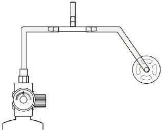
AreaRAE Plus & AreaRAE Pro User’s Guide
117
Bump Testing
A bump test can be performed on an individual sensor (Single Sensor Bump) or a group of sensors (Multi
Sensor Bump) combined into Multi Cal. Select. The same gas is used for a bump test as for calibration.
Typically, two cylinders of calibration gas are needed to perform a bump test or calibration on an
instrument with a PID sensor and electrochemical and LEL sensors. This may require one gas cylinder
with Isobutylene or another VOC test gas to test the PID sensor, and another with a 4-gas mix to test
electrochemical (such as CO, H2S, and O2) and LEL sensors. As with calibration, the instrument
intelligently splits the process into two consecutive steps: first, the wizard prompts for testing
electrochemical and LEL sensors, and then it tests the PID sensor.
For a manual bump test, a constant-flow regulator producing 0.75 to 1 liters per minute should be used.
Attach one end of a “T” using Teflon tubing to the filter on the PGM-65XX inlet. (You can use RAE Systems
P/N: W01-3003-000).
Teflon tubing must be used to test or calibrate the PID sensor. Follow the steps described here to perform
a manual bump test:
1. Turn on your PGM-65XX by pressing and holding [MODE] (the middle button) and allow the
instrument to boot up fully until the main measurement screen with sensor names and readings is
shown.
IMPORTANT!
Make sure all of the instrument’s sensors have warmed up before performing the bump test. The
instrument will take the time to warm up the sensors prior to enabling access to bump test menus.
You can tell a sensor has warmed up if you see a reading next to it name on the display. If it has not
warmed up, you see three dashes (“---”) next to it.
2. Enter the Bump Test menu. It is accessible either through Programming Menu.
3. Connect the PGM-65XX to the calibration gas. Turn on the gas to initiate flow.
4. Press [Y/+] to start the bump test. While the bump test is being performed, the readings for each
sensor are shown. Once the bump test completes, pass/fail test results and readings are shown for
each sensor.
Note: If a PID or other sensors are installed in the instrument require a dedicated cylinder of gas
to calibrate, the instrument will prompt for calibrating such sensors at this point.
5. If a PID or other sensors installed in the instrument require a dedicated gas cylinder to calibrate,
the instrument will prompt to calibrate such sensors at this point. Disconnect the gas cylinder and
connect the next (for example, 10 ppm Isobutylene for a 4R+ ppb PID and the next gas should be
100 ppm; 100 ppm for 7R+ PID, and the next gas 1000 ppm).
AreaRAE Plus & AreaRAE Pro User’s Guide
118
6. Press “OK” to proceed to the PID sensor test. Turn on the gas and press Start ([Y/+] button).
While the bump test is being performed, PID sensor readings are shown. Once the bump test
completes, pass/fail test results and readings are shown for the PID sensor.
Note: If other installed sensors require a dedicated cylinder of gas to calibrate, the instrument
prompts for calibrating these sensors at this point.
IMPORTANT!
If one or more sensors fails a bump test, be sure to calibrate those sensors.
7. The bump test is now complete. Press Exit to return to the main measurement screen.
8. Now perform a manual alarms test.
If all the alarms and all sensors have passed and no sensor is due for a calibration, the instrument is now
ready for use.
Note: When a manual bump test is performed, the readings shown are in the equivalent units of the
calibration gas, and not the measurement gas (if different).
Zero Calibration
The instrument should be zero calibrated in clean ambient air with 20.9% oxygen. A zero calibration
should precede a span calibration.
IMPORTANT! The parts-per-billion PID sensor for volatile organic compounds (VOCs) should not be
zeroed in fresh air. VOCs are normally present in ambient air, so zeroing the sensor in ambient air will
not allow for a true zero to be set. The parts-per-billion PID sensor should be zeroed with ambient air
using a charcoal filter or a VOC zeroing tube.
Fresh Air Calibration
This procedure determines zero points of most sensors. The PGM-65XX should be zero-calibrated in clean
air with 20.9% oxygen or with a cylinder of clean zero air.
At the Calibration menu, select “Fresh Air” by pressing [Y/+] once to enter fresh air calibration.
After a timer countdown, the zero calibration is done. The LCD displays the sensor names and tells you
whether each calibration passed or failed, followed by the sensor readings.
Note: You can abort the calibration at any time during the countdown by pressing [N/-].
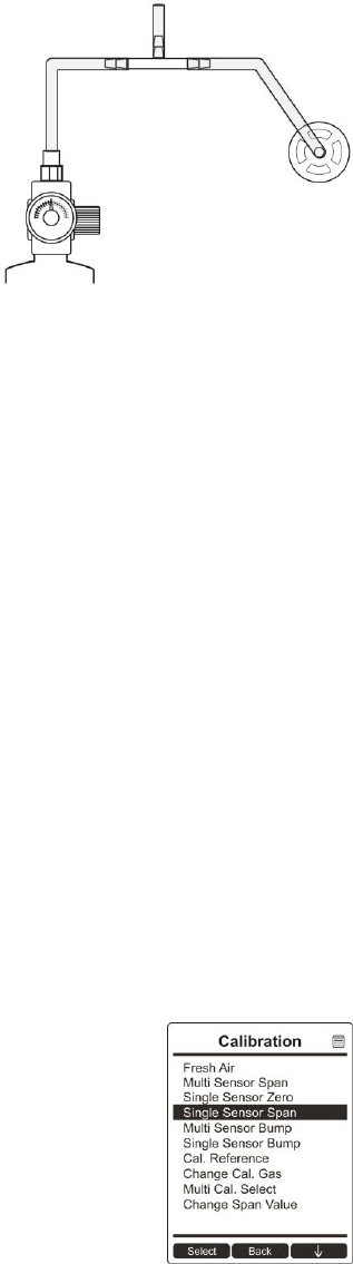
AreaRAE Plus & AreaRAE Pro User’s Guide
119
Multi-Sensor Span Calibration
This lets you perform a span calibration on multiple sensors simultaneously. It requires using the
appropriate span gas and that the concentration labeled on the gas cylinder matches the concentration
programmed in the PGM-65XX.
For a multi-sensor span calibration, a constant-flow regulator producing 0.75 to 1 liters per minute should
be used. Attach one end of a “T” using Teflon tubing to the filter on the PGM-65XX inlet. (You can use RAE
Systems P/N: W01-3003-000).
Teflon tubing must be used to test or calibrate the PID sensor. Follow the steps described here to perform
a multi-sensor span calibration:
1. Attach the “T” tube and connect gas to the PGM-65XX.
2. Start the flow of gas and then either press [Y/+] to begin calibration or wait for calibration to start
automatically once the sensor “senses” the gas. A countdown screen is shown. You can abort the
calibration at any time during the countdown by pressing [N/-].
If the calibration reaches its conclusion, it shows the sensor names and tells you whether the calibration
passed or failed, followed by the sensor readings.
Note: If there are other sensors to be calibrated at this stage, the screens will guide you through the
process.
Single-Sensor Span Calibration
To perform span calibration of an individual sensor, follow these steps:
1. At the Calibration Menu, select “Single Sensor Span.”
2. Select a sensor from the list.
3. Connect the “T” tube and connect it to a source of calibration gas.
4. Verify that the displayed calibration value meets the concentration label on the gas cylinder.
5. Start the flow of calibration gas.

AreaRAE Plus & AreaRAE Pro User’s Guide
120
6. Press [Y/+] to start calibrating. You can abort the calibration at any time during the countdown by
pressing [N/-].
After a timer countdown, the span calibration is done. The LCD will display whether the calibration was
successful and the reading for that calibration gas.
Note: If the sensor calibration fails, try again. If calibration fails repeatedly, the sensor(s) should be
replaced. Replace the sensor.
WARNING: Do not replace sensors in hazardous locations.
Battery Replacement
The battery (W01-3007-000) is located in a bay in the lower half of the PGM-65XX’s back. Changing the
PGM-65XX battery pack requires a Philips screwdriver. To replace the battery:
1. Turn the instrument off.
2. Remove the filter from the front of the instrument.
3. Place the instrument face-down on a soft surface.
4. Remove the four screws that hold the battery.
5. Use your fingers to lift the battery out (there are indents at each end).
6. Slide a new battery into place.
7. Tighten the four screws.

AreaRAE Plus & AreaRAE Pro User’s Guide
121
Troubleshooting
Problem
Possible Reasons & Solutions
Cannot turn on power after
charging the battery
Reasons: Defective charging circuit. Defective battery.
Solutions: Replace battery or charger. Try charging battery
again.
Lost password
Solutions: Call Technical Support at +1 408-952-8461
or toll-free at +1 888-723-4800
Buzzer, LED lights
inoperative
Reasons: Buzzer and/or other alarms disabled.
Bad buzzer, LED lights, or PCB.
Solutions: Check under “Alarm Settings” in
Programming Mode that buzzer and/or other
alarms are not turned off.
Call authorized service center.
“Lamp” message when
power on. Lamp alarm.
Reasons: Low ion concentration inside PID lamp
especially in cold environment when first
powered on. Defective PID lamp or defective
circuit.
Solutions: Turn the unit off and back on. Replace UV
lamp.
Pump failed message.
Pump alarm.
Reasons: Inlet probe blocked. Direct connection to a
gas outlet while the gas value is turned off.
Water trap filter sucks in water. Water trap
filter too dirty. Water condensed along the
inlet probe. Bad pump or pump circuit.
Solutions: Remove the blocking objects and then press
[Y/+] key to reset the pump alarm. Replace
contaminated water trap filter. Be careful not
to allow water condensation inside the unit.
Replace the pump.
The list of replacement parts is available online at www.raesystems.com.
AreaRAE Plus & AreaRAE Pro User’s Guide
122
22 Technical Support
To contact RAE Systems Technical Support Team:
Monday through Friday, 7:00AM to 5:00PM Pacific (US) Time
Phone (toll-free): +1 888-723-4800
Phone: +1 408-952-8461
E-mail: RAE-tech@honeywell.com
Web Site: www.raesystems.com, www.honeywellanalytics.com
Outside the Americas:
E-Mail: HAexpert@honeywell.com
Honeywell Analytics Ltd.
4 Stinsford Road
Nuffield Industrial Estate
Poole, Dorset, BH17 0RZ
United Kingdom
Tel: +44 (0) 1202 645 544
Fax: +44 (0) 1202 645 555
Honeywell Analytics
ZAC Athélia 4 – 375 avenue du Mistral
Bât B, Expace Mistral
13600 La Ciotat
France
Tel: +33 (0) 4 42 98 17 75
Fax: +33 (0) 4 42 71 97 05
Honeywell Analytics
Elsenheimerstrasse 43
80687 München
Germany
Tel: +49 89 791 92 20
Fax: +49 89 791 92 43
Honeywell Analytics
P.O. Box-45595
6th Street
Musaffah Industrial Area
Abu Dhabi
UAE
Tel: +971 2 554 6672
Fax: +971 2 554 6672
AreaRAE Plus & AreaRAE Pro User’s Guide
123
23 RAE Systems by Honeywell Contacts
RAE Systems by Honeywell
World Headquarters
3775 N. First St.
San Jose, CA 95134-1708 USA
Phone: +1 408.952.8200
Fax: +1 408.952.8480
WORLDWIDE SALES OFFICES
USA/Canada: 1.877.723.2878
Europe: +800.333.222.44/+41.44.943.4380
Middle East: +971.4.450.5852
China: +86.10.5885.8788-3000
Asia Pacific: +852.2669.0828

RAE Systems by Honeywell
3775 N. First St.
San Jose, CA 95134-1708 USA
Phone: 408.952.8200
Fax: 408.952.8480
E-mail (technical support): RAE-tech@honeywell.com
Web Site: www.raesystems.com
WORLDWIDE SALES OFFICES
USA/Canada 1.877.723.2878
Europe +800.333.222.44/+41.44.943.4380
Middle East +971.4.450.5852
China +86.10.5885.8788-3000
Asia Pacific +852.2669.0828
Rev A
July 2016
P/N: W01-4001-000