RAE Systems RM900 RAEmesh Radio (RM900) User Manual SU3RM900
RAE Systems, Inc RAEmesh Radio (RM900) SU3RM900
UserManual.wiki
>
RAE Systems
>
RM900 User Manual
User Manual
Navigation menu
Upload a User Manual
Namespaces
Wiki Guide
HTML
PDF
Info
Views
User Manual
Discussion / Help
Navigation
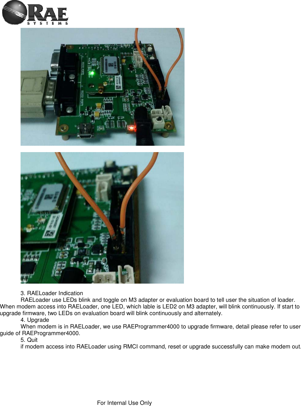
![RAEMesh2 User Manual Doc.No: Originator: kren Page 6 of 38Data: 2014-3-18 4. Firmware The module is pre-loaded with the bootloader, which supports serial bootloading of firmware update. The module contains RAEMesh application and comply with the RAE System’s RCS protocol. The module also hasbuilt-in RAEMesh Module Command Interface(RMCI). This documentation is focused on the instruction on RMCI interface. The RMCI command interface allows customer to easily access to low level mesh functionality without pain to develop the firmware. The module can be configured to a GTW to hook up to a getaway or just a stand alone regular full function node or a Sleepy reduce function node. Make sure to configure the module to right mode before using. 1) Quick Start UART Via the TXD1 and RXD1 pins the command interpreter can be accessed. The RCM can buffer up to 128 bytes of incoming data in a software FIFO buffer and uses XON/XOFF flow control. See the datasheet of the Atmel ATmega1281 for more information about the build-in UART. Connect Pin5 (TXD1) and Pin7 (RXD1) to the customer board. Use the following settings for serial port.RTR and STD: 19200bps, 8N1. GTW: 38400bps, 8N1. Data Packet RCM will transmit any data in the { }, all data in the {} will be transparently sent out without radio’s interpretation. The maximum data packet is 90 bytes including {}.The data in the {} can be any characters including ‘{‘ ‘}’ ’[‘ ’]’ . The interval between 2 data packets must be >200ms for RTR and GTW.The interval between 2 data packets must be >1s for STD. Wakeup If the radio is set to STD mode, the Wakeup pin Pin19 (PE7) is used to make the radio asleep and wakeup. A constant high on this pin will let the radio go to the sleep mode and a low level signal on this pin will wake-up the radio. The Radio sleep mode is the power save mode so the power consumption can be very low. (<40uA) The Wakeup pin must be held up to 10ms before sending a data packet. Power Ground: Pin1, Pin2 and Pin4. VCC: Pin39, Pin40. 3.0V or 3.3V Radio consumes less than 100mW in normal RX/TX mode. Radio consumes 600mW at TX and 100mW at RX for High power module Heartbeat Connect Pin12 to a LED for heartbeat indicator.](https://usermanual.wiki/RAE-Systems/RM900/User-Guide-2293072-Page-6.png)
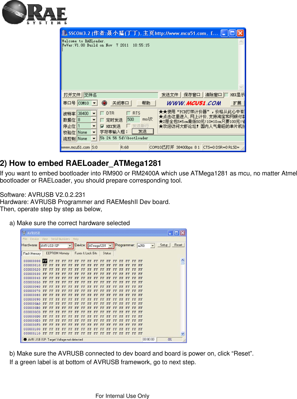
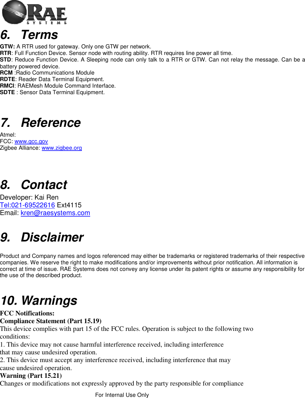
![RAEMesh2 User Manual Doc.No: Originator: kren Page 7 of 38Data: 2014-3-18 Reset. RST: Pin3 Active Low. PC communication Please has your serial port debug software installed on the PC. For example: sscom32.exe Microsoft Hyper Terminal is not recommended for this application because it is not good to send characters and commands in Hex. Base on correct setting and connection, you will see following display on your screen when power is applied. GTW: Ă[%A ]RAEMESH-II RM2400A 8MHz FwVer:V1.02b on Sep 28 2011 09:52:14 Stack: BC1.10.0 Type: Coordinator/Gateway Band: 2400 EUI: 0001002400001005 Channel: 0x10 TxPwr: Medium PanId: 0x03E5 RTR: ١[%A ]RAEMESH-II RM2400A 8MHz FwVer:V1.02b on Sep 28 2011 09:52:14 Stack: BC1.10.0 Type: FFD/Router Band: 2400 EUI: 0001002400001005 Channel: 0x10 TxPwr: Medium PanId: 0x03E5 STD ١[%A ]RAEMESH-II RM2400A 8MHz FwVer:V1.02b on Sep 28 2011 09:52:14 Stack: BC1.10.0 Type: RFD Sleep Sensor Band: 2400 EUI: 0001002400001005 Channel: 0x10 TxPwr: Medium PanId: 0x03E5](https://usermanual.wiki/RAE-Systems/RM900/User-Guide-2293072-Page-7.png)
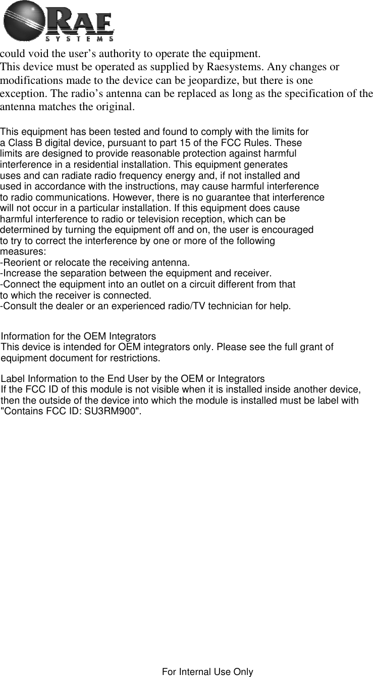
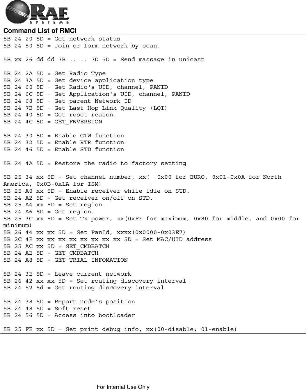
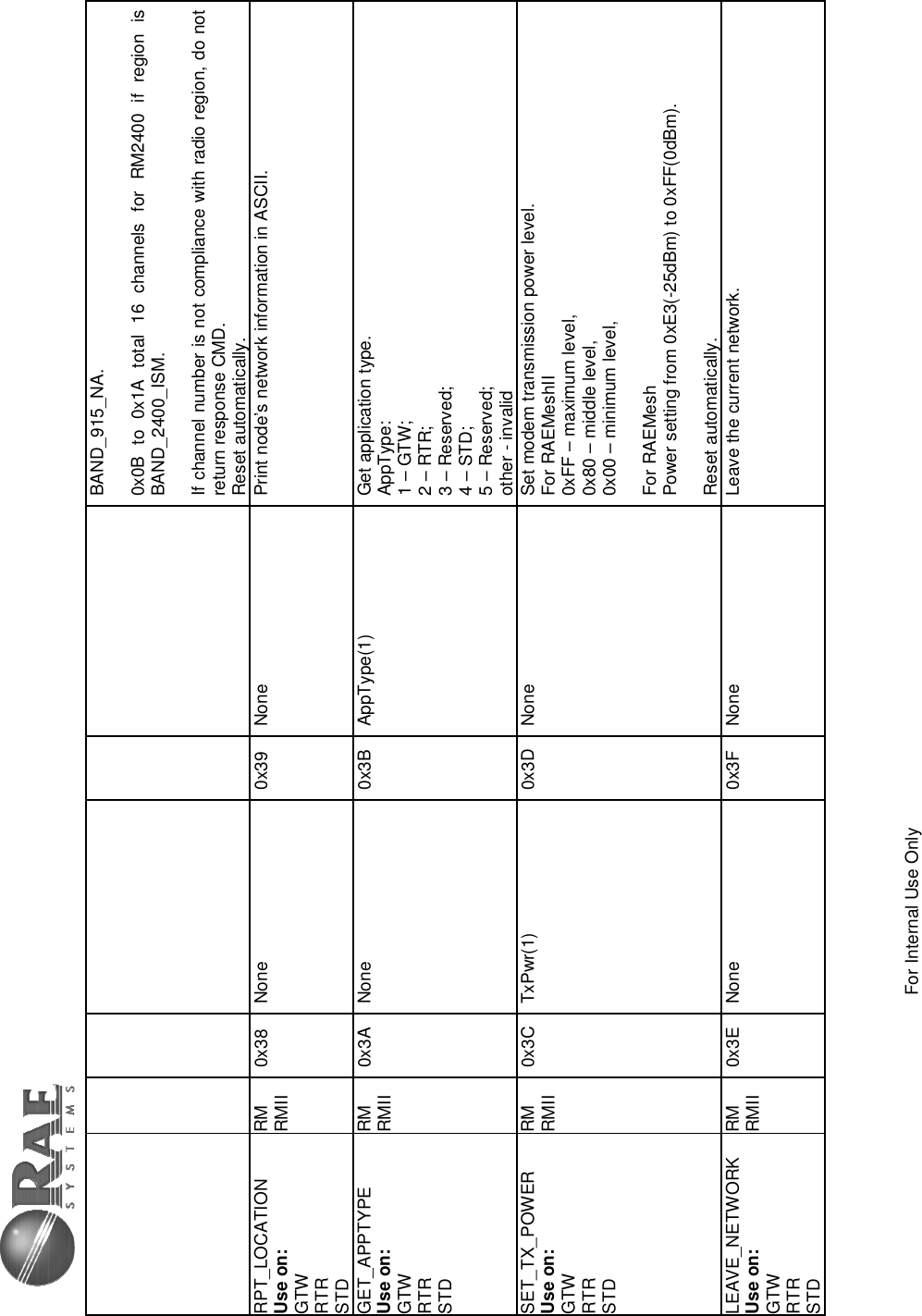
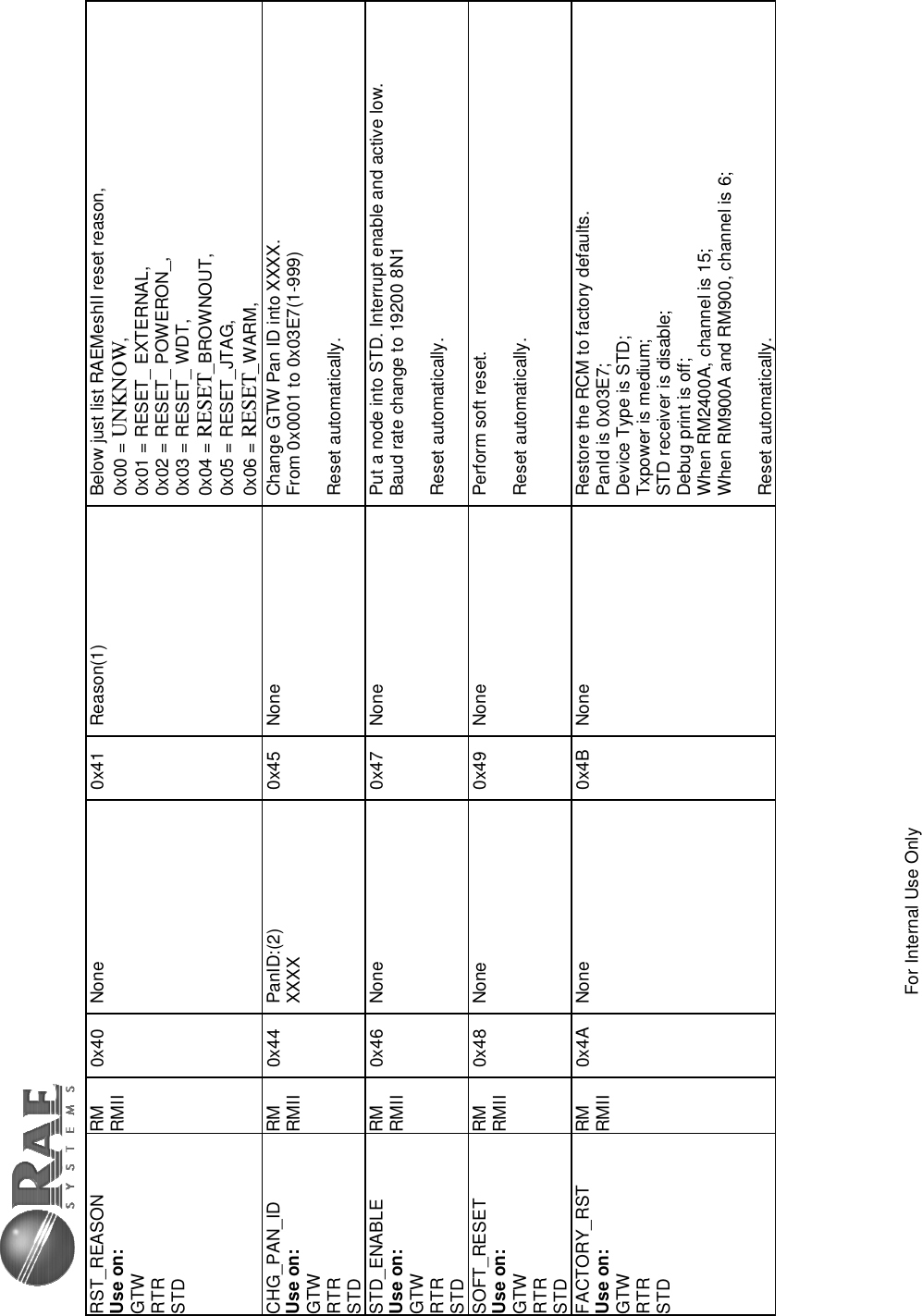
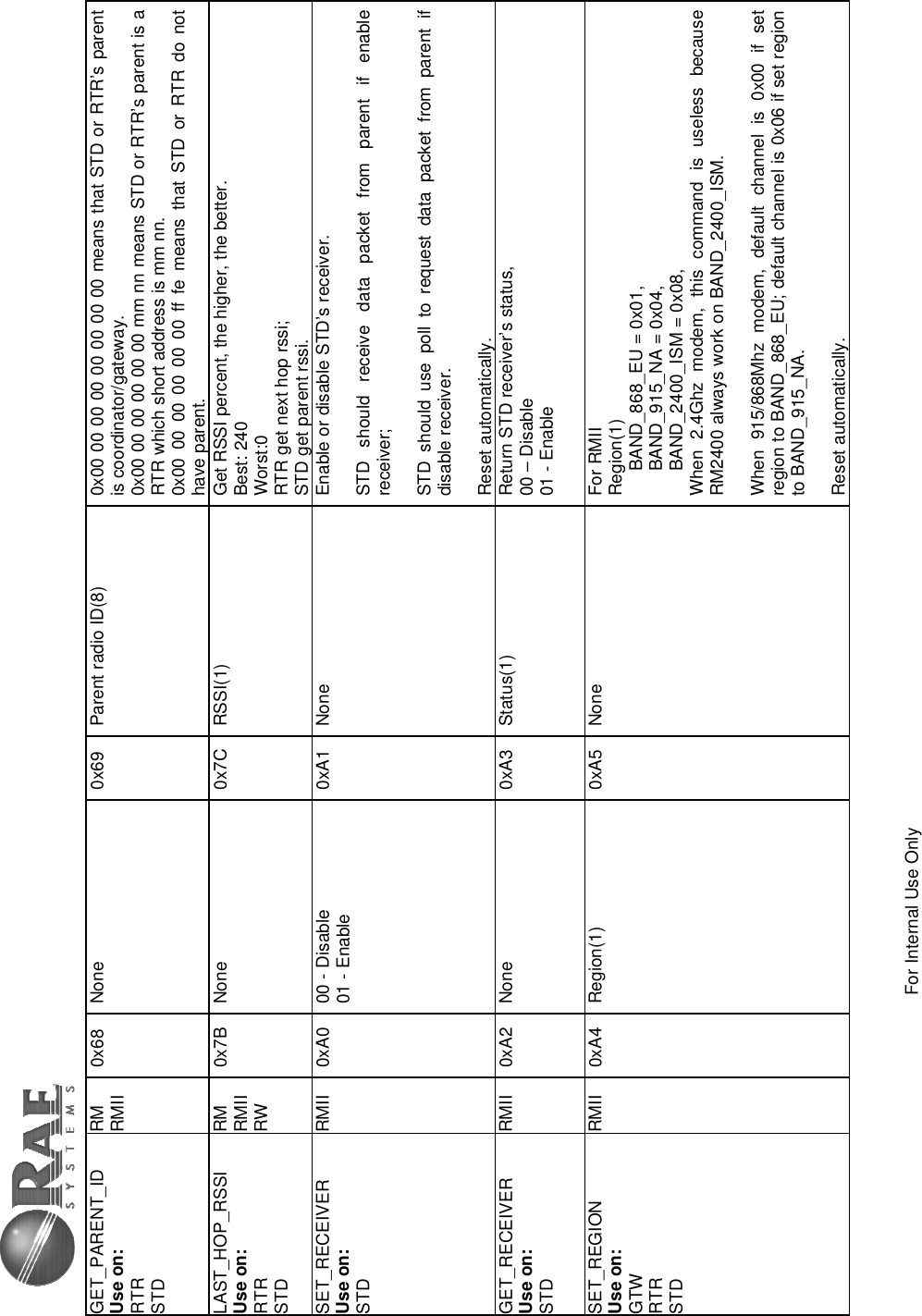
![RAEMesh2 User Manual Doc.No: Originator: kren Page 8 of 38Data: 2014-3-18 2) RAEMesh Module Command Interface Format: SOP Length Command Code Command Data EOP Byte: 1 1 1 0~n 1 Byte Number Name Comment 0 SOP Radio Protocol beginning of packet. This is always ‘[‘ (0x5B) 1 Length Total length of packet + 0x20, include ‘[‘ and ‘]’. 2 Command Code 0x20 ~ 0xFF. Excluding:0x5A~0x5F and 0x7A~0x7F. 0xF0~0xFF are reserved for common commands. Even for packet sent from SDTE or RDTE to RCM. Odd for packet response from RCM to SDTE or RDTE. 3 Command Data Hex … … N+3 EOP Radio protocol end of packet.. This is always ‘]’(0x5D) The minimum length for one packet is 4 bytes long. The Length is 0x20 based. E.g. the total length of a packet without command data is 4, the Length byte is 0x20 + 4 = 0x24. The SDTE or RDTE always initiate the communication with Radio module (RRCM, SRCM). Radio Module responses to the command it received. The Command Code for packet sent from SDTE or RDTE to Radio module is even, the response from Radio module to SDTE or RDTE is 1 higher than the command code. Command Data can be empty. No command for 0x5A~0x5F and 0x7A~0x7F. A Section 0xF0~0xFF is reserved for common commands such as help, Version etc. Caution: the maximum packet length from SOP to EOP is 64 bytes. Notes:1. All commands response in 50ms2. Check RCM’s information when turn on the radio. Command: 5B 24 60 5D. 3. Wait at least 5s for RCM to finish the initialization after power on. 4. Check the network status of the STD before sending the data for first time. Command: 5B 24 20 5D. 5. It is recommend to add 1s interval between 2 data packets for STD. Check 0x5b 24 27 5d for sending acknowledge with successfully. There is no ACK for transmission failed. 6. For STD, if there is no network, the RCM will automatically wake up every 10 minute to search for a new network. It can be interrupted any time. RCM will keep in asleep if it has joined a network.](https://usermanual.wiki/RAE-Systems/RM900/User-Guide-2293072-Page-8.png)
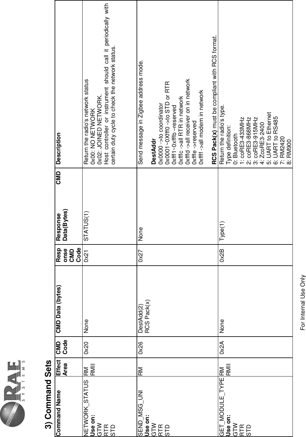
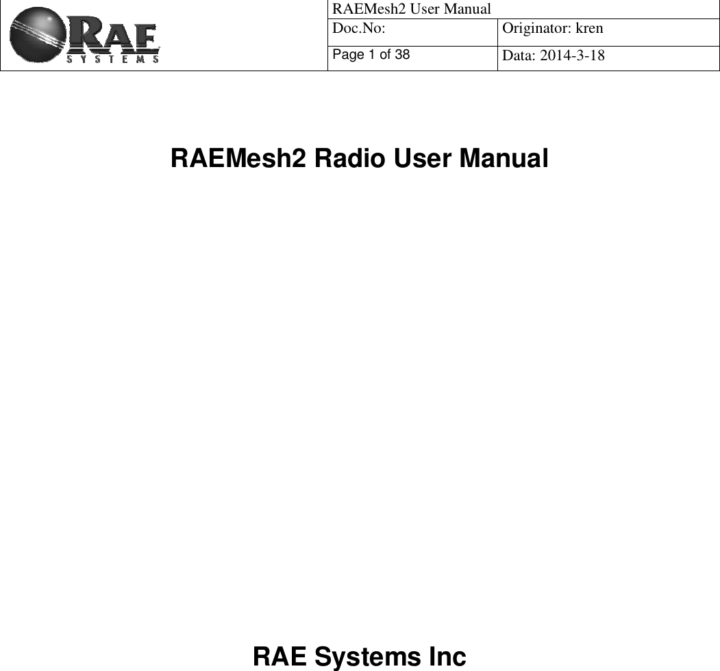
![For Internal Use Only GET_FWVERSION Use on: GTW RTR STD RM RMII RW 0x4C None 0x4D Fw Version and Build Time[30] Return fw version and build time, for example [BMv1.00 Feb 14 2011 10:11:11], this mean fw version is V1.00 and build is on Feb 14 2011 10:11:11. SET_UID Use on: GTW RTR STD RMII 0x4E UID(8) 0x4F None For RMII: Set radio’s UID(MAC address). Note: The last two bytes must not set to 0x0000, 0xFFF0-0xFFFF Reset automatically. JION_FORM_NETWORK Use on: GTW RTR STDRM RMII 0x50 None 0x51 None GTW: Form a network using customized PANID to allow the other nodes to join. RTR/STD: Search the network using customized PANID and try to join the network. GET_NEIGHBOUR_LIST Use on: GTW RTR STD RMII 0x54 None 0x55 Node[0] shortAddr[2] rssi[1] relation[1] depth[1] Node[1]… Node[2]… … Neighbor table list like this: shortAddr: Short address when network is up. RSSI: Best: 240, Worst:0 Relation: PARENT = 0x00 CHILD = 0x01 SIBLING = 0x02 NONE_OF_ABOVE = 0x03 PREVIOUS_CHILD = 0x04 UNAUTHENTICATED_CHILD = 0x05 EMPTY = 0x06 Depth: Network depth in the routing link toward coordinator.](https://usermanual.wiki/RAE-Systems/RM900/User-Guide-2293072-Page-15.png)
![For Internal Use Only SET_BOOTLOADER Use on: GTW RTR STD RM RMII 0x56 None 0x57 None Make modem into bootloader mode and wait for new app image. SYS_CTRL_SET RMII 0x58 System Control Word, B[3]…B[0] 0x59 00 – failed 01 – success System Control Word. Bit0: Roaming function, 1 – enable; 0 – disable; Bit1: pending, AES128 security, 1 – enable; 0 – disable; Bit2: Receiver setting of RFD; 1 – always on when idle; 0 – power saving mode; . . . Bit31: reversed;SYS_CTRL_GET RMII 0x5A None 0x5B System Control Word, B[3]…B[0] Get System Control Word. SEC_KEY_SET RMII 0x5C KEY[15]…KEY[0] 0x5D 00- failed 01- success Set AES-128 key for application encrypt/decrypt. GET_NODE_INFO Use on: GTW RTR STD RM RMII 0x60 None 0x61 UID(8) Channel(1) Power(1) PAN ID(2) Get the node information: UID, Channel, Txpower level,, PAN ID, GET_APPNODE_INFO Use on: GTW RTR STD RM RMII 0x6C None 0x6D UID(8) Channel(1) Power(1) PAN ID(2) Get the application information: UID, Channel, Power, PAN ID. If the network is not connected, the GET_NODE_INFO will return wrong information, and then use this to get what we set.](https://usermanual.wiki/RAE-Systems/RM900/User-Guide-2293072-Page-16.png)
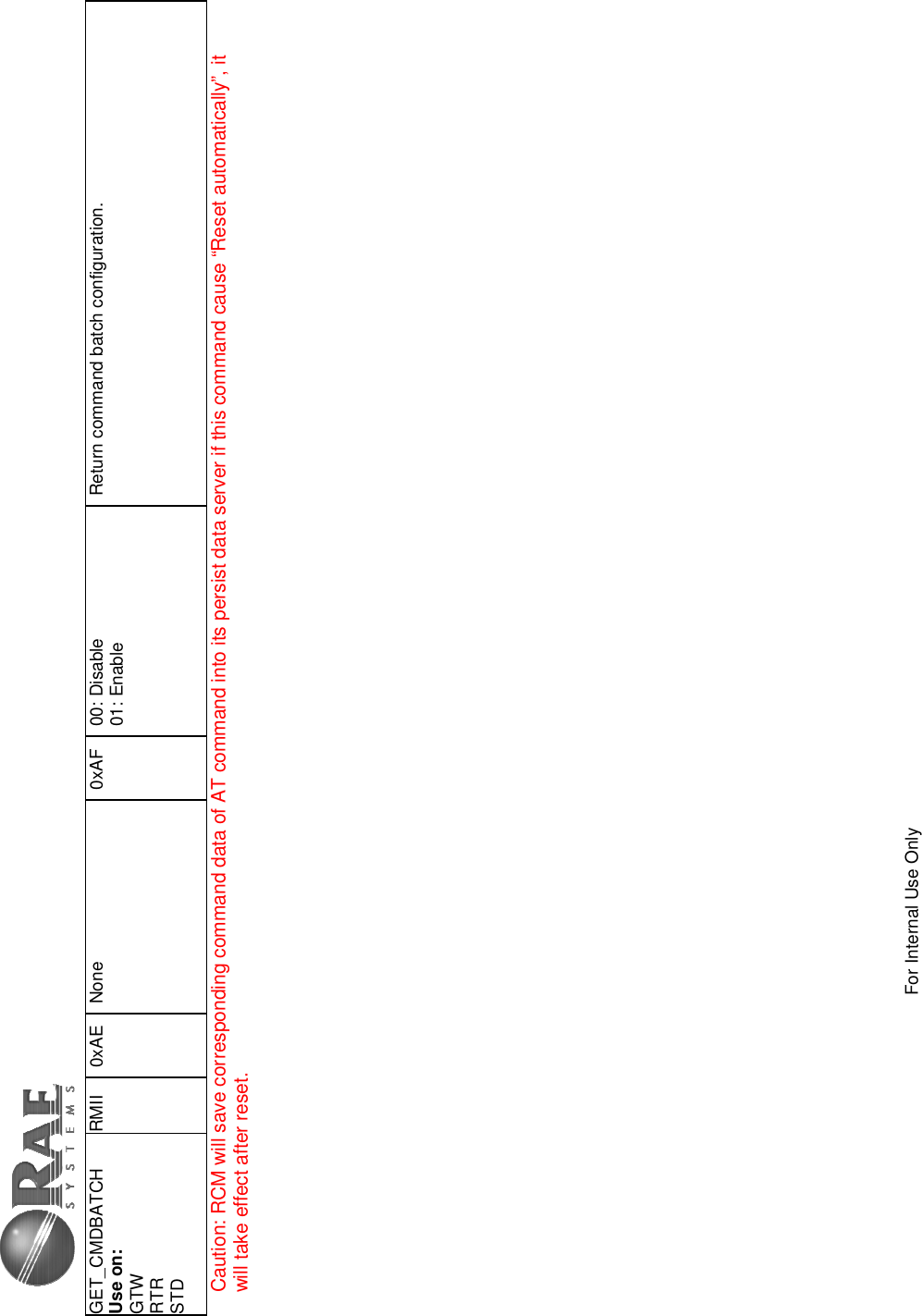
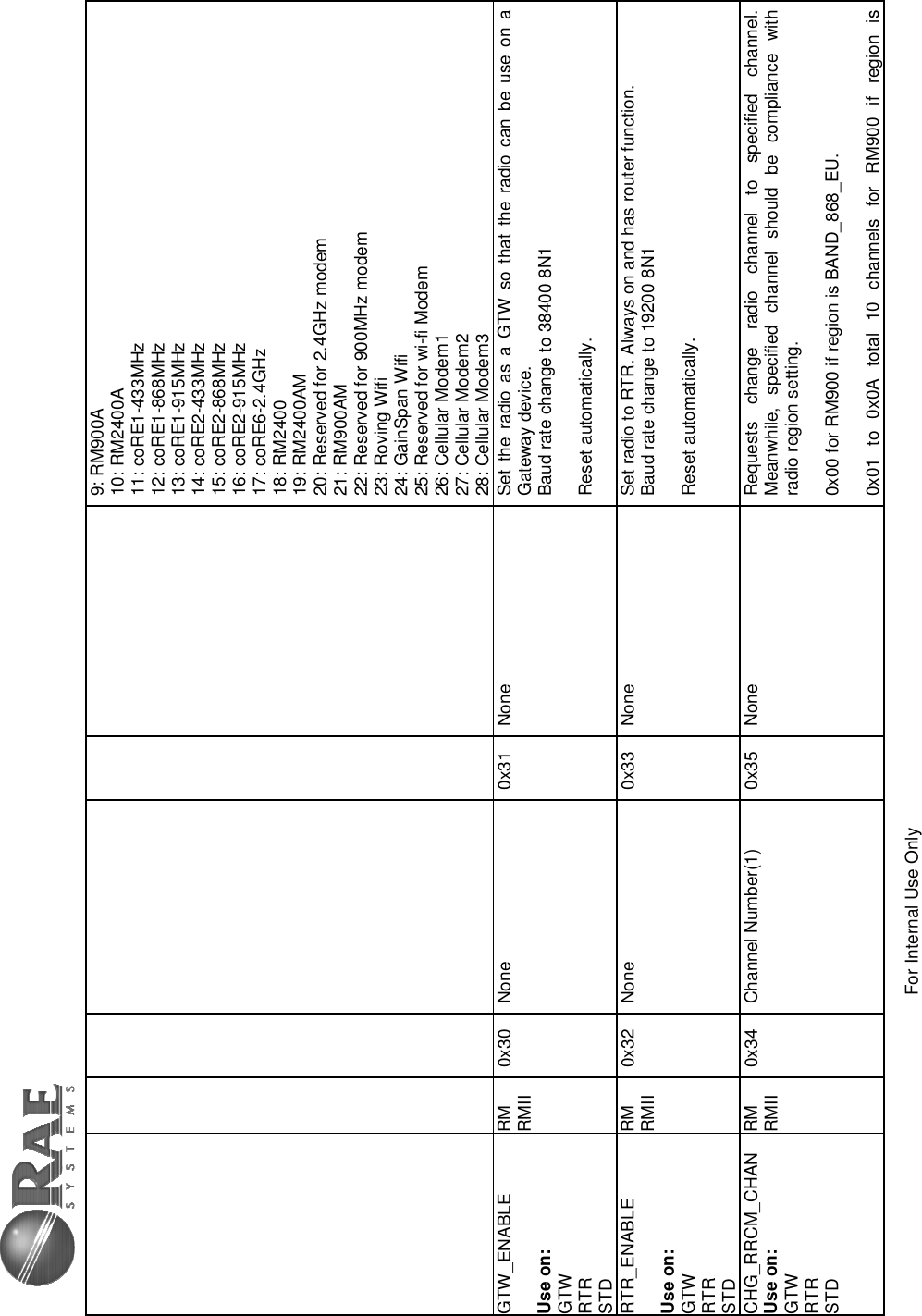
![For Internal Use Only GET_REGION Use on: GTW RTR STD RMII RW 0xA6 None 0xA7 Region(1) Get modem setting of region. GET_TRAIL_INFO Use on: GTW RTR STD RMII 0xA8 None 0xA9 NWK_INFO[16] Use this command to get modem trail information. BYTE0: modem reset count. This count should be increased if any reset occur.(0~255) BYTE1: reset reason. 0x00 = UNKNOW, 0x01 = EXTERNAL, 0x02 = POWERON 0x03 = WATCHDOG, 0x04 = BROWNOUT, 0x05 = JTAG, 0x06 = WARM BYTE2: network depth(0~15) BYTE3~BYTE15: reserved.SET_DEBUG_PRINT Use on: GTW RTR STD RM RMII 0xFE 00,Disable 01,Enable 0xFF None Set display debug information enable/disable. The default setting is disabled. SET_CMDBATCH Use on: GTW RTR STD RMII 0xAC 00, Disable 01, Enable 0xAD None Enable or disable command batch function. If enable, modem will not reset automatically after change panid, channel, power, eui, regionˈ receiver and join permission. They will take effect after reset manually. Batch function will disable after reset.](https://usermanual.wiki/RAE-Systems/RM900/User-Guide-2293072-Page-18.png)