RAE Systems RM900 RAEmesh Radio (RM900) User Manual SU3RM900
RAE Systems, Inc RAEmesh Radio (RM900) SU3RM900
User Manual

RAEMesh2 User Manual
Doc.No: Originator: kren
Page 1 of 38
Data: 2014-3-18
RAEMesh2 Radio User Manual
RAE Systems Inc
RAEMesh2 User Manual
Doc.No: Originator: kren
Page 2 of 38
Data: 2014-3-18
Revision
Date
Comments
Author
0.1
11/28/2008
Initial
Alven
0.2
12/1/2008
Add “Radio Core Setting Procedure”
Alven
0.3
1/4/2009
Add “Fuse config”, “Firmware programmer”
Alven
0.
4
1/5/2009
Add “Soft Reset” command
Alven
0.5
3/26/2010
Add
“
Reset reason
”
command
kren
0.6
4/22
/2010
Add description about TXPOWER and
Channel setting
kren
0.7
5/20/10
Add START_ROUTING command.
Change
SET_FACTORY_RST
for RM2400
kren
0.8
5/25/10
Ad
d RAEMesh and RAEMesh
-
II difference,
CHG START_ROUTING to
SET_ROUTEINTERVAL, add
GET_ROUTEINTERVAL and SET_REGION.
kren
0.9
8//17/10
Modify ModuleType
definition
.
kren
1.0
10/14/10
A
dd modem longest startup time;
Add modem longest packet length from SOP
to EOP; rename “RFD” as “STD”,
rename “FFD” as “RTR”, rename
“Coordinator” as “GTW”.
kren
1.1
11/19/10
E
rror, best rssi of at command response is
240, not 100.
kren
1.2
01/31/11
Add new command,
GET_FWVERSION
kren
1.3
03/25/11
A
dd new commands,
SE
T_CMDBATCH
and
GET_CMDBATCH
kren
1.4
04/07/11
M
odify
GET_PARENT_ID
definition.
Modem return 0x5b 24 27 5d when it transmit
a pack and get acknowledge successfully.
kren
1.5
6/28/2011
A
dd
SET_BOOTLOADER
kren
11/25/2011
A
dd bootloader section
kren
5/8
/2012
A
dd RM900A module type.
Add SAM7X RAELoader Section
Add RM900A low temperature current
comsumption.
kren
5/23/2012
A
dd RM2400, RM2400AM, RM900AM, Wifi and
Cellular modem type.
kren
8/16/
2013
M
odify FACTORY_RESET.
kren
9/23/13
A
dd GET_TRIAL_INFO
kren
1/23/14
Add Wi
-
Fi related command
Wu Wei
2/18/14
Add three
commands, SYS_CTRL
_GET,
SYS_CTRL_SET, SEC_KEY_SET
kren
04/03/14
Delete Wi
-
Fi related command
Wu Wei
4/3/2014
Add
GET
_NEIGHBOUR_LIST
kren
RAEMesh2 User Manual
Doc.No: Originator: kren
Page 3 of 38
Data: 2014-3-18
1. Introduction
The RAEMesh Radio module offers a complete microcontroller/transceiver solution Containing all hardware features
necessary for development of a low data-rate, low-power wireless application. The primary components include an IEEE
802.15.4 compliant Zigbee-ready transceiver , a microcontroller, a 40-pin interface connector, a MMCS antenna
connector,
This documentation describes the RAEMesh radio module hardware interface as well as RAE System’s Command
Interface.
2. Hardware
1) Specifications
Frequency Band
802.15.4 standard.
2.4Ghz:16 channels of operation in the 2.4GHz world wide ISM band. 5MHz
channel spacing.
915Mhz: 10 channels. 906,908……924Mhz
868Mhz: 1 channel, 868Mhz
Power
+3.3V + .3V from carrier board, 3.0V to 3.6V from battery pack
Interfaces
40-pin surface-mount 2x20 1.27mm pitch
RF 250kbps OQPSK Direct Sequence Spread Spectrum @2.4GHz
40kbps BPSK DSSS @915MHz
20kbps BPSK DSSS @868MHz
Dimensions
46.5 mm x 26 mm x 10 mm
Antenna Interface
50-Ohm MMCX female
Operating Temperature Range -40ºC to +85ºC
Indicators
Two LEDs, one red, one yellow (DS1, DS2)
Current Consumption
RM2400A 23µA Sleep
120 mA TX @Medium Level 18dBm
25 mA RX / Idle
RM900 23µA Sleep
50 mA TX @High Level 11dBm
20mA RX / Idle
RM900A 600µA Sleep
170mA TX 25ć or 200mA TX -20ć@Medium Level
35mA RX/Idel
RF receive sensitivity
-100dBm at at 1% packet error rate for a 20 byte payload.
RAEMesh2 User Manual
Doc.No: Originator: kren
Page 4 of 38
Data: 2014-3-18
2) Pin Layout
Pin
Description
Pin
Description
1 DGND 2 DGND
3 nRESET 4 DGND
5 TXD1 6 TXD0/Bootload.
7 RXD1 8 RXD0
9 GPIO0 10 GPIO/LED2
11 GPIO1 12 GPIO/LED3
13 GPIO2 14 GPIO/LED4
15 GPIO3 16 GPIO/LED5
17 TEMP_E/GPIO4 18 GPIO/PS_CS
19 WakeUp/GPIO5 20 GPIO/PS_FRAME
21 BUZZER/GPIO6 22 +3.3V
23 GPIO7/PS_DIR 24 AGND
25 BUTTON0/GPIO8 26 AREF
27 BUTTON1/GPIO9 28 ATEMP/ADC1
29 GPIO10 30 ADC2
31 RF_SO 32 TCK
33 RF_SI 34 TMS
35 RF_CK 36 TDO
37 SFD 38 TDI
39 +3.3V 40 +3.3V
RAEMesh2 User Manual
Doc.No: Originator: kren
Page 5 of 38
Data: 2014-3-18
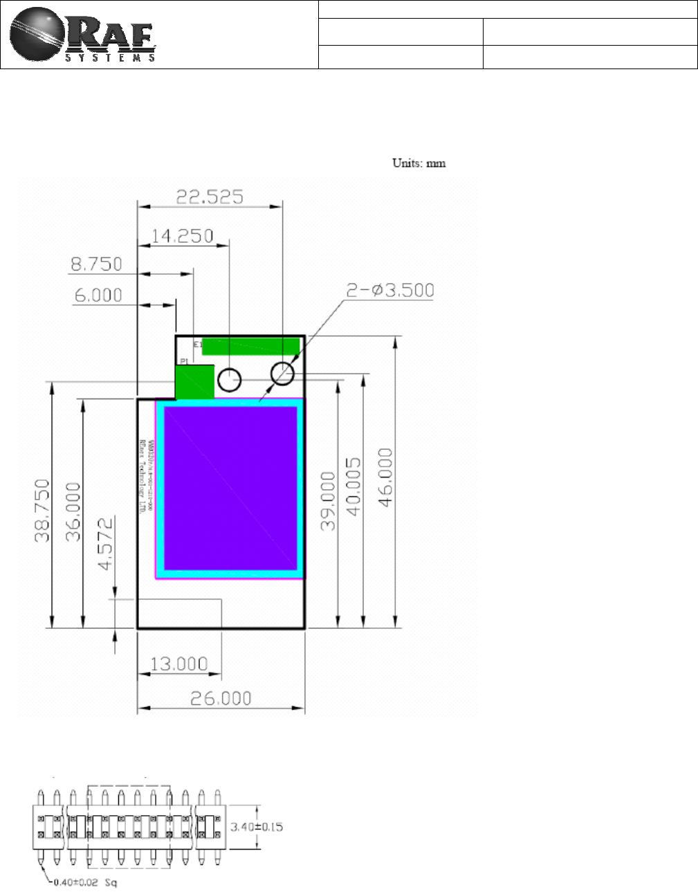
3. Mechanical Size
Top View
The height of the shielding box is 4.3mm from the PCB.
40 Pin header (1.27mm) is used for board to board connection. Corresponding mate connector can be JVE
22P8702-40M00B-01G-4.5
RAEMesh2 User Manual
Doc.No: Originator: kren
Page 6 of 38
Data: 2014-3-18
4. Firmware
The module is pre-loaded with the bootloader, which supports serial bootloading of firmware update. The
module contains RAEMesh application and comply with the RAE System’s RCS protocol. The module also has
built-in RAEMesh Module Command Interface(RMCI).
This documentation is focused on the instruction on RMCI interface.
The RMCI command interface allows customer to easily access to low level mesh functionality without pain to
develop the firmware. The module can be configured to a GTW to hook up to a getaway or just a stand alone
regular full function node or a Sleepy reduce function node.
Make sure to configure the module to right mode before using.
1) Quick Start
UART
Via the TXD1 and RXD1 pins the command interpreter can be accessed. The RCM can buffer up to 128 bytes of incoming
data in a software FIFO buffer and uses XON/XOFF flow control. See the datasheet of the Atmel ATmega1281 for more
information about the build-in UART.
Connect Pin5 (TXD1) and Pin7 (RXD1) to the customer board. Use the following settings for serial port.
RTR and STD: 19200bps, 8N1.
GTW: 38400bps, 8N1.
Data Packet
RCM will transmit any data in the { }, all data in the {} will be transparently sent out without radio’s interpretation. The
maximum data packet is 90 bytes including {}.
The data in the {} can be any characters including ‘{‘ ‘}’ ’[‘ ’]’ .
The interval between 2 data packets must be >200ms for RTR and GTW.
The interval between 2 data packets must be >1s for STD.
Wakeup
If the radio is set to STD mode, the Wakeup pin Pin19 (PE7) is used to make the radio asleep and wakeup. A constant
high on this pin will let the radio go to the sleep mode and a low level signal on this pin will wake-up the radio.
The Radio sleep mode is the power save mode so the power consumption can be very low. (<40uA)
The Wakeup pin must be held up to 10ms before sending a data packet.
Power
Ground: Pin1, Pin2 and Pin4.
VCC: Pin39, Pin40. 3.0V or 3.3V
Radio consumes less than 100mW in normal RX/TX mode.
Radio consumes 600mW at TX and 100mW at RX for High power module
Heartbeat
Connect Pin12 to a LED for heartbeat indicator.

RAEMesh2 User Manual
Doc.No: Originator: kren
Page 7 of 38
Data: 2014-3-18
Reset.
RST: Pin3 Active Low.
PC communication
Please has your serial port debug software installed on the PC. For example: sscom32.exe
Microsoft Hyper Terminal is not recommended for this application because it is not good to send characters and
commands in Hex.
Base on correct setting and connection, you will see following display on your screen when power is applied.
GTW:
Ă
[%A ]RAEMESH-II RM2400A 8MHz
FwVer:V1.02b on Sep 28 2011 09:52:14
Stack: BC1.10.0
Type: Coordinator/Gateway
Band: 2400
EUI: 0001002400001005
Channel: 0x10
TxPwr: Medium
PanId: 0x03E5
RTR:
١
[%A ]RAEMESH-II RM2400A 8MHz
FwVer:V1.02b on Sep 28 2011 09:52:14
Stack: BC1.10.0
Type: FFD/Router
Band: 2400
EUI: 0001002400001005
Channel: 0x10
TxPwr: Medium
PanId: 0x03E5
STD
١
[%A ]RAEMESH-II RM2400A 8MHz
FwVer:V1.02b on Sep 28 2011 09:52:14
Stack: BC1.10.0
Type: RFD Sleep Sensor
Band: 2400
EUI: 0001002400001005
Channel: 0x10
TxPwr: Medium
PanId: 0x03E5
RAEMesh2 User Manual
Doc.No: Originator: kren
Page 8 of 38
Data: 2014-3-18
2) RAEMesh Module Command Interface
Format:
SOP Length Command Code Command Data EOP
Byte: 1 1 1 0~n 1
Byte Number Name Comment
0 SOP Radio Protocol beginning of packet. This is always ‘[‘ (0x5B)
1 Length Total length of packet + 0x20, include ‘[‘ and ‘]’.
2 Command Code 0x20 ~ 0xFF. Excluding:0x5A~0x5F and 0x7A~0x7F. 0xF0~0xFF are
reserved for common commands.
Even for packet sent from SDTE or RDTE to RCM.
Odd for packet response from RCM to SDTE or RDTE.
3 Command Data Hex
… …
N+3 EOP Radio protocol end of packet.. This is always ‘]’(0x5D)
The minimum length for one packet is 4 bytes long. The Length is 0x20 based. E.g. the total length of a packet without
command data is 4, the Length byte is 0x20 + 4 = 0x24.
The SDTE or RDTE always initiate the communication with Radio module (RRCM, SRCM). Radio Module responses to
the command it received.
The Command Code for packet sent from SDTE or RDTE to Radio module is even, the response from Radio module to
SDTE or RDTE is 1 higher than the command code.
Command Data can be empty.
No command for 0x5A~0x5F and 0x7A~0x7F.
A Section 0xF0~0xFF is reserved for common commands such as help, Version etc.
Caution: the maximum packet length from SOP to EOP is 64 bytes.
Notes:
1. All commands response in 50ms
2. Check RCM’s information when turn on the radio. Command: 5B 24 60 5D.
3. Wait at least 5s for RCM to finish the initialization after power on.
4. Check the network status of the STD before sending the data for first time. Command: 5B 24 20 5D.
5. It is recommend to add 1s interval between 2 data packets for STD. Check 0x5b 24 27 5d for sending
acknowledge with successfully. There is no ACK for transmission failed.
6. For STD, if there is no network, the RCM will automatically wake up every 10 minute to search for a new network.
It can be interrupted any time. RCM will keep in asleep if it has joined a network.

For Internal Use Only
Table1 RAEMesh and RAEMeshII Difference
Item
RAEMesh
RAEMeshII
Description
Hardware MCU: ATMEGA128L
Radio: EM2420 MCU: ATMEGA1281V
Radio: AT86RF212,
AT86RF230, AT86RF231
N/A
Stack Ember Zigbee Stack Atmel Bitcloud N/A
Specification Zigbee 2004 Zigbee Pro Owing to the difference of specification, RAEMesh
and RAEMeshII can’t inter-communication
Power Failure Support Un-support In RAEMesh, all device can save their child or
neighbor table into eeprom.
RAEMeshII can’t support this feature, so they
should re-form or re-join by themselves after
reset.
RSSI Router/RTR update
RSSI when it receive
every frame.
Router/RTR read next
hop’s RSSI. Next hop is that Router/RTR send frame to GTW
through next hop’s routing.
Many-to-one
routing(MTOR) Support Un-support In RAEMesh, GTW manage MTOR periodically
and automatically.
In RAEMeshII, Router need to do route discovery
and maintenance by themselves.
EUI Set it on RangeTest. Set it on application
firmware. N/A
Transmission
power Always is maximum. There are three level to be
choose. In RAEMeshII, high, medium and low represent
different txpower on different platform.
Bootloader Provide by Ember Provide by Atmel N/A
Warm up time time scale of
milliseconds More than five seconds N/A

For Internal Use Only
Command List of RMCI
5B 24 20 5D = Get network status
5B 24 50 5D = Join or form network by scan.
5B xx 26 dd dd 7B .. .. 7D 5D = Send massage in unicast
5B 24 2A 5D = Get Radio Type
5B 24 3A 5D = Get device application type
5B 24 60 5D = Get Radio's UID, channel, PANID
5B 24 6C 5D = Get Application's UID, channel, PANID
5B 24 68 5D = Get parent Network ID
5B 24 7B 5D = Get Last Hop Link Quality (LQI)
5B 24 40 5D = Get reset reason.
5B 24 4C 5D = GET_FWVERSION
5B 24 30 5D = Enable GTW function
5B 24 32 5D = Enable RTR function
5B 24 46 5D = Enable STD function
5B 24 4A 5D = Restore the radio to factory setting
5B 25 34 xx 5D = Set channel number, xx( 0x00 for EURO, 0x01-0x0A for North
America, 0x0B-0x1A for ISM)
5B 25 A0 xx 5D = Enable receiver while idle on STD.
5B 24 A2 5D = Get receiver on/off on STD.
5B 25 A4 xx 5D = Set region.
5B 24 A6 5D = Get region.
5B 25 3C xx 5D = Set Tx power, xx(0xFF for maximum, 0x80 for middle, and 0x00 for
minimum)
5B 26 44 xx xx 5D = Set PanId, xxxx(0x0000-0x03E7)
5B 2C 4E xx xx xx xx xx xx xx xx 5D = Set MAC/UID address
5B 25 AC xx 5D = SET_CMDBATCH
5B 24 AE 5D = GET_CMDBATCH
5B 24 A8 5D = GET TRIAL INFOMATION
5B 24 3E 5D = Leave current network
5B 26 42 xx xx 5D = Set routing discovery interval
5B 24 52 5d = Get routing discovery interval
5B 24 38 5D = Report node’s position
5B 24 48 5D = Soft reset
5B 24 56 5D = Access into bootloader
5B 25 FE xx 5D = Set print debug info, xx(00-disable; 01-enable)

For Internal Use Only
3) Command Sets
Command Name
Effect
Area
CMD
Code
CMD Data
(bytes)
Resp
onse
CMD
Code
Response CMD
Data(Bytes)
Description
NETWORK_STATUS
Use on:
GTW
RTR
STD
RM
RMII 0x20 None 0x21 STATUS(1) Return the radio’s network status
0x00: NO NETWORK
0x02: JOINED NETWORK.
Host controller or instrument should call it periodically with
certain duty cycle to check the network status.
SEND_MSG_UNI
Use on:
GTW
RTR
STD
RM 0x26 DestAdd(2)
RCS Pack(x) 0x27 None Send message in Zigbee address mode.
DestAddr
0x0000 ->to coordinator
0x0001~0Xfff0 ->to STD or RTR
0xfff1~0xfffb –reserved
0xfffc ->all RTR in network
0xfffd ->all receiver on in network
0xfffe ->reserved
0xffff ->all modem in network
RCS Pack(x) must be compliant with RCS format.
GET_MODULE_TYPE
Use on:
GTW
RTR
STD
RM
RMII 0x2A None 0x2B Type(1) Return the radio’s type.
Type definition:
0: Bluetooth
1: coRE3-433MHz
2: coRE3-868MHz
3: coRE3-915MHz
4: ZcoRE3-2400
5: UART to Ethernet
6: UART to RS485
7: RM2420
8: RM900

For Internal Use Only
9: RM900A
10: RM2400A
11: coRE1-433MHz
12: coRE1-868MHz
13: coRE1-915MHz
14: coRE2-433MHz
15: coRE2-868MHz
16: coRE2-915MHz
17: coRE6-2.4GHz
18: RM2400
19: RM2400AM
20: Reserved for 2.4GHz modem
21: RM900AM
22: Reserved for 900MHz modem
23: Roving Wifi
24: GainSpan Wifi
25: Reserved for wi-fi Modem
26: Cellular Modem1
27: Cellular Modem2
28: Cellular Modem3
GTW_ENABLE
Use on:
GTW
RTR
STD
RM
RMII 0x30 None 0x31 None Set the radio as a GTW so that the radio can be use on a
Gateway device.
Baud rate change to 38400 8N1
Reset automatically.
RTR_ENABLE
Use on:
GTW
RTR
STD
RM
RMII 0x32 None 0x33 None Set radio to RTR. Always on and has router function.
Baud rate change to 19200 8N1
Reset automatically.
CHG_RRCM_CHAN
Use on:
GTW
RTR
STD
RM
RMII 0x34 Channel Number(1) 0x35 None Requests change radio channel to specified channel.
Meanwhile, specified channel should be compliance with
radio region setting.
0x00 for RM900 if region is BAND_868_EU.
0x01 to 0x0A total 10 channels for RM900 if region is

For Internal Use Only
BAND_915_NA.
0x0B to 0x1A total 16 channels for RM2400 if region is
BAND_2400_ISM.
If channel number is not compliance with radio region, do not
return response CMD.
Reset automatically.
RPT_LOCATION
Use on:
GTW
RTR
STD
RM
RMII 0x38 None 0x39 None Print node’s network information in ASCII.
GET_APPTYPE
Use on:
GTW
RTR
STD
RM
RMII 0x3A None 0x3B AppType(1) Get application type.
AppType:
1 – GTW;
2 – RTR;
3 – Reserved;
4 – STD;
5 – Reserved;
other - invalid
SET_TX_POWER
Use on:
GTW
RTR
STD
RM
RMII 0x3C TxPwr(1) 0x3D None Set modem transmission power level.
For RAEMeshII
0xFF – maximum level,
0x80 – middle level,
0x00 – minimum level,
For RAEMesh
Power setting from 0xE3(-25dBm) to 0xFF(0dBm).
Reset automatically.
LEAVE_NETWORK
Use on:
GTW
RTR
STD
RM
RMII 0x3E None 0x3F None Leave the current network.

For Internal Use Only
RST_REASON
Use on:
GTW
RTR
STD
RM
RMII 0x40 None 0x41 Reason(1) Below just list RAEMeshII reset reason,
0x00 =
UNKNOW
,
0x01 = RESET_ EXTERNAL,
0x02 = RESET_ POWERON_,
0x03 = RESET_ WDT,
0x04 =
RESET
_BROWNOUT,
0x05 = RESET_JTAG,
0x06 =
RESET
_WARM,
CHG_PAN_ID
Use on:
GTW
RTR
STD
RM
RMII 0x44 PanID:(2)
XXXX 0x45 None Change GTW Pan ID into XXXX.
From 0x0001 to 0x03E7(1-999)
Reset automatically.
STD_ENABLE
Use on:
GTW
RTR
STD
RM
RMII 0x46 None 0x47 None Put a node into STD. Interrupt enable and active low.
Baud rate change to 19200 8N1
Reset automatically.
SOFT_RESET
Use on:
GTW
RTR
STD
RM
RMII 0x48 None 0x49 None Perform soft reset.
Reset automatically.
FACTORY_RST
Use on:
GTW
RTR
STD
RM
RMII 0x4A None 0x4B None Restore the RCM to factory defaults.
PanId is 0x03E7;
Device Type is STD;
Txpower is medium;
STD receiver is disable;
Debug print is off;
When RM2400A, channel is 15;
When RM900A and RM900, channel is 6;
Reset automatically.

For Internal Use Only
GET_FWVERSION
Use on:
GTW
RTR
STD
RM
RMII
RW
0x4C None 0x4D Fw Version and Build
Time[30] Return fw version and build time, for example
[BMv1.00 Feb 14 2011 10:11:11], this mean fw version is
V1.00 and build is on Feb 14 2011 10:11:11.
SET_UID
Use on:
GTW
RTR
STD
RMII 0x4E UID(8) 0x4F None For RMII:
Set radio’s UID(MAC address).
Note:
The last two bytes must not set to 0x0000, 0xFFF0-
0xFFFF
Reset automatically.
JION_FORM_NETWO
RK
Use on:
GTW
RTR
STD
RM
RMII 0x50 None 0x51 None GTW: Form a network using customized PANID to allow the
other nodes to join.
RTR/STD: Search the network using customized PANID and
try to join the network.
GET_NEIGHBOUR_LI
ST
Use on:
GTW
RTR
STD
RMII 0x54 None 0x55 Node[0]
shortAddr[2]
rssi[1]
relation[1]
depth[1]
Node[1]…
Node[2]…
…
Neighbor table list like this:
shortAddr:
Short address when network is up.
RSSI:
Best: 240, Worst:0
Relation:
PARENT = 0x00
CHILD = 0x01
SIBLING = 0x02
NONE_OF_ABOVE = 0x03
PREVIOUS_CHILD = 0x04
UNAUTHENTICATED_CHILD = 0x05
EMPTY = 0x06
Depth:
Network depth in the routing link toward coordinator.

For Internal Use Only
SET_BOOTLOADER
Use on:
GTW
RTR
STD
RM
RMII 0x56 None 0x57 None Make modem into bootloader mode and wait for new app
image.
SYS_CTRL_SET RMII 0x58 System Control Word,
B[3]…B[0] 0x59 00 – failed
01 – success System Control Word.
Bit0: Roaming function, 1 – enable; 0 – disable;
Bit1: pending, AES128 security, 1 – enable; 0 – disable;
Bit2: Receiver setting of RFD; 1 – always on when idle; 0 –
power saving mode;
.
.
.
B
it31: reversed;
SYS_CTRL_GET RMII 0x5A None 0x5B System Control Word,
B[3]…B[0] Get System Control Word.
SEC_KEY_SET RMII 0x5C KEY[15]…KEY[0] 0x5D 00- failed
01- success Set AES-128 key for application encrypt/decrypt.
GET_NODE_INFO
Use on:
GTW
RTR
STD
RM
RMII 0x60 None 0x61 UID(8)
Channel(1)
Power(1)
PAN ID(2)
Get the node information: UID, Channel, Txpower level,, PAN
ID,
GET_APPNODE_INF
O
Use on:
GTW
RTR
STD
RM
RMII 0x6C None 0x6D UID(8)
Channel(1)
Power(1)
PAN ID(2)
Get the application information: UID, Channel, Power, PAN
ID. If the network is not connected, the GET_NODE_INFO will
return wrong information, and then use this to get what we
set.

For Internal Use Only
GET_PARENT_ID
Use on:
RTR
STD
RM
RMII 0x68 None 0x69 Parent radio ID(8) 0x00 00 00 00 00 00 00 00 means that STD or RTR’s parent
is coordinator/gateway.
0x00 00 00 00 00 00 mm nn means STD or RTR’s parent is a
RTR which short address is mm nn.
0x00 00 00 00 00 00 ff fe means that STD or RTR do not
have parent.
LAST_HOP_RSSI
Use on:
RTR
STD
RM
RMII
RW
0x7B None 0x7C RSSI(1) Get RSSI percent, the higher, the better.
Best: 240
Worst:0
RTR get next hop rssi;
STD get parent rssi.
SET_RECEIVER
Use on:
STD
RMII 0xA0 00 - Disable
01 - Enable 0xA1 None Enable or disable STD’s receiver.
STD should receive data packet from parent if enable
receiver;
STD should use poll to request data packet from parent if
disable receiver.
Reset automatically.
GET_RECEIVER
Use on:
STD
RMII 0xA2 None 0xA3 Status(1) Return STD receiver’s status,
00 – Disable
01 - Enable
SET_REGION
Use on:
GTW
RTR
STD
RMII 0xA4 Region(1) 0xA5 None For RMII
Region(1)
BAND_868_EU = 0x01,
BAND_915_NA = 0x04,
BAND_2400_ISM = 0x08,
When 2.4Ghz modem, this command is useless because
RM2400 always work on BAND_2400_ISM.
When 915/868Mhz modem, default channel is 0x00 if set
region to BAND_868_EU; default channel is 0x06 if set region
to BAND_915_NA.
Reset automatically.

For Internal Use Only
GET_REGION
Use on:
GTW
RTR
STD
RMII
RW 0xA6 None 0xA7 Region(1) Get modem setting of region.
GET_TRAIL_INFO
Use on:
GTW
RTR
STD
RMII 0xA8 None 0xA9 NWK_INFO[16] Use this command to get modem trail information.
BYTE0: modem reset count. This count should be increased if
any reset occur.(0~255)
BYTE1: reset reason.
0x00 =
UNKNOW
,
0x01 = EXTERNAL,
0x02 = POWERON
0x03 = WATCHDOG,
0x04 = BROWNOUT,
0x05 = JTAG,
0x06 = WARM
BYTE2: network depth(0~15)
BYTE3~BYTE15: reserved.
SET_DEBUG_PRINT
Use on:
GTW
RTR
STD
RM
RMII 0xFE 00,Disable
01,Enable 0xFF None Set display debug information enable/disable.
The default setting is disabled.
SET_CMDBATCH
Use on:
GTW
RTR
STD
RMII 0xAC 00,
Disable
01,
Enable
0xAD None Enable or disable command batch function. If enable, modem
will not reset automatically after change panid, channel,
power, eui, regionˈ receiver and join permission. They will
take effect after reset manually.
Batch function will disable after reset.

For Internal Use Only
GET_CMDBATCH
Use on:
GTW
RTR
STD
RMII 0xAE None 0xAF 00: Disable
01: Enable Return command batch configuration.
Caution: RCM will save corresponding command data of AT command into its persist data server if this command cause “Reset automatically”, it
will take effect after reset.

For Internal Use Only
4) RMII Command Classification
There are a lot of RMCI command set in this manual, different application need different command, below is a
table that which command must have, which are recommend and which are optional.
Table 2 Command Classification
ITEM
MUST HAVE
RECOMMENED
OPTIONAL
C
MD
S
GET_APPTYPE
NETWORK_STATUS
GET_APPNODE_INFO
GTW_ENABLE
RTR_ENABLE
STD_ENABLE
SET_PANID
JOIN_FORM_NETWORK
LEAVE_THE_NETWORK
SET_CHANNEL
GET_PARENT_ID
LAST_HOP_RSSI
GET_MODEM_TYPE
SET_TXPOWER
RST_REASON
SEND_MSG_UNI
SET_UID
SET_REGION
SET_RECEIVER
FACTORY_RST
SET_DEBUG_PRINT
For Internal Use Only
5. Bootloader
Bootloader is a stand-alone utility consisting of two parts: embedded bootstrap code that should be loaded to the
flash memory of a supported MCU and the PC based application that sends data to the embedded bootstrap over
serial link. Embedded bootstrap code uses the received data to program the internal flash memory of the MCU.
A simple communication protocol is used to ensure proper programming. RAEMeshII have two types of
bootloader, one is from Atmel, the other is from REC.
When we buy Atmel Zigbit module, it have been programmed Atmel Bootloader in its boot section, it use
Motorola S-record (SREC) format files as source images for serial bootloader PC part. ZigBitFwUpgrade.exe
or RadioSmart.exe can be PC Utility for upgrade.
RAELoader is compliance with 904-E800-310 RAELoader Communication Protocol.doc. RFP format files are
supported as source images for the serial bootloader PC part. RAEProgrammer4000.exe can be PC Utility for
upgrade.
Serial Bootloader is supported on a set of Atmel microcontrollers as shown below Table.
MCU Bootloader Modem Type Remark
ATmaga1281 Atmel Bootloader RM2400A
RM900 Use AVRUsb to embed loader.
RAELoader
AT91SAM7X256 RAELoader RM900A Use Jlink to embed loader
1) How to distinguish
When a RAEMeshII modem is in our hand, how can we distinguish what bootloder they have? This section will
teach you.
Caution: if module type is RM2400A or RM900, we need use following section to distinguish; if module type is RM900A,
all of them use RAELoader_Sam7x, jump to section 2 “How to embed”.
a) Just have bootloader
If this modem just have bootloader in its boot flash memory and its application flash memory is empty, we
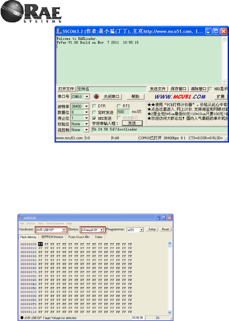
should reset modem to distinguish whether it print startup message. When this modem have RAELoader, reset
may cause modem toggle LED1 and print startup message as below:
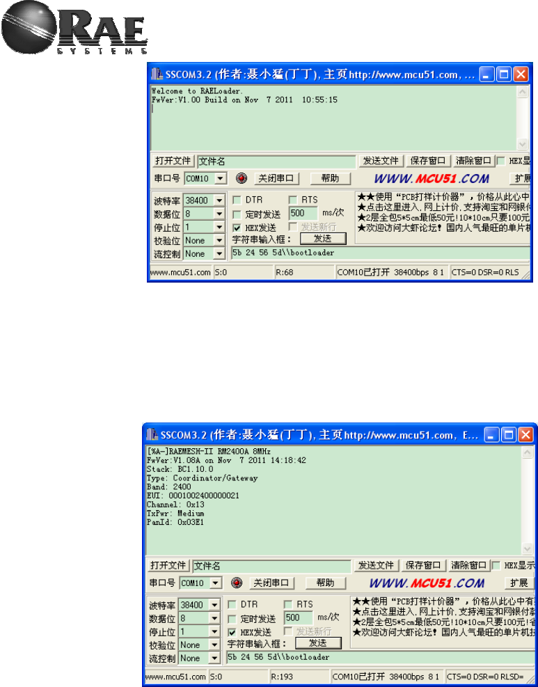
For Internal Use Only
If there is not any phenomenon on LED1 and USART after reset modem, this modem embed Atmel bootloader.
b) Bootloader and application mixed
If modem have bootloader and application in corresponding flash memory, using above method is useless. We
can use SET_BOOTLOADER(0x5B 24 56 5D) to distinguish.
First, send SET_BOOTLOADER through USART port to modem.
Then, if modem reset and print startup menu of application as below, this modem embed Atmel bootloader.
If modem print startup menu of RAELoader as below and toggle LED1 very quickly, this modem embed
RAELoader.
For Internal Use Only
2) How to embed RAELoader_ATMega1281
If you want to embed bootloader into RM900 or RM2400A which use ATMega1281 as mcu, no matter Atmel
bootloader or RAELoader, you should prepare corresponding tool.
Software: AVRUSB V2.0.2.231
Hardware: AVRUSB Programmer and RAEMeshII Dev board.
Then, operate step by step as below,
a) Make sure the correct hardware selected
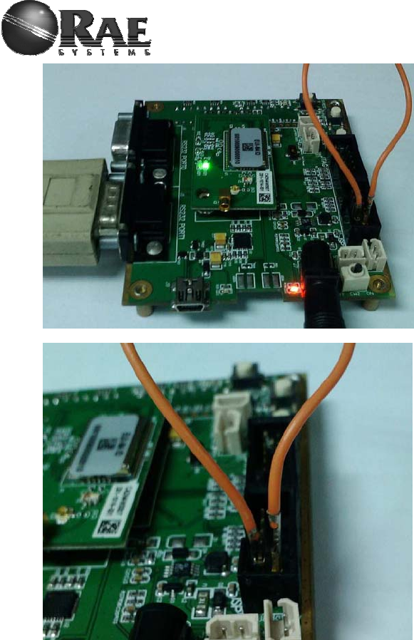
b) Make sure the AVRUSB connected to dev board and board is power on, click “Reset”.
If a green label is at bottom of AVRUSB framework, go to next step.
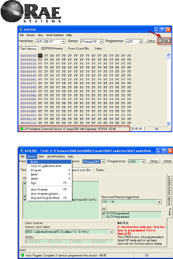
For Internal Use Only
c) Erase target MCU
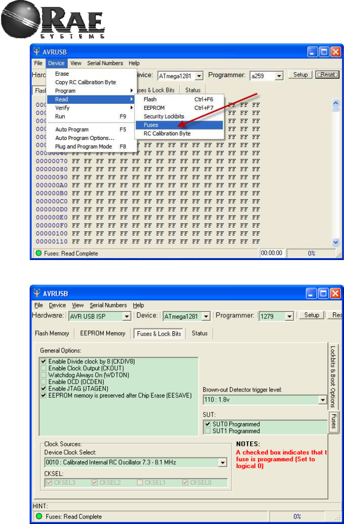
d) Read out current fuse setting.
If you want to embed Atmel bootloader, please go to Step e).
If you want to embed RAELoader, please go to Step f).
For Internal Use Only
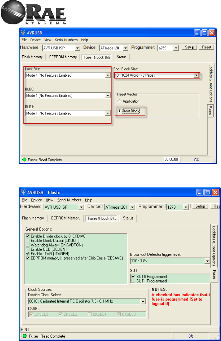
e) Check the following setting, it’s used for Atmel bootloader
For Internal Use Only
f) Check the following settings and make sure as same as showed.
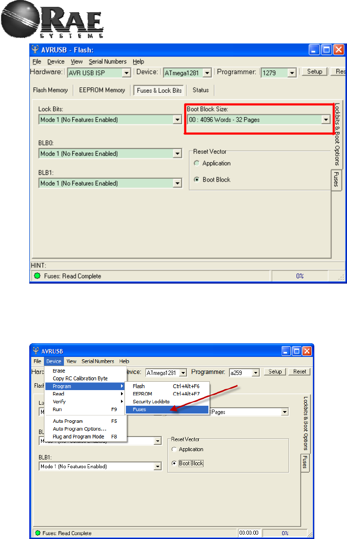
Caution: RAELoader ATmega1281’s Boot Block Size should be 4096 bytes.
For Internal Use Only
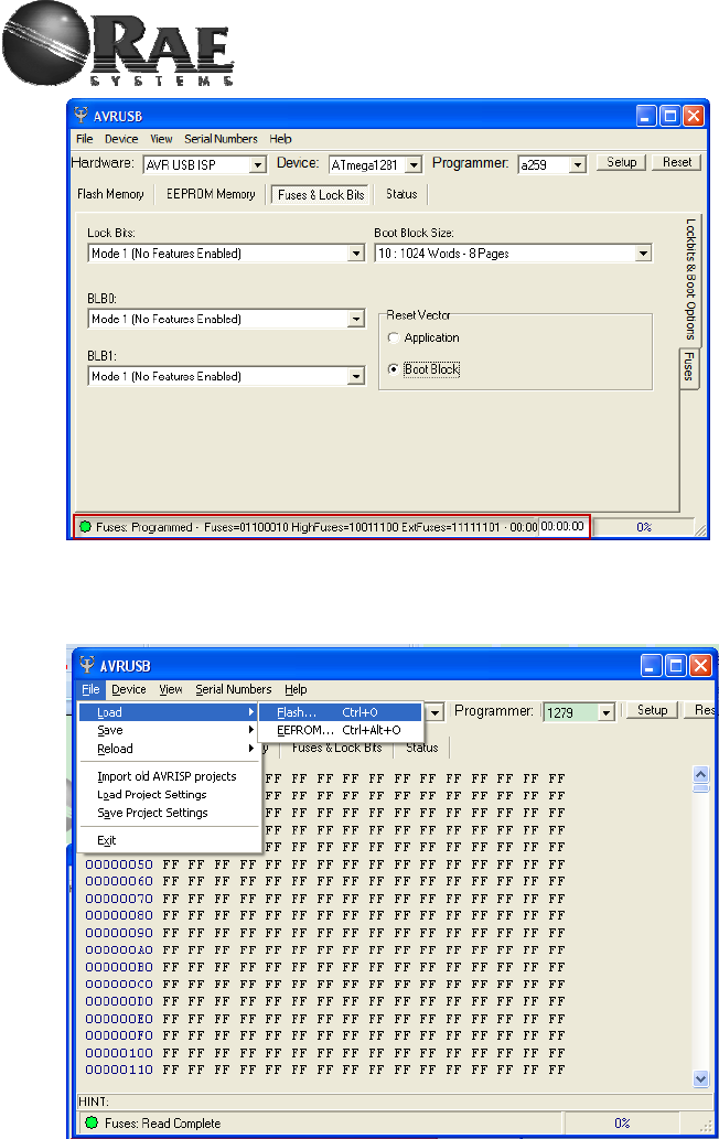
g) Write back Fuse setting if any changes made, make sure program successfully.
If you want to embed Atmel bootloader, please go to Step h).
If you want to embed RAELoader, please go to Step i).
For Internal Use Only
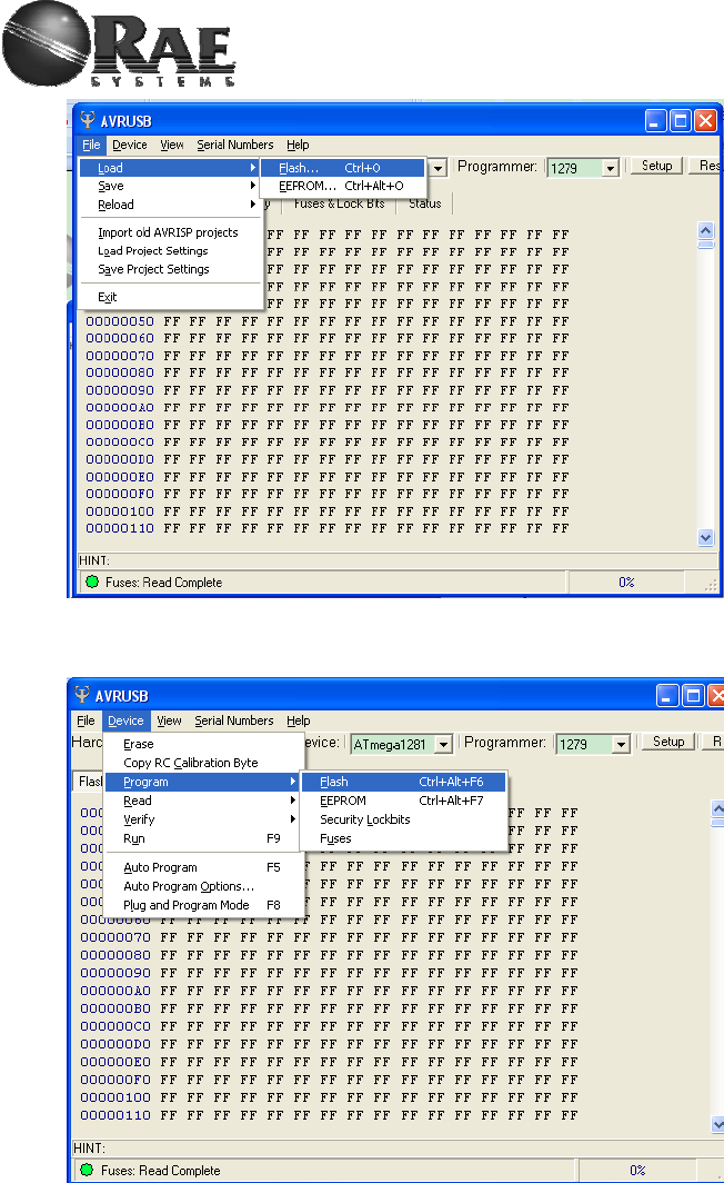
h) Load ATMEL bootloader hex image.
Find corresponding path and load *.hex which should be written into boot flash memory.
i) Load RAELoader hex image.
Find corresponding path and load *.hex which should be written into flash merory.
For Internal Use Only
j) Press Device -> Program -> Flash, load bootloader image successfully.
For Internal Use Only
3) How to embed RAELoader_Sam7x
If you want to embed bootloader into RM900A which use AT91SAM7X256 as mcu, you should prepare
corresponding tool.
Software: SEGGER J-Flash ARM V4.20
Hardware: JLINK ARM Programmer and RAEMeshII Dev board.
Then, operate step by step as below,
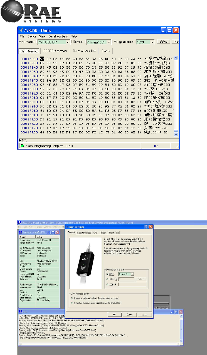
a) open J-Flash ARM and press “Alt + F7”, you will see this window:

For Internal Use Only
b) click “CPU” and choose AT91SAM7X256 as device.
c) put RM900A on dev board and use JLINK to connect with it.
d) click “File” ->”Open data file” to choose RAELoader_Sam7x *.hex file.
For Internal Use Only
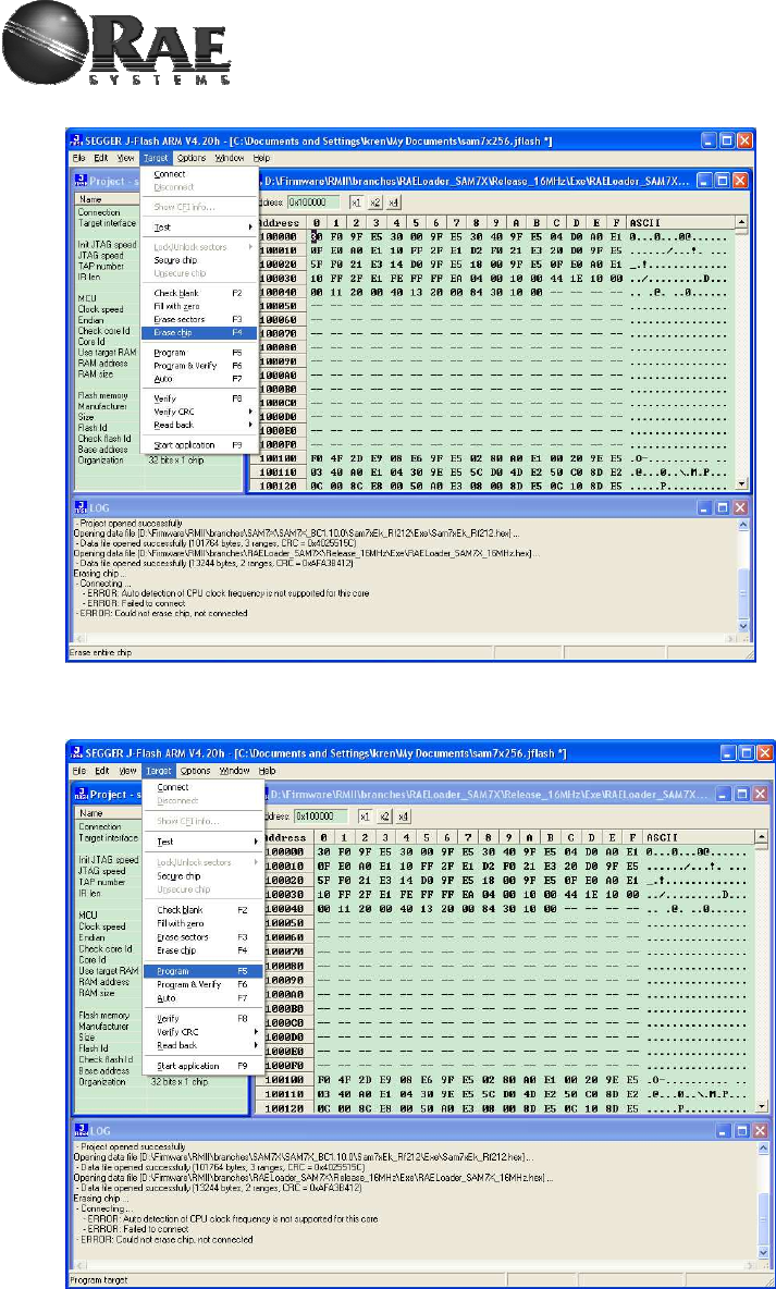
e) click “Target” -> “Erase chip” to erase all flash memory.
f) click “Target” -> “Program” to downloader RAELoader hex file into mcu.
For Internal Use Only
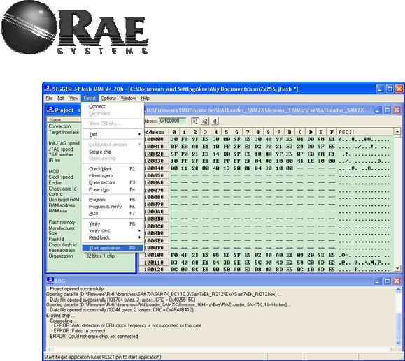
g) click “Target” -> “Start application” to make mcu run.
h) Then, embed RAELoader_Sam7x is successful, go to Section4.
4) Firmware Upgrade
User should use different utility to upgrade RAEMeshII application firmware.
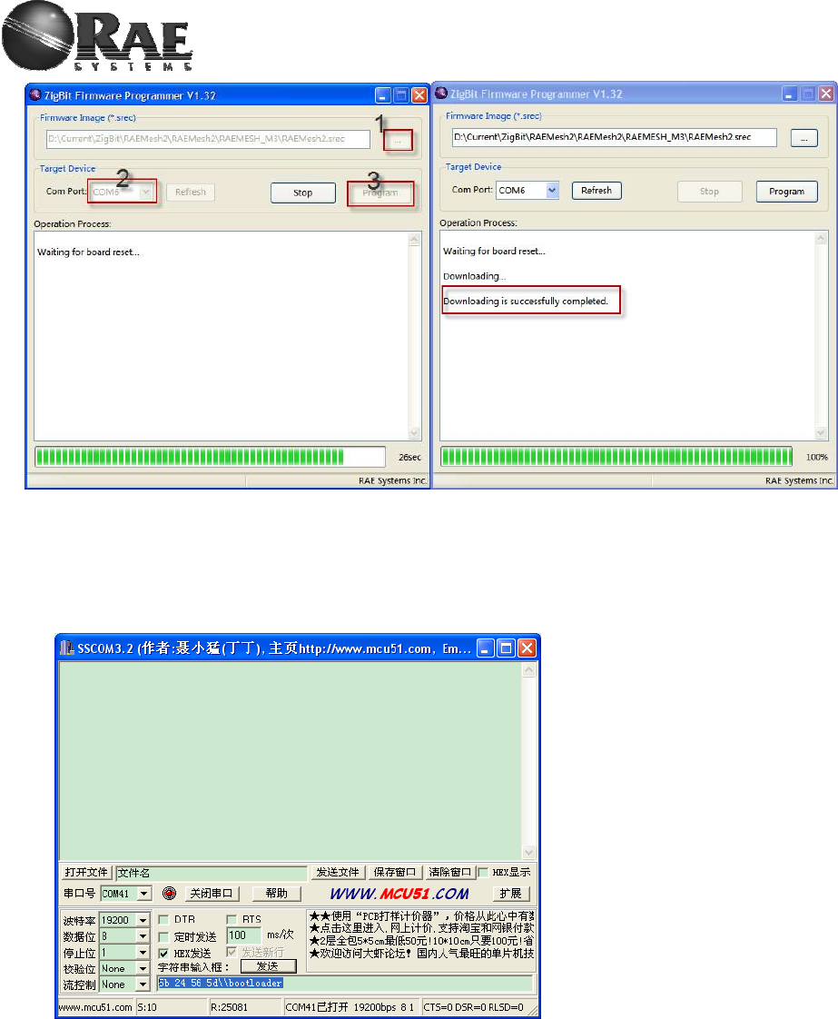
a) Using Atmel bootloader to upgrade
1. Select firmware file, *.srec
2. Select correct com port
3. Click “Program”, then Reset RAEMesh2 module in 30 seconds
Waiting for program successful.
For Internal Use Only
b) Using RAELoader to upgrade
1. Use RMCI command to access RAELoader
If modem run app firmware, we can use RMCI command, 0x5b 24 56 5d, to access RAELoader for firmware
upgrade.
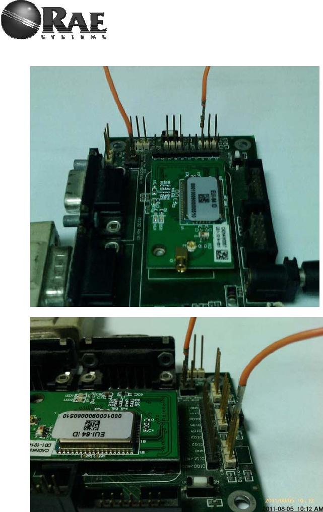
2. Use jumper to access RAELoader
We can use hardware jumper to access RAELoader. First, jump specified pin to ground; second, press reset
button on evaluation board to reset modem; then modem access into RAELoader.
For Internal Use Only
Now, we have two type of evaluation board, please use following method for loader jumper. Old evaluation board
setup, it is the same with how to set ZcoRAE-M3 into bootloader.
New evaluation board setup
For Internal Use Only
3. RAELoader Indication
RAELoader use LEDs blink and toggle on M3 adapter or evaluation board to tell user the situation of loader.
When modem access into RAELoader, one LED, which lable is LED2 on M3 adapter, will blink continuously. If start to
upgrade firmware, two LEDs on evaluation board will blink continuously and alternately.
4. Upgrade
When modem is in RAELoader, we use RAEProgrammer4000 to upgrade firmware, detail please refer to user
guide of RAEProgrammer4000.
5. Quit
if modem access into RAELoader using RMCI command, reset or upgrade successfully can make modem out.

For Internal Use Only
6. Terms
GTW: A RTR used for gateway. Only one GTW per network.
RTR: Full Function Device. Sensor node with routing ability. RTR requires line power all time.
STD: Reduce Function Device. A Sleeping node can only talk to a RTR or GTW. Can not relay the message. Can be a
battery powered device.
RCM :Radio Communications Module
RDTE: Reader Data Terminal Equipment.
RMCI: RAEMesh Module Command Interface.
SDTE : Sensor Data Terminal Equipment.
7. Reference
Atmel:
FCC: www.gcc.gov
Zigbee Alliance: www.zigbee.org
8. Contact
Developer: Kai Ren
Tel:021-69522616 Ext4115
Email: kren@raesystems.com
9. Disclaimer
Product and Company names and logos referenced may either be trademarks or registered trademarks of their respective
companies. We reserve the right to make modifications and/or improvements without prior notification. All information is
correct at time of issue. RAE Systems does not convey any license under its patent rights or assume any responsibility for
the use of the described product.
10. Warnings
FCC Notifications:
Compliance Statement (Part 15.19)
This device complies with part 15 of the FCC rules. Operation is subject to the following two
conditions:
1. This device may not cause harmful interference received, including interference
that may cause undesired operation.
2. This device must accept any interference received, including interference that may
cause undesired operation.
Warning (Part 15.21)
Changes or modifications not expressly approved by the party responsible for compliance

For Internal Use Only
could void the user’s authority to operate the equipment.
This device must be operated as supplied by Raesystems. Any changes or
modifications made to the device can be jeopardize, but there is one
exception. The radio’s antenna can be replaced as long as the specification of the
antenna matches the original.
This equipment has been tested and found to comply with the limits for
a Class B digital device, pursuant to part 15 of the FCC Rules. These
limits are designed to provide reasonable protection against harmful
interference in a residential installation. This equipment generates
uses and can radiate radio frequency energy and, if not installed and
used in accordance with the instructions, may cause harmful interference
to radio communications. However, there is no guarantee that interference
will not occur in a particular installation. If this equipment does cause
harmful interference to radio or television reception, which can be
determined by turning the equipment off and on, the user is encouraged
to try to correct the interference by one or more of the following
measures:
-Reorient or relocate the receiving antenna.
-Increase the separation between the equipment and receiver.
-Connect the equipment into an outlet on a circuit different from that
to which the receiver is connected.
-Consult the dealer or an experienced radio/TV technician for help.
Information for the OEM Integrators
This device is intended for OEM integrators only. Please see the full grant of
equipment document for restrictions.
Label Information to the End User by the OEM or Integrators
If the FCC ID of this module is not visible when it is installed inside another device,
then the outside of the device into which the module is installed must be label with
"Contains FCC ID: SU3RM900".