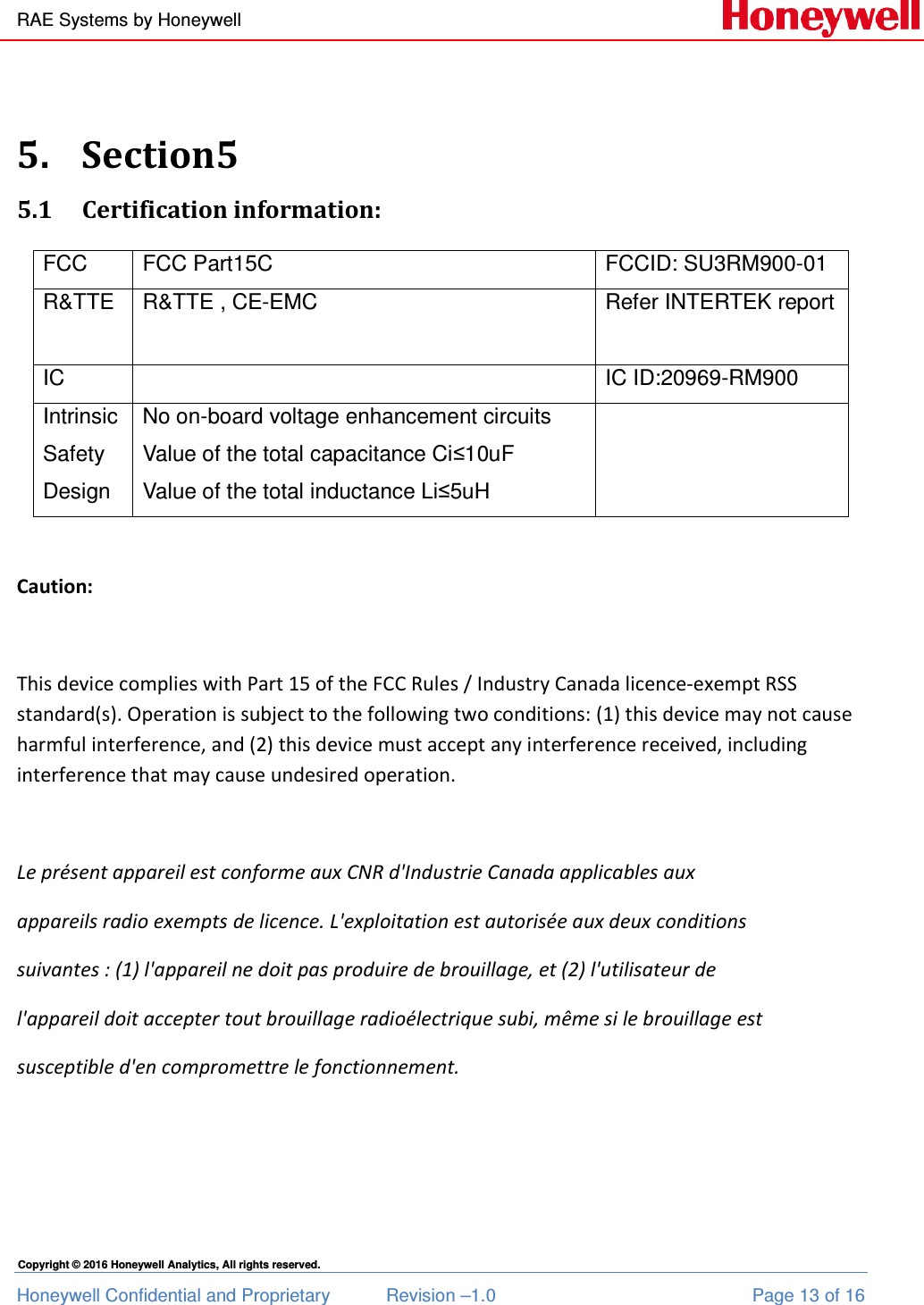
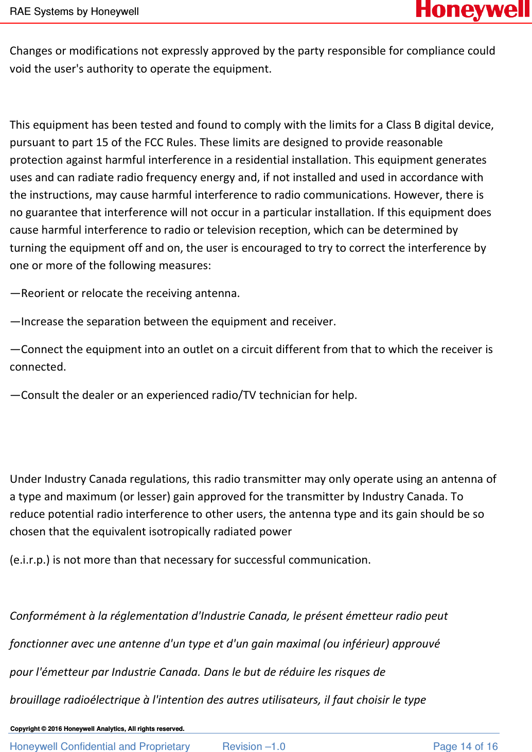
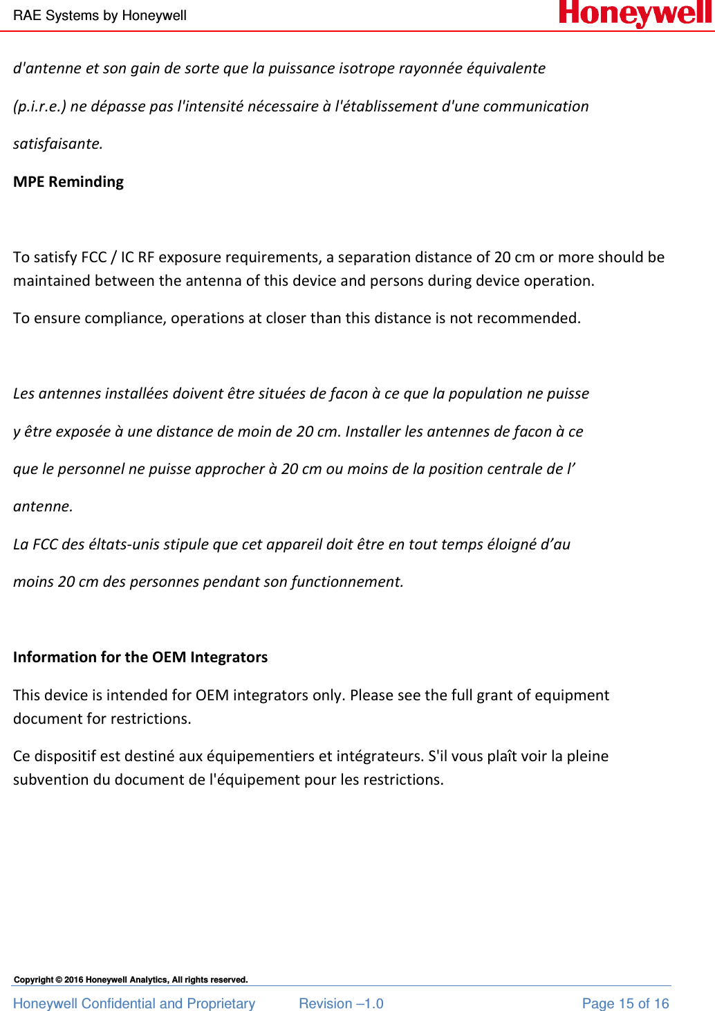
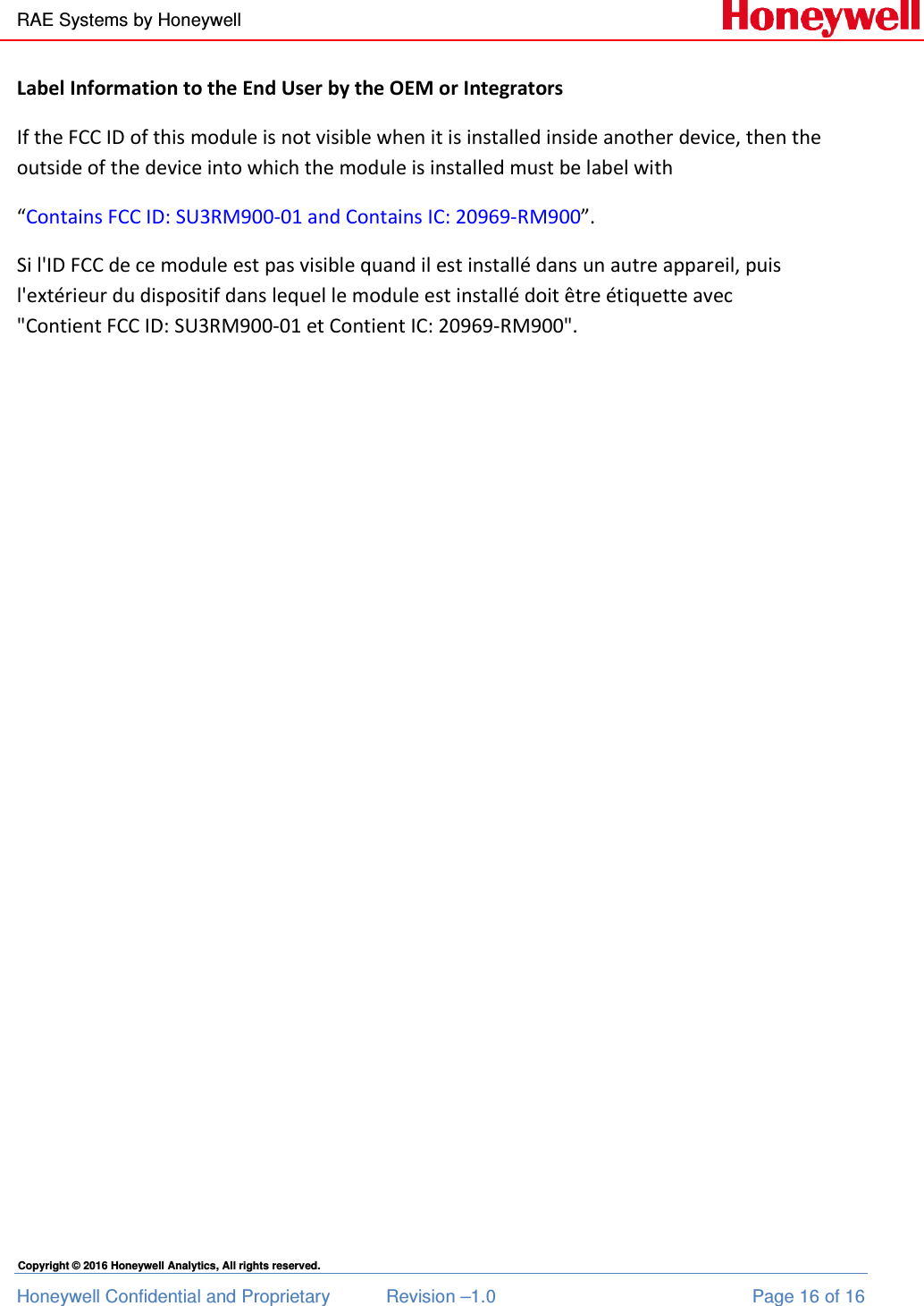
RAE Systems RM900-01 RAE Mesh module User Manual uesr manual

RAE Systems, Inc RAE Mesh module uesr manual

uesr manual

RAE Systems by Honeywell Honeywell Confidential and Proprietary  Revision –1.0  Page 1 of 16 Copyright © 2016 Honeywell Analytics, All rights reserved.  RAEMesh Sub 1G wireless modem RM900       Document Information Info  Content Author(s)  Su Feng Revision  1.0 Document Status  First release Date   Apr 5, 2016 Distribution  Internal Use Only Approvals     Name  Date  Signature James Liu       Zhao Pengjun
RAE Systems by Honeywell Honeywell Confidential and Proprietary  Revision –1.0  Page 2 of 16 Copyright © 2016 Honeywell Analytics, All rights reserved.               Release Histroy Rev.  Date  Author  Descripition 1.0  Apr. 5 2016  Su Feng  Initial draft
RAE Systems by Honeywell Honeywell Confidential and Proprietary  Revision –1.0  Page 3 of 16 Copyright © 2016 Honeywell Analytics, All rights reserved.    Contents 1.  Section1: ......................................................................................................................................... 4 1.1 Summary: .......................................................................................................................... 4 1.2 Key Features: .................................................................................................................... 4 2.  Section2: ......................................................................................................................................... 5 2.1 Technical Description: ..................................................................................................... 5 3.  Section3: ......................................................................................................................................... 6 3.1 Modem Characteristics: ................................................................................................... 6 3.2 PIN Description: ................................................................................................................ 7 3.3 Physical Characteristics:.................................................................................................. 8 4.  Section4: ......................................................................................................................................... 9 4.1 Typical Application diagram: .......................................................................................... 9 4.2 Mounting Information: .................................................................................................... 9 4.3 Antenna Reference: ........................................................................................................ 10 5.  Section5: ....................................................................................................................................... 11 5.1 Certification Information: ............................................................................................. 11 5.2 Modem Information: ...................................................................................................... 11
RAE Systems by Honeywell Honeywell Confidential and Proprietary  Revision –1.0  Page 4 of 16 Copyright © 2016 Honeywell Analytics, All rights reserved. 1. Section1: 1.1 Summary: RM900 is a high-sensitivity Sub 1GHz IEEE 802.15.4 module, which offers a complete microcontroller/transceiver solution containing all hardware features necessary for development of wireless application. It will replace old Atmel RM900, which is obsolete now. 1.2 Key Features: • Frequency Band  779  to  787MHz, 863  to  870MHz,  902  to 928MHz • Power        1.8 ~ 3.6V, typical 3.3V • Interfaces        48-pin  • RF  20kbps  BPSK/OQPSK  in  868MHz,  40kbps BPSK/OQPSK in 915MHz  • Dimensions       18.8 x 13.5 x 3.0 mm • Antenna Interface      100-Ohm for balanced output • Operating Temperature Range   -40ºC to +60ºC • Indicators         Two LEDs, one red, one yellow (DS1, DS2) • Current Consumption     Sleep current < 40uA 50mA TX @ 10dBm 8MHz Crystal @ 25℃ 15mA RX @ 8MHz Crystal • RF receive sensitivity                 -102dBm at 1% packet error rate for a payload of 20 bytes. • FCC and CE compliant • RoHS compliant
RAE Systems by Honeywell Honeywell Confidential and Proprietary  Revision –1.0  Page 5 of 16 Copyright © 2016 Honeywell Analytics, All rights reserved. 2. Section2: 2.1 Technical Description: RM900 can work at 868MHz, 1 channel, channel spacing 2MHz. It can also work at 902 ~ 924MHz, 10 channels, channel spacing 2MHz. Users can change its TX power, working channel through com tool. RM900 is a high sensitivity IEEE 802.15.4/ZigBee module. A combination of Atmel’s MCU SMD21 and RF transceiver AT86RF212B, the RM900 offers superior radio performance.  The module contains Atmel’s SAMD21 Cotex-M0 Microcontroller, AT86RF212B RF transceiver. The module can be easily mounted on a simple 2-layer PCB with a minimum of required external connection. Neither via-holes nor wires are allowed on the PCB upper layer in area occupied by the module. As a critical requirement, RF_GND pins should be grounded via several holes to be located right next to the pins thus minimizing inductance and preventing both mismatch and losses.
RAE Systems by Honeywell Honeywell Confidential and Proprietary  Revision –1.0  Page 6 of 16 Copyright © 2016 Honeywell Analytics, All rights reserved. 3. Section3: 3.1 Modem Characteristics: 3.1.1 Electric Characteristics Test conditions (unless otherwise stated), Vcc=3.3V, Tamb=25°C Parameters  Range  Unit Condition VCC  1.8 ~ 3.6 V   Current Consumption: RX mode  15  mA  @8MHz Current Consumption: TX mode  50  mA  @10dBm 8MHz Current Consumption: Sleep mode  30  uA   3.1.2 RF Characteristics:  Parameters  Range  Unit  Condition Frequency Band  868/902~924  MHz   Number of Channel  1/10    Channel Spacing  2  MHz   Transmitter Output Power +10 +6 +0 dBm High Medium Low Receiver Sensitivity  -102  dBm  PER=1%, PSDU=20 byte On-Air Data Rate  20/40  kbps  O-QPSK TX output/RX input Nominal Impedance  100  Ω  Balanced output PCB antenna  0  dBi  Gain Omni antenna  3  dBi  Gain
RAE Systems by Honeywell Honeywell Confidential and Proprietary  Revision –1.0  Page 7 of 16 Copyright © 2016 Honeywell Analytics, All rights reserved.
RAE Systems by Honeywell Honeywell Confidential and Proprietary  Revision –1.0  Page 8 of 16 Copyright © 2016 Honeywell Analytics, All rights reserved. 3.1.3 Module Interfaces characteristics Parameters  Range  Unit  Condition UART Maximum Baud Rate  38.4  kbps   GPIO Output Voltage (VOH/VOL)  0.7VCC/ 0.2VCC  V  -10/ 5mA VCC = 3.3V GPIO Input Voltage (VIH/VIL)  0.7VCC/0.2VCC  V   Real Time Oscillator Frequency  32.768  kHz   3.2 PIN Description:
RAE Systems by Honeywell Honeywell Confidential and Proprietary  Revision –1.0  Page 9 of 16 Copyright © 2016 Honeywell Analytics, All rights reserved. PIN description: PIN Pin Name Description I/O 4  GPIO_LED_R  General Purpose Digital Output  O 6  GPIO_LED_G  General Purpose Digital Output  O 8  RESET  Reset Input (active low)  9,22,23  DGND  Digital Ground  13  UART_RXD  UART receive input  I 14  UART_TXD  UART transmit output  O 24,25  D_VCC  Digital Supply Voltage (Vcc)   26  SWDIO  JTAG Serial Wire Debug Interface  I/O 29  SWCLK  JTAG Serial Wire Debug Interface  I/O 34  A_VREF  Input/Output reference voltage for ADC  I/O 35  A_GND  Analog ground  40  CTX  RF RX/TX Indication to control an external RF front-end  O 41  CRX  RF RX/TX Indication to control an external RF front-end  O 43  WakeUp  Wake Up Input(active low)  I 44,46,48  RF_GND  RF Analog Ground   45  RFP_IO  Differential RF Input/Output  I/O 47  RFN_IO  Differential RF Input/Output  I/O Others pins  Reserved
RAE Systems by Honeywell Honeywell Confidential and Proprietary  Revision –1.0  Page 10 of 16 Copyright © 2016 Honeywell Analytics, All rights reserved. 3.3 Physical Characteristics Parameter  Range  Unit  Condition Size 18.8 x 13.5 x 3  mm  Operation Temperature Range -40 to +60   Operation Relative Humidity Range No more than 80%    Mechanical drawing, unit: mm  Top View          Side View
RAE Systems by Honeywell Honeywell Confidential and Proprietary  Revision –1.0  Page 11 of 16 Copyright © 2016 Honeywell Analytics, All rights reserved.  4. Section4 4.1 Typical Application diagram  PIN  PIN Name  Definition  I/O 8  RESET  Reset pin, low active  Input 13  UART_RXD UART TXD pin  Output 14  UART_TXD UART RXD pin  Input 43  WakeUp  Low level wake-up High level to sleep  Input 24/25  VCC     9/22/23 GND
RAE Systems by Honeywell Honeywell Confidential and Proprietary  Revision –1.0  Page 12 of 16 Copyright © 2016 Honeywell Analytics, All rights reserved.  4.2 Mounting Information The below diagram shows the recommended PCB layout for RM900 module.
RAE Systems by Honeywell Honeywell Confidential and Proprietary  Revision –1.0  Page 13 of 16 Copyright © 2016 Honeywell Analytics, All rights reserved.  5. Section5 5.1 Certification information: FCC  FCC Part15C  FCCID: SU3RM900-01 R&TTE  R&TTE , CE-EMC  Refer INTERTEK report  IC    IC ID:20969-RM900 Intrinsic Safety Design No on-board voltage enhancement circuits Value of the total capacitance Ci≤10uF Value of the total inductance Li≤5uH   Caution:  This device complies with Part 15 of the FCC Rules / Industry Canada licence-exempt RSS standard(s). Operation is subject to the following two conditions: (1) this device may not cause harmful interference, and (2) this device must accept any interference received, including interference that may cause undesired operation.  Le présent appareil est conforme aux CNR d'Industrie Canada applicables aux  appareils radio exempts de licence. L'exploitation est autorisée aux deux conditions  suivantes : (1) l'appareil ne doit pas produire de brouillage, et (2) l'utilisateur de  l'appareil doit accepter tout brouillage radioélectrique subi, même si le brouillage est  susceptible d'en compromettre le fonctionnement.
RAE Systems by Honeywell Honeywell Confidential and Proprietary  Revision –1.0  Page 14 of 16 Copyright © 2016 Honeywell Analytics, All rights reserved. Changes or modifications not expressly approved by the party responsible for compliance could void the user's authority to operate the equipment.  This equipment has been tested and found to comply with the limits for a Class B digital device, pursuant to part 15 of the FCC Rules. These limits are designed to provide reasonable protection against harmful interference in a residential installation. This equipment generates uses and can radiate radio frequency energy and, if not installed and used in accordance with the instructions, may cause harmful interference to radio communications. However, there is no guarantee that interference will not occur in a particular installation. If this equipment does cause harmful interference to radio or television reception, which can be determined by turning the equipment off and on, the user is encouraged to try to correct the interference by one or more of the following measures: —Reorient or relocate the receiving antenna. —Increase the separation between the equipment and receiver. —Connect the equipment into an outlet on a circuit different from that to which the receiver is connected. —Consult the dealer or an experienced radio/TV technician for help.   Under Industry Canada regulations, this radio transmitter may only operate using an antenna of a type and maximum (or lesser) gain approved for the transmitter by Industry Canada. To reduce potential radio interference to other users, the antenna type and its gain should be so chosen that the equivalent isotropically radiated power  (e.i.r.p.) is not more than that necessary for successful communication.   Conformément à la réglementation d'Industrie Canada, le présent émetteur radio peut fonctionner avec une antenne d'un type et d'un gain maximal (ou inférieur) approuvé  pour l'émetteur par Industrie Canada. Dans le but de réduire les risques de  brouillage radioélectrique à l'intention des autres utilisateurs, il faut choisir le type
RAE Systems by Honeywell Honeywell Confidential and Proprietary  Revision –1.0  Page 15 of 16 Copyright © 2016 Honeywell Analytics, All rights reserved. d'antenne et son gain de sorte que la puissance isotrope rayonnée équivalente  (p.i.r.e.) ne dépasse pas l'intensité nécessaire à l'établissement d'une communication  satisfaisante. MPE Reminding  To satisfy FCC / IC RF exposure requirements, a separation distance of 20 cm or more should be maintained between the antenna of this device and persons during device operation. To ensure compliance, operations at closer than this distance is not recommended.   Les antennes installées doivent être situées de facon à ce que la population ne puisse  y être exposée à une distance de moin de 20 cm. Installer les antennes de facon à ce  que le personnel ne puisse approcher à 20 cm ou moins de la position centrale de l’  antenne. La FCC des éltats-unis stipule que cet appareil doit être en tout temps éloigné d’au  moins 20 cm des personnes pendant son functionnement.  Information for the OEM Integrators This device is intended for OEM integrators only. Please see the full grant of equipment document for restrictions. Ce dispositif est destiné aux équipementiers et intégrateurs. S'il vous plaît voir la pleine subvention du document de l'équipement pour les restrictions.
RAE Systems by Honeywell Honeywell Confidential and Proprietary  Revision –1.0  Page 16 of 16 Copyright © 2016 Honeywell Analytics, All rights reserved. Label Information to the End User by the OEM or Integrators If the FCC ID of this module is not visible when it is installed inside another device, then the outside of the device into which the module is installed must be label with  “Contains FCC ID: SU3RM900-01 and Contains IC: 20969-RM900”. Si l'ID FCC de ce module est pas visible quand il est installé dans un autre appareil, puis l'extérieur du dispositif dans lequel le module est installé doit être étiquette avec "Contient FCC ID: SU3RM900-01 et Contient IC: 20969-RM900".

Navigation menu