RAE Systems RMWIFI-QC RMWIFI-QC (WIFI Module) User Manual
RAE Systems, Inc RMWIFI-QC (WIFI Module)
UserManual.wiki
>
RAE Systems
>
RMWIFI-QC User Manual
>
User Manual
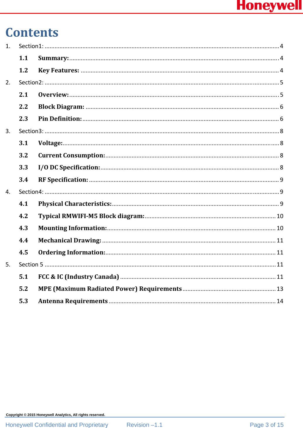
Contents
1.
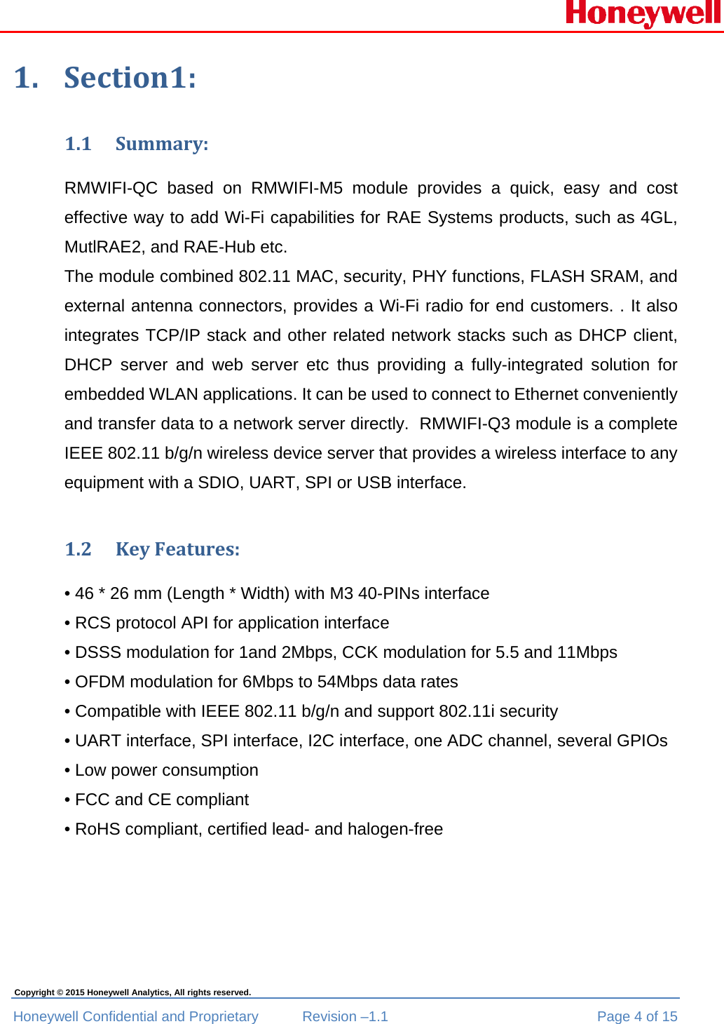
User Manual
2.
Users manual
User Manual
Navigation menu
Upload a User Manual
Namespaces
Wiki Guide
HTML
PDF
Info
Views
User Manual
Discussion / Help
Navigation