RAE Systems RMWIFI-QC RMWIFI-QC (WIFI Module) User Manual
RAE Systems, Inc RMWIFI-QC (WIFI Module)
Contents
- 1. User Manual
- 2. Users manual
User Manual

Honeywell Confidential and Proprietary Revision –1.1 Page 1 of 15
Copyright © 2015 Honeywell Analytics, All rights reserved.
ULTRA LOW-POWER WIRELESS
RMWIFI-QC
Document Information
Info Content
Author(s) Manish Bhakuni
Revision 1.1
Document Status Draft
Date March 7, 2016
Distribution Restricted
Approvals
Name Date Signature
R, Gopalakrishnan(Gopal)

Honeywell Confidential and Proprietary Revision –1.1 Page 2 of 15
Copyright © 2015 Honeywell Analytics, All rights reserved.
Release Histroy
Rev. Date Author Descripition
1.0 October 20, 2015 Manish Bhakuni Initial draft
1.1 March 7, 2016 Sarang Gulhane Declaration for FCC & IC ,
Recommended by Intertek, China
(Certification Agency)

Honeywell Confidential and Proprietary Revision –1.1 Page 3 of 15
Copyright © 2015 Honeywell Analytics, All rights reserved.
Contents
1.Section1:...............................................................................................................................................4
1.1Summary:................................................................................................................................4
1.2KeyFeatures:.........................................................................................................................4
2.Section2:...............................................................................................................................................5
2.1Overview:................................................................................................................................5
2.2BlockDiagram:......................................................................................................................6
2.3PinDefinition:........................................................................................................................6
3.Section3:...............................................................................................................................................8
3.1Voltage:....................................................................................................................................8
3.2CurrentConsumption:..........................................................................................................8
3.3I/ODCSpecification:.............................................................................................................8
3.4RFSpecification:....................................................................................................................9
4.Section4:...............................................................................................................................................9
4.1PhysicalCharacteristics:......................................................................................................9
4.2TypicalRMWIFI‐M5Blockdiagram:................................................................................10
4.3MountingInformation:.......................................................................................................10
4.4MechanicalDrawing:..........................................................................................................11
4.5OrderingInformation:........................................................................................................11
5.Section5.............................................................................................................................................11
5.1FCC&IC(IndustryCanada)...............................................................................................11
5.2MPE(MaximumRadiatedPower)Requirements.........................................................13
5.3AntennaRequirements......................................................................................................14

Honeywell Confidential and Proprietary Revision –1.1 Page 4 of 15
Copyright © 2015 Honeywell Analytics, All rights reserved.
1. Section1:
1.1 Summary:
RMWIFI-QC based on RMWIFI-M5 module provides a quick, easy and cost
effective way to add Wi-Fi capabilities for RAE Systems products, such as 4GL,
MutlRAE2, and RAE-Hub etc.
The module combined 802.11 MAC, security, PHY functions, FLASH SRAM, and
external antenna connectors, provides a Wi-Fi radio for end customers. . It also
integrates TCP/IP stack and other related network stacks such as DHCP client,
DHCP server and web server etc thus providing a fully-integrated solution for
embedded WLAN applications. It can be used to connect to Ethernet conveniently
and transfer data to a network server directly. RMWIFI-Q3 module is a complete
IEEE 802.11 b/g/n wireless device server that provides a wireless interface to any
equipment with a SDIO, UART, SPI or USB interface.
1.2 KeyFeatures:
• 46 * 26 mm (Length * Width) with M3 40-PINs interface
• RCS protocol API for application interface
• DSSS modulation for 1and 2Mbps, CCK modulation for 5.5 and 11Mbps
• OFDM modulation for 6Mbps to 54Mbps data rates
• Compatible with IEEE 802.11 b/g/n and support 802.11i security
• UART interface, SPI interface, I2C interface, one ADC channel, several GPIOs
• Low power consumption
• FCC and CE compliant
• RoHS compliant, certified lead- and halogen-free

Honeywell Confidential and Proprietary Revision –1.1 Page 5 of 15
Copyright © 2015 Honeywell Analytics, All rights reserved.
2. Section2:
2.1 Overview:
RMWIFI-QC operates in the unlicensed 2.4 radio bands IEEE 802.11b/g, which
supports Direct Sequence Spread Spectrum (DSSS) 1 Mb/s and 2 Mb/s data rates,
Complementary Code Keyed (CCK) 5.5 Mb/s and 11 Mb/s data rates and 6Mb/s
to 54Mb/s OFDM .
RMWIFI-QC is based on RMWIFI-M5 module, which contains QC 4004A WIFI
system-on-chip. The QC 4004A have fully integrated RF Transceiver, low power
PA and application processor. Both TX and RX chain in the module incorporate
internal power control loops.
RMWIFI-QC carries onboard single supply monitor for 1.8V voltage supply with
optional module controlled external regulator enable control pin.
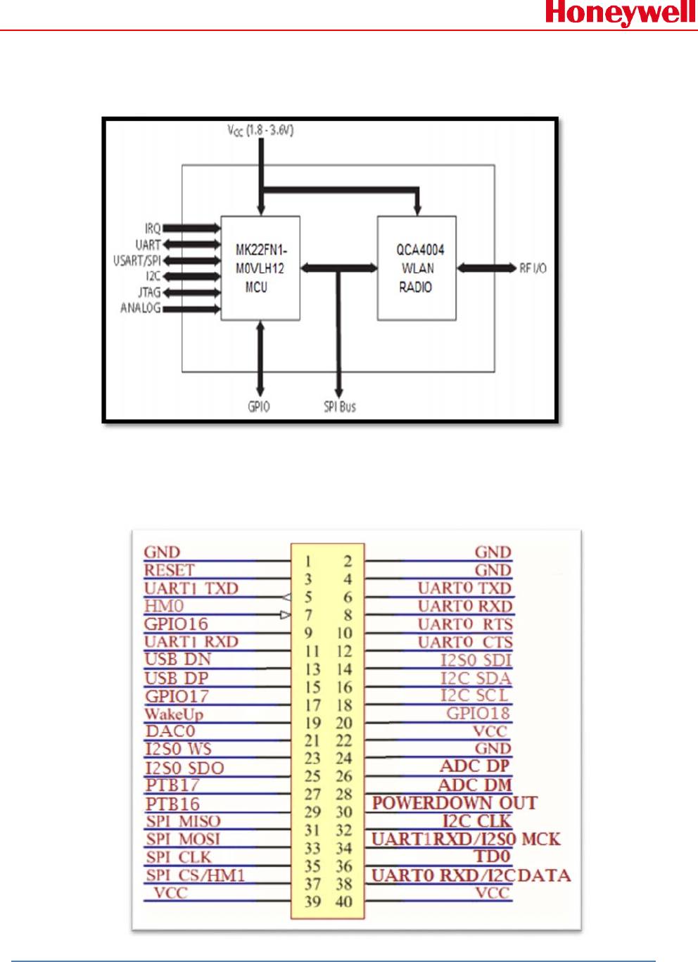
The module contains MK22FN1M0VLH12 Microcontroller and QCA4004 Radio.
The QCA4004 single-chip Radio provides a complete 2.4 GHZ & 5 GHz radio
interface between the antenna and the microcontroller. It comprises the analog
radio part, digital modulation and demodulation including time and frequency
synchronization, as well as data buffering. The differential to single ended TX &
RX path conversion is done using lumped balun. Antenna is connected to TX &
RX path using external 2.4 GHz antenna switch. 5 GHz part of the radio is disabled
and not used in this module.
Honeywell Confidential and Proprietary Revision –1.1 Page 6 of 15
Copyright © 2015 Honeywell Analytics, All rights reserved.
2.2 BlockDiagram:
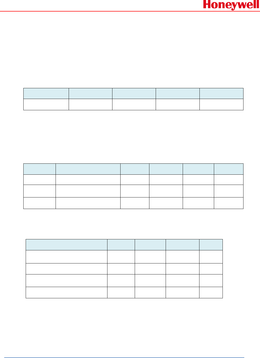
2.3 PinDefinition:

Honeywell Confidential and Proprietary Revision –1.1 Page 7 of 15
Copyright © 2015 Honeywell Analytics, All rights reserved.
Connector
Pin
Pin Name DescriptionI/O
1,2,4,24 GND Ground
3 RESET Active-low system reset for
Micro I
5 UART1_TXD UART1 transmit output O
7 HM0/Bootstrap Enable/Disable into boot load /
UART receive I
9 GPIO16 General purpose IO I/O
11 UART1_RXD UART1 receive input I
13 USB_DN USB Data Minus I/O
15 USB_DP USB Data Plus I/O
17 GPIO17 General purpose IO I/O
19 WakeUp I/O
21 DAC0 DAC Input I/O
23 I2S0_WS I2S0 Word select I/0
25 I2S0_SDO I2S0 serial data output O
27 PTB17 GPIO I/O
29 PTB16 GPIO I/O
31 SPI_MISO Slave SPI master in slave out
line I/O
33 SPI_MOSI Slave SPI master out slave in
line I/O
35 SPI_CLK Slave SPI clock line I
37 SPI_CS/HM1 Slave SPI chip select line/
Enable/Disable into boot load I
22,39,40 VCC Power Supply to module
6 UART0_TXD UART0 transmit output O
8 UART0_RXD UART0 receive input I
10 UART0_RTS RTS input (Request To Send) for
UART hardware flow control I/O
12 UART0_CTS CTS output (Clear To Send) for
UART hardware flow control I/O
14 I2S0_SDI I2S0 Serial data input I
16 I2C_SDA I2C Serial data I/O
18 I2C_SCL I2C Serial clock I/O
20 GPIO18 GPIO I/O
26 ADC_DP ADC Data line to micro I/O
28 ADC_DM ADC Data line to micro I/O
30 POWERDOWN_OUT
32 I2C_CLK I2C Clock I/O
34 UART1_RXD UART1 receive input I
36 TD0
38 UART0_RXD / I2C
Data UART0 receive input / I2C Serial
Data I, I/O
Honeywell Confidential and Proprietary Revision –1.1 Page 8 of 15
Copyright © 2015 Honeywell Analytics, All rights reserved.
3. Section3:
3.1 Voltage:
Power supply for the RMWIFI-M3 module will be provided by the host power
pins.
Symbol Min Typ Max Unit
VCC 2.7 3.3 3.6 V
3.2 CurrentConsumption:
Condition: 25deg.C. The default voltage is 3.3V.
Item Condition Min Nom Max Unit
Receive RX 108 mA
Transmit Pout=8dBm 135 mA
Sleep <300 uA
3.3 I/ODCSpecification:
Parameter Symbol Min Max Unit
Input Low Voltage VIL 0.25*VCC V
Input High Voltage VIH 0.8*VCC V
Output Low Voltage VOL 0.4 V
Output High Voltage VOH 0.8*VCC V
Honeywell Confidential and Proprietary Revision –1.1 Page 9 of 15
Copyright © 2015 Honeywell Analytics, All rights reserved.
3.4 RFSpecification:
The RF performance of RMWIFI-QC is given as follows. The default voltage is
3.3V.
Parameter Condition Min Nom Max Unit
Frequency Range 2412 2462 MHz
Channel Space 5 MHz
RX sensitivity PER 10% @ 54Mbps
64QAM -65 dBm
Tx Power 0 14 16 dBm
4. Section4:
4.1 PhysicalCharacteristics:
Parameter Range Unit
Size 46 * 26 * 10 mm
Operation Temperature
Range -40 to +85 °C
Honeywell Confidential and Proprietary Revision –1.1 Page 10 of 15
Copyright © 2015 Honeywell Analytics, All rights reserved.
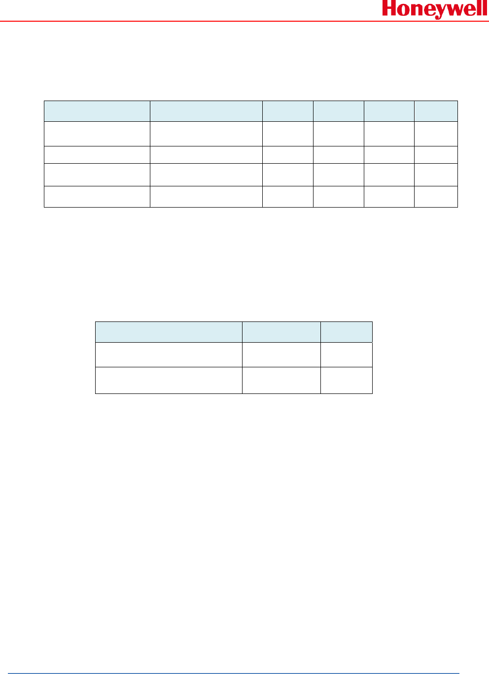
4.2 TypicalRMWIFI‐M5Blockdiagram:
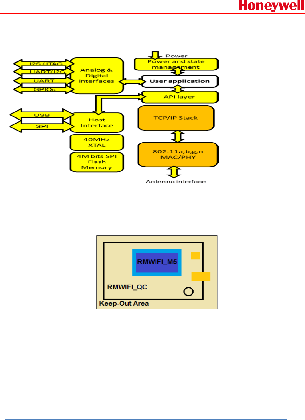
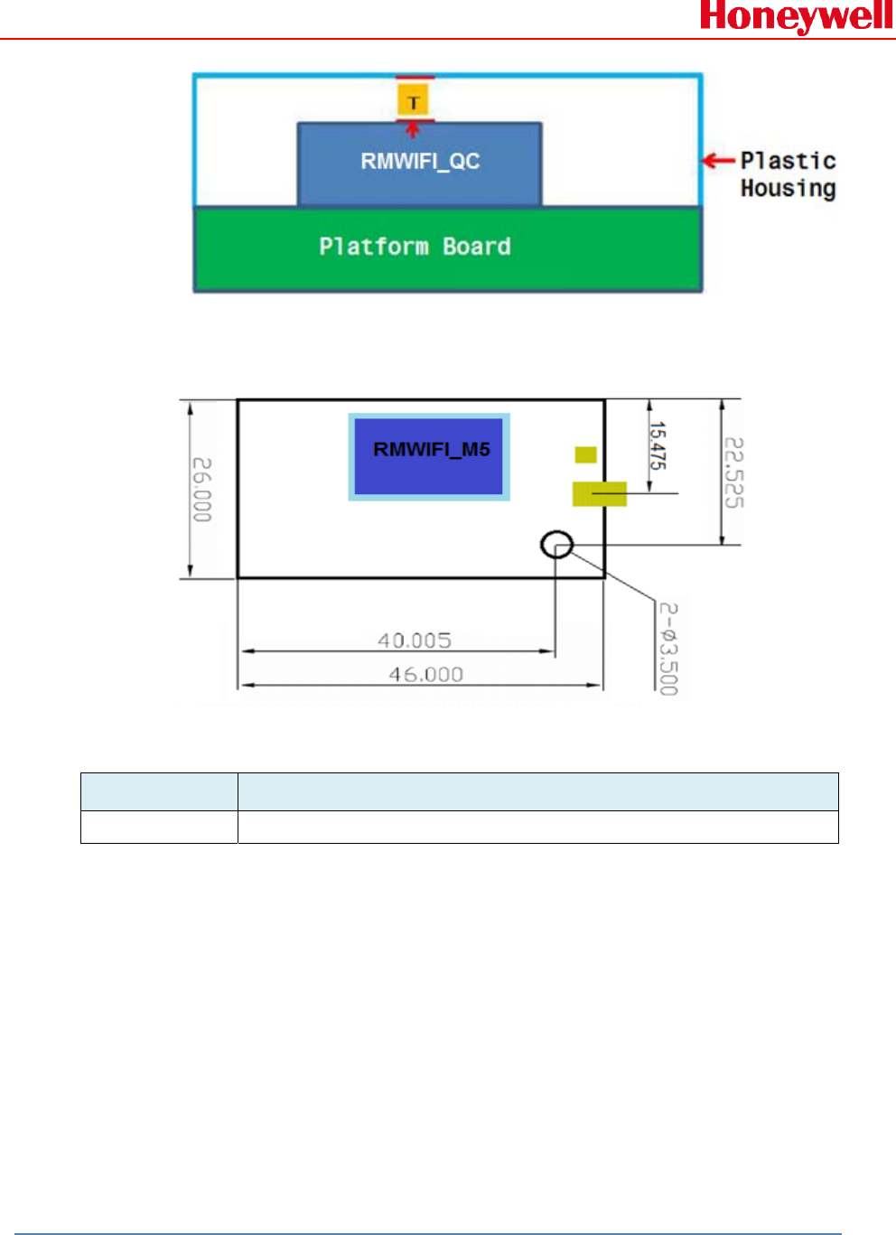
4.3 MountingInformation:
The below diagram shows the PCB layout recommended for RMWIFI-QC
module.
Please minimize components in the keep-out area.
It is recommended to have a 0.4 mm gap (T) between the module's upper surface
and the plastic housing.
Honeywell Confidential and Proprietary Revision –1.1 Page 11 of 15
Copyright © 2015 Honeywell Analytics, All rights reserved.
4.4 MechanicalDrawing:
Unit: mm
4.5 OrderingInformation:
Part Number Description
A01-1106-000 ULTRA LOW-POWER WIRELESS
5. Section5
General declaration for FCC and IC
5.1 FCC&IC(IndustryCanada)
This device complies with Part 15 of the FCC Rules / Industry Canada
license-exempt RSS standard(s). Operation is subject to the following two
conditions:
1. This device may not cause harmful interference, and

Honeywell Confidential and Proprietary Revision –1.1 Page 12 of 15
Copyright © 2015 Honeywell Analytics, All rights reserved.
2. This device must accept any interference received, including
interference that may cause undesired operation.
Le présent appareil est conforme aux CNR d'Industrie Canada applicables
aux appareils radio exempts de licence. L'exploitation est autorisée aux
deux conditions suivantes :
1. L'appareil ne doit pas produire de brouillage, et
2. l'utilisateur del'appareil doit accepter tout brouillage radioélectrique
subi, même si le brouillage est susceptible d'en compromettre le
fonctionnement.
Warning:
Changes or modifications not expressly approved by the party responsible
for compliance could void the user's authority to operate the equipment.
This equipment has been tested and found to comply with the limits for a
Class B digital device, pursuant to part 15 of the FCC Rules. These limits
are designed to provide reasonable protection against harmful
interference in a residential installation. This equipment generates uses
and can radiate radio frequency energy and, if not installed and used in
accordance with the instructions, may cause harmful interference to radio
communications. However, there is no guarantee that interference will not
occur in a particular installation. If this equipment does cause harmful
interference to radio or television reception, which can be determined by
turning the equipment off and on, the user is encouraged to try to correct
the interference by one or more of the following measures:
—Reorient or relocate the receiving antenna.
—Increase the separation between the equipment and receiver.
—Connect the equipment into an outlet on a circuit different from that to
which the receiver is connected.
—Consult the dealer or an experienced radio/TV technician for help.
Under Industry Canada regulations, this radio transmitter may only
operate using an antenna of a type and maximum (or lesser) gain
approved for the transmitter by Industry Canada. To reduce potential radio
interference to other users, the antenna type and its gain should be so
chosen that the equivalent isotropically radiated power (e.i.r.p.) is not
more than that necessary for successful communication.
Conformément à la réglementation d'Industrie Canada, le présent
émetteur radio peutfonctionner avec une antenne d'un type et d'un gain
maximal (ou inférieur) approuvé pour l'émetteur par Industrie Canada.

Honeywell Confidential and Proprietary Revision –1.1 Page 13 of 15
Copyright © 2015 Honeywell Analytics, All rights reserved.
Dans le but de réduire les risques de brouillage radioélectrique à
l'intention des autres utilisateurs, il faut choisir le type d'antenne et son
gain de sorte que la puissance isotrope rayonnée équivalente (p.i.r.e.) ne
dépasse pas l'intensité nécessaire à l'établissement d'une communication
satisfaisante.
5.2 MPE(MaximumRadiatedPower)Requirements
To satisfy FCC / IC RF exposure requirements, a separation distance of
20 cm or more should be maintained between the antenna of this device
and persons during device operation.
To ensure compliance, operations at closer than this distance is not
recommended.
Les antennes installées doivent être situées de facon à ce que la
population ne puisse y être exposée à une distance de moin de 20 cm.
Installer les antennes de facon à ce que le personnel ne puisse approcher
à 20 cm ou moins de la position centrale de l’ antenne.La FCC des éltats-
unis stipule que cet appareil doit être en tout temps éloigné d’au moins 20
cm des personnes pendant son functionnement.
Region Selection
Limited by local law regulations, version for North America does not have
region selection option.
Information for the OEM Integrators
This device is intended for OEM integrators only. Please see the full grant
of equipment document for restrictions.
Label Information to the End User by the OEM or Integrators
If the FCC ID of this module is not visible when it is installed inside
another device, then the outside of the device into which the module is
installed must be label with
“Contains FCC ID: SU3RMWIFI-QC and IC: 20969-RMWIFIQC”.

Honeywell Confidential and Proprietary Revision –1.1 Page 14 of 15
Copyright © 2015 Honeywell Analytics, All rights reserved.
5.3 AntennaRequirements
This radio transmitter (20969-RMWIFIQC) has been approved by Industry
Canada to operate with the antenna types listed below with the maximum
permissible gain and required antenna impedance for each antenna type
indicated. Antenna types not included in this list, having a gain greater
than the maximum gain indicated for that type, are strictly prohibited for
use with this device.
Gain of antenna: 4.9dBi max.
Type of antenna: W1038, Omni-directional
Impedance of antenna: 50ohm
Or
Gain of antenna: 0dBi max.
Type of antenna: PCB Antenna, Monopole
Impedance of antenna: 50ohm
Le présent émetteur radio (20969-RMWIFIQC) a été approuvé par
Industrie Canada pour fonctionner avec les types d'antenne énumérés ci-
dessous et ayant un gain admissible maximal et l'impédance requise pour
chaque type d'antenne. Les types d'antenne non inclus dans cette liste, ou
dont le gain est supérieur au gain maximal indiqué, sont strictement
interdits pour l'exploitation de l'émetteur.
Gain d'antenne: 4.9dBi maximal
Type d'antenne: 50 ohm, W1038, Omni-directionnel
Or
Gain d'antenne: 0dBi maximal
Type d'antenne: 50 ohm, PCB Antenna, Monopole

Honeywell Confidential and Proprietary Revision –1.1 Page 15 of 15
Copyright © 2015 Honeywell Analytics, All rights reserved.
For a composite system that incorporates devices contained either in a
single enclosure or in separate enclosures connected by wire or cable,
testing for compliance with the standards in this part shall be performed
with all of the devices in the system functioning. If an intentional radiator
incorporates more than one antenna or other radiating source and these
radiating sources are designed to emit at the same time, measurements of
conducted and radiated emissions shall be performed with all radiating
sources that are to be employed emitting. A device which incorporates a
carrier current system shall be tested as if the carrier current system were
incorporated in a separate device; that is, the device shall be tested for
compliance with whatever rules would apply to the device were the carrier
current system not incorporated, and the carrier current system shall be
tested for compliance with the rules applicable to carrier current systems.