RDI Technology CA630HR Digital Wireless Camera User Manual USERS MANUAL
RDI Technology (Shenzhen) Co., Ltd. Digital Wireless Camera USERS MANUAL
USERS MANUAL
Page 1
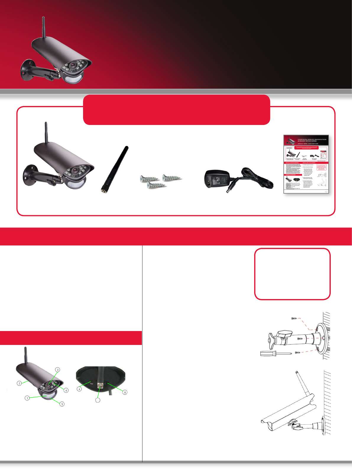
CONTENTS:
Quick Start Guide
Digital Wireless Color
Camera with Stand
Wireless Antenna
for camera
Power Adaptor
for camera*
• Aim the Cameras to best optimize the viewing area:
Select a location for the camera that provides a clear
view of the area you want to monitor, which is free from
dust, and is not in line-of-sight to a strong light source
or direct sunlight.
• Avoid installing the cameras where there are thick
walls, obstructions, or interference (i.e. transformers,
microwave ovens or other electrical equipment)
between the Cameras and the Receiver.
• Select a location for the camera that has an ambient
temperature between 14°F~122°F (-10°C~50°C)
• Before starting permanent installation, have another
person hold the camera for you while you verify its
performance by observing the image on a monitor.
INSTALLING THE CAMERA
Before you install the camera, carefully plan where and how it will be
positioned, and where you will route the cable that connects the
camera to the power adaptor.
INSTALLATION WARNINGS
1. Carefully unpack the Camera.
2. Mount the stand to the wall:
• Mark the position of the
screw holes on the wall.
• Drill holes and insert the
drywall plugs as needed.
• Firmly attach the stand
to the wall using the
provided screws.
3. Attach the Antenna to the
Camera prior to mounting.
4. Place the camera in the
desired mounting position.
Tighten the thumbscrews
to secure the camera to the
Stand. Adjust the angle of
the camera until the
desired view is set.
*May not be exactly as shown
NOTE: AVOID INSTALLING IN A
LOCATION WHICH REQUIRES
THE WIRELESS SIGNAL TO PASS
THROUGH CEMENT, CONCRETE
AND METAL STRUCTURES. THIS
WILL REDUCE THE
TRANSMISSION RANGE.
Mounting
Hardware Kit
COLOR DIGITAL WIRELESS INDOOR/OUTDOOR
ACCESSORY MOTION CAMERA
QUICK START GUIDE
CAMERA OVERVIEW
1. PIR Sensor: Passive IR motion sensor for more accurate
motion recording.
2. Microphone: Built-in microphone underneath camera body.
3. Lens: Camera lens.
4. Night Vision IR: Night vision IR LEDs used for viewing in
complete darkness.
5. Speaker: Speaker for two-way audio.
6. Pair: Pairing button.
7. Antenna: Wireless antenna.
8. Power Cable: Connect the included power adapter to the
cable extending from the camera.
7
Page 2
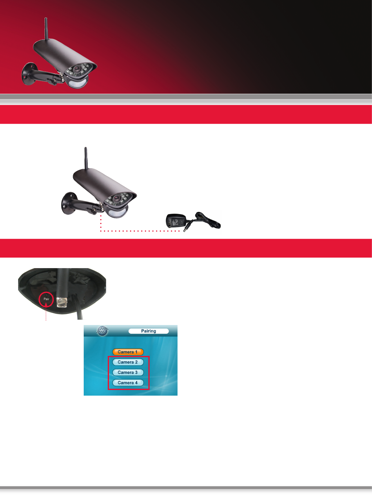
CONNECTING CAMERA POWER ADAPTOR
Connect one end of the camera Power Adaptor to the camera and the other end to an electrical outlet.
1. Press MENU on the wireless receiver or remote control.
2. From the Main Menu, select Pairing and press the
Enter button.
3. Select Camera 2 or Camera 3 or Camera 4 and press
the Enter button.
4. Following the on-screen prompt, press the Pair button
on the rear panel of the camera. You have 30 seconds to
press the PAIR button on the camera. Once paired, the
camera will be immediately displayed on-screen.
NOTE: If you do press the Pair button on the camera during
the 30 second pairing window, repeat steps 1~5 to try the
pairing process again.
Pairing Button
ADDING THE ACCESSORY CAMERA TO YOUR SYSTEM
The Pairing Function assigns each camera to a different
channel on the wireless receiver (connect up to 4
Cameras), and is necessary for configuring additional
cameras. By default the camera that came with the sys-
tem is assigned to channel no. 1
NOTE: It is highly recommended to pair the Accessory
Camera to the Receiver before permanently mounting the
camera. For detailed information, please check the own-
ers manual for the system.
Connect power adaptor to
local power outlet
COLOR DIGITAL WIRELESS INDOOR/OUTDOOR
ACCESSORY MOTION CAMERA
QUICK START GUIDE
FCC NOTE:
This device complies with Part 15 of the FCC Rules.
Operation is subject to the following two conditions: (1) this device may not cause
harmful interference, and (2) this device must accept any interference
received, including interference that may cause undesired operation.
THE MANUFACTURER IS NOT RESPONSIBLE FOR ANY RADIO OR TV
INTERFERENCE CAUSED BY UNAUTHORIZED MODIFICATIONS OR
CHANGE TO THIS EQUIPMENT. SUCH MODIFICATIONS OR CHANGE
COULD VOID THE USER’S AUTHORITY TO OPERATE THE EQUIPMENT.
To maintain compliance with FCC’s RF exposure guidelines, this equipment
should be installed and operated with a minimum distance of 20cm between the
radiator and your body.