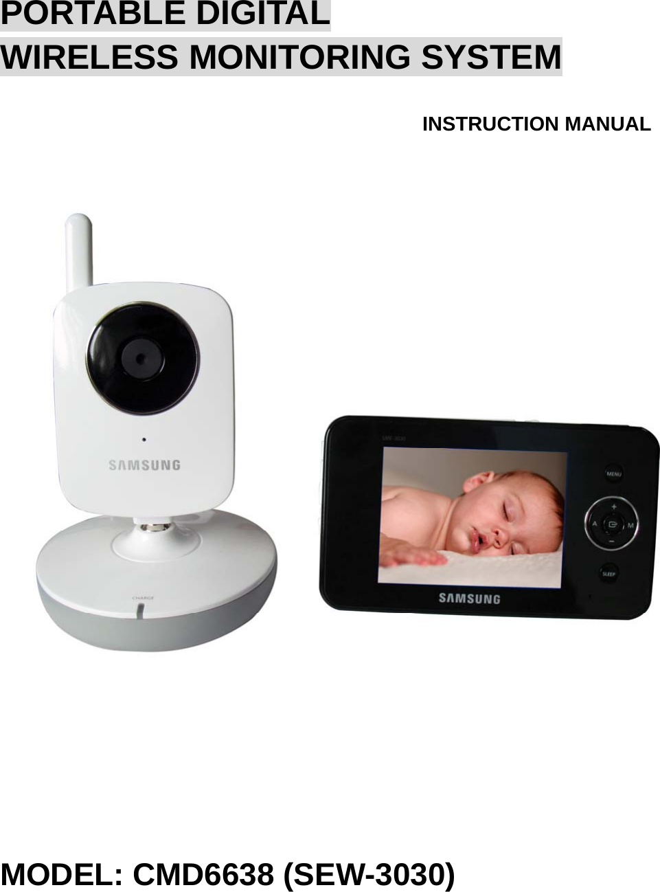
RDI Technology SEB-1014R Digital Camera and Monitor System User Manual SEW 3030
RDI Technology (Shenzhen) Co., Ltd. Digital Camera and Monitor System SEW 3030
UserManual.wiki
>
RDI Technology
>
SEB 1014R User Manual
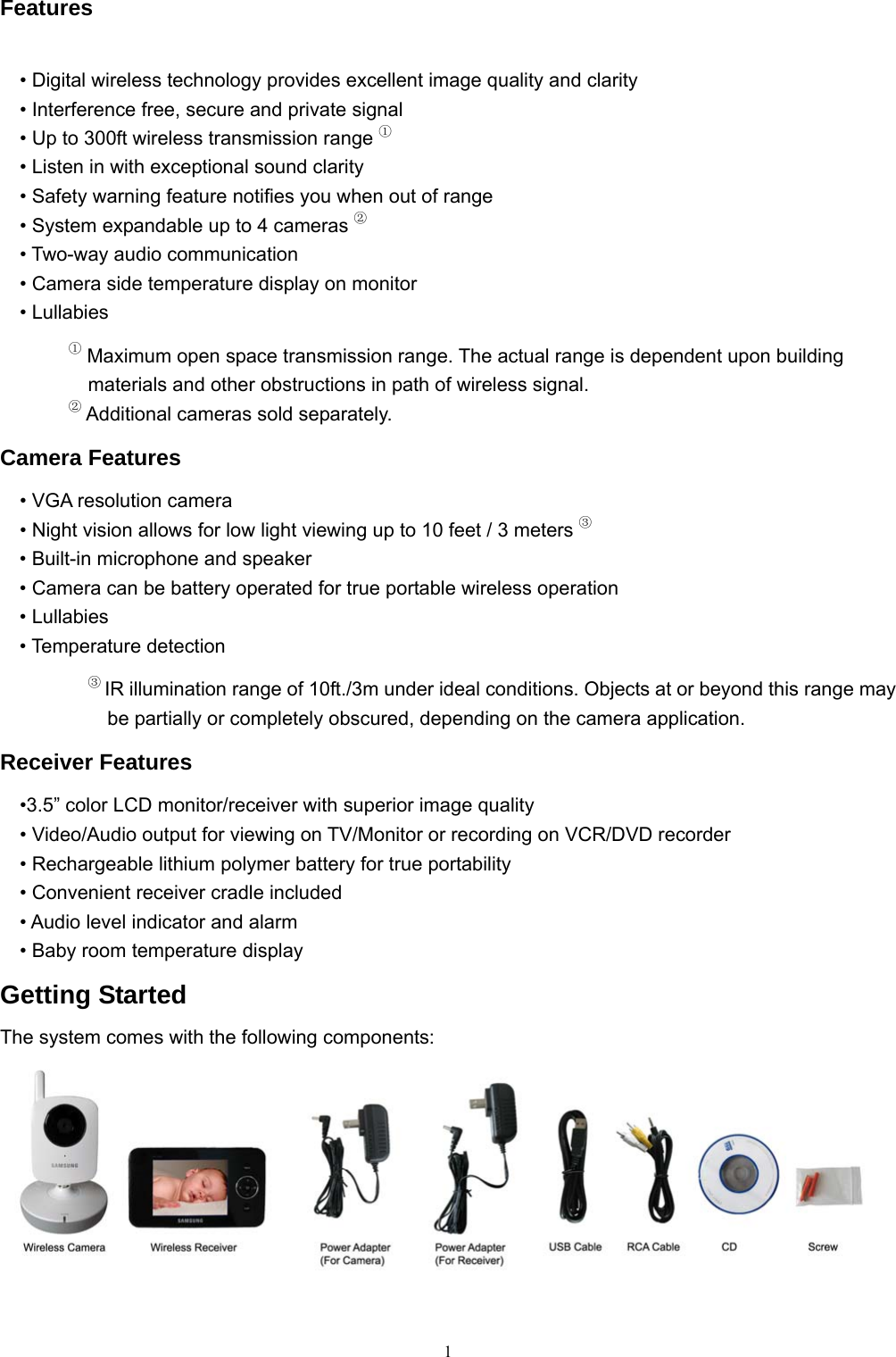
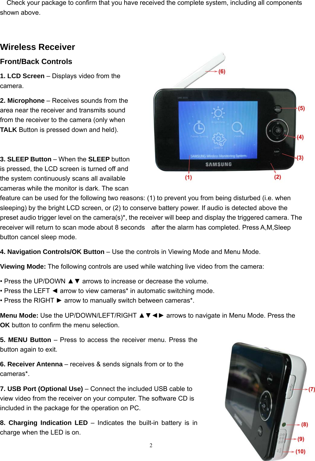
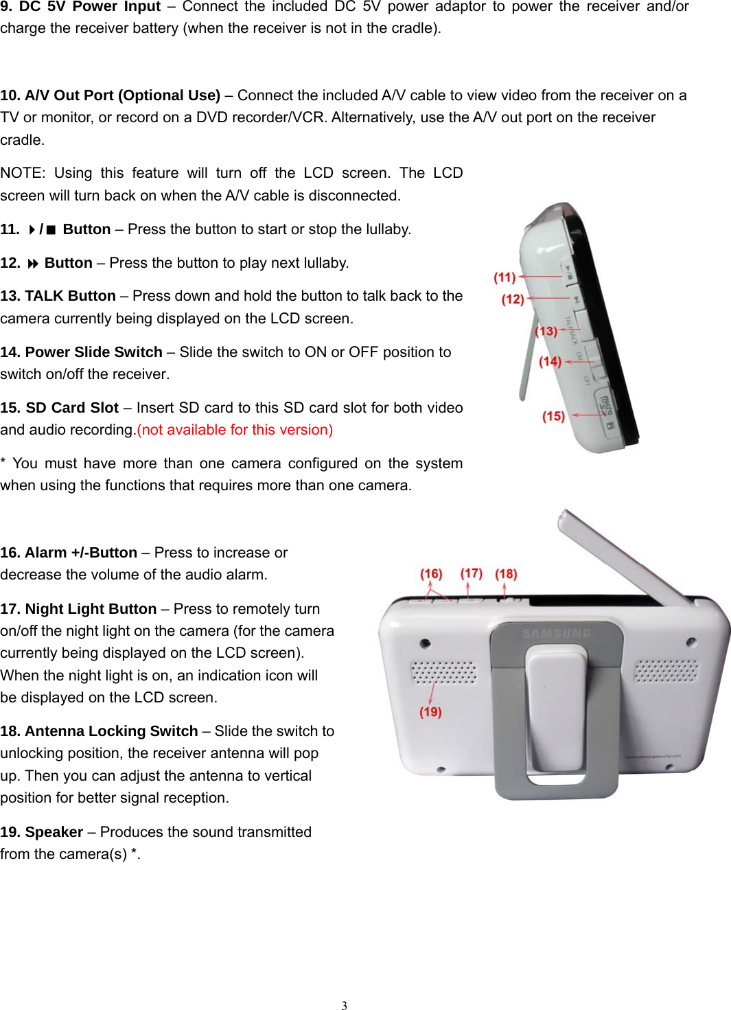
Users Manual
Navigation menu
Upload a User Manual
Namespaces
Wiki Guide
HTML
PDF
Info
Views
User Manual
Discussion / Help
Navigation