RDI Technology SEB-1014R Digital Camera and Monitor System User Manual SEW 3030
RDI Technology (Shenzhen) Co., Ltd. Digital Camera and Monitor System SEW 3030
Users Manual
PORTABLE DIGITAL
WIRELESS MONITORING SYSTEM
INSTRUCTION MANUAL
MODEL: CMD6638 (SEW-3030)
1
Features
• Digital wireless technology provides excellent image quality and clarity
• Interference free, secure and private signal
• Up to 300ft wireless transmission range ①
• Listen in with exceptional sound clarity
• Safety warning feature notifies you when out of range
• System expandable up to 4 cameras ②
• Two-way audio communication
• Camera side temperature display on monitor
• Lullabies
① Maximum open space transmission range. The actual range is dependent upon building
materials and other obstructions in path of wireless signal.
② Additional cameras sold separately.
Camera Features
• VGA resolution camera
• Night vision allows for low light viewing up to 10 feet / 3 meters ③
• Built-in microphone and speaker
• Camera can be battery operated for true portable wireless operation
• Lullabies
• Temperature detection
③ IR illumination range of 10ft./3m under ideal conditions. Objects at or beyond this range may
be partially or completely obscured, depending on the camera application.
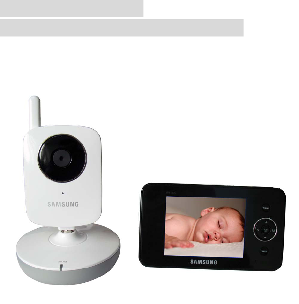
Receiver Features
•3.5” color LCD monitor/receiver with superior image quality
• Video/Audio output for viewing on TV/Monitor or recording on VCR/DVD recorder
• Rechargeable lithium polymer battery for true portability
• Convenient receiver cradle included
• Audio level indicator and alarm
• Baby room temperature display
Getting Started
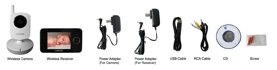
The system comes with the following components:
2
Check your package to confirm that you have received the complete system, including all components
shown above.
Wireless Receiver
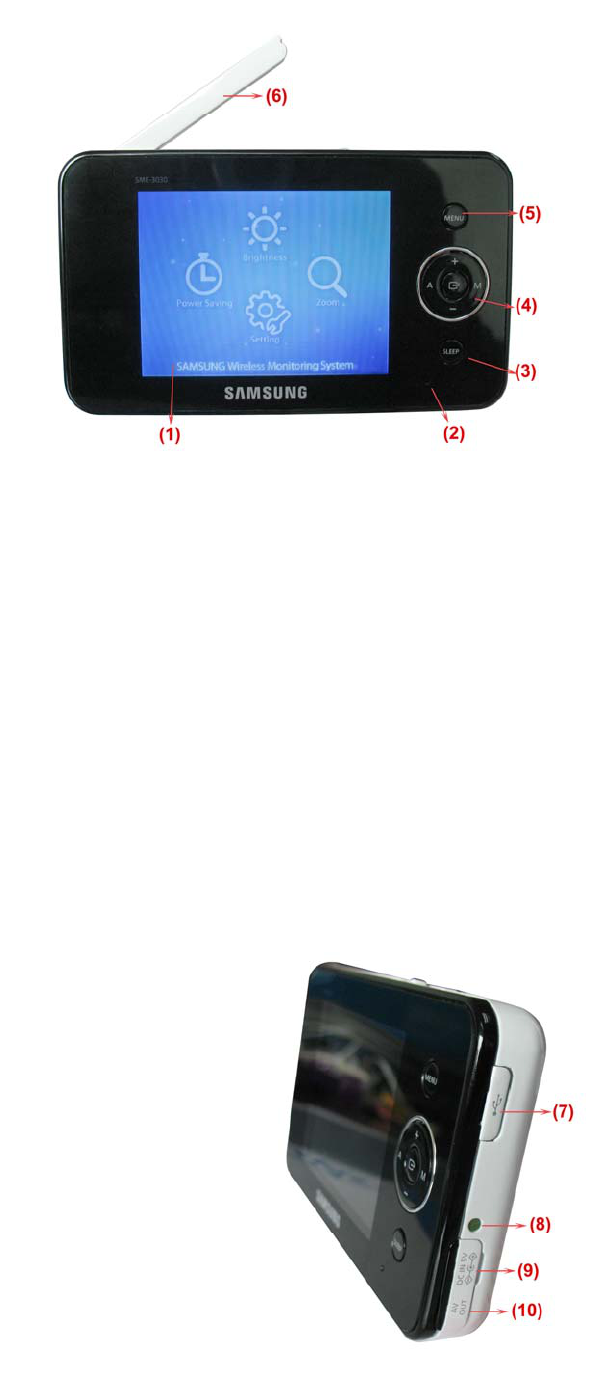
Front/Back Controls
1. LCD Screen – Displays video from the
camera.
2. Microphone – Receives sounds from the
area near the receiver and transmits sound
from the receiver to the camera (only when
TALK Button is pressed down and held).
3. SLEEP Button – When the SLEEP button
is pressed, the LCD screen is turned off and
the system continuously scans all available
cameras while the monitor is dark. The scan
feature can be used for the following two reasons: (1) to prevent you from being disturbed (i.e. when
sleeping) by the bright LCD screen, or (2) to conserve battery power. If audio is detected above the
preset audio trigger level on the camera(s)*, the receiver will beep and display the triggered camera. The
receiver will return to scan mode about 8 seconds after the alarm has completed. Press A,M,Sleep
button cancel sleep mode.
4. Navigation Controls/OK Button – Use the controls in Viewing Mode and Menu Mode.
Viewing Mode: The following controls are used while watching live video from the camera:
• Press the UP/DOWN ▲▼ arrows to increase or decrease the volume.
• Press the LEFT ◄ arrow to view cameras* in automatic switching mode.
• Press the RIGHT ► arrow to manually switch between cameras*.
Menu Mode: Use the UP/DOWN/LEFT/RIGHT ▲▼◄► arrows to navigate in Menu Mode. Press the
OK button to confirm the menu selection.
5. MENU Button – Press to access the receiver menu. Press the
button again to exit.
6. Receiver Antenna – receives & sends signals from or to the
cameras*.
7. USB Port (Optional Use) – Connect the included USB cable to
view video from the receiver on your computer. The software CD is
included in the package for the operation on PC.
8. Charging Indication LED – Indicates the built-in battery is in
charge when the LED is on.
3
9. DC 5V Power Input – Connect the included DC 5V power adaptor to power the receiver and/or
charge the receiver battery (when the receiver is not in the cradle).
10. A/V Out Port (Optional Use) – Connect the included A/V cable to view video from the receiver on a
TV or monitor, or record on a DVD recorder/VCR. Alternatively, use the A/V out port on the receiver
cradle.
NOTE: Using this feature will turn off the LCD screen. The LCD
screen will turn back on when the A/V cable is disconnected.
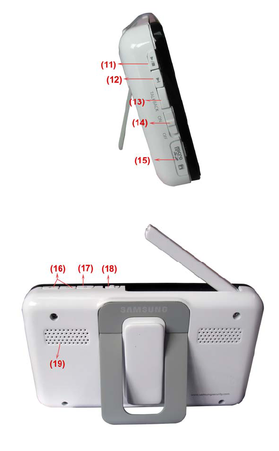
11. / Button – Press the button to start or stop the lullaby.
12. Button – Press the button to play next lullaby.
13. TALK Button – Press down and hold the button to talk back to the
camera currently being displayed on the LCD screen.
14. Power Slide Switch – Slide the switch to ON or OFF position to
switch on/off the receiver.
15. SD Card Slot – Insert SD card to this SD card slot for both video
and audio recording.(not available for this version)
* You must have more than one camera configured on the system
when using the functions that requires more than one camera.
16. Alarm +/-Button – Press to increase or
decrease the volume of the audio alarm.
17. Night Light Button – Press to remotely turn
on/off the night light on the camera (for the camera
currently being displayed on the LCD screen).
When the night light is on, an indication icon will
be displayed on the LCD screen.
18. Antenna Locking Switch – Slide the switch to
unlocking position, the receiver antenna will pop
up. Then you can adjust the antenna to vertical
position for better signal reception.
19. Speaker – Produces the sound transmitted
from the camera(s) *.
4
Wireless Receiver Installation
Determine if you will be using the receiver cradle, or connecting the cables directly to the receiver before
installation:
1. Place the receiver cradle or receiver in a place that will have clear reception with your camera(s).
2. Plug the AC adaptor power output cable into the 5V POWER input of the cradle or receiver. Plug the
power plug into a wall outlet or surge protector.
3. Leave the receiver to charge for several hours prior to first time use so the built-in rechargeable
receiver battery is fully charged. DO NOT remove the power cable from the receiver / from the cradle
during initial charge process. After initial charge, charge the receiver as required.
4. If you wish to view the receiver images on a larger screen, connect the included AV cable to the cradle
or receiver, and connect the other end of the cable to the Video IN (Yellow) and Audio IN (White) ports on
the TV, VCR or other viewing/recording device.
If you wish to view the receiver images on the computer, connect one end of the included USB cable to
the receiver, and connect the other end of the cable to the USB port on the computer. (Need to install
driver in the disc first).
NOTE: the purpose of the AV output is for convenience only. When using with large screen TV/Monitor,
the picture might be grainy as the camera limits video resolution to VGA (640x480 pixels). This is not a
product defect. For best performance use with TV/Monitor PIP (Picture in Picture) function.
Check your TV/Monitor product manual to see if this feature is available on your TV/Monitor. This allows
you to view TV or other video source and see video from the camera in a small window on the same
screen.
Wireless Camera
Front & Back Controls
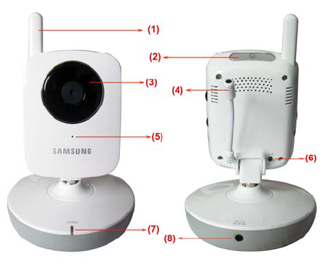
1. Camera Antenna – Sends & receives signals to or from the receiver.
2. Night Light Switch – Press to turn the night light ON or
OFF. Alternatively, press the light button on the receiver to
remotely turn the camera light ON or OFF.
Note: Night Light is available only when the camera is paired
to the receiver.
3. Lens/IR LED Cover – Infrared LEDs provide viewing in
no/low light conditions
4.Temperature Sensor--- Use to make a temperature
induction in the camera side
5. Microphone – Receives sounds for the area near the
camera, and transmits sound from the camera to the
receiver.
6. Pair Button – The pair button is located on the back of the camera behind the stand mount.
5
7. Charging Indication LED – Indicates the camera is in charge when the LED is red on
8. DC 5V Power – Connect the DC 5V power adaptor to the camera
NOTE: The camera can also be powered using 3 AA batteries (not included) installed in the base. If the
camera is plugged in with the AC adaptor, the batteries will not be used. The batteries are intended for
short term, portable camera use.
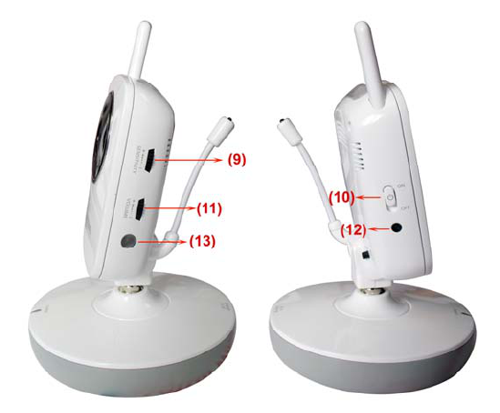
Side Controls
9. Sound Alarm Trigger – Adjust the sensitivity knob to set the sound alarm sensitivity. The receiver will
beep to alert you when the sound is above a preset sound level. Adjust the sensitivity knob to increase or
decrease the level.
10. Camera ON/OFF Switch – Turns the camera ON or OFF.
11. Volume—Press to increase or decrease the volume of the audio alarm.
12.Camera ON and low battery indication—Turn on the camera, the LED light show green ; Low
battery,the LED light is blinking.
13.Night vision sensor—Use to detect the illumination in the camera side.
Camera Installation
Before you install the camera, carefully plan where and how it will be positioned, and where you will
route the cable that connects the camera to the power adaptor.
Before starting permanent installation, verify its performance by observing the image on the receiver
when camera is positioned in the same location/position where it will be permanently installed and the
receiver is placed in the location where it will be used most of the time.
Installation Warnings
Aim the camera(s) to best optimize the viewing area: Select a location for the camera that provides a
clear view of the area you want to monitor, which is free from dust, and is not in line-of-sight to a strong
light source or direct sunlight.
6
Avoid installing the cameras where there are thick walls, or obstructions between the Cameras and the
Receiver.
Night Vision
This camera has built-in IR LEDs, which provides the camera with the ability to view images in no/low
light conditions. It is important to use the provided power adaptor (and not the batteries) when using the
camera for prolonged periods in low light conditions, as the built-in IR LEDs will drain the battery more
quickly than regular daytime use.
Installing the Camera
1. Carefully unpack the camera.
NOTE: If you are installing cameras that did not come with the
system, please see the pairing camera section of this manual for
details on installation.
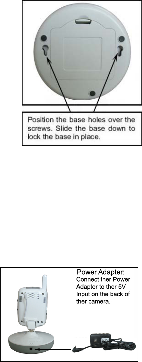
2. Mount the camera to the wall.
Mark the position of the screw holes on the wall, and drill holes
and insert 2 screws, then firmly attach the camera to the wall by
placing the stand over the installed screws and pushing the
base downwards.
NOTE: The camera can also be placed on a flat surface, such
as a Table or Shelf, and no mounting hardware is required.
3. Adjust the viewing angle of the camera
NOTE: You can install additional cameras (maximum of 4
cameras). When adding cameras that were not included in the original box, you will need to pair up the
cameras with the receiver. Refer to the camera pairing section of this manual.
Connecting Camera Power
The camera can be powered either by using the provided power adaptor, or using batteries (requires 3
AA type batteries, not included).
NOTE: Wireless cameras require a power source (either an electrical outlet or battery power) to operate.
If you plan to permanently mount the camera in a location, it is recommended to use the included
camera power adaptor to prevent interruptions in the image, as using battery power is intended as a
temporary power solution.
Power Adaptor
Connect the power adaptor to the camera. Make sure
the power adaptor is placed into a grounded outlet or
surge bar to protect the camera from power fluctuations.
7
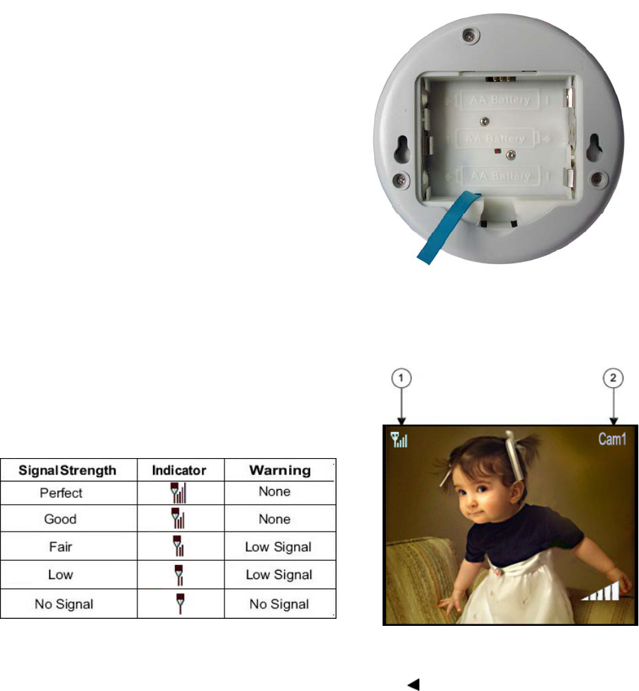
Battery Pack
1. Remove the battery cover off the base of the camera.
2. Insert 3 AA batteries (not included) into the Battery
Pack. Make sure to correctly line up the Positive (+) and
negative (-) terminals of the batteries.
3. Place the battery pack cover back on.
NOTE: If the camera is plugged in with the AC adaptor,
the batteries will not be used. The batteries are intended
for short term, portable camera use only.
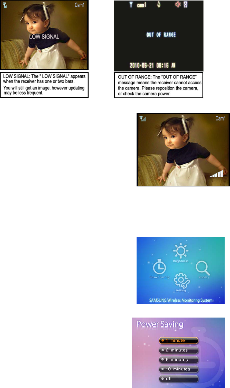
Viewing Mode
1. Signal Indicator – The signal indicator shows the strength of the signal being received from the
camera. The number of bars in the signal indicator shows the strength of the signal – One or No Bars
indicates the signal is poor, and 4 bars indicate a very strong
signal.
Signal Indicators:
2. Channel Indicator – Displays the current channel
number. Press the RIGHT ► arrow on the receiver to switch between available cameras.
Note: To automatically switch between channels, press the LEFT arrow (AUTO).
Low Signal / No Signal Warnings
When the camera is positioned too far from the receiver, warning messages will be displayed.
8
Adjusting the Receiver Volume
The receiver volume can be adjusted by using the
UP/DOWN▲▼ arrows when viewing a camera.
Press the DOWN▼ arrow to decrease the volume, and press
the UP▲ arrow to increase the volume. When the volume is set
to one bar (lowest setting), the volume is muted.
The volume adjustment icon will be displayed during volume
changes, and will disappear after 10 seconds of inactivity.
Accessing Menu System
Press the MENU button on the receiver to enter menu system. Use the navigating buttons to navigate
up/down/left/right in the menu, and press the OK button to confirm a setting.
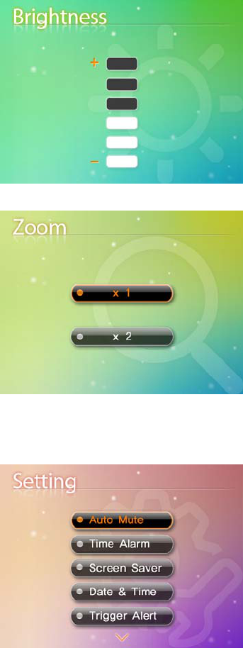
Main Menu
The Main Menu contains 4 submenus:
1.POWER SAVING – Turns on the receiver power save mode
(when no activity on the cameras is detected).
2. Brightness– Adjusts the brightness of the image
3.Zoom –Achieve large image on this function.
4. SETTING – In this submenu you can set auto mute, time
alarm, select screen saver pictures, image times, trigger alert,
temperature unit, temperature alert parameters, choose the
TV system for A/V output, reset the receiver to factory defaults (erases all configurations) and pair
between camera and monitor channel.
Power Saving Menu
The Power Saving Menu is used to turn off the screen at a
9
predetermined time, to save battery. This function can be set to 1 minute, 2 minutes, 5 minutes, 10
minutes, or disabled by selecting off.
The monitor will go to black screen to save battery after the time you have set (1minute, 2 minutes, 5
minutes or 10 minutes).
It will be activated by pushing any button on the front panel of monitor or by higher sound detected by
cameras.
If it is activated by pushing any button (except OK button) on front panel of monitor, the monitor will go
back to black screen after the time you set if there is no sound trigger during that time.
If it is activated by higher sound (sound trigger), it will go back to black screen about 8 seconds after the
last trigger.
Brightness
The Brightness menu is used to adjust the brightness of the
image.
Use the UP and DOWN arrows to change the bar from
DARKEST (bottom) to LIGHTEST (top). Press the OK button
to confirm the change.
Zoom
The image can be set at original size or double size by
selecting zoom x1 and zoom x 2. In double size mode, press
the navigation buttons to view the parts out of the LCD screen.
Settings
The Setting Menu contains 10 submenus:
1). Auto Mute – Auto mute function is to automatically cut off
the audio when there is only slight environmental noise on
camera side. In the submenu you can switch on/off this
function.
2).Time Alarm-Sets the time to awake you as alarm clock
3). Screen Saver – 5 pictures are stored in the system. You
can select one picture to make it be shown on the LCD screen
in scan mode. Or you can select Blank screen to make the
LCD screen display nothing in scan mode.
4)Date& Time-sets the time value to show in the monitor screen
5)Trigger Alert- Select the alert manner while something be detected.
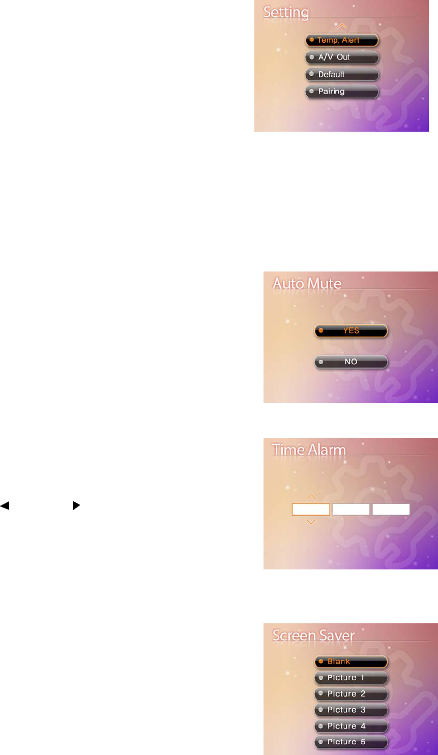
10
6)Temperature Unit—Choose the ℃ or ℉ for temperature
unit
7). Temperature Alert – Sets the temperature alert range.
Once the temperature on camera side is out of the range, the
monitor will beep to alert you.
8). A/V Out – Chooses the TV system for A/V output.
9).Factory Reset– Choose Yes to reset the receiver to factory
defaults. All menu settings will be reset.
NOTE: Resetting the receiver will not reset all camera pairing.
10) Pairing– Use the pairing menu to add camera(s) to the receiver.
Auto mute
This function is to automatically cut off the audio when there is
only slight environmental noise on camera side. Choose Yes to
enable this function.
When auto mute function is enabled, the monitor audio will be
cut off after 5 minutes when there is only slight environmental
noise on camera side. seconds
In auto mute mode, the audio can be activated by real noise or
higher sound detected on camera side. After last activation, the
monitor audio will go back to off status when there is no sound
trigger within 5 minutes.
Time Alarm
You can set the time value with HH,MM and select the ON or
OFF to decide alarm or not.
Use LEFT and RIGHT arrows to select HH,MM ,then use
the UP and DOWN ▼▲ arrows to set the time value. After
successfully setting the time value , choose ON and then press
the OK button to confirm the setting.
Selected ON, it can awake on the preset time. While choose
OFF, the function will be shut down.
Screen Saver
5 pictures are stored in the system. You can select one picture
to make it be shown on the LCD screen in scan mode. Or you
11
can select Blank screen to make the LCD screen display nothing in scan mode.
Date & Time
You can set the time value with YY MM DD HH MM to show in
the monitor screen.
Trigger Alert
You can select the Vibration or Beep as the trigger alert manner
while something has been detected by camera side
Temperature Unit
The ℃ or ℉unit has exist to been selected to show the
temperature in the monitor screen
Temperature Alert
The menu is to set the temperature range of audio alert. When
the temperature on the camera side is out of the range, the
monitor will beep to alert you.

12
Use LEFT and RIGHT arrows to select low temperature or high temperature, then use the UP and
DOWN ▼▲ arrows to set the temperature value. After successfully setting the temperature range,
choose ON and then press the OK button to confirm the setting.
Choose OFF to disable temperature alert function.
A/V Out
The menu is to choose the TV system and resolution when
outputting the video/audio to TV, DVR/VCR or other
viewing/recording devices.
Factory Reset
Choose Yes to reset the receiver to factory defaults – all menu
settings will be reset.
NOTE: Camera pairing settings will NOT be affected by a reset.
Cameras will remain paired with the receiver.
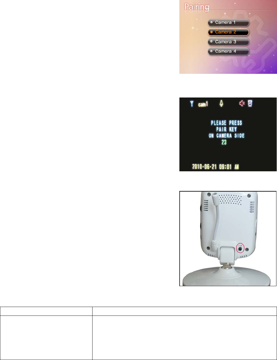
Pairing
The system comes with camera(s) that have already been
paired. The pairing function assigns each camera to a different
channel on the wireless receiver (up to 4 Cameras), and it is
necessary for configuring additional cameras.
Use the UP▼ and DOWN▲ arrows to select the desired pairing
channel, and press the OK button to begin the pairing process
with a camera.
NOTE: It is highly recommended to pair the cameras to the
receiver before permanently mounting the cameras. See the pairing section on this manual for details.
Camera Pairing
The system comes with camera(s) that have already been paired. These cameras will communicate with
the receiver once powered on.
The pairing function assigns each camera to a different channel
on the wireless receiver (up to 4 cameras), and is necessary for
configuring additional cameras.
NOTE: It is highly recommended to pair the cameras to the
receiver before permanently mounting the cameras.
13
1. Power on the camera by connecting the power adaptor or battery pack, and turning the switch to ON.
The power LED for the camera should be ON.
2. Power on the receiver by connecting the power adaptor to the 5V Input on the side.
3. Press the MENU button on the receiver. Navigate to the Pairing
menu option by pressing the ▼▲ keys to navigate. Press the OK
button to open the Pairing menu.
4. Select a channel by pressing the UP and DOWN ▼▲ arrows.
Press the OK button on the receiver to accept.
5. A message will be displayed on the receiver screen.
The receiver will count down from 30~0 – you must press the Pair
button on the camera during this time to successfully pair the
camera.
If the button on the camera is not pressed, the receiver will return
to the view screen, and no pairing will take place.
6. Press the Pair button on the back of the camera.
Once the camera has been paired, it will be immediately viewable
on the receiver monitor.
Troubleshooting
If you have problems with the system, there is often a quick and simple solution. Please try the following:
Problem Solution
No picture from a camera
1. Check all connections to the camera. Make sure the adaptor is
plugged in.
2. Make sure that the cameras and receiver are both ON.
3. Make sure that the camera is in range of the receiver.
4. If using the battery adaptor, try replacing the batteries

14
The picture is dropping
1. Move the camera closer to the receiver.
2. Try repositioning the camera, receiver or both to improve the
reception.
3. Adjust the monitor antenna to vertical position.
Audio problems
1. Ensure that the volume on the TV is on.
2. Make sure that there is sound within range of the camera
microphone
3. If the unit emits a loud screeching noise (feedback), move the
camera or receiver farther apart.
The picture is or has become
choppy
The picture may become choppy when experiencing a lower frame
rate (i.e. 10 frames per second vs. a higher 20 frames per second).
1. Try moving the camera closer to the receiver.
2. Remove obstructions between the receiver and camera.
3. Adjust the monitor antenna to vertical position.
The Picture appears to be grainy
when using AV out function to
view on a large screen TV/Monitor
The purpose of the AV output is for convenience only. When using
with large screen TV/Monitor, the picture might be grainy as the
camera limits video resolution to VGA (640x480 pixels). This is not a
product defect.
1. For best performance use with TV/Monitor PIP (Picture in Picture)
function. Check your TV/Monitor product manual to see if this feature
is available on your TV/Monitor
2. View video on a smaller screen TV/Monitor
Appendix #1 - Receiver Specifications
Receiver
Receiving Frequency Range 2.400GHz~2.483.5GHz
Data Rate 2 Mbps
Receiving Sensitivity -81dBm
Demodulation Type GFSK with FHSS
Resolution 320 (RGB) x 240
Viewing Angle H: 120° V: 100°
A/V Output / Resolution VGA 640x480 / 10FPS, QVGA 320x240 / 25FPS
Power Requirement 5V DC ±5%
Power Consumption 400mA Max without charging
800mA with charging
Operating Temp Range 14°F ~ 104°F (-10° ~ 40° C)
Operating Humidity 0 ~ 85% RH
Appendix #2 - Camera Specifications

15
Camera(s)
Transmit Frequency Range 2.400GHz~2.483.5GHz
Data Rate 2 Mbps
Transmitting Power 14dBm (TYP)
Modulation Type GFSK with FHSS
Transmitting Distance 100m (Line of Sight)
Image Sensor Type 1/4” Color CMOS Image Sensor
Effective Pixels H: 640 V: 480
Image Processing Motion JPEG
Image Resolution / Frame Rate H: 640 V: 480 / 30FPS Max
White Balance Auto
Lens 4.9mm / F2.8
Viewing Angle (Diagonal) 50°
Minimum Illumination 0 LUX (IR On)
IR LED / Night Vision Range 8 LEDs / 940nm 3m (with IR LED)
Power Requirement 5V DC ±5%
Power Consumption
360mA MAX (with Night Light)
300mA (without Night Light)
Operating Temperature 14°F ~ 104°F (-10°C ~ 40°C)
Operating Humidity 0% ~ 85%
Environment Rating 14°F ~ 144°F (-10° ~ 60° C)
This device complies with Part 15 of the FCC Rules.
Operation is subject to the following two conditions: (1) this device may not cause harmful
interference, and (2) this device must accept any interference received, including interference that
may cause undesired operation.
FCC NOTE:
THE MANUFACTURER IS NOT RESPONSIBLE FOR ANY RADIO OR TV INTERFERENCE CAUSED BY
UNAUTHORIZED MODIFICATIONS TO THIS EQUIPMENT. SUCH MODIFICATIONS COULD VOID THE
USER'S AUTHORITY TO OPERATE THE EQUIPMENT.
To maintain compliance with FCC’s RF exposure guidelines, this equipment should be installed and
operated with minimum distance 20cm between the radiator and your body. Use only the supplied
antenna.
This statement makes the operation at greater than 20cm clear.So not requires SAR Testing.