REEBOK Treadmill Manual L0704426
User Manual: REEBOK REEBOK Treadmill Manual REEBOK Treadmill Owner's Manual, REEBOK Treadmill installation guides
Open the PDF directly: View PDF ![]() .
.
Page Count: 30
ModelNo.RBTL13305.0
SedaJNo.
WritetheseriaUnumberinthespace
aboveforfuturereference.
Asa manufacturer,wearecorn-
rnittedto providingcomplete
customersatisfaction,if you
havequestions,orif partsare
damagedormissing, PLEASE
CONTACT OUR CUSTOMER
SERVICE DEPARTMENT
DIRECTLY.
CALL TOLL-FREE:
1-877-994-4999
Mon.=Fri., 6 a.rn.=6 p.m. NST
ON THE WEB:
www.reebokservice.corn
CAUTmON
Read aJl precautions and instruc-
tions in this manual before using
this equipment. Save this rnano
ual for future reference.
'S
www.reebokhomefitness.com
new products, prizes,
fitness tips, and much more!
TABLE OF CONTENTS
iMPORTANT PRECAUTIONS ................................................................. 3
BEFORE YOU BEGIN ....................................................................... 6
ASSEMBLY ............................................................................... 7
TREADMILL OPERATION ................................................................... 10
HOW TO FOLD AND MOVE THE TREADMILL .................................................. 22
TROUBLESHOOTING ...................................................................... 23
EXERCISE GUiDELiNES ................................................................... 25
PART LIST ............................................................................... 26
HOW TO ORDER REPLACEMENT PARTS ..................................................... 27
LiMiTED WARRANTY ............................................................... Back Cover
Note: An EXPLODED DRAWING is attached in the center of this manual,
REEBOK and the Vector Logo _--_L_are registered trademarks and service marks of Reebok, This product is
manufactured and distributed under license from Reebok International,
2
iMPORTANT PRECAUTIONS
WAR NING: Toreducether s.ofburns,f re,electdcshock,orinjurytopersons,readthe
following important precautions and information before operating the treadmill.
1. it is the responsibility of the owner to ensure 11. Failure to use a properly functioning surge
that all users of this treadmill are adequateJy suppressor could result in damage to the con=
informed of all warnings and precautions= trol system of the treadmill, if the control sys-
tem is damaged, the walking belt may change
2. Use the treadmill onJy as described in this speed, accelerate, or stop unexpectedly,
manual which may resuJt in a fuji and serious injury.
3=
4. Keep the treadmill indoors, away from mois-
ture and dust. Do not put the treadmill in a
garage or covered patio, or near water.
Place the treadmill on a levemsurface, with at 12. Keep the power cord and the surge suppres-
least eight feet of clearance behind it and two sot away from heated surfaces.
feet on each side. Do not place the treadmill
on any surface that blocks air openings. To 13. Never move the walking beff whiJe the power
protect the fJoor or carpet from damage, place is turned off. Do not operate the treadmill if
amat under the treadmill the power cord or plug is damaged, or if the
treadmill is not working properly. (Bee
BEFORE YOU BEGIN on page 6 if the tread-
mill is not working properly.)
5. Do not operate the treadmill where aerosoJ
products are used or oxygen is administered.
14. Read, understand, and test the emergency
stop procedure before using the treadmill (see
TREADMILL OPERATION on page 10).
6. Keep children under the age of 12 and pets 15. Never start the treadmill while you are stand-
away from the treadmill at aH times, ing on the walking beff. Always hold the
handrails while using the treadmill.
7. The treadmill should not be used by persons
weighing more than 350 pounds. Never allow 16. To protect the treadmill and TV during Hght-
more than one person on the treadmill at a time. ning storms, unplug the power cord from the
8. Wear appropriate exercise clothes when
using the treadmill. Do not wear loose clothes
that could become caught in the treadmiJL
AtHetic support cJothes are recommended
for both men and women. Always wear ath-
letisshoes. Never use the treadmillwithbare
feet,wearing only stockings,or in sandals.
9. When connectin£ the power cord (see page 10),
plug the power cord into a surge suppressor
{not included) and pJug the surge suppressor
into a grounded circuit capable of carrying 15
walJ outlet and disconnect the antenna or
cable system. This will prevent damage due
to lightning and power line surges.
17. The treadmill is capable of high speeds.
Adjust the speed in small increments to avoid
sudden jumps inspeed.
18. The pulse sensor is not a medical device.
Various factors, including the user's move-
ment, may affect the accuracy of heart rate
readings. The pulse sensor is intended only
as an exercuse aid in determining heart rate
or more amps. No other appliance should be on trends in general
the same circuit. Do not use an extension cord.
19. Never leave the treadmill unattended while it
10. Use only a singJe-outlet surge suppressor that is running. Always remove the key, unplug
meets aH of the specifications described on the power cord, and move the reset/off circuit
page 10. To purchase a surge suppressor, see breaker to the "off" position when the tread-
your iocat REEBOK denier or calJ the tolFfree mill is not in use. (See the drawing on page 6
telephone number on the front cover of this for the location of the circuit breaker.)
manual and order part number 146148, or see
your tocaJ electronics store.
20. Do not attempt to raise, lower, or move the
treadmiJJ untiJ it is propedy assembled. (See
ASSErvIBLY on page 7, and HOW TO FOLD
AND MOVE THE TREADMILL on page 22.)
You must be able to safely lift 45 pounds _20
kg) to raise, lower, or move the treadmi&
21. When folding or moving the treadmi& make
sure that the storage latch is fully dosed.
22. mnspect and properly tighten all parts of the
treadmill every three months.
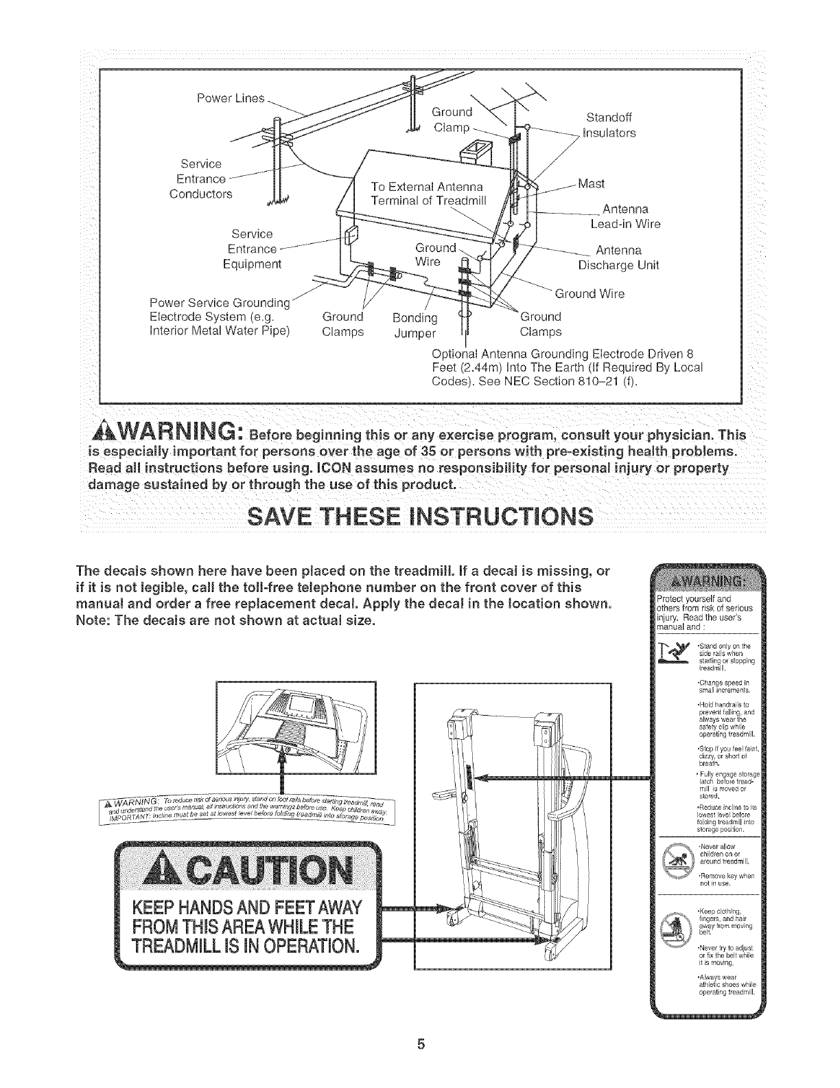
27. An outside antenna system should not be lo-
cated in the vicinity of overhead power lines
or other eieetdc light or power circuits, or
where it can fall into such power lines or cir°
cuits. When installing an outside antenna
system, extreme care should be taken to keep
from touching such power lines or circuits, as
contact with them might be fatal
28. To reduce the risk of electric shock, do not
remove the cover or the back of the televi-
sion. There are no user serviceable parts in-
side. Refer servicing to qualified service per=
23. Never drop or insert any object into any open= sonneL
ing. 29. Upon completion of any service or repai rs to
24.DANG ER: A waysunplugthepower thetreodm,JortheteJev s on,asktheservice
technician to perform safety checks to con=
cord immediately after use, before cJeaning
the treadmill, and before performing the min-
tenance and adjustment procedures de=
scribed in this manual Never remove the
motor hood unless instructed to do so by an
authorized service representative. Servicing
other than the procedures in this manuaJ
should be performed by an authorized service
firm that the unit is in proper operating con-
dition.
, Use No. 10 AWG (5.3ram 2)copper_ No. 8
AWG (8.4ram 2)aJuminum0 No. 17 AWG
(1.0ram 2) copper-clad steel or bronze wire,
at marger as a ground wire.
representative onl * Secure an antenna lead4n and ground wires
Y' to the house with standooff insulators
25. The treadmill is intended for in-home use
onJy. Do not use the treadmill in any
commercial rental or institutionaJ setting.
26. mfan outside antenna or cable system is con-
nected, be sure that the antenna or cable sys-
tem is grounded to provide some protection
against voltage surges and built-up static
charges. Section 810 of the National
Electrical Code, ANSI/NFPA No. 70=1984. pro-
spaced from 4 to 6feet (1.22 to 1.83m)
apart.
- Mount an antenna discharge unit as cJose
as possible to where the lead-in enters the
house.
* Use a jumper wire not smaHer than No. 6
AWG (13.3mm 2) copper, or the equivalent
when a separate antenna-grounding eleco
vides information with respect to proper trade is used. See NEC Section 810-21 (j).
grounding of the mast and supporting struc-
ture, grounding of the lead-in wire to an an- Note to CATV system installer: This reminder is
tenna discharge unit, size of grounding con- provided to call the CATV system instaHer's ato
ductors, location of antenna discharge unit, tention to Article 820=40 of the NEC that provides
connection to grounding electrodes, and re- guidelines for proper grounding and, in particu-
qairements for the g rounding eJectrode, lar, specifies that the cable ground shah be con-
nected to the grounding system of the building,
as dose to the point of cable entry as practical
4
Power Lines
Service
Entrance..... "....
Conductors
Servlce
Entrance
Equipment
\
Ground Standoff
Ciamp --__ Insulators
To External Antenna
Termina _f Treadm Antenna
Lead-in Wire
Ground. Antenna
Wire Discharge Unil
f
Power Service Groundingj
Electrode System e.g. Grounc/ Bonding
Interior Meta Water Pioel Clamos Jumper
Ground Wire
3round
Clamos
O otional Antenna Grounding Electrode Driven 8
Feet/2.44m} into The Earti if Reouired By Loca
Codes. See NEC Section 810-21 dL
,&WARNING: Beforebeg o.i.gth soraoVexere 0oprogram,coosultyo rphysician.Th s
is especially important for persons over the age of 35 or persons with pre=existing health problems.
Read aH instructions before using. _CON assumes no responsibility for personal injury or property
damage sustained by or through the use of this product.
SAVE THESE iNSTRUCTiONS
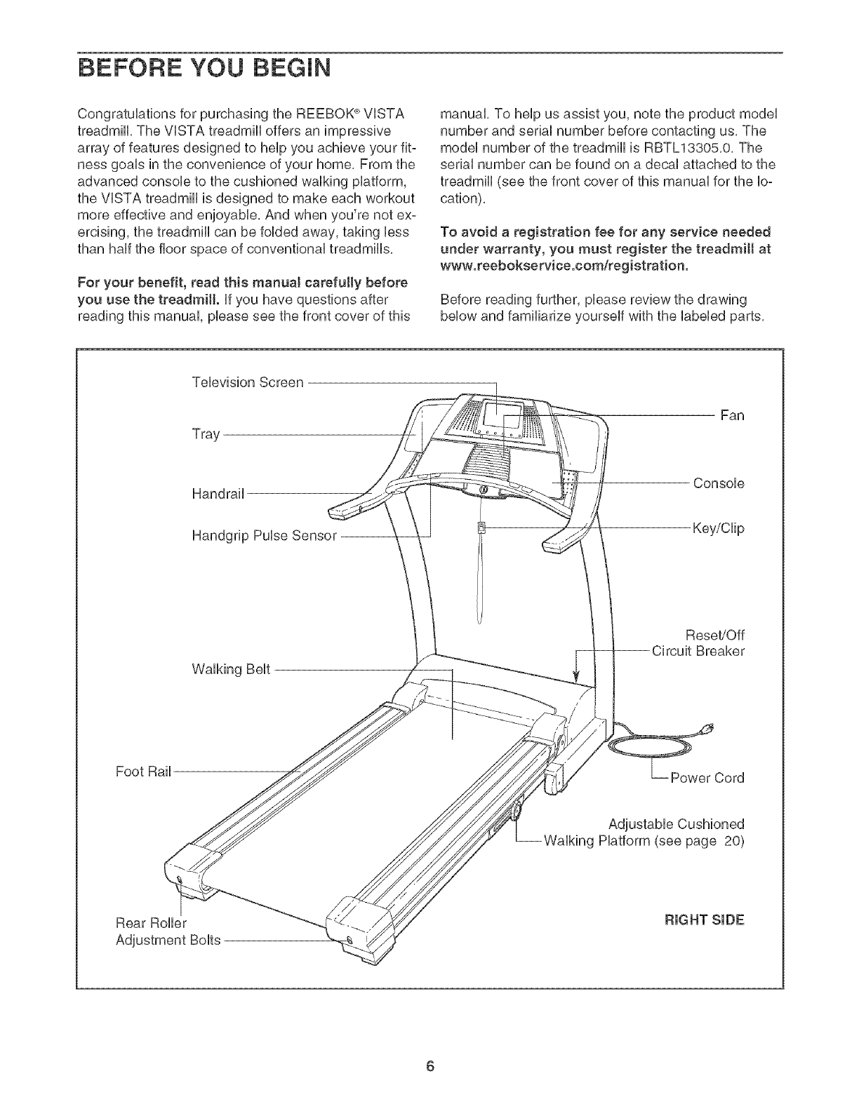
The decals shown here have been placed on the treadmill if a decal is missing, or
if it is not legibJe, caJ[ the toil-free telephone number on the front cover of this
manuaJ and order a free replacement decal Apply the decal in the tocation shown.
Note: The decaJs are not shown at actual size.
KEEP HANDSAND FEETAWAY
FROMTHISAREAWHILETHE
TREADMILLiS iN OPERATION.
Protect yourself and
others from risk of serious
injury, Read the user's
manual and :
,Stand only on the
slde laJls wrlen
stading or stopping
treadmill.
•Change speed in
small increments.
,Hold handrails to
operating treadmill.
.Slop if you feel faint,
dizzy, or short of
bleath.
• Fully engage storage
latch before tread-
mill is moved 0i
stored.
,Reduce incline to ils
lowest level before
folding treadmill into
storage position,
not in use,
,Keepclathing,
fingers, and hair
away frommoving
belt.
.Never lry to adiust
or fix the belt while
itis moving,
'Always wear
athlatic shoes while
operating treadmill.
5
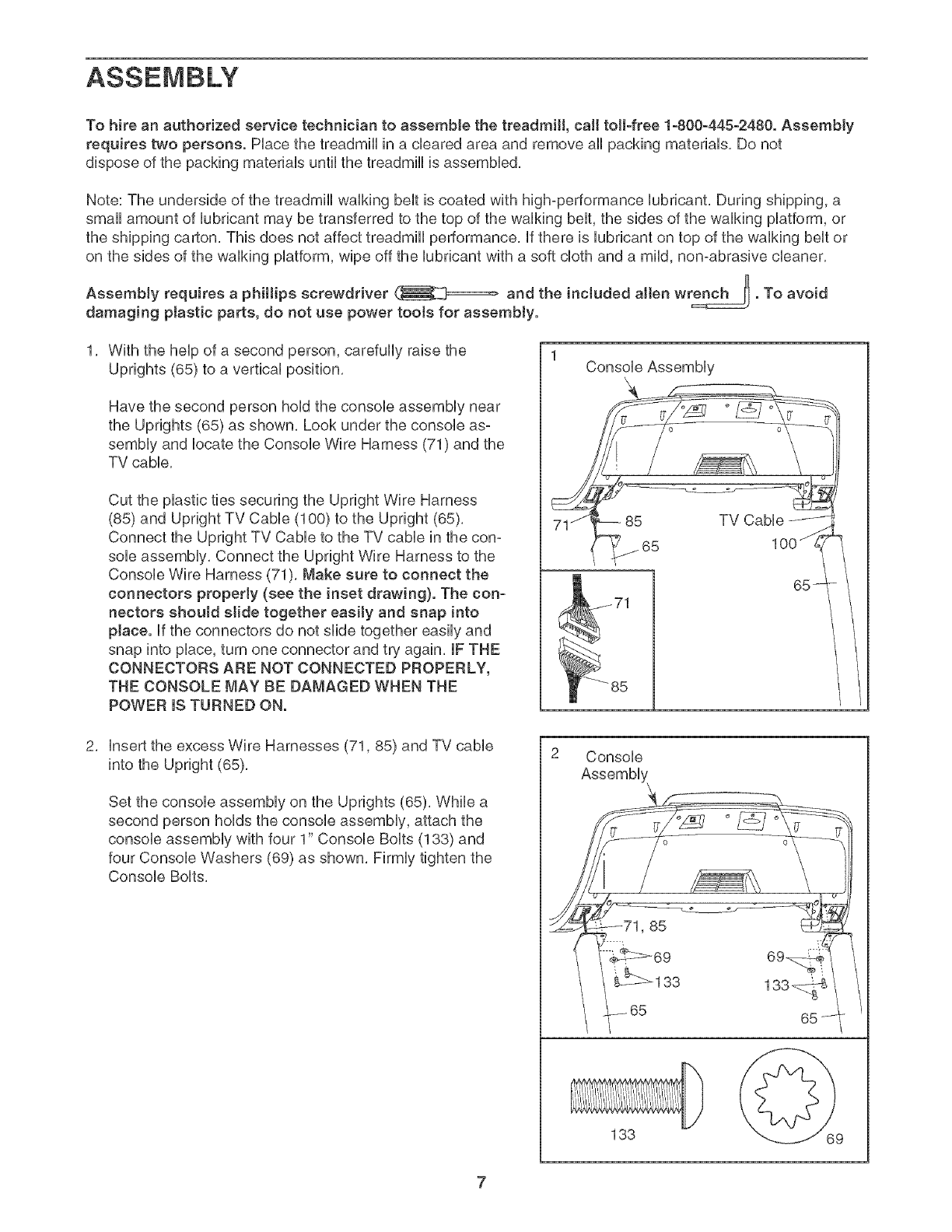
BEFORE YOU BEGIN
Congratulations for purchasing the REEBOK ®VISTA
treadmill, The VISTA treadmill offers an impressive
array of features designed to help you achieve your fit-
ness goals in the convenience of your home, From the
advanced console to the cushioned walking platform,
the VISTA treadmill is designed to make each workout
more effective and enjoyable, And when you're not ex-
ercising, the treadmill can be folded away, taking less
than half the floor space of conventional treadmills,
For your benefit, read this manual carefully before
you use the treadmill, if you have questions after
reading this manual, please see the front cover of this
manual, To help us assist you, note the product model
number and serial number before contacting us, The
model number of the treadmill is RBTL13305,0, The
serial number can be found on a decal attached to the
treadmill (see the front cover of this manual for the lo-
cation),
To avoid a registration fee for any service needed
under warranty, you must register the treadmill at
www.reebokservice.com/'registration.
Before reading further, please review the drawing
below and familiarize yourself with the labeled parts,
Television Screen
Tray
Fan
Handrail
Handgrip Pulse Sensor --
Console
Key/Clip
Walking Belt
Reset/Off
Breaker
Foot Rail Power Cord
Adjustable Cushioned
Walking Platform (see page 20)
Rear Roller
6
To hire an authorized service technician to assemble the treadmill, call toIFfree 1-800-445-2480. Assembly
requires two persons. Hace the treadmHUin a cbared area and remove aH packing materiaUs, Do not
dispose of the packing materiab until the treadmHUis assembbd,
Note: The underside of the treadmHUwaUking beUtis coated with high@erformance Uubrbant, During shipping, a
small amount of Uubrbant may be transferred to the top of the waUking beUt,the sides of the walking platform, or
the shipping carton, This does not affect treadmill performance, If there is lubricant on top of the walking belt or
on the sides of the walking platform, wipe off the lubricant with a soft cloth and a mild, non-abrasive cleaner,
AssemMy requires a phillips screwdriver and the included allen wrench _. To avoid
damaging ptastic parts, do not use power toots for assembly.
With the help of a second person, carefully raise the
Uprights (65) to a vertical position,
Have the second person hold the console assembly near
the Uprights (65) as shown, Look under the console as°
sembly and locate the Console Wire Harness (71) and the
TV cable,
Cut the plastic ties securing the Upright Wire Harness
(85) and Upright TV Cable (100) to the Upright (65),
Connect the Upright TV Cable to the TV cable in the con-
sole assembly, Connect the Upright Wire Harness to the
Console Wire Harness (71), Make sure to connect the
connectors properJy (see the inset drawing}. The con-
nectors shouJd slide together easiJy and snap into
place. If the connectors do not slide together easily and
snap into place, turn one connector and try again, IF THE
CONNECTORS ARE NOT CONNECTED PROPERLY,
THE CONSOLE MAY BE DAMAGED WHEN THE
POWER IS TURNED ON.
1Console Assembly
insert the excess Wire Harnesses (71,85) and TV cable
into the Upright (65),
Set the console assembly on the Uprights (65), While a
second person holds the console assembly, attach the
console assembly with four 1" Console Bolts (138) and
four Console Washers (69) as shown, Firmly tighten the
Console Bolts,
Console
i_71,85
133
133_
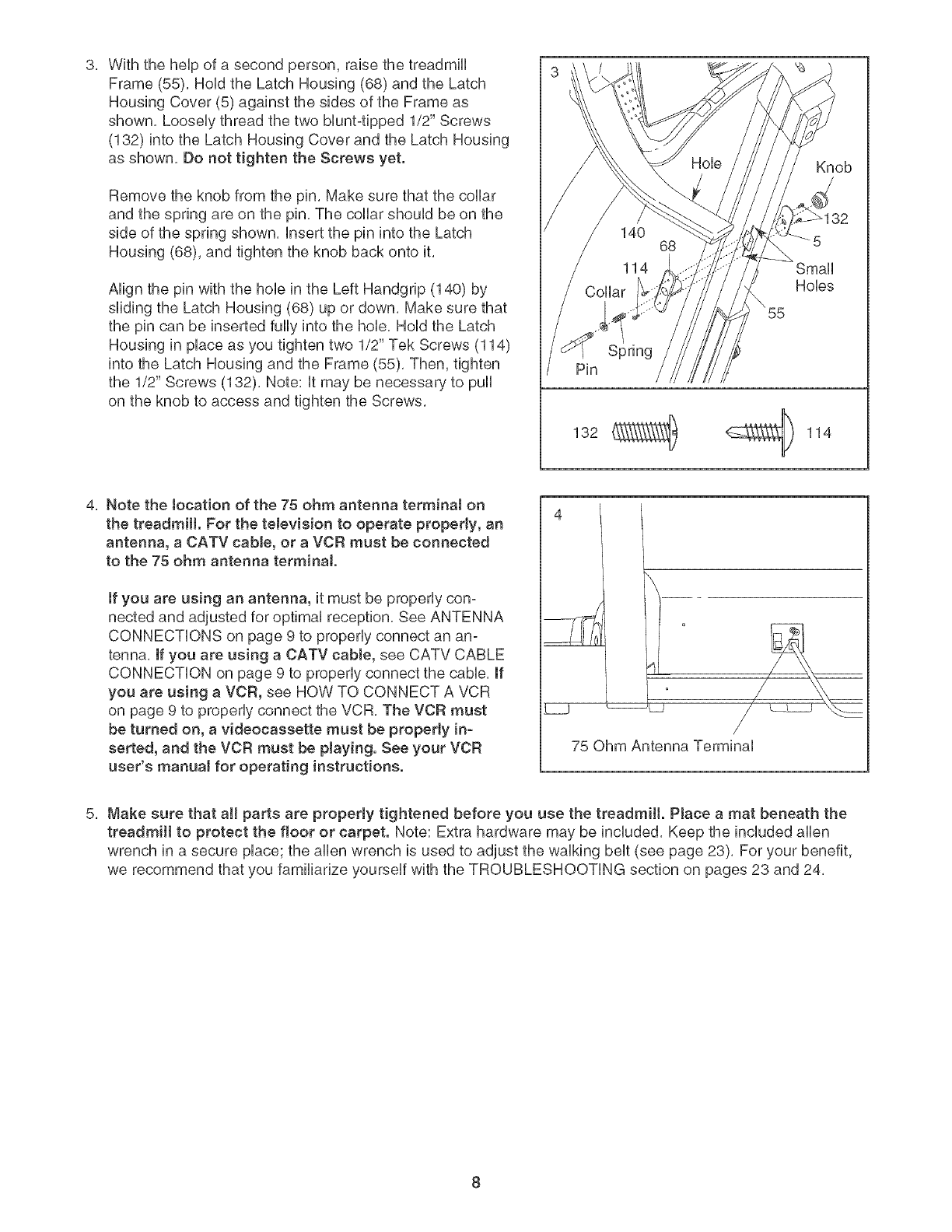
With the help of a second person, raise the treadmill
Frame (55), Hold the Latch Housing (68) and the Latch
Housing Cover (5) against the sides of the Frame as
shown, Loosely thread the two bluntqpped 1/2" Screws
(132) into the Latch Housing Cover and the Latch Housing
as shown, Do not tighten the Screws yet,
Remove the knob from the pin, Make sure that the collar
and the spring are on the pin, The collar should be on the
side of the spring shown, insert the pin into the Latch
Housing (68), and tighten the knob back onto it,
Align the pin with the hob in the Left Handgrip (140) by
sliding the Latch Housing (68) up or down, Make sure that
the pin can be inserted fully into the hob, Hold the Latch
Housing in place as you tighten two 1/2" Tek Screws (114)
into the Latch Housing and the Frame (55), Then, tighten
the 1/2" Screws (132), Note: it may be necessary to pull
on the knob to access and tighten the Screws,
Spring
Pin
132 _ _ 114
4
Knob
32
Small
Hobs
4, Note the tocation of the 75 ohm antenna terminaJ on
the treadmill. For the teJevision to operate properly, an
antenna, a CATV cable, or a VCR must be connected
to the 75 ohm antenna terminal.
if you are using an antenna, it must be properly con-
nected and adjusted for optimal reception, See ANTENNA
CONNECTIONS on page 9 to properly connect an an-
tenna, if you are using a CATV cable, see CATV CABLE
CONNECTION on page 9 to properly connect the cable, if
you are using a VCR, see HOW TO CONNECT A VCR
on page 9 to properly connect the VCR, The VCR must
be turned on, a videocassette must be property in-
serted, and the VCR must be playing. See your VCR
user's manual for operating instructions.
_.j _L_
75 Ohm Antenna Terminal
Make sure that aH parts are properly tightened before you use the treadmill. PJace a mat beneath the
treadmill to protect the floor or carpet. Note: Extra hardware may be induded, Keep the included allen
wrench in a secure place; the allen wrench is used to adjust the walking belt (see page 23), For your benefit,
we recommend that you familiarize yourself with the TROUBLESHOOTING section on pages 23 and 24,
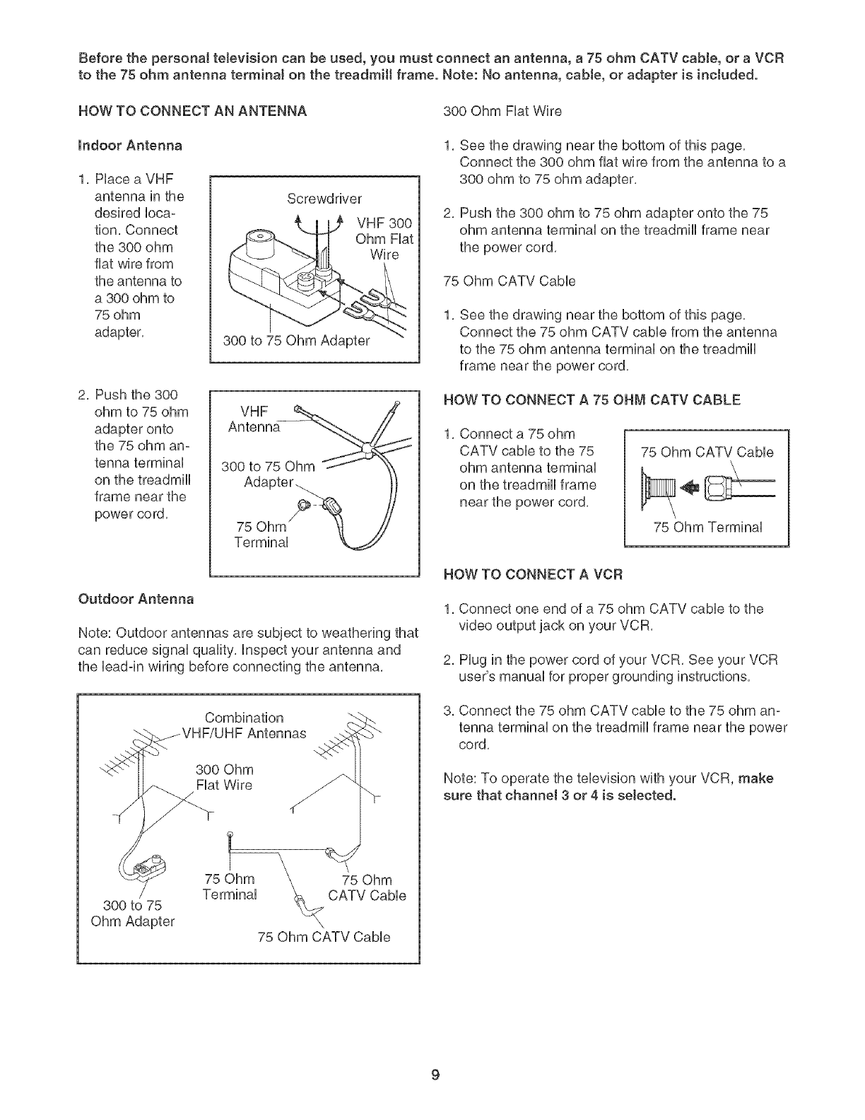
Beforethepersonaltelevisioncanbeused,youmustconnectanantenna,a 75ohmCATVcable,or aVCR
to the75ohmantennaterminalonthetreadmillframe.Note:Noantenna,cable,or adapteris included.
HOWTOCONNECTANANTENNA 300OhmFiatWire
Indoor Antenna
1. Place a VHF
antenna in the
desired loca-
tion. Connect
the 300 ohm
fiat wire from
the antenna to
a 300 ohm to
75 ohm
adapter.
Screwdriver
VHF 300
Ohm Fiat
Wire
300 to 75 Ohm Adapter
2. Push the 300
ohm to 75 ohm
adapter onto
the 75 ohm an-
tenna terminal
on the treadmill
frame near the
power co rd.
VHF
Antenna
300 to 75 Ohm
Adapter.
75 Ohm
Terminal
Outdoor Antenna
Note: Outdoor antennas are subject to weathering that
can reduce signal quality, inspect your antenna and
the bad-in wiring before connecting the antenna.
1. See the drawing near the bottom of this page.
Connect the 300 ohm fiat wire from the antenna to a
300 ohm to 75 ohm adapter.
2. Push the 300 ohm to 75 ohm adaptor onto the 75
ohm antenna terminal on the treadmill frame near
the power cord.
75 Ohm CATV Cabb
1, See the drawing near the bottom of this page.
Connect the 75 ohm CATV cabb from the antenna
to the 75 ohm antenna terminal on the treadmill
frame near the power cord.
HOW TO CONNECT A 75 OHM CATV CABLE
1. Connect a 75 ohm
CATV cable to the 75
ohm antenna terminal
on the treadmill frame
near the power cord.
75 Ohm CATV Cable
75 Ohm Terminal
HOW TO CONNECT A VCR
1, Connect one end of a 75 ohm CATV cable to the
video output jack on your VCR,
2, Plug in the power cord of your VCR, See your VCR
user's manual for proper grounding instructions,
Combination
300 Ohm
Fiat Wire
3. Connect the 75 ohm CATV cable to the 75 ohm an-
tenna terminal on the treadmill frame near the power
cord.
Note: To operate the television with your VCR, make
sure that channel 3 or 4 is selected.
300 to 75
Ohm Adapter
75 Ohm
CATV CaNe
75 Ohm CATV Cable
TREADMILL OPERATION
THE PRE-LUBRmCATED WALKmNG BELT
Your treadmHUfeatures a waUking beUtcoated with high°
performance Uubdcant, iMPORTANT: Never apply sil-
icone spray or other substances to the walking
bett or the walking platform. Such substances will
deteriorate the walking belt and cause excessive
wear.
HOW TO PLUG IN THE POWER CORD
DANGER: improper connection
of the equipment-grounding conductor can
result in an increased risk of electric shock.
Check with a qualified electrician or service-
man if you are in doubt as to whether the
product is propedy grounded. Do not modify
the plug provided with the product--if it wiJl
not fit the outlet, have a proper outlet
installed by a qualified eJectrician.
Your treadmill, like any other type of sophisticated
electronic equipment, can be seriously damaged by
sudden voltage changes in your home's power,
Voltage surges, spikes, and noise interference can
result from weather conditions or from other appliances
being turned on or off, To decrease the possibility of
your treadmill being damaged, always use a surge
suppressor with your treadmill (see drawing 1 at
the right}. To purchase a surge suppressor, see
your Joca! REEBOK dealer or call the toll-free teJe-
phone number on the front cover of this manuaJ
and order part number 146148, or see your tocaJ
electronics store.
Use onJy a singJe-ouflet surge suppressor that is
UL 1449 tisted as a transient voltage surge sup-
pressor (TVSS}. The surge suppressor must have a
UL suppressed voltage rating of 400 votts or Jess
and a minimum surge dissipation of 450 jouJes.
The surge suppressor must be electrically rated for
120 voffs AC and 15 amps. There must be a moni-
toring Jight on the surge suppressor to indicate
whether it is functioning properly. Failure to use a
properly functioning surge suppressor coutd resuJt
in damage to the control system of the treadmill. If
the control system is damaged, the walking beJt
may change speed, accelerate, or stop unexpect-
edly, which may resutt in a fall and serious injury.
This product must be grounded, if it should maffunc°
tion or break down, grounding provides a path of least
resistance for electric current to reduce the risk of ebc°
tric shock, This product is equipped with a cord having
an equipment-grounding conductor and a grounding
plug, Plug the power cord into a surge suppressor,
and plug the surge suppressor into an appropriate
outlet that is properly installed and grounded in
accordance with aH Jocat codes and ordinances.
important: The treadmill is not compatible with
GFCl-equipped outJets.
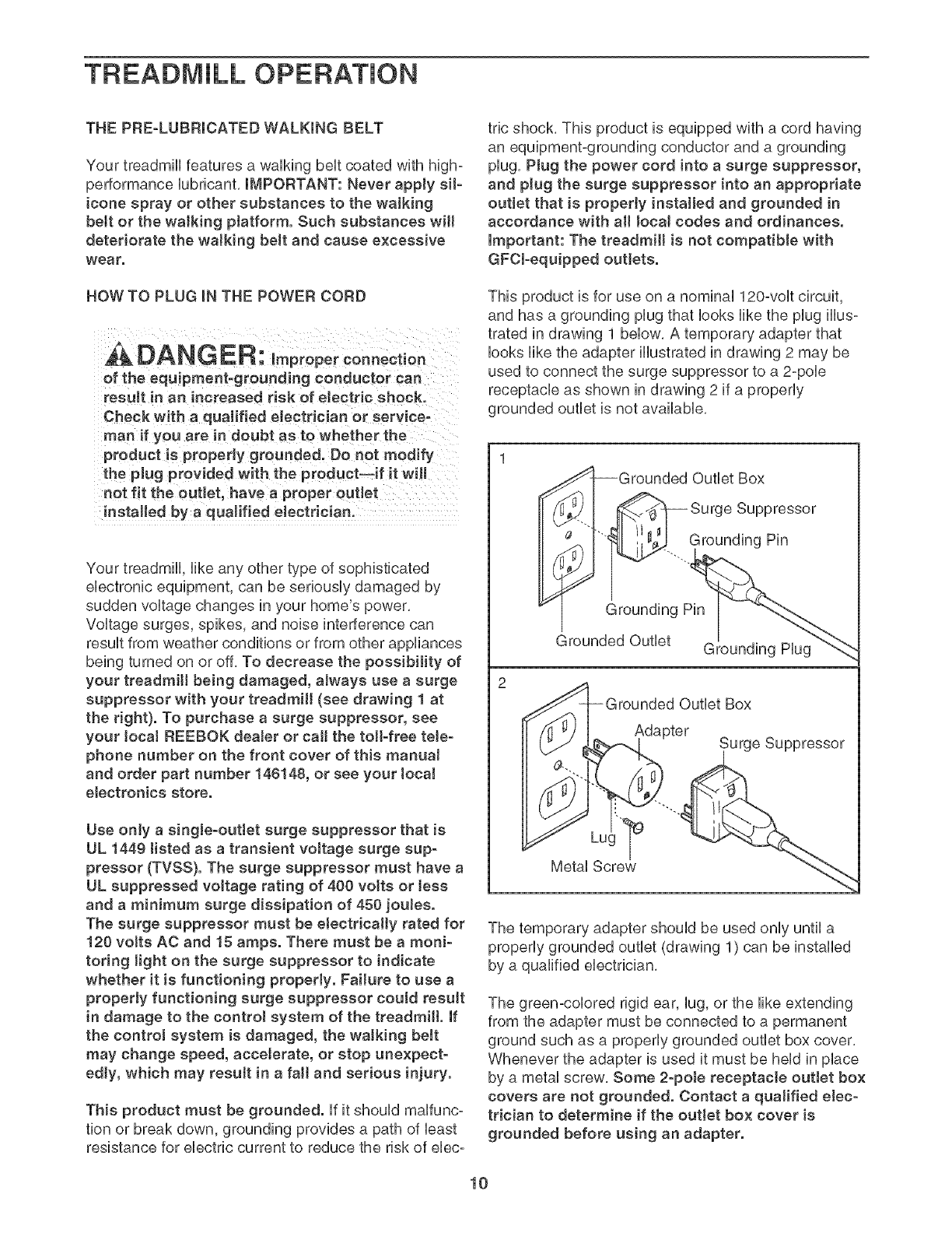
This product is for use on a nominal 120-volt circuit,
and has a grounding plug that looks like the plug illus-
trated in drawing 1 below, A temporary adapter that
looks like the adapter illustrated in drawing 2 may be
used to connect the surge suppressor to a 2-pole
receptacle as shown in drawing 2 if a properly
grounded outlet is not available,
I-Grounded Outlet Box
_"-I _ Surge Suppressor
.. Grounding Pin
_rounded Outlet Box
Adapter Surge Suppressor
The temporary adapter should be used only until a
properly grounded outlet (drawing 1) can be installed
by a qualified electrician,
The green-colored rigid ear, lug, or the like extending
from the adapter must be connected to a permanent
ground such as a properly grounded outlet box cover,
Whenever the adapter is used it must be held in place
by a metal screw, Some 2-poJe receptacle outJet box
covers are not grounded. Contact a quaJified elec-
trician to determine if the outlet box cover is
grounded before using an adapter.
10

_o (°°°°°
oooooo
oooooo
oooooo
oooooo
ooooo
ooooo L
r
oooo
\
'\ ............ )\................
f
FEATURES OF THE CONSOLE
The treadmill console offers an impressive array of
features designed to help you get the most from your
workouts.
When the manual mode of the console is selected, the
speed and incline of the treadmill can be changed with
the touch of a button. As you exercise, the console
will display continuous exercise feedback. You can
even measure your heart rate using the handgnp pulse
sensor.
In addition, the console offers ten preset programs.
Each program automatically controls the speed and in-
dine of the treadmill as it guides you through an effec-
tive workout. You can even create custom workout pro-
grams and store them in memory for future use.
Four heart rate programs are also offered. Each pro-
gram automatically adjusts the speed and incline of the
treadmill to keep your heart rate near target heart rate
settings while you exercise.
Whether you select the manual mode or a program,
you can enjoy the shows of your choice on the per-
sonal television while you get in shape.
To use the manuaJ mode of the console, follow the
steps beginning on page 12. To use a preset program,
see page 14. To create and use a custom program,
see pages 16 and 17. To use a heart rate program,
see page 18. To operate the personaJ television, see
page 20.
Note: If there is a sheet of clear plastic on the face of
the console, peel off the plastic. To prevent damage to
the walking platform, wear clean athletic shoes while
using the treadmill. The first time the treadmill is used,
observe the alignment of the walking belt, and center
the walking belt if necessary (see page 24).
11
Hug in the power cord (see page 10).
Next, bcate the reset/off
circuit breaker near the
power cord. Make sure that
the circuit breaker is in the
reset position.
Stand on the foot rails of the treadmill Find the dip at-
tached to the key (see the drawing on page 11) and at-
tach the dip secureUyto the waistband of your cbthes.
Next, insert the key into the consob. After a moment,
the dispUays wHUHght, and after a few seconds, the
tebvision wHUturn on. Important: In an emergency
situation, the key can be putted from the console,
causing the waJking belt to slow to a stop. Test the
clip by carefully taking a few steps backward until
the key is putled from the consoJe. If the key is not
pulled from the consoJe, adjust the position of the
clip as needed.
HOW TO USE THE MANUAL MODE
Insert the key into the console.
See HOW TO TURN ON THE POWER above.
I Select the manual mode.
When the key is inserted, the manual mode wiii be
selected, if you have selected a program, press
the Manual button to reselect the manual mode,
Start the walking belt.
To start the walking belt, press the Start button,
the Speed increase button, or one of the twelve
numbered Speed buttons.
if the Start button or the Speed increase button is
pressed, the walking belt wiii begin to move at 1
mph, As you exercise, change the speed of the
walking belt as desired by pressing the Speed in-
crease and decrease buttons, Each time a button
is pressed, the speed setting will change by 0,1
mph; if a button is held down, the speed setting
wiii change in increments of 0,5 mph, Note: After
the buttons are pressed, it may take a moment for
the walking belt to reach the selected speed setting,
if one of the numbered Speed buttons is pressed,
the walking belt will gradually increase in speed
until it reaches the selected speed setting.
To stop the walking belt, press the Stop button.
The time will begin to flash in the left display. To
restart the walking belt, press the Start button, the
Speed increase button, or one of the numbered
Speed buttons.
Change the incline of the treadmill as desired.
To change the incline of the treadmill, press the
Incline buttons, Each time a button is pressed, the
incline will change by 0,5%, To change the incline
setting quickly, press the numbered Incline buttons,
Note: After the buttons are pressed, it may take a
moment for the treadmill to reach the selected in-
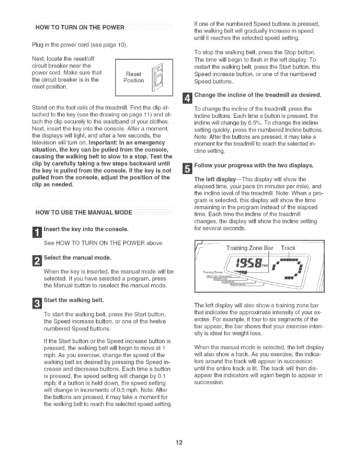
Fottow your progress with the two displays.
The left display--This display will show the
elapsed time, your pace (in minutes per mile), and
the incline level of the treadmill. Note: When a pro-
gram is selected, this display wiii show the time
remaining in the program instead of the elapsed
time, Each time the incline of the treadmill
changes, the display will show the incline setting
for several seconds,
Training Zone Bar Track
The left display wiii also show a training zone bar
that indicates the approximate intensity of your ex-
ercise, For example, if four to six segments of the
bar appear, the bar shows that your exercise inten-
sity is ideal for weight loss,
When the manual mode is selected, the left display
wiii also show a track, As you exercise, the indica-
tors around the track wiii appear in succession
until the entire track is lit, The track will then dis-
appear the indicators wiii again begin to appear in
Succession,
12

The right dispJay--Thb display will show the dis-
tance that you have walked or run, the number of
1/4-mib laps you have compbted, the speed of
the walking belt, and the approximate numbers of
c31ofiesand @t c31o,des"you have burned (see
FAT BURNING on page 25),
The right display will also show your heart rate
when you use the handgrip pulse sensor, in addi-
tion, during heart rate programs the right display
will show a heart rate bar that shows your heart
rate as a percentage of your estimated maximum
heart rate (see step 3 on page 18 for an explana-
tion of your estimated maximum heart rate), For
example, if four to six segments of the bar appear,
your heart rate is between 60% and 70% of your
estimated maximum heart rate,
Note: The console can display speed and dis-
tance in either miles or kilometers, The letters
"MPH" or "KIn/H" wiii appear in the right display to
show which unit of measurement is selected, To
change the unit of measurement, see HOW TO
USE THE iNFORMATiON MODE on page 20, For
simplicity, all instructions in this section refer
to miles.
To reset the displays, press the Stop button, re-
move the key, and then reinsert the key,
Measure your heart rate if desired.
Before using
the handgrip
pulse sensor,
remove the
sheets of clear
plastic from the
metal contacts, Contacts
make sure that your hands are clean, Next, hold
the handgrip pulse sensor with your palms resting
on the metal contacts; avoid moving your hands,
When your pulse is detected, the heart-shaped in-
dicator in the right display will flash each time your
heart beats, one or two dashes (- -) will appear,
and then your heart rate will be shown, For the
most accurate heart rate reading, continue to
hold the contacts for about 15 seconds.
Note: The handgrip pulse sensor is intended to be
used only for heart rate measurement, Do not
use the handgdp puJse sensor as a handJebar.
AJways hoJd the handrails for support when
you are not measuring your heart rate.
Turn on the fan if desired.
To turn on the fan, press the button below the fan,
To turn on the fan at high speed, press the button
a second time, To turn off the fan, press the but-
ton a third time, Note: if the fan is on when the
walking belt is stopped, the fan will automatically
turn off after a few minutes,
When you are finished exercising, remove the
key from the console.
Step onto the foot rails, press the Stop button, and
adjust the incline of the treadmill to the lowest
setting. The incline must be at the lowest setting
when the treadmill is fotded to the storage posi-
tion or the treadmill will become damaged. Next,
remove the key from the console and put it in a se-
cure place, Note: If the dispJays remain Jit after
the key is removed, the consote is in the
"demo" mode. See NOW TO USE THE INFOR-
MATION MODE on page 20 and turn off the
demo mode.
When you are finished using the treadmill,
switch the reseL/off circuit breaker to the "off"
position and unptug the power cord.
13
NOW TO USE A PRESET PROGRAM
mnsert the key into the console.
See HOW TO TURN ON THE POWER on
page 12.
Select a preset program.
To select a preset program, press the Speed &
Incline Programs button repeatedly. The right dis-
play will show which preset program (P-1 through
P-IO) is selected.
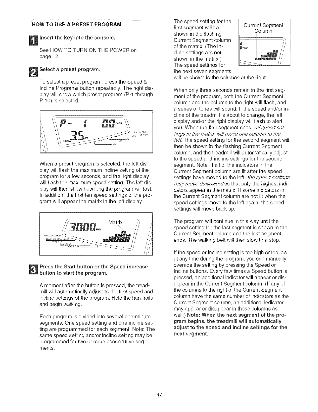
When a preset program is selected, the left dis-
play will flash the maximum incline setting of the
program for a few seconds, and the right display
will flash the maximum speed setting. The left dis-
play will then show how long the program will last.
in addition, the first ten speed settings of the pro-
gram will appear the matrix in the left display.
Press the Start button or the Speed increase
button to start the program.
A moment after the button is pressed, the tread-
mill will automatically adjust to the first speed and
incline settings of the program, Hold the handrails
and begin walking,
Each program is divided into several one-minute
segments, One speed setting and one incline set-
ting are programmed for each segment, Note: The
same speed setting and/or incline setting may be
programmed for two or more consecutive seg-
ments,
The speed setting for the
first segment wiii be
shown in the flashing
of the matrix, (The in-
cline settings are not
shown in the matrix,)
Current Segment
Column
....... i
the next seven segments
wiii be shown in the columns at the right.
When only three seconds remain in the first seg-
ment of the program, both the Current Segment
column and the column to the right wiii flash, and
a series of tones will sound, if the speed and/or in-
cline of the treadmill is about to change, the left
display and/or the right display wiii flash to alert
you, When the first segment ends, aiispeedeeio
t/hde in the maLrix will move one column to the
iei:Z The speed setting for the second segment will
then be shown in the flashing Current Segment
column, and the treadmill will automatically adjust
to the speed and incline settings for the second
segment. Note: If all of the indicators in the
Current Segment column are lit after the speed
settings have moved to the left, the epeedee#/bge
maymove d'o_qY/ardso that only the highest indi-
cators appear in the matrix. If some indicators in
the Current Segment column are not lit when the
speed settings move to the left again, the speed
settings will move back up.
The program wiii continue in this way until the
speed setting for the last segment is shown in the
Current Segment column and the last segment
ends, The walking belt wiii then slow to a stop,
if the speed or incline setting is too high or too low
at any time during the program, you can manually
override the setting by pressing the Speed or
Incline buttons, Every few times a Speed button is
pressed, an additional indicator wiii appear or dis-
appear in the Current Segment column, (if any of
the columns to the right of the Current Segment
column have the same number of indicators as the
Current Segment column, an additional indicator
may appear or disappear in those columns as
well.) Note: When the next segment of the pro-
gram begins, the treadmill will automatically
adjust to the speed and incline settings for the
next segment,
14

To stop the program at any time, press the Stop
button, The time wiii begin to flash in the left dis°
play, To restart the program, press the Start button
or the Speed increase button, The walking belt will
begin to move at 1 mph, When the next segment
of the program begins, the treadmill will automati-
cally adjust to the speed and incline settings for the
next segment,
Follow your progress with the displays.
See step 5 on page 12,
Measure your heart rate if desired.
See step 6 on page 13,
Turn on the fan if desired.
See step 7 on page 13,
When you are finished exercising, remove the
key from the console.
When the program ends, make sure that the in-
cJine of the treadmill is at the lowest setting.
Next, remove the key from the console and put it in
a secure place, Note: If the displays and various
indicators remain Ht after the key is removed,
the console is in the "demo" mode. See HOW
TO USE THE mNFORMATmONMODE on page 20
and turn off the demo mode.
When you are finished using the treadmill,
switch the reset/off circuit breaker to the "off"
position and unplug the power cord.
15
HOW TO CREATE A CUSTOM _ROGRAM
insert the key into the console.
See HOW TO TURN ON THE POWER on
page 12.
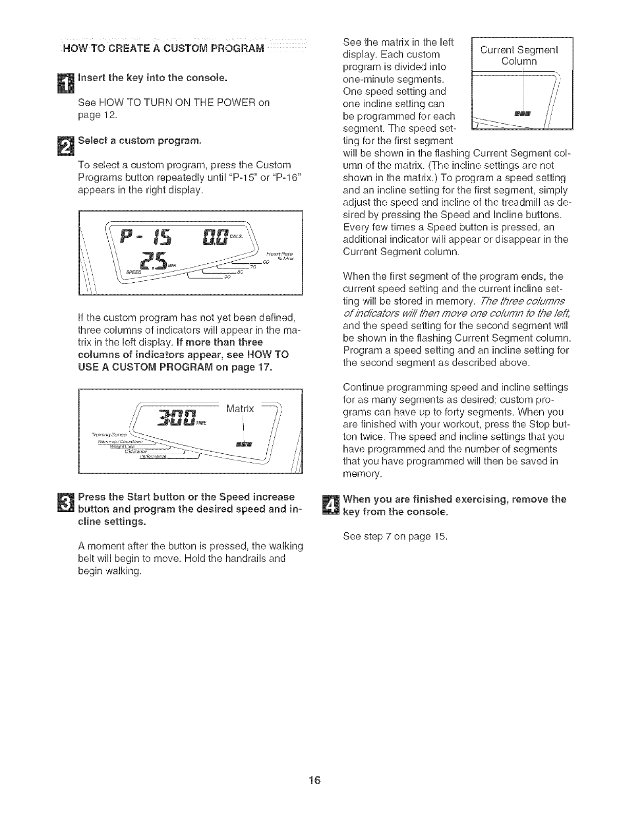
Select a custom program.
To sebct a custom program, press the Custom
Programs button repeatedUy until "P-15" or "P-16"
appears in the right dispUay.
IP
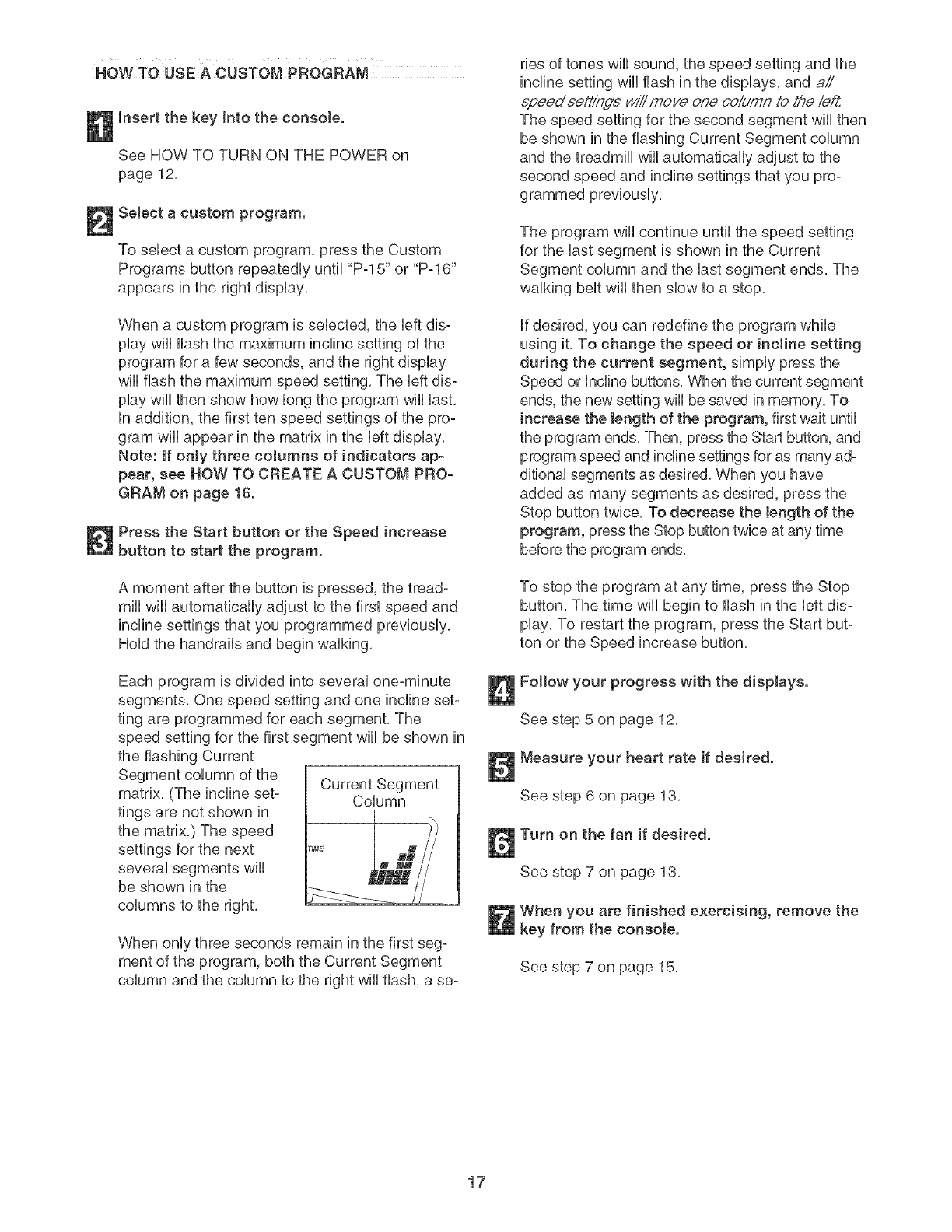
ff the custom program has not yet been defined,
three coUumns of indicators wHUappear in the ma-
trix in the bft dispUay. If more than three
cotumns of indicators appear, see HOW TO
USE A CUSTOM PROGRAM on page 17.
Matrix
/
/
/
//
//
Press the Start button or the Speed increase
button and program the desired speed and in-
cJine settings.
A moment after the button is pressed, the walking
belt will begin to move. Hold the handrails and
begin walking.
See the matrix in the left
display. Each custom
program is divided into
One speed setting and
one incline setting can
be programmed for each
segment, The speed set-
ting for the first segment
Column
wiii be shown in the flashing Current Segment cop
umn of the matrix, (The incline settings are not
shown in the matrix,) To program a speed setting
and an incline setting for the first segment, simply
adjust the speed and incline of the treadmill as de-
sired by pressing the Speed and Incline buttons,
Every few times a Speed button is pressed, an
additional indicator wiii appear or disappear in the
Current Segment column,
When the first segment of the program ends, the
current speed setting and the current incline set-
ting will be stored in memory. The th;'ee coiumn.£
ofin_oalorswiiit/_enmove one coiumn 1othe left,
and the speed setting for the second segment wiii
be shown in the flashing Current Segment column.
Program a speed setting and an incline setting for
the second segment as described above.
Continue programming speed and incline settings
for as many segments as desired; custom pro-
grams can have up to forty segments, When you
are finished with your workout, press the Stop but-
ton twice, The speed and incline settings that you
have programmed and the number of segments
that you have programmed wiii then be saved in
memory,
When you are finished exercising, remove the
key from the consote.
See step 7 on page 15.
16
HOW TO USEA CUSTOM PROGRAM
insert the key into the console.
See HOW TO TURN ON THE POWER on
page 12,
Select a custom program.
To sebct a custom program, press the Custom
Programs button repeatedUy until "P-15" or "P-16"
appears in the right dispUay,
When a custom program is sebcted, the bft dis-
pUaywHUflash the maximum incline setting of the
program for a few seconds, and the right dispUay
wHUflash the maximum speed setting, The bft dis-
pUaywHUthen show how bng the program wHUUast,
in addition, the first ten speed settings of the pro-
gram wHUappear in the matrix in the bft display,
Note: if only three coJumns of indicators ap_
pear, see HOW TO CREATE A CUSTOM PRO-
GRAM on page 16.
Press the Start button or the Speed increase
button to start the program.
A moment after the button is pressed, the tread-
mill will automatically adjust to the first speed and
incline settings that you programmed previously,
Hold the handrails and begin walking,
Each program is divided into several one-minute
segments, One speed setting and one incline set-
ting are programmed for each segment, The
speed setting for the first segment wiii be shown in
the flashing Current
Current Segment
matrix, (The incline set- Column
tings are not shown in
the matrix,) The speed
settings for the next
several segments will
be shown in the
columns to the right,
When only three seconds remain in the first seg-
ment of the program, both the Current Segment
column and the column to the right wiii flash, a se-
ries of tones wiii sound, the speed setting and the
incline setting will flash in the displays, and aii
epeed sett/ngs will move one ooldmn to the/e_Z
The speed setting for the second segment will then
be shown in the flashing Current Segment column
and the treadmill will automatically adjust to the
second speed and incline settings that you pro-
grammed previously,
The program wiii continue until the speed setting
for the last segment is shown in the Current
Segment column and the last segment ends, The
walking belt wiii then slow to a stop,
if desired, you can redefine the program while
using it, To change the speed or incline setting
during the current segment, simply press the
Speed or Incline buttons, When the current segment
ends, the new setting will be saved in memory, To
increase the Jength of the program, first wait until
the program ends, Then, press the Start button, and
program speed and incline settings for as many ad-
ditional segments as desired, When you have
added as many segments as desired, press the
Stop button twice, To decrease the bngth of the
program, press the Stop button twice at any time
before the program ends,
To stop the program at any time, press the Stop
button, The time wiii begin to flash in the left dis-
play, To restart the program, press the Start but-
ton or the Speed increase button,
Fottow your progress with the displays.
See step 5 on page 12,
Measure your heart rate if desired.
See step 6 on page 13,
Turn on the fan if desired.
See step 7 on page 13,
When you are finished exercising, remove the
key from the consote.
See step 7 on page 15,
17

HOWTO USE A HEART RATE PROGRAM
mfyou have heart prob-
lems, or if you are over 60 years of age and
have been inactive, do not use the heart rate
programs, if you are taking medication reguo
larly, consult your physician to find whether
the medication will affect your exercise heart
rate.
Enter your age.
When a heart rate program is seUected, the word
"AGE" and the current age setting wHUbegin to
flash in the right dispUay, Ufyou have aUready en-
tered your age, press the Enter button, ff you have
not entered your age, press the + or- button be-
side the Enter button to enter your age, and then
press the Enter button,
I
Follow the steps beUowto use a heart rate program,
Insert the key into the console.
See HOW TO TURN ON THE POWER on
page 12,
Select a heart rate program.
To seUecta heart rate program, press the Heart
Rate Control Programs button repeatedUy until
"P-11 ," "P-12," "P-13," or "P-14" appears in the
right display,
Enter a target heart rate setting for the program.
If heart rate program 11 is selected, the letters
"PLS" and the target heart rate setting for the pro-
gram will begin to flash in the right display, If de-
sired, change the target heart rate setting by
pressing the + or- button beside the Enter button
(see EXERCISE INTENSITY on page 25). Then,
press the Enter button,
If heart rate program 11 is selected, a pulse
symbol will scroll across the matrix in the left dis-
play, If heart rate program !2, 13, or 14 is se-
lected, a profile of the target heart rate settings of
the program will appear in the matrix in the left
display,
Note: During heart rate program 11, your heart
rate will remain near a target heart rate setting
that you select, During heart rate programs !2,
13, or 14, your heart rate will reach approximately
85% of your es'timated'maximum heaft,_te, Note:
Your maximum heart rate is estimated by sub-
tracting your age from 220, For example, if you
are 30 years old, your estimated maximum heart
rate is 190 beats per minute (220 - 30 = 190),
If heart rate program 12, 13, or 14 is selected,
the letters "PLS" and the maximum target heart
rate setting for the program will begin to flash in
the right display, if desired, change the maximum
target heart rate setting by pressing the + or - but-
ton beside the Enter button (see EXERCISE IN-
TENSITY on page 25). Then, press the Enter but-
ton, Note: if the maximum target heart rate setting
is changed, the intensity level of the entire pro-
gram will change,
18
Hotd the handgdp pulse sensor.
it is not necessary to hold the handgrip pulse sen-
sor continuously during a pulse program; how-
ever, you must hold the handgrip pulse sensor fie-
quently, Each time you hold the handgdp pulse
sensor, keep your hands on the metaJ con-
tacts for at least 15 seconds. Note: When you
are not hoUdingthe handgrip pube sensor, the bt-
ters "PLS" wHUappear in the dispUay instead of
your heart rate,
Press the Start button or the Speed increase
button to start the program.
A moment after the button is pressed, the tread-
mill will automatically adjust to the first speed and
incline settings of the program, Hold the handrails
and begin walking,
Heart rate program 11 is divided into several
one-minute segments, The same target heart rate
setting is programmed for all segments, (For a
shorter workout, simply stop the program before it
ends,) Heart rate programs 12, !3, and 14 are
divided into either 20 or 30 one-minute segments,
One target heart rate setting is programmed for
each segment, Note: The same target heart rate
setting may be programmed for two or more con-
secutive segments,
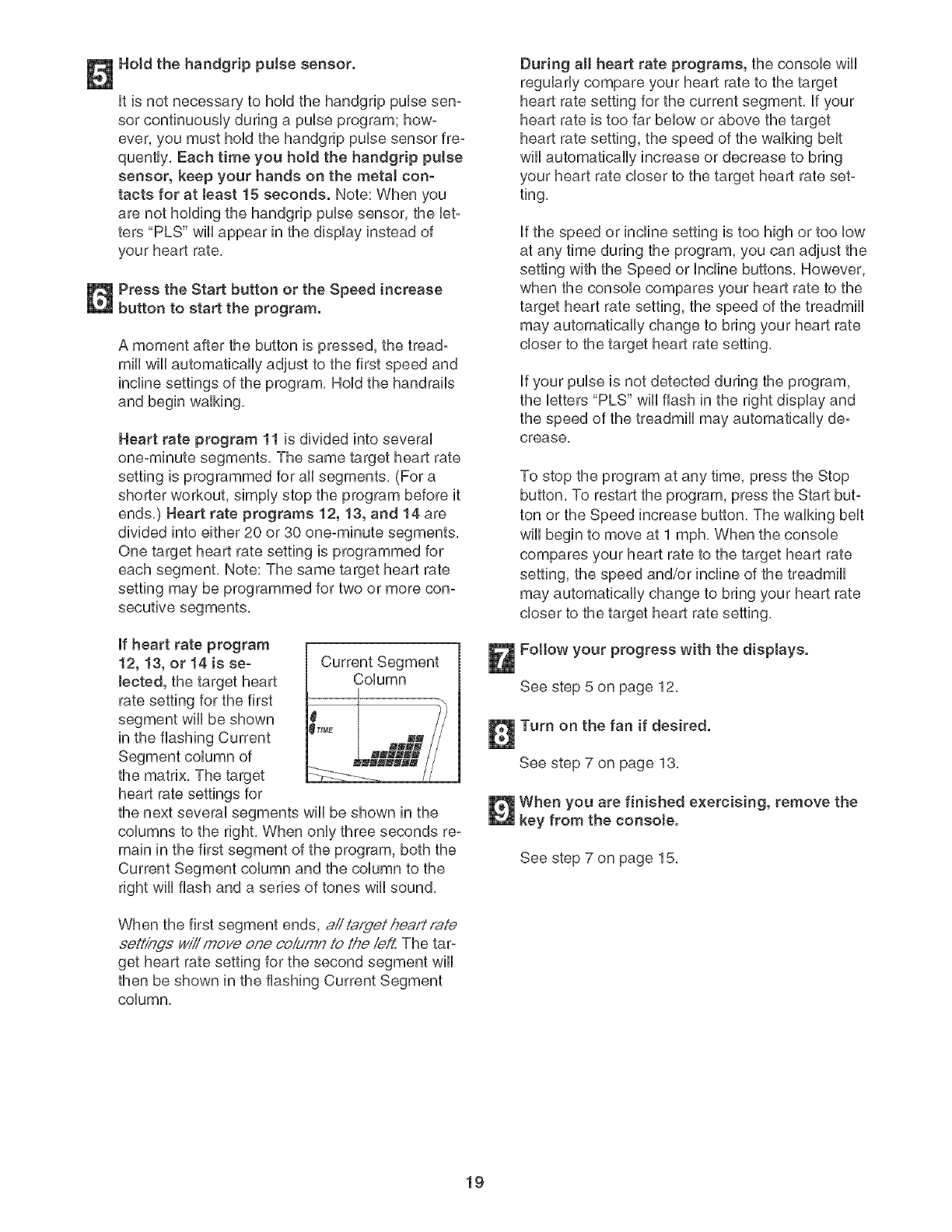
If heart rate program
12, 13, or 14 is se-
lected, the target heart
rate setting for the first
segment will be shown
in the flashing Current
Current Segment
Column
the matrix, The target
heart rate settings for
the next several segments will be shown in the
columns to the right, When only three seconds re-
main in the first segment of the program, both the
Current Segment column and the column to the
right will flash and a series of tones will sound,
When the first segment ends, aii t,.q,fgethea/://'ate
.¢eh'/nds wiii moye one co,_4mnto the ie/Z The tar=
get heart rate setting for the second segment will
then be shown in the flashing Current Segment
column,
During a[[ heart rate programs, the console wili
regularly compare your heart rate to the target
heart rate setting for the current segment, if your
heart rate is too far below or above the target
heart rate setting, the speed of the walking belt
wiil automatically increase or decrease to bring
your heart rate closer to the target heart rate set-
ting,
if the speed or incline setting is too high or too low
at any time during the program, you can adjust the
setting with the Speed or Incline buttons, However,
when the console compares your heart rate to the
target heart rate setting, the speed of the treadmill
may automatically change to bring your heart rate
closer to the target heart rate setting,
if your pulse is not detected during the program,
the letters "PLS" will flash in the right display and
the speed of the treadmill may automatically de-
crease,
To stop the program at any time, press the Stop
button, To restart the program, press the Start but-
ton or the Speed increase button, The walking belt
will begin to move at 1 mph, When the console
compares your heart rate to the target heart rate
setting, the speed and/or incline of the treadmill
may automatically change to bring your heart rate
closer to the target heart rate setting,
Fottow your progress with the displays.
See step 5 on page 12,
Turn on the fan if desired.
See step 7 on page 13,
When you are finished exercising, remove the
key from the consote.
See step 7 on page 15,
19
HOWTO OPERATE THE PERSONAL TELEVISION NOW TO USE THEmNFORMATmON MODE
iMPORTANT: Before operating the television, you
must connect an antenna, a 75 ohm CATV cable, or
a VCR to the 75 ohm antenna termina[ on the tread-
mill. See page 9 for instructions.
FoHHowthe steps bellow to operate the television,
insert the key into the console.
See HOW TO TURN ON THE POWER on page
12,
Press the Power button to turn on the
television.
When the key is inserted, the television wHi auto°
matbaHHyturn on, if you have turned off the televi-
sion, turn it on by pressing the Power button,
Press the Channel buttons to select the
desired channel.
When the television is turned on, the screen wii[
show the last channel that was selected, To select
a different channel press the Channei buttons,
The selected channei number wHiappear on the
screen for a few seconds, Note: The television is
equipped with a channei memorizing function that
allows you to go directly from the current channei
to the next channei saved in memory, Before
channeis can be selected in this way, they must
be saved in the television's memory, See HOW
TO USE THE iNFORMATiON MODE at the right,
Press the Volume buttons to adjust the volume.
When either Volume button is pressed, the vol-
ume level indicator wili appear on the screen for a
few seconds, To temporarily mute the sound,
press the Mute button, Press the Mute button
again to listen to the television, Note: To use ear-
phones or headphones (not included), plug them
into the headphone jack on the console,
When you are finished using the television,
press the Power button.
Press the Power button to turn off the television,
Note: Removing the key from the console will also
turn off the television,
The console features an information mode that allows
you to view treadmill usage information, select a sys-
tem of measurement for the console, and turn on and
turn off the demo mode, The information mode also al-
lows you to adjust the settings of the television and to
save channels into the television's memory,
Follow the steps below to use the information mode,
Hold down the Stop button while inserting the
key into the consoIe.
When the information mode is selected, the left
display wili show the total number of hours that the
treadmill has been used, The right display wiii
show the total number of miles or kilometers that
the walking belt has moved,
in addition, the right display wiil show the letter "E"
for English miles or the letter "M" for metric kilome-
ters, Press the Speed increase button to change
the unit of measurement if desired,
IMPORTANT: if the letter "d" appears in the right
display, the "demo" mode is selected, This mode
is intended to be used only when a treadmill is
displayed in a store, When the demo mode is se°
lected, the power cord can be plugged in, the key
can be removed from the console, and the dis°
plays and indicators on the console wiil automati-
cally light in a preset sequence, The buttons on
the console wiii not function, If a "d" appears in
the right display when the information mode is
selected, press the Speed decrease button.
Press the Power button and adjust the
brightness, contrast, color, sharpness, and/or
hue of the television.
When the Power button is pressed, the brightness
level indicator wili appear on the television screen,
Press the Volume buttons to adjust the brightness
setting if desired,
Next, press the Channel buttons until the contrast,
color, sharpness, or hue level indicator appears,
Adjust the settings, if desired, by pressing the
Volume buttons,
2O
Press the Power button again and add or
delete channels.
After aH valid channeUs avaHabb in your area have
been saved into the tebvbion's memory (see step
5 on page 21), you can manually add channeUs or
debte unwanted channeUs,
To add or debte a channel first press the
ChanneU buttons until the desired channeU number
appears on the screen, Then, press the VoUume
increase button to add the channel or the VoUume
decrease button to debte the channel Continue
this process until you have added aHdesired
channeUs and debted aH unwanted channeb,
Press the Power button again and setect an
antenna connection or a cable connection.
After the Power button is pressed, press the
VoUumedecrease button to sebct the Air setting,
the VoUume increase button to select the Standard
Cable setting, the Channel decrease button to se-
bct the Cable IRC setting, or the Channel in-
crease button to select the Cable HRC setting,
Note: The setting that you select will not appear
on the screen, If you have connected an antenna
to the treadmill, the Air setting should be selected,
If you have connected a CATV cable, one of the
three Cable settings should be selected; try all
three Cable settings, if necessary, to find the opti-
mal setting,
Press the Power button again and save
channels into the television's memory.
When the Power button is pressed, the television
will begin scanning all of the channels available in
your area, When no broadcast signal is detected
on a channel, the channel will be skipped, When a
broadcast signal is detected, the channel will be
saved into memory and the next channel will be
selected, This process will continue until the high°
est channel is reached, Do not remove the key
while the television is scanning channels.
When you are finished using the information
mode, remove the key.
To exit the information mode at any time (except
while the television is scanning channels), remove
the key from the console,
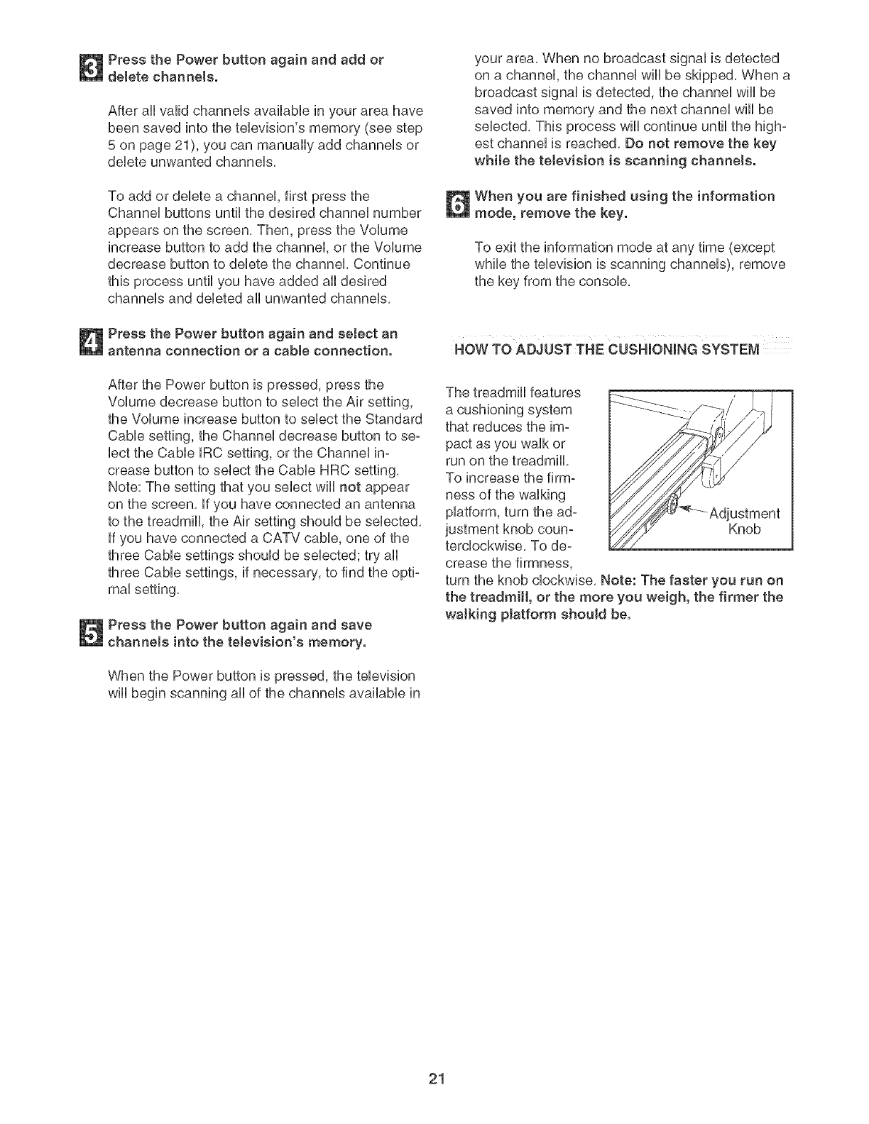
The treadmill features
a cushioning system
that reduces the im-
pact as you walk or
run on the treadmill
To increase the firm°
ness of the walking
platform, turn the ad-
justment knob eoun- Knob
tercloekwise, To de°
crease the firmness,
turn the knob clockwise, Note: The faster you run on
the treadmill, or the more you weigh, the firmer the
walking ptatform should be.
21
HOW TO FOLD AND MOVE THE TREADMILL
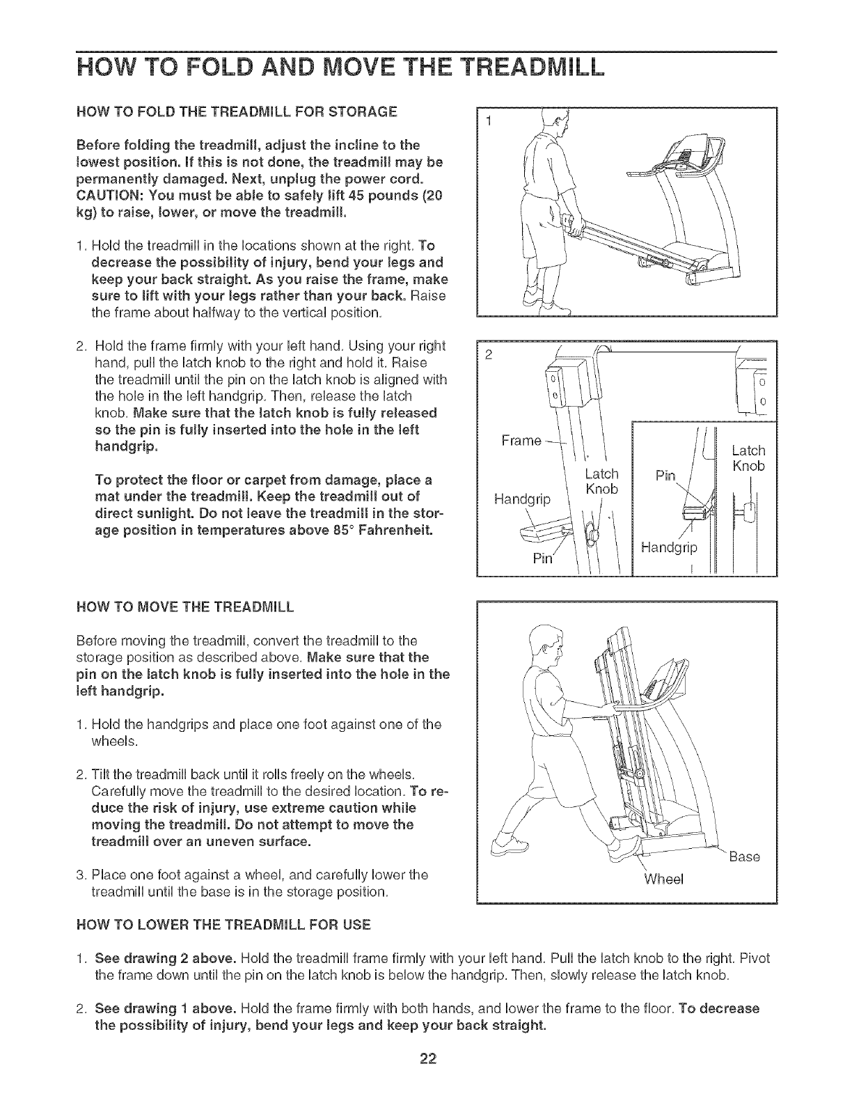
HOW TO FOLD THE TREADMmLL FOR STORAGE
Before folding the treadmill, adjust the incline to the
towest position, ff this is not done, the treadmill may be
permanentJy damaged. Next, unplug the power cord.
CAUTmON: You must be able to safely tift 45 pounds (20
kg) to raise, tower, or move the treadmill.
1, HoUdthe treadmHUin the bcations shown at the right, To
decrease the possibility of injury, bend your legs and
keep your back straight. As you raise the frame, make
sure to lift with your tegs rather than your back. Raise
the frame about haffway to the vertical position,
2, Hold the frame firmly with your left hand, Using your right
hand, pull the latch knob to the right and hold it, Raise
the treadmill until the pin on the latch knob is aligned with
the hole in the left handgrip, Then, release the latch
knob, Make sure that the latch knob is fully reJeased
so the pin is fully inserted into the hote in the teft
handgrip.
To protect the floor or carpet from damage, place a
mat under the treadmill. Keep the treadmill out of
direct sunJight. Do not leave the treadmill in the stor-
age position in temperatures above 85° Fahrenheit.
Frame --
Latch
Knob
Handgrip
Latch
Knob
HOW TO MOVE THE TREADMILL
Before moving the treadmill, convert the treadmill to the
storage position as described above, Make sure that the
pin on the Jatch knob is fully inserted into the hote in the
[eft handgrip.
1, Hold the handgrips and place one foot against one of the
wheels,
2, Tilt the treadmill back until it rolls freely on the wheels,
Carefully move the treadmill to the desired location, To re-
duce the risk of injury, use extreme caution while
moving the treadmill. Do not attempt to move the
treadmill over an uneven surface.
3, Place one foot against a wheel, and carefully lower the
treadmill until the base is in the storage position,
HOW TO LOWER THE TREADMILL FOR USE
Wheel
Base
1, See drawing 2 above. Hold the treadmill frame firmly with your left hand, Pull the latch knob to the right, Pivot
the frame down until the pin on the latch knob is below the handgrip, Then, slowly release the latch knob,
2, See drawing ! above. Hold the frame firmly with both hands, and lower the frame to the floor, To decrease
the possibility of injury, bend your tegs and keep your back straight.
22
TROUBLESHOOTmNG
Most treadmill problems can be solved by following the steps below. Find the symptom that applies, and
follow the steps listed, mffurther assistance is needed, see the front cover of this manual.
PROBLEM: The power does not turn on
SOLUTmON: a, Make sure that the power cord is plugged into a surge suppressor, and that the surge suppressor
is plugged into a properly grounded outlet (see page 10). Use only a single-outlet surge suppres-
sor that meets all of the specifications described on page 10. important: The treadmill is not com-
patible with GFCI-equipped outlets.
b. After the power cord has been plugged in, make sure that the key is fully inserted into the console.
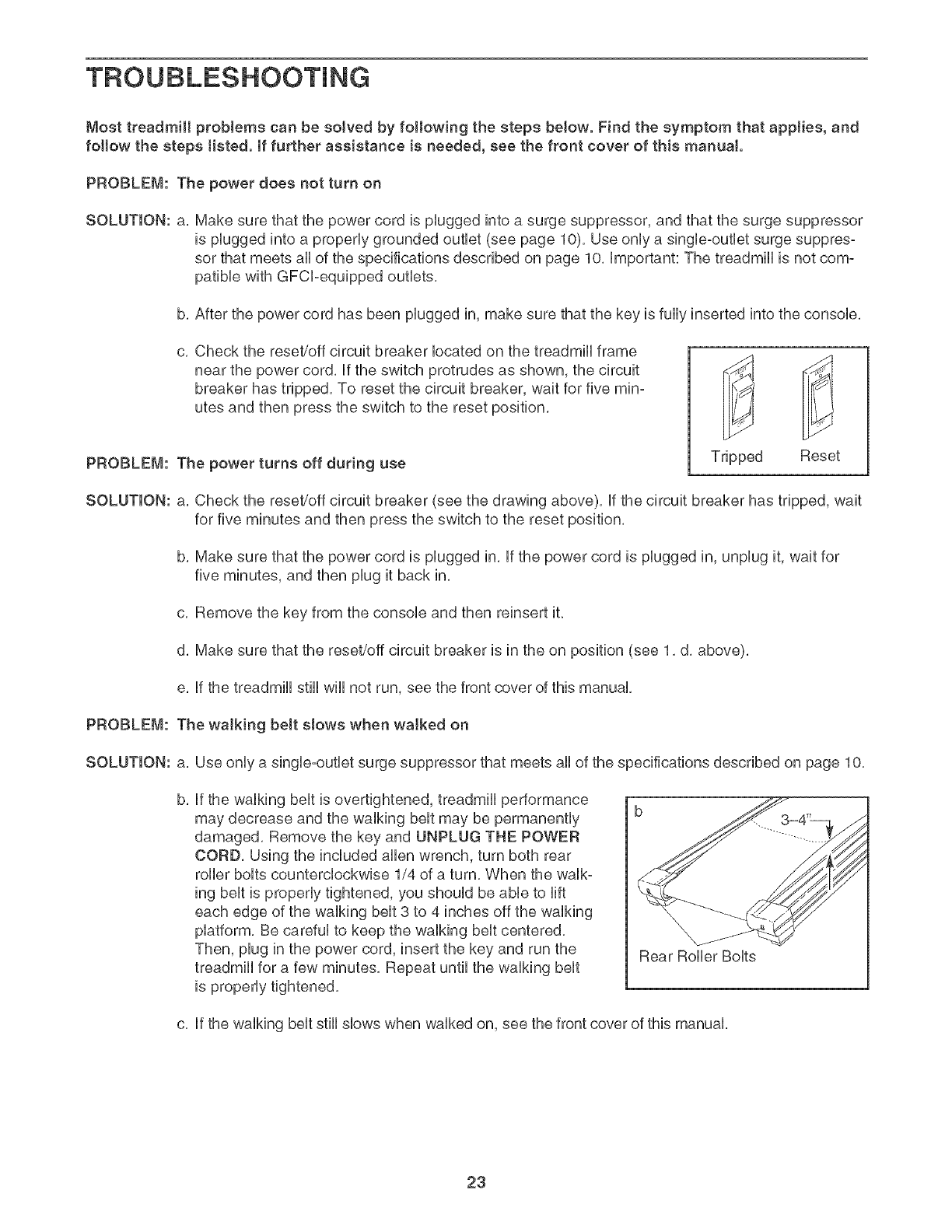
C, Check the reset/off circuit breaker located on the treadmill frame
near the power cord. if the switch protrudes as shown, the circuit
breaker has tripped. To reset the circuit breaker, wait for five min-
utes and then press the switch to the reset position.
PROBLEM: The power turns off during use Tripped Reset
SOLUTmON: a. Check the reset/off circuit breaker (see the drawing above), if the circuit breaker has tripped, wait
for five minutes and then press the switch to the reset position.
b. Make sure that the power cord is plugged in. if the power cord is plugged in, unplug it, wait for
five minutes, and then plug it back in.
c. Remove the key from the console and then reinsert it.
d. Make sure that the reset/off circuit breaker is in the on position (see 1. d. above).
e. if the treadmill still wiii not run, see the front cover of this manual.
PROBLEM: The walking belt slows when walked on
SOLUTION: a. Use only a single-outlet surge suppressor that meets all of the specifications described on page 10.
b, if the walking belt is overtightened, treadmill performance
may decrease and the walking belt may be permanently
damaged. Remove the key and UNPLUG THE POWER
CORD. Using the included allen wrench, turn both rear
roller bolts counterclockwise 1/4 of a turn. When the walk°
ing belt is properly tightened, you should be able to lift
each edge of the walking belt 3 to 4 inches off the walking
platform. Be careful to keep the walking belt centered.
Then, plug in the power cord, insert the key and run the
treadmill for a few minutes. Repeat until the walking belt
is properly tightened.
Rear Roller Bolts
c. if the walking belt still slows when walked on, see the front cover of this manual.
23
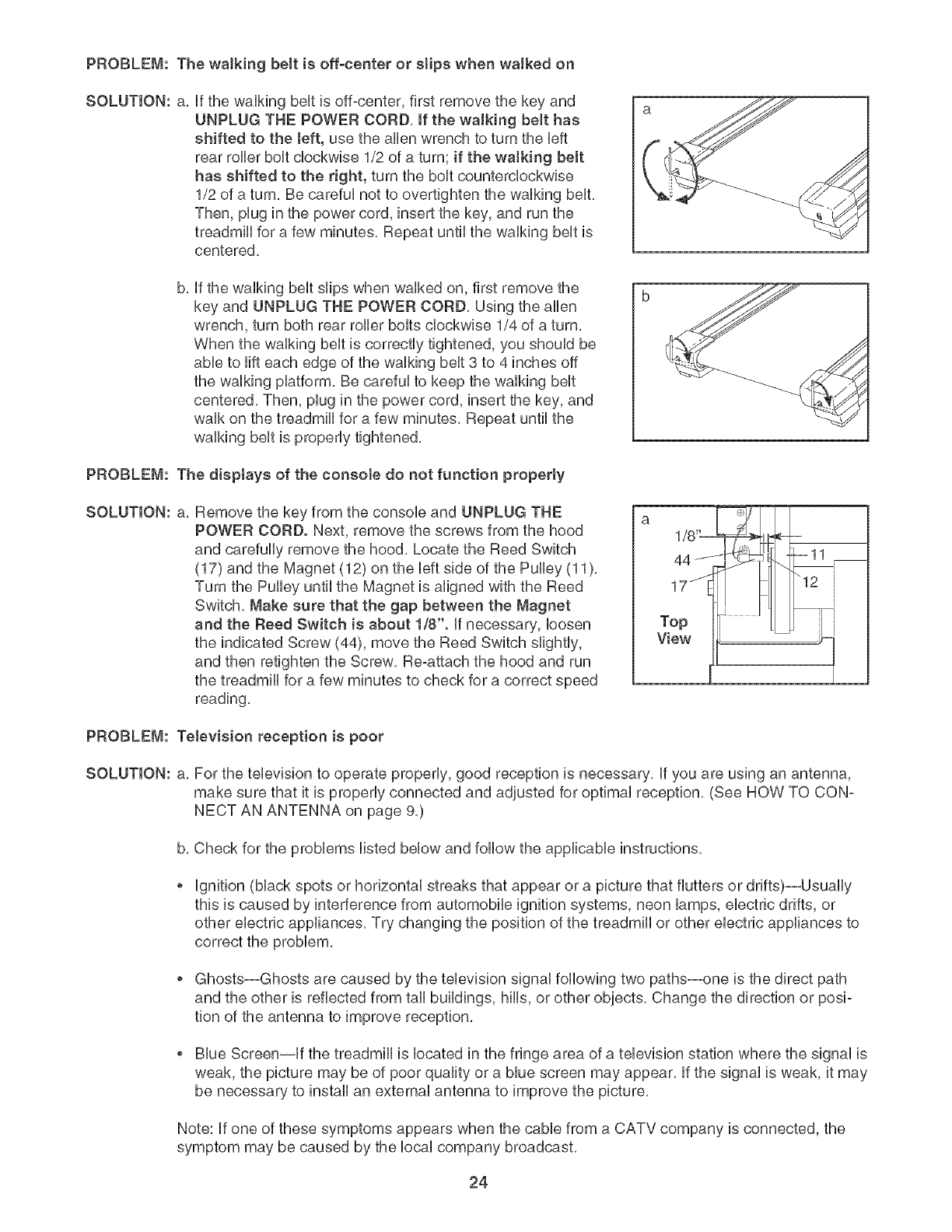
PROBLEM: The walking belt is off-center or stips when walked on
SOLUTION: a, if the waIMng belt is off-center, first remove the key and
UNPLUG THE POWER CORD, If the walking belt has
shifted to the teft, use the allen wrench to turn the Heft
rear roller boit cHockwbe 1/2 of a turn; if the walking belt
has shifted to the right, turn the boit countercHockwbe
1/2 of a turn, Be carefui not to overtighten the waiking bent,
Then, plug in the power cord, insert the key, and run the
treadmHi for a few minutes, Repeat until the waiMng bent is
centered,
b, if the walking belt sfips when walked on, first remove the
key and UNPLUG THE POWER CORD, Using the allen
wrench, turn both rear roller bolts clockwise 1/4 of a turn,
When the walking belt is correctly tightened, you should be
abie to rift each edge of the waiking bent 3 to 4 inches off
the waiking piatform, Be carefui to keep the waiking bent
centered, Then, piug in the power cord, insert the key, and
waik on the treadmili for a few minutes, Repeat untii the
waiking bent is properiy tightened,
PROBLEM: The disptays of the consote do not function properly
SOLUTION: a, Remove the key from the console and UNPLUG THE
POWER CORD. Next, remove the screws from the hood
and carefuliy remove the hood, Locate the Reed Switch
(17) and the Magnet (12) on the Heftside of the Pulley (11),
Turn the Pulley untii the Magnet is aligned with the Reed
Switch, Make sure that the gap between the Magnet
and the Reed Switch is about 1/8". if necessary, ioosen
the indicated Screw (44), move the Reed Switch slightly,
and then retighten the Screw, Re-attach the hood and run
the treadmill for a few minutes to check for a correct speed
reading,
1/8 "[
44-'-
17 j
Top
View
PROBLEM: Television reception is poor
SOLUTION: a, For the television to operate properly, good reception is necessary, if you are using an antenna,
make sure that it is properly connected and adjusted for optimal reception, (See HOW TO CON-
NECT AN ANTENNA on page 9,)
b, Check for the problems listed below and follow the applicable instructions,
ignition (black spots or horizontal streaks that appear or a picture that flutters or drifts)--Usually
this is caused by interference from automobile ignition systems, neon lamps, electric drifts, or
other electric appliances, Try changing the position of the treadmill or other electric appliances to
correct the problem,
Ghosts--Ghosts are caused by the television signal following two paths--one is the direct path
and the other is reflected from tall buildings, hills, or other objects, Change the direction or posi-
tion of the antenna to improve reception,
Blue Screen--if the treadmill is located in the fringe area of a television station where the signal is
weak, the picture may be of poor quality or a blue screen may appear, if the signal is weak, it may
be necessary to install an external antenna to improve the picture,
Note: if one of these symptoms appears when the cable from a CATV company is connected, the
symptom may be caused by the local company broadcast,
24
EXERCISE GUiDELiNES
WARNING: Beforebeginningth a
or any exercise program, consult your phyei=
cian. This is especially important for individu-
als over the age of 35 or individuals with pre=
existing health problems.
The pulse sensor is not a medical device.
Various factors, incJuding the user's move-
ment, may affect the accuracy of heart rate
readings. The pulse sensor is intended only
as an exercise aid in determining heart rate
trends in general
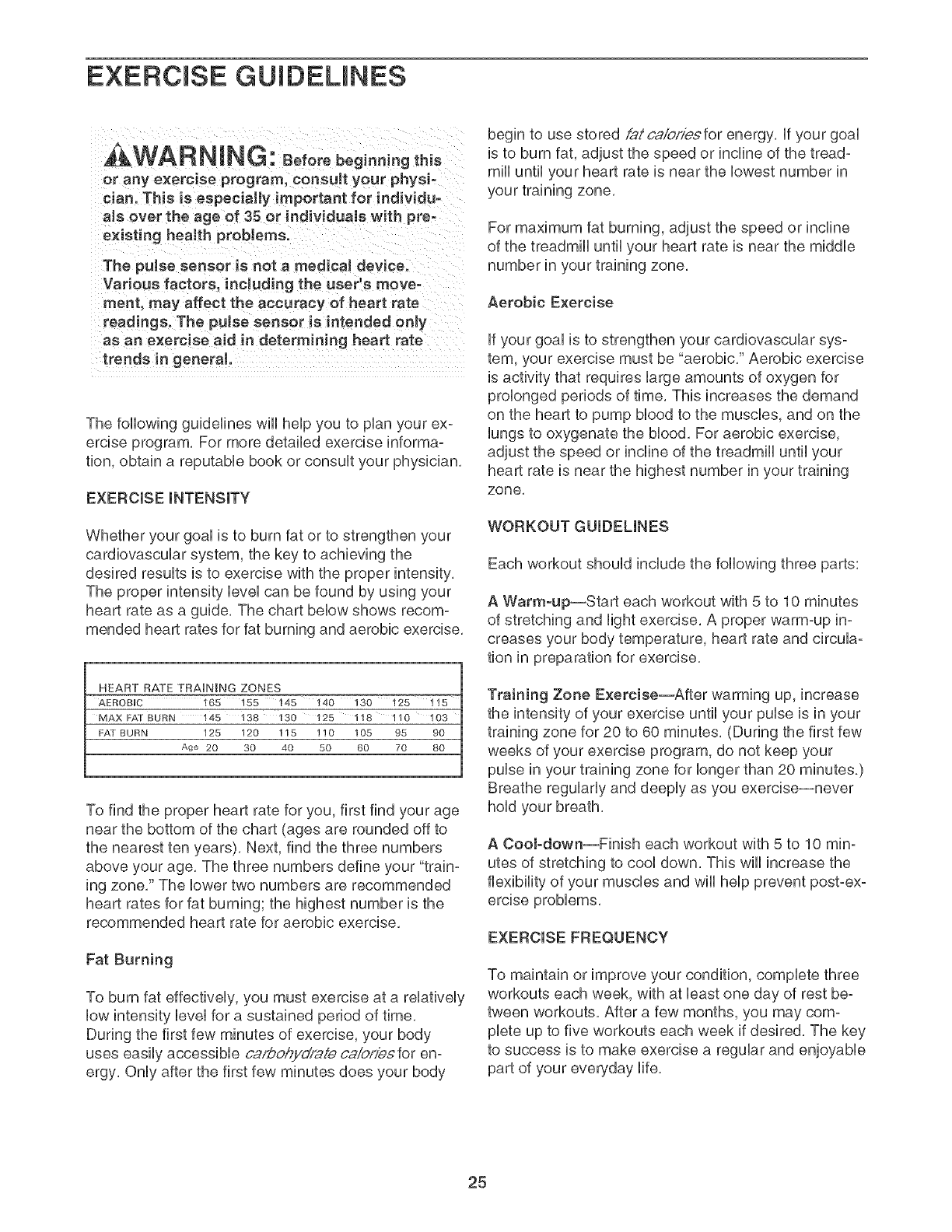
The following guidelines wiii help you to plan your ex=
ercise program, For more detailed exercise informa=
tion, obtain a reputable book or consult your physician,
EXERCISE iNTENSiTY
Whether your goal is to burn fat or to strengthen your
cardiovascular system, the key to achieving the
desired results is to exercise with the proper
The proper intensity level san be found by using your
heart rate as a guide, The chart below shows recom-
mended heart rates for fat burning and aerobic exercise,
HEART RATE TRAINING ZONES
AEROBUC 165 155 145 140 130 125
MAX I:A] BURN 145 138 130 125 118 110 I03
FAT BURN 125 120 115 110 105 95 90
Age 20 30 40 50 60 70 80
To find the proper heart rate for you, first find your age
near the bottom of the chart (ages are rounded off to
the nearest ten years), Next, find the three numbers
above your age, The three numbers define your "train=
ing zone," The lower two numbers are recommended
heart rates for fat burning; the highest number is the
recommended heart rate for aerobic exercise,
Fat Burning
To burn fat effectively, you must exercise at a relatively
low intensity level for a sustained period of time,
During the first few minutes of exercise, your body
uses easily accessible ca,@ohydraie caiof/esfor en:
ergy, Only after the first few minutes does your body
begin to use stored @tca/b/s/esfor energy, if your goal
is to burn fat, adjust the speed or incline of the tread-
mill until your heart rate is near the lowest number in
your training zone,
For maximum fat burning, adjust the speed or incline
of the treadmill until your heart rate is near the middle
number in your training zone,
Aerobic Exercise
if your goal is to strengthen your cardiovascular sys=
tern, your exercise must be "aerobic," Aerobic exercise
is activity that requires large amounts of oxygen for
prolonged periods of time, This increases the demand
on the heart to pump blood to the muscles, and on the
lungs to oxygenate the blood, For aerobic exercise,
adjust the speed or incline of the treadmill until your
heart rate is near the highest number in your training
zone,
WORKOUT GUIDELINES
Each workout should include the following three parts:
A Warm-up--Start each workout with 5 to 10 minutes
of stretching and light exercise, A proper warm-up in-
creases your body temperature, heart rate and circula-
tion in preparation for exercise,
Training Zone Exercise--After warming up, increase
the intensity of your exercise until your pulse is in your
training zone for 20 to 60 minutes, (During the first few
weeks of your exercise program, do not keep your
pubs in your training zone for longer than 20 minutes)
Breathe regularly and deeply as you exercise--never
hold your breath,
A CooJ-down--Finish each workout with 5 to 10 min:
utes of stretching to cool down, This will increase the
flexibility of your muscles and will help prevent post-ex-
EXERCISE FREQUENCY
To maintain or improve your condition, complete three
workouts each week, with at bast one day of rest be-
tween workouts, After a few months, you may com-
plete up to five workouts each week if desired, The key
to success is to make exercise a regular and enjoyable
part of your everyday life,
25

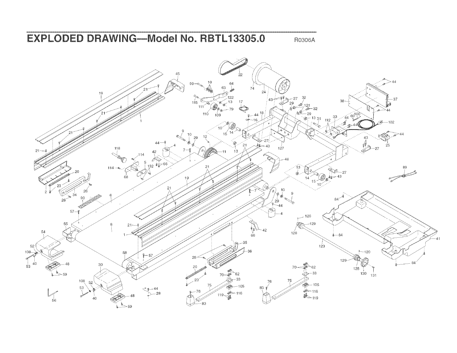
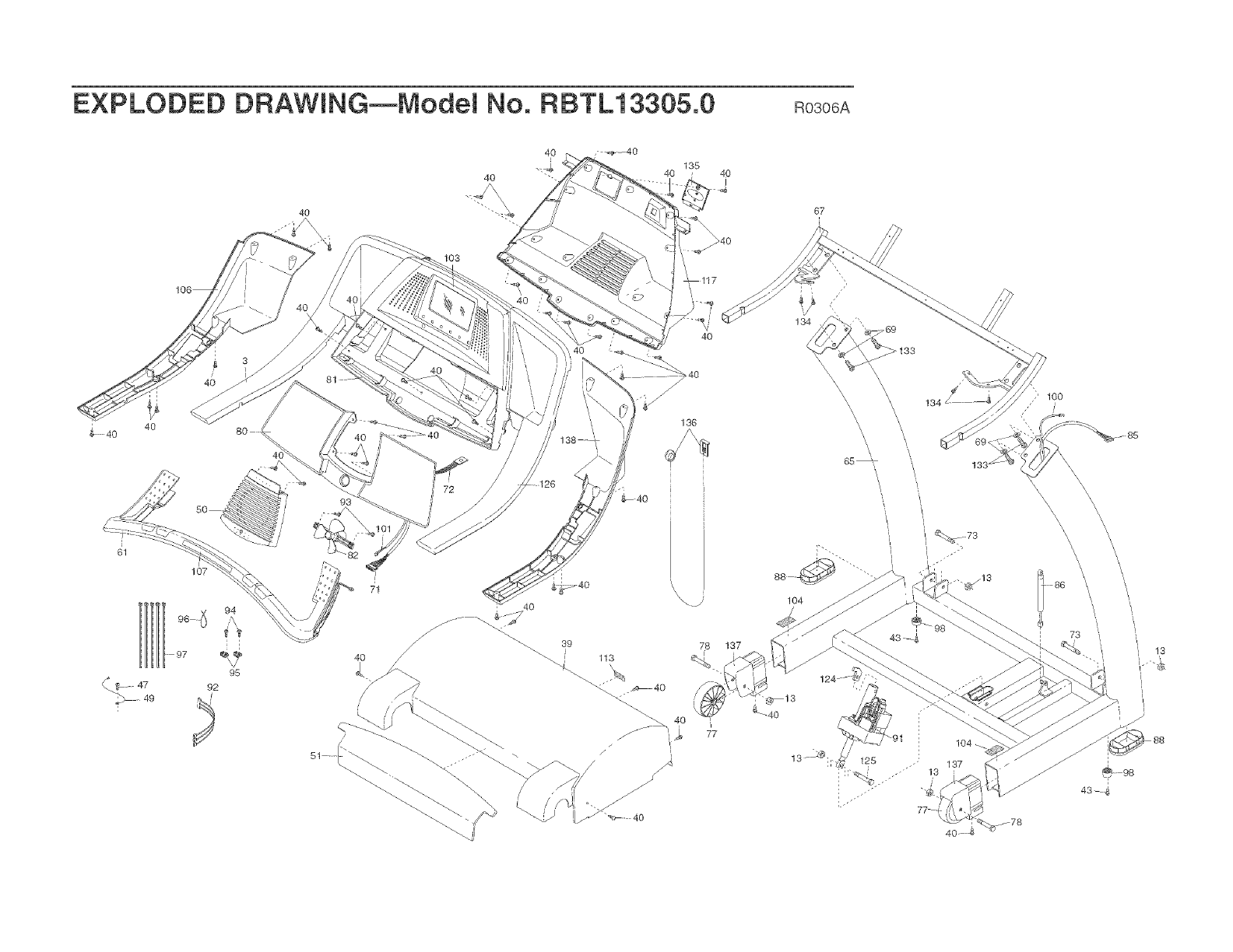
PART LiST--Model No. RBTL13305.0 Ro3o6A
To Uocate the parts Hsted beUow,see the EXPLODED DRAWUNG attached in the center of this manual
Key No. Qty. Description Key No. Qty. Description
1 2 Foot Rail 51
2 1 Left Outside Housing 52
3 1 Left Handgnp, Top 53
4 4 UsoUator 54
5 1 Latch Housing Cover 55
6 1 Hatform 56
7 2 WaUMng Hatform Screw 57
8 1 WaUMng BeUt 58
9 2 Frame Pivot BoUt 59
10 4 Frame Pivot Washer 60
11 1 61
12 1 Magnet 62
13 9 Front Roller Nut/Front WheeUNut 63
14 2 Spacer Insert 64
15 2 Frame Pivot Spacer 65
16 1 Reed Switch CHp 66
17 1 Reed Switch 67
18 1 Lift Frame 68
19 2 Foot Rail Insert 69
20 2 Gear Rack 70
21 14 Foot Rail Screw 71
22 1 Motor BeUt 72
23 4 Gear Rack Screw 73
24 1 Drive Motor 74
25 1 Transformer 75
26 4 Cushion Adj, Housing Screw 76
27 4 Hood Bracket 77
28 1 Ground Wire 78
29 4 Star Washer 79
30 1 Right Rear Endcap 80
31 1 Lift Motor BoUt 81
32 2 Motor BoUt 82
33 2 Cushion Hate 83
34 1 Left Unside Housing 84
35 1 Right Inside Housing 85
36 1 Right Outside Housing 86
37 1 Controller 87
38 1 Controller Bracket 88
39 1 Motor Hood 89
40 48 3/4" Screw 90
41 1 Motor Belly Pan 91
42 2 Belt Guide 92
43 6 3/4" Tek Screw 93
44 12 Electronics Screw 94
45 1 Left Front Endcap 95
46 1 Right Front Endcap 96
47 1 Ground Screw 97
48 2 Rear Foot 98
49 1 Console Ground Wire 99
50 1 Fan Housing 100
1
2
2
1
1
1
2
1
4
2
1
4
1
1
1
4
1
1
4
4
1
1
2
1
2
2
2
2
1
1
1
1
2
4
1
1
2
2
1
1
1
1
2
2
2
1
5
2
1
1
Hood Cover
Roller Adj, Washer
Rear Roller Adjustment Bolt
Left Rear Endcap
Frame
Allen Wrench
Rear Platform Screw
Rear Roller
Foot Screw
Cable Nut
Pulse Bar
Spring Nut
Idler Arm
Idler Spring
Upright/Base
Belt Guide Screw
Console Frame
Latch Housing
Console Washer
Spring Washer
Console Wire Harness
iFF,com Wire
Incline Pivot Bolt
Flywheel
Spring
Spring Pad Screw
Front Wheel
Wheel Bolt
Pulley Nut
Console
Console Base
Fan
Spring Pad
Belly Pan Screw
Upright Wire Harness
Shock
Spring Plate Spacer
Upright Endcap
Filter Wire
Latch Warning Decal
Incline Motor
Motor Controller Wire
Fan Screw
Tie Holder Screw
Tie Holder
Tie
8" Cable Tie
Base Pad
Idler Arm Bolt
Upright TV Cable
26

Key No. Qty. Description
101 1 Pulse Wire
102 1 Power Cord Assembly
103 1 TV Consob
104 2 Warning Decal
105 2 Spring Hate
106 1 Left Handgrip, Bottom
107 1 Warning Decal, Pulse Bar
108 2 Rear Rolbr Star Washer
109 1 Pulby Washer
110 1 Idbr Pulby
111 1 Pulby Spacer
112 2 Outbt Bracket Star Washer
113 1 Static Decal
114 2 1/2" Tek Screw
115 1 Idbr Pulby Bolt
116 4 Spring Washer
117 1 Consob Back
118 1 Latch Assembly
119 4 Spring Bolt
120 2 Cushion Adj. Pin
121 2 Motor Bushing
122 1 Idbr Arm Nylon Washer
123 1 Cushion Adj. Rod
124 1 Incline Bracket
125 1 Incline Motor Bolt, Bottom
Key No. Qty. Description
126 1 Right Handgrip, Top
127 1 Motor Isolator Hate
128 2 Cushion Adj. Gear
129 2 Cushion Adj. Wheel
130 1 Cushion Adj. Knob
131 1 Cushion Adj. Screw
132 2 1/2" Screw
133 4 1" Consob Bolt
134 4 Pulse Bar Screw
135 1 Access Door
136 1 Key/Clip
137 2 Wheel Housing
138 1 Right Handgrip, Bottom
# 1 8" Blue Wire, 2 F
# 1 4" Blue Wire, M/F
# 1 4" Blue Wire, 2 F
# 1 Blue Wire, M/F
# 1 12" Green Wire, F/Ring
# 1 8" Green Wire, 2 Ring
# 1 14" White Wire, 2 F
# 1 4" Black Wire, 2 F
# 1 User's Manual
# These parts are not illustrated
Specifications are subject to change without notice.
ORDERING REPLACEMENT PARTS
To order replacement parts, see the front cover of this manual. When ordering parts, please be prepared to give
the following information:
*the MODEL NUMBER OF THE PRODUCT (RBTL13305.0)
*the NAME OF THE PRODUCT (REEBOK VISTA treadmill)
*the SERIAL NUMBER of the product (see the front cover of this manual)
*the KEY NUMBER and DESCRiPTiON of the part(s) (see the PART LiST on pages 26 and 27)
27
EXPLODED DF{AWHNG--ModeM No. RBTL13305.0 Roso6A
2 g/ 26
34
26 _ 90
55
54
82i
83
58
!9
I
4O
21
22
lO
17
©
!!0 109 2_ 44 1
_-18
21
19
/
127 28
89
//
EXPLODED DRAWHNG--ModeM No. RBTL13305.0 Roso6A
40
40
40
135
4O 40
I
67
40
97
107
92
94
/\
!03
40
77
] • j'
!34
\
\
,/}' 100

LiMiTED WARRANTY
WHAT IS COVERED--The entire REEBOK VISTA ("Product") is warranted to be free of all defects in material and work_
manship.
WHO IS COVERED--The original purchaser or any person receiving the Product as a gift from the original purchaser.
HOW LONG IS IT COVERED--ICON Health & Fitness, Inc. ("ICON"), warrants the drive motor for twenty years after the
date of purchase. Parts and labor are covered for one year after the date of purchase.
WHAT WE DO TO CORRECT COVERED DEFECTS--We will ship to you, without charge, any replacement part or com-
ponent, providing the repairs are authorized by ICON first and are performed by an ICON trained and authorized service
provider, or, at our option, we will replace the Product.
WHAT IS NOT COVERED--Any failures or damage caused by unauthorized service, misuse, accident, negligence, im-
proper assembly or installation, alterations, modifications without our written authorization or by failure on your part to use,
operate, and maintain as set out in your User's Manual ("Manuar').
WHAT YOU MUST DO--Always retain proof of purchase, such as your bill of sale; store, operate, and maintain the
Product as specified in the Manual; notify our Customer Service Department of any defect within 10 days after discovery of
the defect; as instructed, return any defected part for replacement or, if necessary, the entire product, for repair.
USER'S MANUAL--It is VERY IMPORTANT THAT YOU READ THE MANUAL before operating the Product. Remember
to do the periodic maintenance requirements specified in the Manual to assure proper operation and your continued satis-
faction.
HOW TO GET PARTS AND SERVICE--Simply call our Customer Service Department at 1-877-994-4999 and tell them
your name and address and the serial number of your Product. They will tell you how to get a part replaced, or if neces-
sary, arrange for service where your Product is located or advise you how to ship the Product for service. Before shipping,
always obtain a Return Authorization Number (RA No.) from our Customer Service Department; securely pack your
Product (save the original shipping carton if possible); put the RA No. on the outside of the carton and insure the product.
Include a letter explaining the product or problem and a copy of your proof of purchase if you believe the service is covered
by warranty.
ICON is not responsible or liable for indirect, special or consequential damages arising out of or in connection with the use
or performance of the product or damages with respect to any economic loss, loss of property, loss of revenues or profits,
loss of en}oyment or use, costs of removal, installation or other consequential damages of whatsoever nature. Some states
do not allow the exclusion or limitation of incidental or consequential damages. Accordingly, the above limitation may not
apply to you.
The warranty extended hereunder is in lieu of any and all other warranties and any implied warranties of merchantability or
fitness for a particular purpose is limited in its scope and duration to the terms set forth herein. Some states do net allow
limitations on how long an implied warranty lasts. Accordingly, the above limitation may not apply to you.
No one is authorized to change, modify or extend the terms of this limited warranty.
This warranty gives you specific legal rights and you may have other rights which vary from state to state.
iCON HEALTH & FmTNESS, INC., 1500 S. 1000 W., LOGAN, UT 84321o9813
Part No, 232546 R0306A Printed in USA © 2006 iCON IP, Inc,
