RELM Communications RPU499A UHF Land Mobile Radio User Manual s
RELM Communications Inc UHF Land Mobile Radio s
users manual
2
Preface
Scope
This manual is intended for use by qualified technicians familiar with similar types of communication equipment. It
contains all service information and data required for the equipment.
Caution
The following precautions are recommended for personnel safety:
DO NOT transmit until all RF connectors are verified secure and all connectors are properly terminated.
SHUT OFF the power and DO NOT operate this equipment near electrical blasting caps or in a potential explosive
atmosphere.
This equipment should be serviced by qualified technicians only.
3
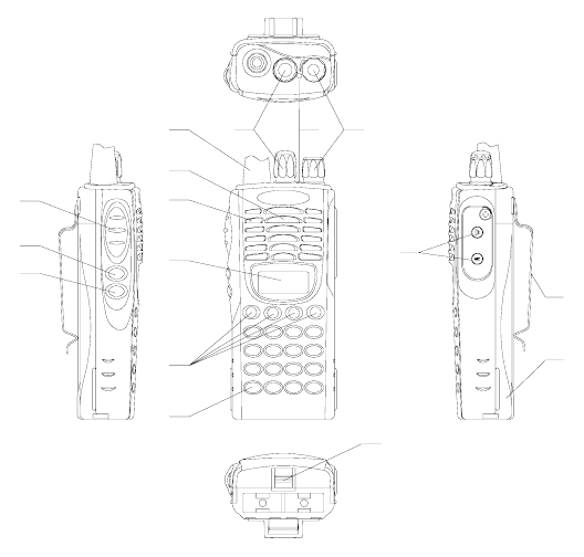
Brief Introduction
(1) ANTENNA
(2) CHANNEL SELECTOR KNOB
Used to select channel and squelch level. In addition, it can be programmed by the dealer to
delete undesired channels from scan list or to select a CTCSS frequency.
(3) LED INDICATOR
Is red when transmitting
Is green when receiving
Flashes red when the battery voltage is low and approaching the cut-off point
Flashes orange, when the radio receives proper DTMF or Two Tone decode signals.
(4) ON-OFF/VOLUME KNOB
Rotate the volume control knob clockwise to turn the unit “on” and fully counter clockwise
to turn the unit “off”. Increase or decrease volume by adjusting the volume control
accordingly.
(5) SPEAKER
(6) MICROPHONE
(7) LCD
Used to display channel and operation status.
(8) (●,○,■,□) PROGRAMMABLE SOFT KEYS
Used to enable auxiliary functions. Press each key to enable its corresponding function.
(9) KEYPAD
Used to enter, store or send DTMF codes.
9
8
16
7
5
6
12
11
10
15
234
1
13
14
4
(10) PTT BUTTON
Used to switch between transmit and receive mode.
(11) LAMP BUTTON
Used to turn on/off the LCD backlight. Press the [LAMP] button, the backlight will
illuminate for about 5 seconds and then automatically turn off. Press any key other than
[LAMP] button, the timer will retime. If you press the [LAMP] button, the backlight will
light off.
(12) MONI BUTTON
Used to monitor the selected channels.
(13) EXTERNAL SPEAKER-MICROPHONE JACK
Used to connect with external speaker-microphone, programming cable, or cloning cable.
(14) BELT CLIP
(15) BATTERY
(16) BATTERY LATCH
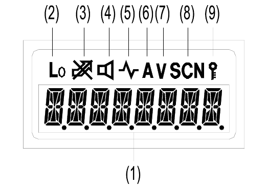
LCD
(1) Displays the selected channel number, channel frequency, channel label, squelch level or DTMF
code. When selective call is enabled, messages received are also displayed here.
Note: The “soft keys” can be programmed to toggle between display modes.
Channel Number– Displays channel number. Factory default.
Channel Frequency– Displays the channel frequency.
Channel Label– Displays characters of the channel label (up to 16 alphanumeric characters can be
programmed. Any label over 8 characters will scroll across the display).
(2) Appears when Low Power is selected.
(3) Appears when selected channel is busy.
(4) Appears when MONI button is pressed to disable CTCSS, CDCSS, DTMF or 2-Tone.
(5) Appears when MONI button is pressed to switch the speaker on.
(6) Appears when current channel is in the scan list. Radio only scans channels in scan list.
(7) Appears when enter number during channel label programming. Appears when CDCSS decoder
is reversed in destination set mode.
(8) Appears in scan mode.
5
(9) Appears when keypad lock is on.
6
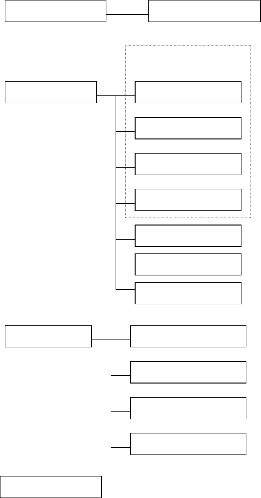
Radio Modes
1. Frame of Radio Modes
Select the function you want from the modes and make the necessary settings.
Conventional mode USER MODE
Alignment Mode
TEST MODE LCD Full Screen mode
Destination Set Mode
Frequency Display mode
Function Set Mode
Channel Set Mode
DEALER MODE
DTMF Set Mode
Wired Clone Mode
Wireless Clone Mode
All Reset
Self-Programming mode
N
ew Function Set
Mode
PC MODE

7
2. Description of Mode Functions
3. Keypad Entry for Mode Startup
MODE FUNCTION
USER MODE Conventional mode
DEALER MODE
Dealer set the below modes:
Function set mode, DTMF set mode, Channel set mode, Wired clone mode, Wireless clone
mode, All Reset
Self Programming
(FUNCTION SET MODE)
The dealer set the following functions ON/OFF according to the user operating needs.
1.Monitor 2.Scan 3.Dial 4. Talk around 5.Low 6.Priority 7.Priority Channel 8.Look Back A
9.Look Back B 10.Revert Channel 11.TX Dwell time 12.Dropout Delay Time 13.Time out
Timer 14.Tramsmit Warning 15.TOT Rekey Time 16.TOT Reset Time 17.Squelch Level
18.BEEP 19.Signalling 20.Battery Save 21.Selectable CTCSS 22.DELETE/ADD
23.Dealer Mode-Test Mode
Self Programming
(DTMF SET MODE)
The dealer set the following functions ON/OFF according to the user operating needs.
24.Digit Time 25.Inter Digit Time 26.First Digit Time 27.Rise Time 28.Rise Time with
CTCSS 29.PTT ID 30.Dial ID 31.Connect ID 32.Disconnect ID 33. NO. of DTMF key
34.DTMF Hold Time 35.Store & Send 36.D key Assignment 37.DTMF Signaling
38.Intermediate Code 39.Group Code 40 SQ. Auto Reset Time
41.Call Alert/ Transpond
Self Programming
(CHANNEL SET MODE)
The dealers use this mode to set channel frequencies and signaling according to the user
operating needs.
1.Channel Selection 2.RX Frequency 3.RX Signaling 4.TX Frequency 5.TX Signaling
6.DTMF/2-Tone signaling 7.PTT ID Enable 8.Scan DEL/ADD 9.Busy Channel Lockout
10.Clock Frequency Shift 11.TX Power 12.Wide/narrow Band
13. ID Code/RX 2-Tone 14. TX 2-Tone 15. Channel Label
Self Programming
(NEW FUNCTION MODE)
45.group tone 46. group tone duration 47. channel label size
48. programmable key 1 [●] 49. programmable key 2 [○]
50. programmable key 3 [■] 51. programmable key 4 [□]
WIRED CLONE MODE In this mode data is copied from one radio to another through a cable.
WIRELESS CLONE MODE In this mode data is copied from one radio to another without cable by means of the DTMF
signal.
ALL RESET In this mode transmit/receive frequencies of each channel and function settings are
initialized.
MENU MODE This mode is used to enter the following setting options.
ADJUSTMENT
MODE
This mode is for alignment of radio operation.
FREQUENCY
TEST MODE
This mode is for checking the frequencies and repairing the radio.
ADJUSTMENT
DATA CLONE
MODE
This mode is used to clone adjustment data from one radio to another.
LCD FULL SCREEN
MODE
All characters and signs on the LCD are displayed.
TEST
MODE
DESTINATION SET
MODE
This mode sets radio destination.

8
Prohibit entering dealer mode and test mode
Dealer mode and test mode can be prohibited by programming to prevent users from changing the parameters with self-
programming feature or with external programmer.
Cancel the Prohibit
Short the dealer mode control point and the test mode control point and then the prohibit will be cancelled at
POWER-ON. Or use the programming software to cancel.
Note:
The dealer mode control point and the test mode control point locate over LCD and marked with SELF.
DEALER MODE
Self-Programming (Function Setting)
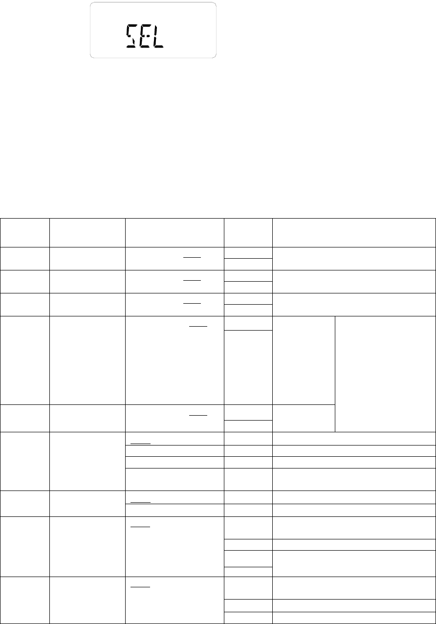
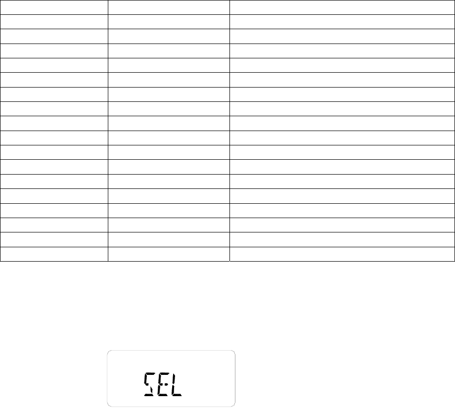
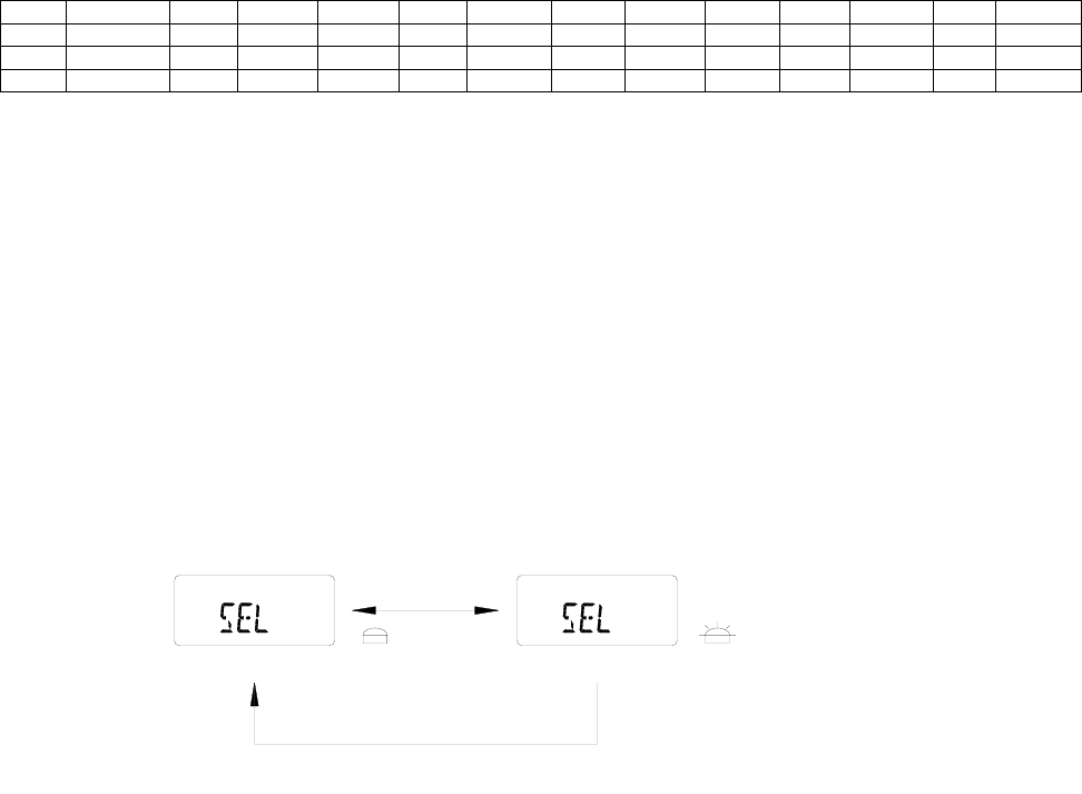
1. Turn on the power while pressing [LAMP] and [○] key, in 2 seconds the radio enters the dealer mode, and “SEL”
appears on LCD.
Note: please refer to the notes of self-programming mode.
2. In dealer mode, press [●] key to enter function set mode.
3. Use Channel Selector knob to set functions ON or OFF or to select the setting.
4. After a function is set, press [PTT] to store the setting and the menu goes to the next function option.
MODE Key Remarks
USER
MODE Conventional Mode POWER ON Turn on the power to enter Conventional Mode
Function Set Mode
While holding down [LAMP] and
[○] key simultaneously, turn on the
power (in 2 seconds)
Press [●] key to enter Function Set Mode.
DTMF Set Mode As above Press [○] key to enter DTMF Set Mode.
Channel Set Mode As above Press [■] key to enter Channel Set Mode.
New function set
mode As above Press [□] key to enter New Function Set Mode.
Wired Clone Mode As above Press [LAMP] to enter Wired Clone Mode.
Wireless Clone
Mode As above Press [MONI] to enter Wireless Clone Mode.
DEALER
MODE
All Reset As above Press [□] key and [PTT] simultaneously.
Menu Mode
While holding down [LAMP] and
[■] key simultaneously, turn on the
power (in 2 seconds).
Press [□] key to enter test mode and [■] key to
return to Menu Mode.
Adjustment Mode Select “ADJUST” in menu mode.
Frequency Test
Mode
Select “FREQ TST” in menu mode.
Adjustment Data
Clone Mode Select “TUNE CLN” in menu mode.
LCD Full Screen
Mode Select “FULL LCD” in menu mode.
TEST
MODE
Destination Set
Mode Select “DEST SET” in menu mode.
Press [□] key to enter the mode and [■] key to exit.

9
5. Press [●] key to return to Dealer Mode from current option, and the current data shown on the display will not be
stored.
6. Press [PTT] to store current function setting and a beep will sound to confirm the action.
7. END appears when settings in function mode are completed.
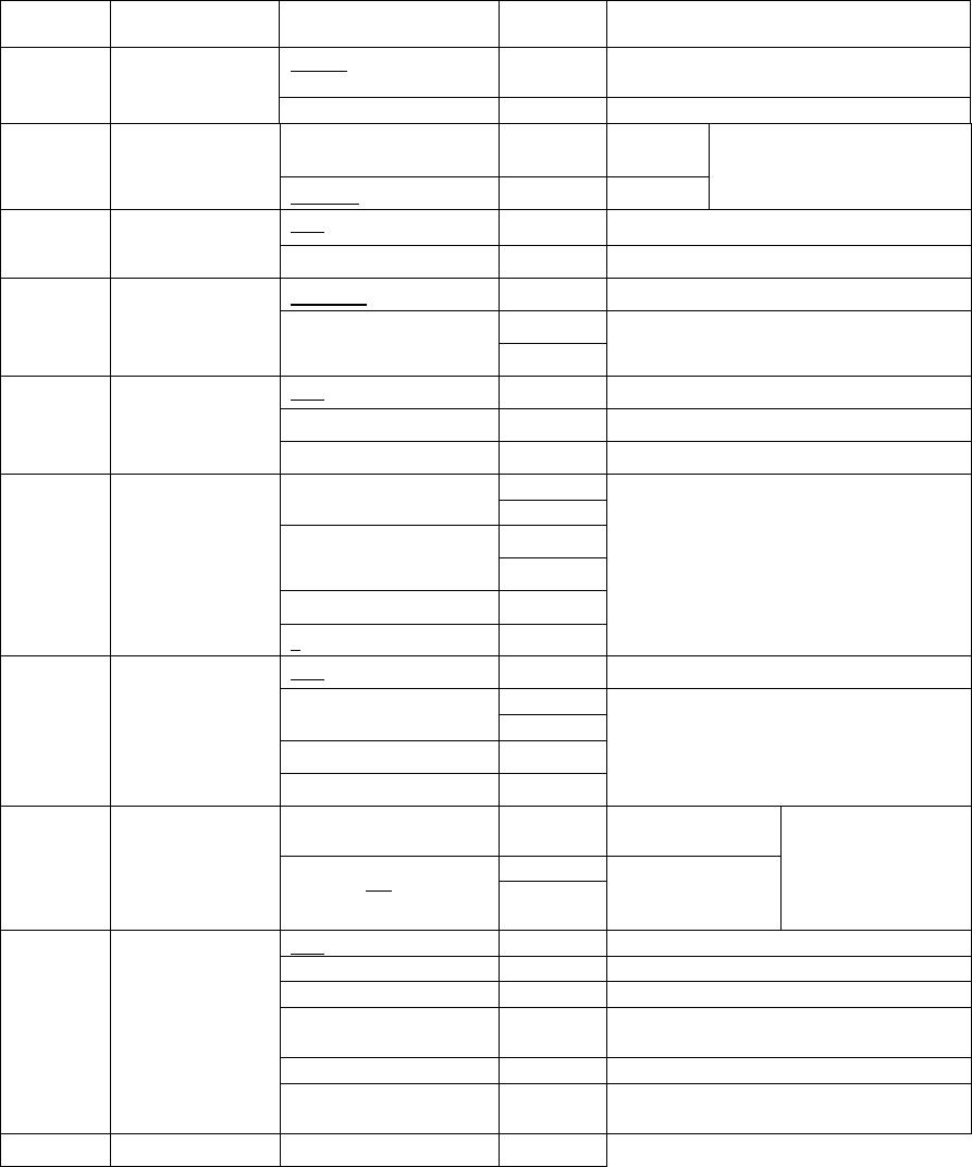
Function
No.
Function
Name
Settings (Defaults are
underlined) Display Remarks
OFF MONI OFF Invalid
Monitor Momentary MONI 1 Signaling squelch is temporarily disabled while [MONI]
button is held down.
Monitor Lock MONI 2
Signaling squelch is temporarily disabled while [MONI]
button is pressed. Each time press can toggle between
squelch disable and enable.
1 MONITOR
SQ OFF
Momentary MONI 3 Squelch is disabled while [MONI] button is held down.
OFF SCAN OFF Invalid
CO SCAN CO “Carrier Operated” function
2 SCAN
TO SCAN TO “Time Operated” function
Disable DIAL OFF Disables the [DIAL] key.
3 [DIAL] Enable DIAL ON Enables the [DIAL] key.
Disable TARE OFF Invalid
Talk Around TARE TA “Talk around” function is enabled
4 TALK
AROUND Reverse TARE RE “ Frequency Reverse” function is enabled
Disable LO OFF Disables [LO] key.
5 [LO] Enable LO ON Enables [LO] key.
OFF PRIO OFF NO priority setting
Fixed PRIO FIX Fixed priority channel
6 PRIORITY
Selected PRIO SEL Variable priority channel
PRICH 1
7 PRIORITY
CHANNEL
1 ~ 99 1
PRICH 99
Priority channel
(Only valid when “fixed priority” is enabled)
LBA 300
8 LOOK BACK
A
0.3s ~1.5s 0.5s
(0.1s/1STEP) LBA 1500
The period time between radio back scanning a priority
channel from a normal channel when there is no activity
on priority channel
9 LOOK BACK
B
0.5s ~ 5.0s 2.0s
(0.5s/1STEP) LBB 500
The period time between radio back scanning a priority
channel from a normal channel when there is activity on
priority channel but not matching its signaling.
Selected REV SEL Channel where scan starts.
Last Call REV LSTC During scanning, it’s the latest channel at pause; during
scan stopping, it’s the channel stopped; if scan never
stops, it’s the start channel.
Last Used REV LSTU During scanning, it’s the latest transmit channel; during
scan stopping, it’s the channel stopped; if scan never
stops, it’s the start channel.
10 REVERT
CHANNEL
Selected + Talk Back SEL TALK During scanning, it’s the start channel; during scan
stopping, it’s the channel stopped.
Priority REV PRIO Priority channel
Priority + Talk Back PRI TALK During scanning, it’s the priority channel; when scan
stopping, it’s the channel stopped.
TSDT 0.5 Duration before scan restarts when it stops by
transmission.
11
TX-SCAN
DWELL
TIME
0.5s ~ 5.0s 3.0s
(0.5s/1STEP) TSDT 5.0
12 DROP OUT
DELAY TIME
0.5s ~ 5.0s 3.0s
(0.5s/1STEP) DODT 0.5 Duration before scan restarts when it stops by signal
input.
DODT 5.0

10
13 TIME OUT
TIMER
OFF 30s~300s 60s
(30s/1STEP) TOT OFF When OFF, in order to protect power amplifier, max. time
of continuous transmission is set as 10 minutes.
TOT 30
TOT 300
Maxi. time of continuous transmission
14 TOT ALERT
TIME
OFF 1 ~ 60
(10s/1STEP) TOTA OFF TOT off.
TOTA 1
TOTA 60
When this feature is enabled, the radio will call an
alert at the set time. Transmission will be prohibited
by TOT after this time.
15 TOT REKEY
TIME
OFF 1s ~ 60s OFF
(1s/1STEP) TOTK OFF Duration until transmission is allowed after radio
returning to receive mode by TOT.
TOTK 1
TOTK 60 Transmit prohibited until preset time elapses.
16 TOT RESET
TIME
OFF 1s ~15s OFF
(1s/1STEP) TOTS OFF TOT is immediately reset after transmission stops.
TOTS 1
TOTS 15
TOT won’t reset until preset time elapses, even if
transmission has stopped.
17 SQUELCH
LEVEL
0 ~9 5
(1s/1STEP) SQL 0 Squelch level is set higher (tighter), as the figure
increases.
SQL 9
18 BEEP NO BEEP OFF No beep tone
YES BEEP ON Beep tone sounds
19 SIGNALING AND SGNL AND Squelch is opened when both match.
OR SGNL OR Squelch is opened when either matches.
20 BATTERY
SAVE Disable BATT OFF No Battery Save function.
Enable BATT ON Battery Save function.
21 SELECTABLE
CTCSS Disable VQT OFF Prohibit Selectable CTCSS
Enable VQT ON Permit Selectable CTCSS
22
DELETE/
ADD
ENABLE
Disable SADD OFF Prohibit Delete/Add
Enable SADD ON Permit Delete/Add
23
DEALER
MODE/ TEST
MODE
ENABLE
Disable MODE OFF Prohibit dealer mode and test mode
Enable MODE ON Permit dealer mode and test mode
END END
When END is displayed, press [PTT] to return to Function Setting.
Note:
LOOK BACK: When radio is scanning a non-priority channel, the status of the priority channel will be detected
periodically. The time interval for this detecting is as the following:
A is period when there is no activity on the priority channel.
B is period when there is activity on the priority channel, however not matching its signaling.
Self-Programming (DTMF setting)
1. Turn on the power while pressing [LAMP] and [○] key simultaneously, and in 2 seconds the radio enters the dealer
mode.
11
2. In dealer mode, press [○] key to enter DTMF Set Mode.
3. Use Channel Selector knob and the 16 keys (0~9, *, #, A~D) to set DTMF function ON/OFF or select the setting.
4. Press [PTT] to store the selected settings, except functions 31 and 32, which are stored with the 16 keys, and the
menu goes to next function option.
5. Press
[○] key to return to Dealer Mode. The current setting displayed on LCD will not be stored.
6. Press [PTT] to store function settings and a Beep sounds to confirm the action.
7. END appears when all DTMF function settings are completed.
8. While pressing and holding [MONI], turn the channel selector to confirm the settings of each function option.
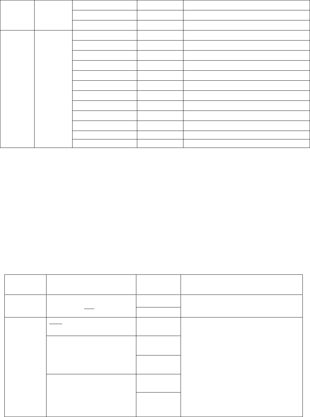
Function
No. Function Name Setting (Defaults are
underlined) Display Remarks
DIGT 50
24 DIGIT TIME 50ms ~ 200ms 50ms
(10ms/1STEP) DIGT 200
One digit transmitting time during DTMF
code transmission.
IDT 50
25 INTER DIGIT TIME 50ms ~ 200ms 50ms
(10ms/1STEP) IDT 200
Interval time between digits during DTMF
transmission.
FDT 50
26 FIRST DIGIT
TIME
50ms ~ 200ms 50ms
(10ms/1STEP) FDT 200
1st digit transmitting time during DTMF
transmission.
RISE 100
27 RISE TIME
100ms~1000ms 300ms
(50ms/1STEP) RISE1000
Set the time
between
unmodulated
carrier
transmission
and the DTMF
code
transmission
RTQT 100
28 RISE TIME WITH
CTCSS
100ms~1000ms 300ms
(50ms/1STEP) RTQT1000
Set time
Note: when DTMF
function is enabled
together with the Battery
Save and CTCSS functions
on, transmit delay time
should be over 300 ms.
OFF P.ID OFF Not send PTT ID.
Connect P.IDBEGIN Press [PTT], PTT ID is sent.
Disconnect P.ID END Release [PTT], PTT ID is sent.
29 PTT ID
Both P.ID BOTH Send PTT ID when both CONNECT and
DISCONNECT.
OFF D.ID OFF Prohibit Dial ID
30 DIAL ID ON D.ID ON Permit Dial ID
P.IDBEGIN Display about one second when entering this
setting.
-------- CONNECT ID is not set
0
31 CONNECT ID
Blank
0 × 1 ~ # × 16
FFFFFFFF
CONNECT ID is input (if more than 8, scroll
it)
P.ID END Display about one second when entering this
setting.
-------- Connect ID is not set.
32 DISCONNECT ID
Blank
0 × 1 ~ # × 16
0 CONNECT ID is in
p
ut
(
if more than 8, scroll
12
FFFFFFFF it)
12keys (0 ~ 9,*,#)
DTMFK 12
Disable [A] [B] [C][D] keys.
33 NO. of DTMF KEY
16keys (0 ~ 9,*,#,A ~ D) DTMFK 16 Enable [A] [B] [C][D] keys.
Disable
DHT OFF Do not
Hold
34 DTMF HOLD
TIME Enable DHT ON Hold
Function that continues
transmission for two seconds
even if manual DIAL key is
released.
OFF STSD OFF Prohibit Store & Send function.
35 STORE & SEND
ON STSD ON Permit Store & Send function.
D Code DKEYA D Send the code for D.
DKEYA 1
36 D KEY
ASSIGNMENT 1s ~ 16s
(1s/1STEP) DKEYA 16
Make unmodulated transmission for preset
time.
OFF DTMF OFF NO DTMF signaling.
Code SQ DTMF CSQ Code Squelch
37 DTMF
SIGNALING SEL CALL DTMF SEL Selective Call
IMC 0
0 ~ 9 IMC 9
IMC A
A ~ D IMC D
* IMC E
38 INTERMEDIATE
CODE
# IMC F
Selected code is set as intermediate code.
OFF GRPC OFF No group code
GRPC A A ~ D
GRPC D
* GRPC E
39 GROUP CODE
# GRPC F
Selected code is set as group code.
OFF SART OFF Do not perform
Auto Reset.
SART 1
40 SQ AUTO RESET
TIME 1s ~ 15s 10s
(1s/1STEP) SART 15
Auto Reset is
performed for preset
time.
Time until
coincidence state is
canceled after
DTMF/2-Tone
signaling coincides.
OFF CAT OFF No operation
Call Alert (Ringing) CAT RING The Call Alert (Ringing) tone sounds.
Call Alert (Beep) CAT BEEP The Call Alert (Beep) tone sounds.
TRANSPOND (Call
Alert) CAT CALT Responder of Call Alert.
TRANSPOND (ID Code) CAT IDCD Responder of ID Code.
41 CALL ALERT/
TRANSPOND
TRANSPOND (Transpond
Code) CAT TRCD Responder of code set in Auto Dial 0.
End End
When END appears, press [PTT], the radio returns to setting of "24. DIGIT TIME".
Notes:
When changing and storing the new setting of “DTMF SIGNALING” (function No. 37), the ID CODE setting in
channel mode will be reset to “000”. And in self-programming set, the two-tone in all the channels will be reset
to “1”.
Notes in self-programming mode:
13
In self-programming set, when the basic function is OFF, corresponding settings in the below table can be set, but not
valid.
Self- Programming (New Functions Setting)
1. Turn on the power while pressing [LAMP] and [○] key, the radio enters the DEALER MODE in 2 seconds.
2. In dealer mode, press [□] key, radio enters “new function set mode”.
3. Rotate the channel selector knob to select the function setting.
4. Press [PTT], the setting is stored and the menu goes to the next function option.
5. Press [□] key again, display returns to “SEL” from current function setting, and the setting will not be stored.
6. When setting function options, press [PTT], the settings will be stored and a BEEP sounds to confirm the
operation.
8. End is displayed when all new functions settings are completed.
Function name Settings Disable conditions
2-TONE/ DTMF DTMF 37.DTMF signaling is OFF
2.[SCN] TO 7.Priority is fixed or selected.
6.Priority Fixed, Selected 2.[SCN] is OFF
7.Priority CH 6.Priority is OFF or fixed.
8.Look Back A 6.Priority is OFF
9.Look Back B 6.Priority is OFF
10.Revert CH Priority, Priority + Selected 6.Priority is OFF
11.Dwell Time 2.[SCN] is OFF
12.Dropout Delay Time 2.[SCN] is OFF
14.TOT Pre-Alert 13.Time Out Time is OFF
15.TOT Rekey Time 13.Time Out Time is OFF
16.TOT Reset Time 13.Time Out Time is OFF
31.Connect ID 29.PTT ID is OFF or disconnected and 30. Dial ID is OFF
32.Disconnect ID 29.PTT ID is OFF or connected and 30. Dial ID is OFF.
38.Intermediate Code 37.DTMF/2-TONE signaling is OFF or is code SQ.
40.Unsquelch Time 37.DTMF/2-TONE signaling is OFF.
41.Call Alert/Transpond 37.DTMF/2-TONE signaling is OFF.

14
Function No. Function
Name
Settings (Defaults are
underlined)
Display Remarks
NO GROUP TONE GRPT OFF 2-tone group tone off.
A TONE GRPT A Set 2-tone group tone as tone A.
45 Group
Tone Type
B TONE GRPT B Set 2-tone group tone as tone B.
46 Group
Tone
Duration
0.5~10s 0.5s
step: 0.1s
GTDUR 0.5 Group tone time.
OFF SIZE OFF Channel label display mode is disabled. 47 Channel
Label Size 1~16
(step: 1)
SIZE 1
SIZE 16
No Function K1 OFF
SCAN K1 SCAN <- Default
DIAL K1 DIAL
TA K1 TARE
LO K1 LO
Display Label K1 DCHAR
Display Frequency K1 DFREQ
Display Mode K1 DMODE
Scan ADD/DEL K1 SADD
Key Lock K1 KLOCK
Variable QT K1 VQT
48 KEY1
SQL K1 SQL
No Function K2 OFF
SCAN K2 SCAN
DIAL K2 DIAL <- Default
TA K2 TARE
LO K2 LO
Display Label K2 DCHAR
Display Frequency K2 DFREQ
Display Mode K2 DMODE
Scan ADD/DEL K2 SADD
Key Lock K2 KLOCK
Variable QT K2 VQT
49 KEY2
SQL K2 SQL
No Function K3 OFF
SCAN K3 SCAN
DIAL K3 DIAL
TA K3 TARE <- Default
LO K3 LO
Display Label K3 DCHAR
Display Frequency K3 DFREQ
Display Mode K3 DMODE
50 KEY3
Scan ADD/DEL K3 SADD
15
Key Lock K3 KLOCK
Variable QT K3 VQT
SQL K3 SQL
No Function K4 OFF
SCAN K4 SCAN
DIAL K4 DIAL
TA K4 TARE
LO K4 LO <- Default
Display Label K4 DCHAR
Display Frequency K4 DFREQ
Display Mode K4 DMODE
Scan ADD/DEL K4 SADD
Key Lock K4 KLOCK
Variable QT K4 VQT
51 KEY4
SQL K4 SQL
Self-programming (channel setting)
1. Turn on the power while pressing [LAMP] and [○] key, radio enters the dealer mode in 2 seconds.
2. In dealer mode, press [■] key, radio enters Channel Set Mode.
3. Using Channel Selector knob and 16 keys (0~9, *, #, A~D) to select channel functions or settings.
4. Press [PTT], the settings are stored and the menu moves to the next function set.
5. Press
[■] key, radio returns to Dealer Mode from current function set. And current setting displayed on LCD will not
be stored.
6. During functions setting, pressing [PTT] can store selected settings, which will be confirmed by a Beep.
7. END is displayed when all Channel settings are completed.
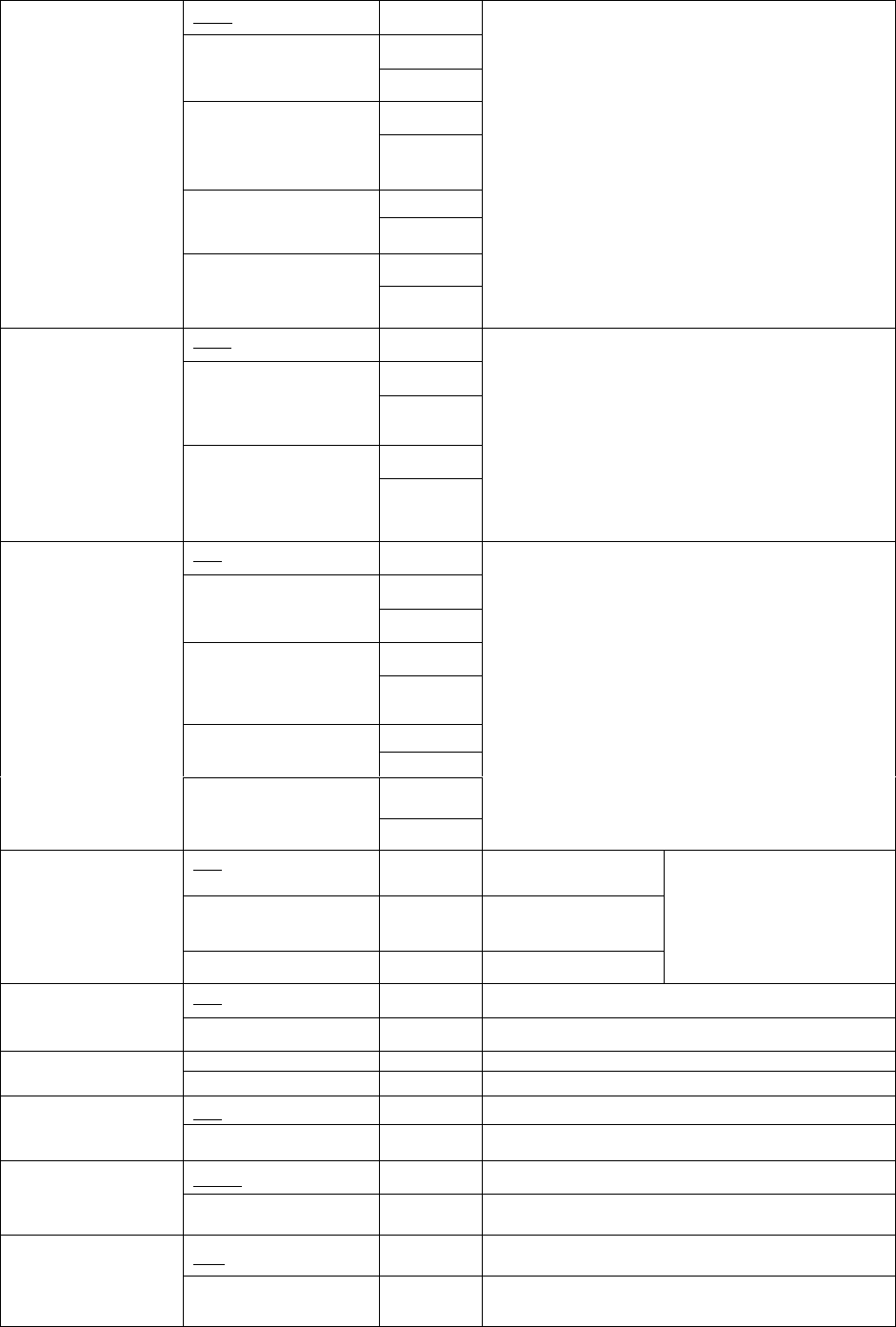
Function
Name
Settings (Defaults are underlined)
Display Remarks
CH 1 Channel
Select 1CH ~ 99CH 1CH CH 99 “RX FREQUENCY” setting follows this setting.
Blank ------------
100.00000 100.000MHz or more
Under 550MHz (2.5KHz steps)
549.99750
100.00000
RX
FREQUENCY
100.000MHz or more
Under 550.000.MHz
(6.25KHz steps) 549.99375
frequency change→Channel Selector knob
Toggle between 6.25/2.5KHz steps→ [●] key
(Dot means 6.25KHz)
Toggle between blank/frequency→[□] key
Change to 1MHz steps→[LAMP] + Channel
Selector knob
The initial value when changing from blank to
frequency display is the initial value of the
destination.
Enter “RX Signaling” setting after each frequency is
set.(If blank is set, setting returns to the option of “
Channel Select”)
16
OFF OFF
QT 67.0 CTCSS (standard)
67.0Hz ~ 250.3Hz QT 250.3
QT 67.0* CTCSS (not standard)
(0.1Hz step)
67.0Hz ~ 250.3 Hz
QT 250.3*
DQT023N
CDCSS (standard)
DQT754I
DQT000N*
RX CTCSS
SIGNALING
CDCSS (not standard)
(step:1) 000.~777.
(octonary) DQT777I*
Code selection → Channel Selector knob
CTCSS changes in 0.1 Hz step increment → [●] key
CDCSS changes in 1 step increment,→ [●] key
Toggle signaling between CDCSS and –CDCSS→[○].
Toggle among blank, CTCSS frequency and
CDCSS→[□] key
“TX FREQUENCY” follows this setting.
Blank -------------
100.00000 100.000MHz or more
Under 550MHz (2.5KHz
steps) 549.99750
100.00000
TX
FREQUENCY
100.000MHz or more
Under 550.000MHz
(6.25KHz steps) 549.99375
frequency change → Channel Selector knob
Toggle between 6.25/2.5KHz step increment → [●] key
Toggle between Blank/ CTCSS display→[□] key
Change to 1MHz step increment → [LAMP]+Channel
Selector knob
The initial value from blank to frequency display is the
value set in RX FREQUENCY
If blank is set, menu enters to the option of “DTMF
SIGNALING”.
OFF OFF
QT 67.0 CTCSS (standard)
67.0 HZ ~ 250.3Hz QT 250.3
QT 67.0* CTCSS (not standard)
(0.1Hz step mode) 67.0Hz
~ 250.3Hz QT 250.3*
DQT023N CDCSS (standard)
DQT754I
DQT000N*
TX CTCSS
SIGNALING
CDCSS (not standard)
(step:1)
000.~777. (octonary) DQT777I*
select codes → Channel Selector knob
CTCSS changes in 0.1Hz step increment →[●] key.
CDCSS changes in 1 step increment→[●] key.
Toggle signaling between CDCSS and –CDCSS→[○]
key.
Toggle among blank, CTCSS frequency and
CDCSS→[□] key.
“DTMF SIGNALING/2-Tone” settings follow this setting
OFF SIG OFF No DTMF Signaling/2
Tones
DTMF SIG DTMF Use DTMF Signaling
DTMF/2-TONE
SIGNALING
2 Tones SIG TTS Use 2 Tones
[ANI] function setting follows
this setting.
OFF ANI OFF Disable ANI ANI
ON ANI ON Enable ANI
ADD SCAN ADD Set in scan lis
t
SCAN DELETE/ADD
DELETE SCAN DEL Delete from scan list
OFF B.C.L.O Busy Channel lock out is disabled
BUSY CHANNEL
LOCK OUT ON B.C.L.O ON Busy Channel lock out is enabled
Disable SHFT OFF Do not shift clock frequency
CLOCK SHIFT
Enable SHFT ON Shift clock frequency
High TXPWR H Permit switching between High/Low Power
TX POWER
Low TXPWR L Permit only Low Power
17
Note:
1. If DTMF or DTMF/2-Tone is disabled, “ID code” function option is automatically skipped.
2. DTMF and 2-Tone cannot be enabled simultaneously.
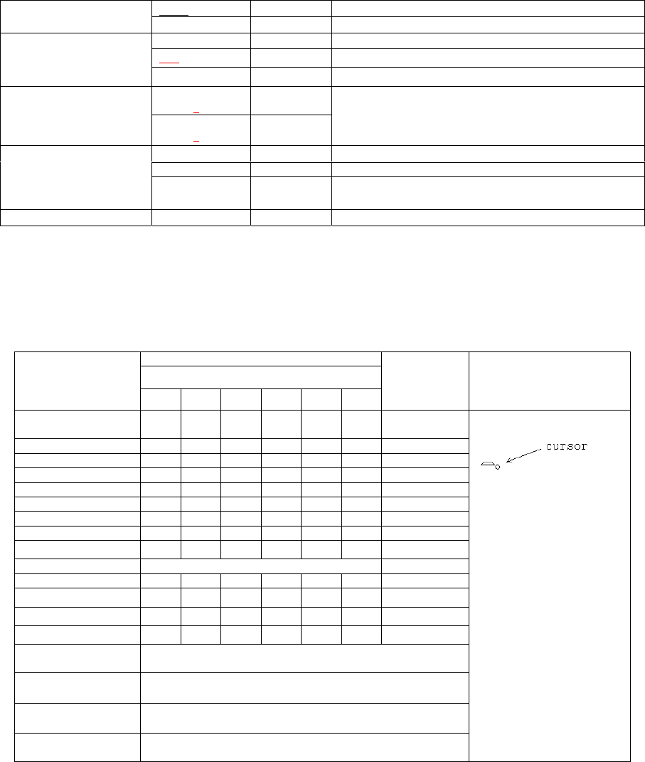
Appendix 1: Channel Label Programming
CHARACTER INPUT
Number of times key is pressed
KEY
1 2 3 4 5 6
NUMBER
INPUT
REMARKS
1 Spac
e
1
2 A B C 2
3 D E F 3
4 G H I 4
5 J K L 5
6 M N O 6
7 P Q R S 7
8 T U V 8
9 W X Y Z 9
0 A ~ Z 0
A @ # $ % ^ * A
B , . ‘ “ ? : B
C + - \ / = _ C
D < > ( ) [ ] D
* /T9 Press to toggle between Character and Number. “V” on
LCD indicates number input.
# → (Next alphanumeric)
PTT Enter (Complete programming and store channel label)
Channel selector
knob
←, → (Move cursor backward/forward)
Cursor: current input
position will toggle between
char/num and cursor
display.
Each key can generate
numeric and character
information.
Pressing a key will cause
the first character of the
key’s character cycle to
appear on the LCD;
Subsequent pressing of the
same key will cause
subsequent characters in
the cycle to appear. For
example, to enter the
character “S”, press the “7”
key four (4) times.
Wide WIDE Wide mode
Wideband/Narrowband Narrow NARROW Narrow mode
ID
Display about one seconds when entering this setting.
000 -------0 ID is input, enter number→[10 digit keys(0-9)]
ID CODE
(DTMF)
9999999999 9999999999 If more than 8, scroll it
RX 2-TONE
1-16 1
TTS_R 1
2-Tone signaling TX 2-TONE
1-16 1
TTS_T 1
Code selection→Channel selector knob
Return to “Channel Select” function when 99 channels are
not all set.
When 99 channels are all set, END is displayed.
CH LABEL Display about one seconds when entering this setting.
-------- ------- No channel label is input
Channel Label
POLICE 1 POLICE 1 Maximum 16 characters (0-9,A-Z, symbols)
(Refer to appendix 1: channel label programming)
END END Only appears in 99th channel
18
Appendix 2: CTCSS Frequency
Appendix 3: 2-Tone frequency (Default)
No. Tone A
Freq [Hz] Tone B
Freq [Hz] Tone A
Dur. (s) Tone B
Dur. (s) Gap Time (s)
1 400 1141 0.5 0.5 0.5
2 456 1301 0.5 0.5 0.5
3 520 1483 0.5 0.5 0.5
4 593 1690 0.5 0.5 0.5
5 675 1927 0.5 0.5 0.5
6 770 2197 0.5 0.5 0.5
7 878 2504 0.5 0.5 0.5
8 1001 2855 0.5 0.5 0.5
9 1141 400 0.5 0.5 0.5
10 1301 456 0.5 0.5 0.5
11 1483 520 0.5 0.5 0.5
12 1690 593 0.5 0.5 0.5
13 1927 675 0.5 0.5 0.5
14 2197 770 0.5 0.5 0.5
15 2504 878 0.5 0.5 0.5
16 2855 1001 0.5 0.5 0.5
Wired Clone Mode
Connect the source radio and the target radio with an interface cable.
Source radio
Operation
1. Turn POWER ON while holding down [LAMP] and [○] key, in about 2 seconds the radio enters the Dealer Mode.
Then press [LAMP] to enter Clone Mode.
No. Frequency [Hz] No. Frequency [Hz] No. Frequency [Hz] No. Frequency [Hz]
1 67.0 11 94.8 21 131.8 31 186.2
2 69.3 12 97.4 22 136.5 32 192.8
3 71.9 13 100.0 23 141.3 33 203.5
4 74.4 14 103.5 24 146.2 34 210.7
5 77.0 15 107.2 25 151.4 35 218.1
6 79.7 16 110.9 26 156.7 36 225.7
7 82.5 17 114.8 27 162.2 37 233.6
8 85.4 18 118.8 28 167.9 38 241.8
9 88.5 19 123.0 29 173.8 39 250.3
10 91.5 20 127.3 30 179.9
[LAMP]
19
2. Transmit the clone data by pressing [MONI], red LED glows during data transfer. When data transfer is completed,
“END” is displayed on LCD, and the red LED turns off.
3. When “End” is displayed, press [MONI] button to continue to clone another radio or press [LAMP] to return to Dealer
Mode.
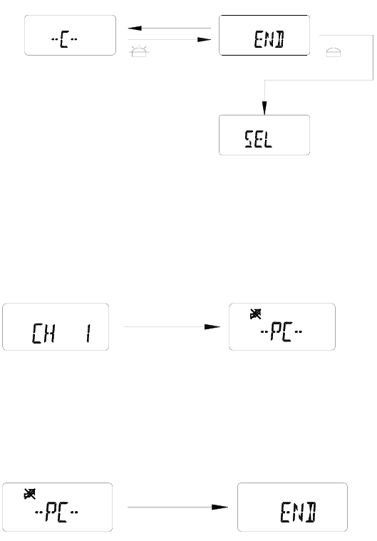
Target radio
Operation
1. Turn On the power. When data is being sent from the master, busy mark and "-PC-" appears on LCD.
2. When all data is received, “END” displays on LCD.
After the “END” appears, operation is same as the source radio operation 3.
Note:
During cloning, do not execute any action that might interrupt the cloning such as shutting off power.
Wireless Clone Mode
Setup the source side and target side.
Source Side
Operation
1. Turn POWER ON while holding down [LAMP] and [○] key, in about 2 seconds radio enters the Dealer Mode. Then
press [MONI], radio enters Wireless Clone Mode, now the frequency displayed on LCD is the initial frequency
matching the destination.
Clone ModeDealer Mode
[LAMP]
Sending clone data Red LED on clone data transfer end Red LED off
Dealer Mode
[MONI]
20
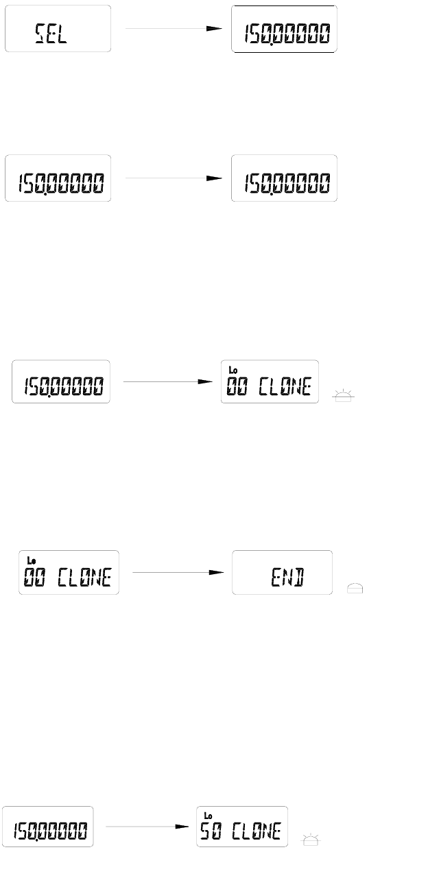
2. Turn Channel Selector knob to select the frequency used for the wireless clone.
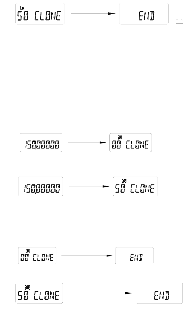
3. Start the first half (00-50%) data transmission by pressing [PTT]. “00 CLONE” is displayed on LCD and red LED
glows. The leftmost digits (00) on LCD show data transfer rate, and as data transmission proceeds, the digits count
upwards in increments of 1. Transmit power is set as LOW POWER.
4. When the first half data transfer is completed, the LED turns off and “END” is displayed. Press [MONI], radio
returns to Clone Mode and you can clone another half by pressing [LAMP] or return to Dealer Mode by pressing
[MONI] key.
5. You can continue to clone another half (50-100%) data mainly about channel label after one minute to
avoid long time transmission.
6. Start another half (50-100%) data transmission by pressing [LAMP]. “50 CLONE” is displayed on LCD and
red LED glows. The leftmost digits (50) on LCD show data transfer rate, and as data transmission
proceeds, the digits count upwards in increments of 1. Transmit power is set as LOW POWER.
Clone ModeDealer Mode
[ MONI ]
Clone ModeDealer Mode
[Channel Selector]
Red LED lights up
Clone Mode Clone Mode
[PTT]
Clone ModeClone Mode
Red LED lights up
Clone Mode
Clone Mode
[LAMP]
21
7. When the second half data transfer is completed, the LED turns off and “END” is displayed. Press [MONI],
radio returns to Clone Mode and you can clone another radio or press [MONI] to return to Dealer Mode.
Target Side
Operation
1. Turn POWER ON while pressing [LAMP] and [○] key, in about 2 seconds radio enters the Dealer Mode. Then press
[MONI] to enter Wireless Clone Mode. The frequency displayed on LCD is the initial frequency matching the
destination.
2. The display changes to “00 CLONE” or “50 CLONE” correspondingly when the radio receives data from the master
and the BUSY mark appears. The leftmost digits (00) or (50) on the LCD show the data transfer rate and as data
reception proceeds, the digits count upwards in increments of 1.
3. When all data is received, “END” displays. The display of first half and second half transfer is shown as following
respectively.
4. When “END” displays, the next operation is same as the source side operation 4.
Please confirm the following operations:
Clone Mode
[Receive DTMF Data]
Clone Mode
[Data receive complete]
Clone ModeClone Mode
Clone ModeClone Mode
Clone Mode
[Receive DTMF Data]
Clone Mode
[Data receive complete]
Clone Mode Clone Mode

22
(1) Attach the antenna to the source radio.
(2) Remove the antenna from the target radio.
(3) Keep radios as close as possible.
Note:
During cloning do not execute any action that might interrupt the cloning such as shutting off power.
TEST MODE
Menu Mode
1. Turn the power ON while pressing [LAMP] and [■] key, in about 2 seconds the radio enters Test Mode and LCD
displays “TEST”. After two seconds, the first setting option “ADJUST” is displayed on LCD. Turn Channel Selector
knob to select from the following menu:
ADJUST
FREQ TST
TUNE CLN
FULL LCD
DEST SET
2. Press [□] key to enter Adjustment Mode, Frequency Test Mode, Adjustment Data Clone Mode, LCD Full Screen
Mode or Destination Set Mode.
3. Press [■] key to return to the Menu Mode.
LCD Full Screen Mode
1. Turn the power ON while pressing [LAMP] and [■] key simultaneously, in about 2 seconds the radio enters the menu of
Test Mode.
2.
Turn Channel Selector knob to select the setting option: “FULL LCD”.
3. Now press [□] key to enter LCD Full Screen Mode.
4. Press [■] key to exit from LCD Full Screen Mode. LCD displays “FULL LCD”.
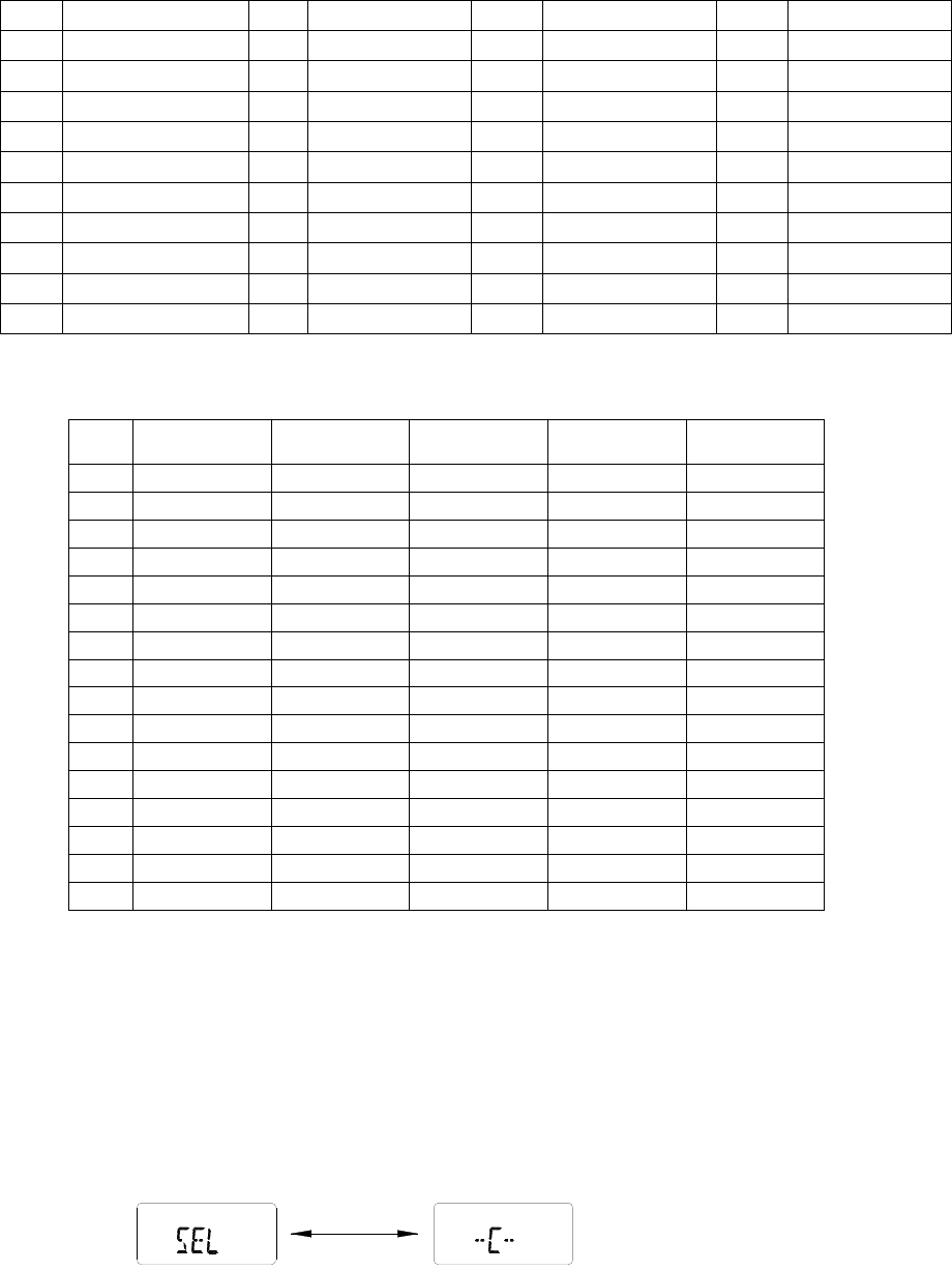
Adjustment Data Clone Mode
1. Turn the power ON while pressing [LAMP] and [■] key, in about 2 seconds the radio enters the menu of Test
Mode.
2. Turn Channel Selector knob to select the setting option “TUNE CLN”.
LCD Full Screen ModeTest Mode
[ ¡ ö ]
[ ¡ õ ]
23
3. Connect the source radio and the target radio with an interface cable.
4. Turn the target radio on.
5. Now press [□] key to enter Adjustment Data Clone Mode. LCD displays “–C–“.
6. Press [MONI] key to transmit the adjustment data.
7. Red LED glows during data transfer. When data transfer is completed, “END” is displayed on LCD and red LED
turns off.
8. When “End” is displayed, press [MONI] to continue to clone another radio.
9. Press [■] key to exit from Adjustment Data Clone Mode. LCD displays “TUNE CLN”.
Destination Set Mode
Operation
1. Turn the power ON while pressing [LAMP] and [■] key, in about 2 seconds the radio enters the menu of Test Mode.
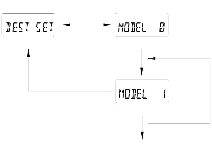
2. Turn Channel Selector knob to select the setting option “DEST SET”.
3. Now press [□] key to enter Destination Set Mode, LCD displays “ MODEL X“. (X=0~15)
4. Turn Channel Selector knob to change the destination number. (Display numbers change from 0 to 15).
5. Hold down [MONI] key and then press [□] key to select the display number that you need as the destination.
6. Press [LAMP] key to reverse CDCSS decoder and LCD displays “V”. (For factory setting only).
7. Press [■] key to exit from Destination Set Mode. LCD displays “DEST SET”.
Note:
[ ¡ ö ]
Test Mode
Destination on dispiay is stored in the memory
[Channel Selector]
Destination Set Mode
Destination Set Mode
[PTT]
[ ¡ õ ]
[
MONI
]
+
[
□
]

24
1. Once the destination is set, previous channel settings (frequencies, CTCSS and channel functions) will be deleted and
some functions are also changed. Therefore, do not make destination set except when EEPROM is replaced or other
unavoidable conditions happened.
2. Destination of RPV599APlus is set as 8, frequency is 148~174MHz. And destination of RPU499APlus is 11,
frequency 450-470MHz.
Frequency Test Mode (for frequencies checking and radios repairing)
Operation
1. Turn POWER ON while pressing [LAMP] and [■] key, in about 2 seconds the radio enters the menu of Test Mode.
2. Turn Channel Selector knob to select the setting option “FREQ TST”.
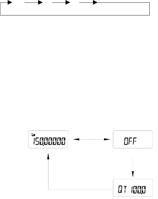
3. Press [□] key to enter Frequency Display Mode. LCD displays frequency.
4. Turn Channel Selector knob to increase/decrease the frequency.
5. Press [○] key to switch the step increments.
6. Press [□] key to toggle between High and Low Power.
7. Press [●] key, the radio enters scan mode.
8. Press [PTT] to transmit and [MONI] to monitor.
9. Hold down [LAMP] and then press [○] key, the radio enters CTCSS set mode.
10. Press [■] key to exit from Frequency Display Mode, LCD displays “FREQ TST”.
Notes:
1. The reset (initial) frequency varies according to the destination.
2. Set initial transmit power to LO POWER.
Changing the Frequency
Operation
1. In Frequency Test Mode, turn Channel Selector knob clockwise, the frequency increases in step increments. Turn the
knob counterclockwise, the frequency decreases in step increments.
2. Hold down the [LAMP] key, and then turn the Channel Selector knob to change the frequency in 1MHz step
increments.
3. Press [○] key, the step increment is switched in the following order.
Frequency Display Mode
[ ¡ ö ]
[ ¡ õ ]
Test Mode
25
2.5KHz 6.25KHz 5KHz 12.5KHz
Notes:
1. The frequency display range is between 100MHz and 550MHz. When PLL is unlocked, “beeps” sound. The frequency
should not be out of corresponding frequency spectrum.
2. Step increment is not displayed on LCD.
CTCSS
Operation
1. In Frequency Test Mode, hold down [LAMP] and then press [○] key, the radio enters CTCSS set mode. Turn Channel
Selector knob to change the CTCSS frequency.
2. Press any key to select the CTCSS you need and the radio returns to frequency display mode.
Notes:
1. The selected CTCSS is set for both transmit and receive.
2. The selected CTCSS frequency cannot be changed in 0.1Hz step increments.
3. During test scan, even if [○] key and [LAMP] are simultaneously held down, the radio will not enter
CTCSS set mode.
Adjustment Mode (Adjustment procedure used during radio repairing)
Menu Mode
1. Turn POWER ON while pressing [LAMP] and [■] key, in about 2 seconds, the radio enters the menu of Test Mode.
LCD displays “TEST” for 2 seconds and then begins to display “ADJUST”.
2. Turn Channel Selector knob to select the setting option “ADJUST”.
3. Now press [□] key to enter Adjustment Mode, the first option “HI POWER” is displayed on LCD.
4. Turn Channel Selector knob to select a setting option from the following menu:
HI POWER
LO POWER
BATT REF
CTCSS W
CDCSS W
[Channel Selector]
[KEY]
[LAMP]+[DIAL]
[
LAMP
]
+
[
○
26
CTCSS N
CDCSS N
SQL CEN
SQL LOW
SQL HIGH
5. Press [□] key to adjust the Transmit High Power, Transmit Low Power, Battery Reference Value, CTCSS Deviation
(Wideband), CDCSS Deviation (Wideband), CTCSS Deviation (Narrowband), CDCSS Deviation (Narrowband),
BUSY Reference Value (Center Frequency), BUSY Reference Value (Low Frequency) and BUSY Reference Value
(High Frequency) individually.
6. Press [■] key to exit from the Adjustment Mode and return to the menu of Test Mode. LCD displays “ADJUST”.
Adjusting Transmit High Power
Use this procedure to adjust the transmit High Power level.
1. Connect the power meter to the radio.
2. Turn Channel Selector knob to select the setting option “HI POWER”.
3. Transmission is performed automatically at High Power when the [□] key is pressed. After the frequency is displayed
for one second, the display “HPWR XXX” now appears. (XXX=0 to 255)
4. Turn the channel selector knob while observing the power meter to obtain the transmit power needed. Turn the
channel selector knob clockwise for an increase in power, and counterclockwise for a decrease in power.
5. Press [□] key to store the alignment value into the memory and return to the “LO POWER” display. Press [■] key to
cancel the alignment value and return to the “HI POWER” display.
Adjusting Transmit Low Power
Use this procedure to adjust the transmit Low Power level.
1. Connect the power meter to the radio.
2. Turn Channel Selector knob to select the setting option “LO POWER”.
3. Transmission is performed automatically at Low Power when the [□] key is pressed. After the frequency is displayed
for one second, the display “LPWR XXX” now appears. (XXX=0 to 255)
4. Turn the channel selector knob while observing the power meter to obtain the transmit power needed. Turn the
channel selector knob clockwise for an increase in power, and counterclockwise for a decrease in power.
5. Press [□] key to store the alignment value into the memory and return to the “BATT REF” display. Press [■] key to
cancel the alignment value and return to the “LO POWER” display.
Adjusting the Battery Reference Value
Use this procedure to adjust the reference value for issuing battery low voltage alarms.
1. Using an external power supply feed in the reference value at which you wish to trigger the alarm.
2. Turn Channel Selector knob to select the setting option “BATT REF”.
3. Transmission is performed automatically at High Power when the [□] key is pressed. After the frequency is displayed
for one second, the display “BATT XXX” now appears. (XXX=1 to 255).
4. Adjust by turning the Channel Selector knob counterclockwise so that the red LED lights up and turning clockwise so
27
that the red LED flashes. The point where the red LED is flashing indicates detection of the low voltage.
5. Press [□] key to store the alignment value into the memory and return to the “CTCSS W” display. Press [■] key to
cancel the alignment value and return to the “BATT REF” display.
Adjusting CTCSS Deviation (Wideband)
Use this procedure to adjust the transmit CTCSS deviation (Wideband).
1. Connect the modulation analyzer to the radio.
2. Turn Channel Selector knob to select the setting option “CTCSS W”.
3. Transmission is performed automatically at Low Power and the preset CTCSS is sent when the [□] key is pressed.
After the frequency is displayed for one second, the display “CTCW XXX” now appears (XXX=1 to 255). If the
CTCSS is set OFF, then 67.0Hz is sent.
4. Hold down [LAMP] button to observe CTCSS and adjust CTCSS by turning Channel Selector knob.
5. While observing the modulation analyzer, adjust the deviation with the Channel Selector knob.
6. Press [□] key to store the alignment value into the memory and return to the “CDCSS W” display. Press [MONI] to
cancel the alignment value and return to the “CTCSS W” display.
Adjusting CDCSS Deviation (Wideband)
Use this procedure to adjust the transmit CDCSS deviation (Wideband).
1. Connect the modulation analyzer to the radio.
2. Turn Channel Selector knob to select the setting option “CDCSS W”.
3. Transmission is performed automatically at Low Power and the preset CDCSS is sent when the [□] key is pressed.
After the frequency is displayed for one second, the display “CDCW XXX” now appears (XXX=1 to 255). If the
CDCSS is set OFF, then 023 is sent.
4. While observing the modulation analyzer, adjust the deviation with the [CHANNEL SELECTOR].
5. Press [□] key to store the alignment value into the memory and return to the “CTCSS N” display. Press [■] key to
cancel the alignment value and return to the “CDCSS W” display.
Adjusting CTCSS Deviation (Narrowband)
Use this procedure to adjust the transmit CTCSS deviation (Narrowband).
1. Connect the modulation analyzer to the radio.
2. Turn Channel Selector knob to select the setting option “CTCSS N”.
3. Transmission is performed automatically at Low Power and the preset CTCSS is sent when the [□] key is pressed.
After the frequency is displayed for one second, the display “CTCN XXX” now appears (XXX=1 to 255). If the
CTCSS is set OFF, then 67.0Hz is sent.
4. Hold down [LAMP] button to observe CTCSS and adjust CTCSS by turning Channel Selector knob.
5. While observing the modulation analyzer, adjust the deviation with the Channel Selector knob.
6. Press [□] key to store the alignment value into the memory and return to the “CDCSS N” display. Press [■] key to
cancel the alignment value and return to the “CTCSS N” display.
28
Adjusting CDCSS Deviation (Narrowband)
Use this procedure to adjust the transmit CDCSS deviation (Narrowband).
1. Connect the modulation analyzer to the radio.
2. Turn Channel Selector knob to select the setting option “CDCSS N”.
3. Transmission is performed automatically at Low Power and the preset CDCSS is sent when the [PTT] key is pressed.
After the frequency display for one second, the display “CDCN XXX” now appears (XXX=1 to 255). If the CDCSS is
set OFF, then 023 is sent.
4. While observing the modulation analyzer, adjust the deviation with the Channel Selector knob.
5. Press [□] key to store the alignment value into the memory and return to the “SQL CEN” display. Press [■] key to
cancel the alignment value and return to the “CDCSS N” display.
Adjusting the BUSY Reference Value (Center Frequency)
Use this procedure to align squelch level 3 and 9 at center frequency.
1. Connect the signal generator to the radio.
2. Turn Channel Selector knob to select the setting option “SQL CEN”.
3. Input a signal at the level at which you want squelch 9 to open.
4. Press [□] key to receive this signal. After the center frequency is displayed for one second, the display “SQL9 XXX”
now appears. (XXX =1 to 255)
5. Turn Channel Selector knob to the position where you want the squelch to open. Rotate Channel Selector knob
clockwise, the squelch is tightened.
6. Press and hold [LAMP] button to observe the center frequency and adjust the frequency by Channel Selector knob.
7. Press [■] key to cancel the setting and return to the “SQL CEN” display. Press [□] key to save the alignment value
into the memory and continue to the alignment of squelch 3, and now “SQL3 XXX” displays. (XXX=1 to 255)
8. Then output a signal from the signal generator at which you want squelch 3 to open. Adjust by using the Channel
Selector knob just same as with squelch 9.
9. Press [□] key to store the alignment value into the memory and return to the “SQL LOW” display. Press [■] key to
cancel the alignment value and return to the “SQL CEN” display.
Adjusting the BUSY Reference Value (Low Frequency)
Use this procedure to align squelch level 3 and 9 at low frequency.
1. Connect the signal generator to the radio.
2. Turn Channel Selector knob to select the setting option “SQL LOW”.
3. Input a signal at the level at which you want squelch 9 to open.
4. Press [□] key to receive this signal. After the low frequency is displayed for one second, the display “SQL9 XXX”
now appears. (XXX =1 to 255)
5. Turn Channel Selector knob to the position where you want the squelch to open. Rotate Channel Selector knob
clockwise, the squelch is tightened.
6. Press and hold [LAMP] button to observe the low frequency and adjust the frequency by Channel Selector knob.
7. Press [■] key to cancel the setting and return to the “SQL LOW” display. Press [□] key to save the alignment value

29
into the memory and continue to the alignment of squelch 3, and now “SQL3 XXX” displays. (XXX=1 to 255)
8. Then output a signal from the signal generator at which you want squelch 3 to open. Adjust by using the Channel
Selector knob just same as with squelch 9.
9. Press [□] key to store the alignment value into the memory and return to the “SQL HIGH” display. Press [■] key to
cancel the alignment value and return to the “SQL LOW” display.
Adjusting the BUSY Reference Value (High Frequency)
Use this procedure to align squelch level 3 and 9 at high frequency.
1. Connect the signal generator to the radio.
2. Turn Channel Selector knob to select the setting option “SQL HIGH”.
3. Input a signal at the level at which you want squelch 9 to open.
4. Press [□] key to receive this signal. After the high frequency is displayed for one second, the display “SQL9 XXX”
now appears. (XXX =1 to 255)
5. Turn Channel Selector knob to the position where you want the squelch to open. Rotate Channel Selector knob
clockwise, the squelch is tightened.
6. Press and hold [LAMP] button to observe the high frequency and adjust the frequency by Channel Selector knob.
7. Press [■] key to cancel the setting and return to the “SQL HIGH” display. Press [□] key to save the alignment value
into the memory and continue to the alignment of squelch 3, and now “SQL3 XXX” displays. (XXX=1 to 255)
8. Then output a signal from the signal generator at which you want squelch 3 to open. Adjust by using the Channel
Selector knob just same as with squelch 9.
9. Press [□] key to store the alignment value into the memory and return to the “HI POWER” display. Press [■] key to
cancel the alignment value and return to the “SQL HIGH” display.
Destination Set
Busy Channel
Lockout
Model Default
Frequency
(MHz)
DTMF CDCSS CDCSS
TX/RX
with
Same
Phase
2-Tone
CTCSS/
CDCSS
DTMF/
2-Tone
First
IF
(MHz)
Busy
Channel
Lockout
Center
(MHz)
Low
(MHz)
High
(MHz)
Remarks
0 143 √ √ √ 45.05
*1*2143 136 150
1 160 √ √ √ 45.05 12 160 148 174
2 410 √ √ √ 46.35 12 410 400 420
3 455 √ √ √ 45.05 12 455 440 470
4 460 √ √ √ 45.05 12 460 450 470
5 480 √ √ √ 45.05 12 480 470 490
6 490 √ √ √ 46.35 12 490 480 500
7 140 √ √ √ √ 45.05 1 140 136 150
8 160 √ √ √ √ 45.05 1 160 148 174
9 410 √ √ √ √ √ 46.35 1 410 400 420
10 455 √ √ √ √ 45.05 1 455 440 470
11 460 √ √ √ √ 45.05 1 460 450 470
30
12 480 √ √ √ √ 45.05 1 480 470 490
13 490 √ √ √ √ √ 46.35 1 490 480 500
14 360 √ √ 46.35 1 360 350 370
15 380 √ √ 45.05 1 380 370 390
Note: About busy channel lockout
*1: Transmission is prohibited if a signal appears with incompatible CTCSS/CDCSS;
*2: Transmission is prohibited if a signal appears with incompatible CTCSS/CDCSS or DTMF/2-Tone.
ALL RESET MODE
Operation
1. Turn POWER ON while pressing [LAMP] and [○] key, in about 2 seconds, the radio enters the Dealer Mode.
2. In dealer mode, press [PTT] and [□] key simultaneously to enter All Reset Mode. The EEPROM data is reset. No
change displays on LCD, and red LED glows.
3. The LED turns off when All Reset is completed.
PC MODE
Connection procedures
1. Connect the radio of RPV599APlus/RPU499APlus to the personal computer with an interface cable.
2. Run the program on the computer and Turn ON the power of the radio.
3. You can read, programme or adjust the radio via RPV599APlus/RPU499APlus programming software.
Please refer to “RPV599APlus/RPU499APlus Editing Software User Manual” for details.
Red LED onRed LED off
All Reset Complete
All Reset
Dealer Mode
[PTT]+[LO]
[
PTT
]
+
[
□