RELM Communications SRU50ABC Repeater User Manual manual
RELM Communications Inc Repeater manual
Contents
- 1. manual
- 2. manual pt2
manual
1/98
RELM Communications, Inc
SR35/50 RF Transceiver/Repeater
USER MANUAL
RELM Communications, Inc
7505 Technology Drive
W. Melbourne, Florida 32904
Voice: 407- 984-1414
Fax: 407-984-0434
S Series Repeater USER MANUAL
©RELM Communications Inc. Revision 1.0
2
Manual Revision 1.0 January 1998
Applicable reference:
Micro Controller Board Rev C
In order to continually improve our products, RELM Communications, Inc reserves the right to alter, without notice
and at any time, the equipment and specifications described in this document.
All performance figures quoted are typical and are subject to normal manufacturing and service tolerances.
The purchaser is warned that statements made in this document may be inaccurate due to typographical or other
errors or subsequent modifications of the product. While every care has been taken in the creation of this document,
no warranty of accuracy or reliability is given in any advice or information contained in this document. The
responsibility for any loss or damage whatsoever arising in any way or any representation, act or omission whether
express or implied (including responsibility to any person by reason of negligence) is not accepted by RELM
Communications, Inc or any officer, agent or employee of RELM Communications Inc.
Copyright © RELM Communications, Inc.

S Series Repeater USER MANUAL
©RELM Communications Inc. Revision 1.0 3
Record Of Changes
Any changes to this manual are recorded on this list.
Date Manual Version Chapter Changes Pages Changed
Jan 1998 1.0 All - Initial Release All

S Series Repeater USER MANUAL
©RELM Communications Inc. Revision 1.0
4
SAFETY SUMMARY
Although there are no dangerous mains voltages present within the
equipment, the following general safety precautions as would normally
apply, should be observed during all phases of operation, service and
repair of this equipment.
AROUND THE EQUIPMENT.
To minimize any possible shock hazard from an external power supply or lightning strike,
the chassis or equipment cabinet must be connected to an electrical ground. Provide
adequate ventilation around the rear of the equipment.
DO NOT OPERATE IN AN EXPLOSIVE ATMOSPHERE.
Do not operate the equipment in the presence of flammable gases or fumes. Operation
of any electrical equipment in such an environment constitutes a definite safety hazard.
DO NOT ATTEMPT INTERNAL SERVICE WHILE TRANSMITTING.
Thermal or RF burns may result from touching certain components within the power
amplifier module while transmitting or operating the transmitter.
DO NOT SUBSTITUTE PARTS OR MODIFY THE EQUIPMENT.
Because of the danger of introducing additional hazards, do not install substitute or lower
voltage parts to the equipment. Return to your authorized distributor.
EXERCISE CAUTION AND CORRECT DISPOSAL OF RF POWER DEVICES.
Most RF power transistors and some RF power hybrids contain Beryllium Oxide.
Although they are normally safe, if physically damaged toxic dust may be released.
Consult your local authority for correct disposal thereof.
S Series Repeater USER MANUAL
©RELM Communications Inc. Revision 1.0 5
Contents
CONTENTS...........................................................................................................................................................5
INTRODUCTION.................................................................................................................................................7
GENERAL DESCRIPTION ...........................................................................................................................................7
Exciter Module Description ..............................................................................................................................7
Receiver Module Description............................................................................................................................8
Power Amplifier Module Description................................................................................................................8
KEY FEATURES AND ADVANTAGES..........................................................................................................................8
INDICATORS AND CONNECTORS...............................................................................................................................9
Standard Version front panel ............................................................................................................................9
OEM Version front panel ..................................................................................................................................9
Rear Panel Connectors ...................................................................................................................................11
REAR VIEW SR35/50..............................................................................................................................................11
SIDE VIEW SR35/50 ...............................................................................................................................................12
INSTALLATION................................................................................................................................................12
TECHNICAL DESCRIPTION..........................................................................................................................13
INTERNAL CONNECTIONS.......................................................................................................................................13
EXCITER MODULE TECHNICAL DESCRIPTION.........................................................................................................14
RECEIVER MODULE TECHNICAL DESCRIPTION ......................................................................................................14
PA MODULE TECHNICAL DESCRIPTION .................................................................................................................14
MICRO CONTROLLER CONFIGURATION ..................................................................................................................15
Description of Micro Controller Jumper functions.........................................................................................16
TESTING.............................................................................................................................................................17
CONNECTING A COMPUTER TO THE SR35/50 RADIO...............................................................................................17
TEST SETUP ...........................................................................................................................................................17
TEST PROCEDURE..................................................................................................................................................18
SR35/50 BASE STATION UTILITY ................................................................................................................18
INITIAL SETUP AND DESCRIPTION..........................................................................................................................18
Main Display Tool Bar Description................................................................................................................18
Initial Settings .................................................................................................................................................18
Initial Static Settings .......................................................................................................................................18
Channel Programming and Description .........................................................................................................18
QUICK FREQUENCY PROGRAMMING..........................................................................................................19
FULL CALIBRATION.........................................................................................................................................19
DESCRIPTION OF PROGRAM FUNCTIONS.................................................................................................................20
Synthesizer Control .........................................................................................................................................20
Modulation Control.........................................................................................................................................21
Transmit RF Power Output .............................................................................................................................21
CTCSS Control................................................................................................................................................21
Channel selection ............................................................................................................................................21
TROUBLESHOOTING .....................................................................................................................................22
GLOSSARY.........................................................................................................................................................22
S Series Repeater USER MANUAL
©RELM Communications Inc. Revision 1.0
6
APPENDIX A SPECIFICATIONS ...................................................................................................................24
MINIMUM PERFORMANCE SPECIFICATION..............................................................................................................24
GENERAL SPECIFICATIONS.....................................................................................................................................24
TRANSMITTER MODULE SPECIFICATIONS...............................................................................................................25
RECEIVER MODULE SPECIFICATIONS .....................................................................................................................26
ANCILLARIES .........................................................................................................................................................26
APPENDIX B INTERFACE CONNECTIONS................................................................................................27
SR35/50 REAR CHASSIS CONNECTOR DESCRIPTION..............................................................................................27
Universal DB15 Analog I/O............................................................................................................................27
DB25 Digital I/O Connector ...........................................................................................................................29
PC SERIAL PORT TO RADIO CABLE ........................................................................................................................29
APPENDIX C DIP SWITCH SETTINGS ........................................................................................................30
DIP SWITCH 1 CHANNEL SELECTION.....................................................................................................................30
DIP SWITCH 2 USER FUNCTION SELECT................................................................................................................36
APPENDIX D MODEL # CONFIGURATION GUIDE..................................................................................37
S Series Repeater USER MANUAL
©RELM Communications Inc. Revision 1.0 7
Introduction
The SR35/50 series of radio systems employ state of the art design and construction methods to deliver a range of
high performance, ultra reliable radio devices. They are ideally suited for use in VHF or UHF two way voice radio
systems, however the SR35/50 can perform any number of applications where the added advantage of linear
frequency and phase response from DC to 5KHz can be utilized. The SR35/50, unlike conventional PLL radio
systems, uses a two point modulation method synthesizer for extended low end VF transmit frequency response.
The flexibility of the SR35/50 series allows them to be configured for a wide range of applications, including;
• Standard or wideband voice, full duplex radio.
• Cellular or Trunking systems.
• POCSAG paging transmitter.
• Direct FSK modulation.
• 2 or 4 level FSK transmissions.
• Other paging formats.
• Cross band link or repeater.
General Description
The SR35/50 series features a high degree of RFI and EMI screening throughout their design and construction. The
receiver and exciter (low power transmitter) modules are contained in a solid machined aluminum enclosure, and for
additional screening each interface pin is individually filtered. The PA module is contained in a special compact
extrusion for minimum harmonic radiation. In addition to this the RF modules and the micro controller are also
contained in the main screened 2RU case for low conducted and radiated emissions and minimal susceptibility to
RFI and EMI.
The SR35/50 series consists of four main sub assemblies as outlined below: an Exciter Module, a Receiver Module,
a Power Amplifier Module and a Micro Controller board. For further information on these sub assemblies, refer to
the Technical Description section later in this manual.
Exciter Module Description
The Exciter module features a modulation bandwidth to DC with an ultra wide RF bandwidth 20MHz to 1000MHz
at an output power of 300mW. To change from one band to another, all that is required is to change the plug in VCO
board, no other manual adjustment or change is required. Should a high stability reference be required, the RF
modules can be fitted with connectors for an external reference oscillator input. On board memory stores calibration,
personality information and program data. Alternatively, the exciter module can be set up as a conventional PLL
should simplicity and minimum cost be required. The fractional N synthesizer provides ultra low spurious while still
maintaining fast lock times even at 6.25KHz step size or less. An optional built turn around mixer (TRM) provides
advanced diagnostics such as receiver sensitivity tests.
S Series Repeater USER MANUAL
©RELM Communications Inc. Revision 1.0
8
Receiver Module Description
The Receiver module features the same advanced synthesizer and wide bandwidth as the exciter. Only the front end
bandpass filter and VCO need to be changed in order to support different frequency bands, resulting in significant
flexibility and end-user cost savings. The custom built front end bandpass filter has a wide no-adjust bandwidth
equal to the band allocation. The receiver has extremely high sensitivity while maintaining excellent intermodulation
immunity and adjacent channel rejection. A double first IF provides excellent rejection to common known spurious
responses. High blocking of over 120dB typical ensures that strong interfering signals do not desensitize the receiver
when receiving weak signals.
Power Amplifier Module Description
The PA is very compact and efficient for high reliability and low cost. The heatsink has minimal temperature rise
even under continuous operation, this also ensures the best MTBF obtainable for a practical design. A low loss 13
element elliptical low pass filter ensures that any harmonics remain below -100dBc.
Key Features and Advantages
• Exceptional system performance.
• Modular internal construction.
• Software or hardware configurable.
• 50 Watt continuous transmitter (30 Watt above 800 MHz).
• Programming via RS232.
• 256 channel capacity.
• Optional CTCSS.
• Paging capability.
• VF filters and processing can be bypassed.
• Fast mute.
• 20mS Rx and Tx. 4mS selectable.
• Front panel display.
• Digital squelch compatible.
• Wide band Rx and Tx.
• Isolated PTT input.
• Digitally controlled and corrected Tx deviation.
• Programmable Tx power.
• Direct FSK or paging compatible.
• VSWR and Temp protection.
• Compact 2RU case.
• 13.8 Volt operation.
• Available in continuous coverage from 66-88MHz, 135-520MHz and 805-960MHz.
• Surface mount technology used throughout.
S Series Repeater USER MANUAL
©RELM Communications Inc. Revision 1.0 9
• Rear analog and digital interfaces.
Other options and variations available, please consult RELM Communications, Inc. for further details.
Indicators and Connectors
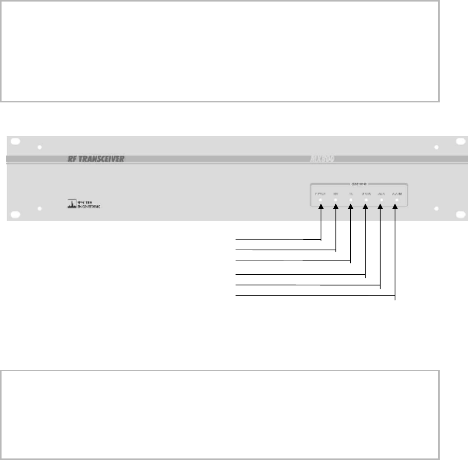
The SR35/50 series can be supplied with custom front panels. The standard and OEM versions are shown below.
The following tables explain the functions of the front panel LEDs. Each LED indicates the status of the SR35/50
base station in real time.
Standard Version front panel
LED FUNCTION
POWER Indicates the power supply voltage is within software selectable limits.
RX A signal is being received by the receiver or the receivers squelch is open.
TX The transmitter is transmitting RF power.
CTCSS A valid Continuous Tone Coded Squelch Signal has been detected.
AUX Aux function is selected or the PLL is unlocked.
ALARM A general alarm condition exists such as under / over voltage or over temperature.
LEDS: POWER
RX
TX
CTCSS
AUX
ALARM
Front panel
LED FUNCTION
POWER Indicates the power supply voltage is within software selectable limits.
RX A signal is being received by the receiver or the receivers squelch is open.
TX The transmitter is transmitting RF power.
LOW V Indicates the power supply voltage is below the software selectable limit.
LOCK The RX PLL is locked correctly or the TX is keyed and the PLL is in lock.

S Series Repeater USER MANUAL
©RELM Communications Inc. Revision 1.0
10
HI TEMP Indicates the power amplifier's temperature has exceeded the software selectable
limit.
S Series Repeater USER MANUAL
©RELM Communications Inc. Revision 1.0 11
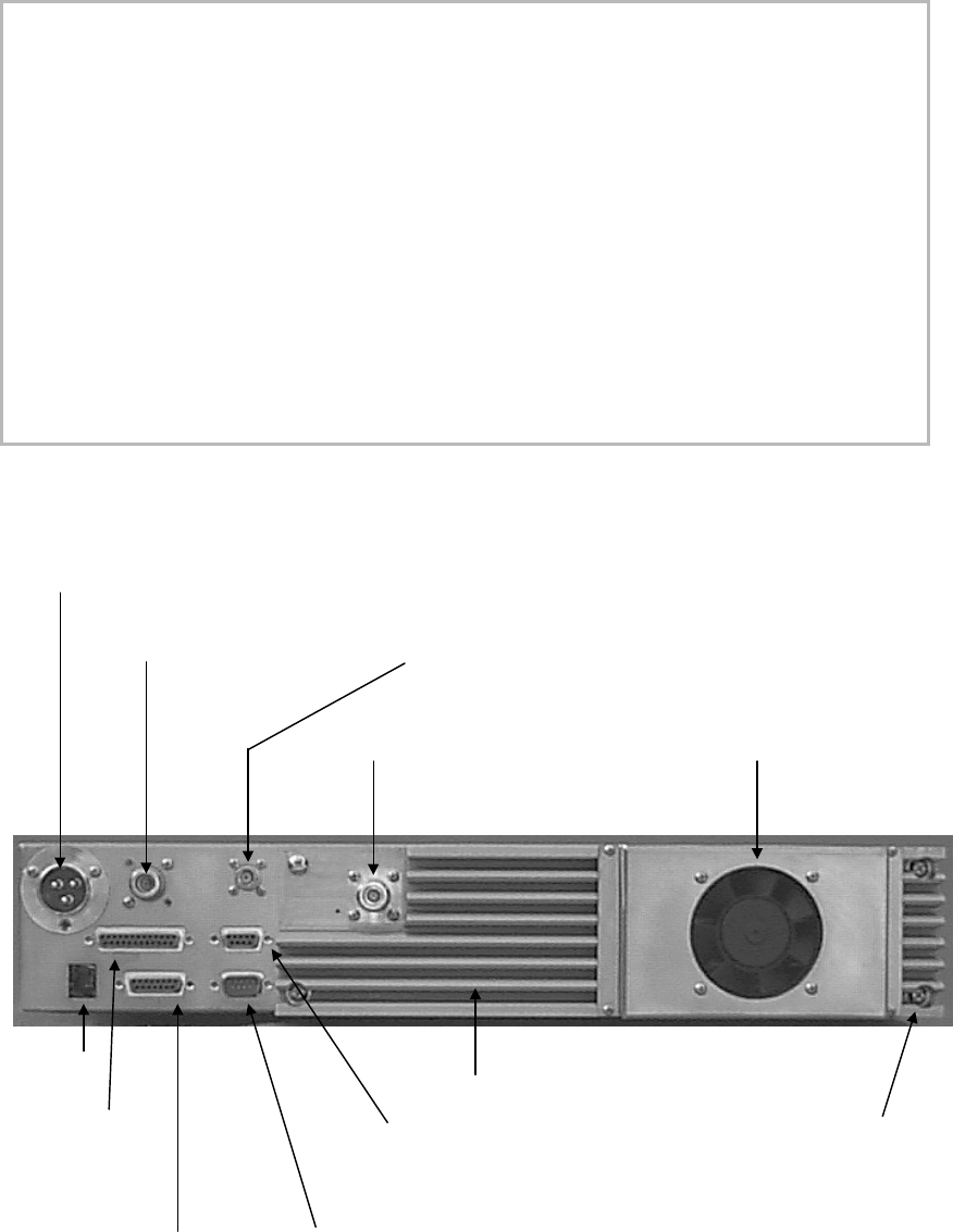
Rear Panel Connectors
CONNECTOR DESCRIPTION
DC POWER INPUT 13.8 Volt DC power input. Also +28 Volt input on spare pin.
SIMPLEX RELAY OUT OR
N TYPE RX INPUT Location for internal simplex relay. The antenna for RX / TX
connects to this point. Else a N-Type connector can be used for the
input to the receiver for full duplex operation.
BNC RX INPUT Standard BNC connector for the input to the receiver for full
duplex operation.
N TYPE TX OUTPUT The RF power output from the transmitter for full duplex operation.
SPARE RJ11 Provision for internal expansion.
DB25-F PARALLEL I/O Provides two 8 bit input ports, where one is used as the parallel
BCD channel select. Also one spare 8 bit input port.
DB15 UNIVERSAL
ANALOG I/O Provides the necessary analog receiver and transmitter interface for
system expansion.
RS-232 SERIAL PORT 9600 Baud serial port for frequency programming, channel
selection and alarm and status monitoring.
SPARE DB15 Provision for internal expansion.
Rear view SR35/50
DC POWER INPUT
SIMPLEX RELAY OUT
OR N TYPE RX INPUT OR BNC RXINPUT
N TYPE TX OUTPUT THERMALLY CONTROLLED FAN
SPARE
RJ11 TRANSMITTER HEATSINK
HOLE SPARE 4 OFF SCREWS FOR
DB25-F DB15 EASY PA MODULE
PARALLEL I/O HOLE REMOVAL
DB15 UNIVERSAL RS-232
ANALOG I/O SERIAL PORT
S Series Repeater USER MANUAL
©RELM Communications Inc. Revision 1.0
12
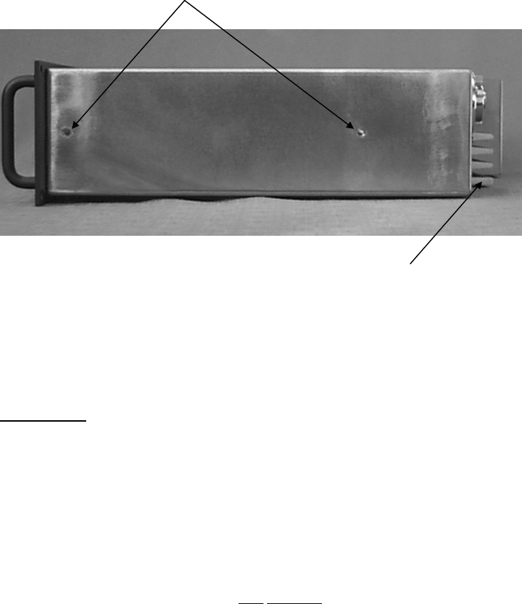
Side view SR35/50
MOUNTING HOLES FOR SLIDE-OUT RAILS
THE HEATSINK AIRFLOW EXITS SIDEWAYS SO ANY NUMBER OF SR35/50
CAN BE STACKED IN A RACK ONE ABOVE THE OTHER
Installation
WARNING: Ensure that all safety precautions are observed when working with electrical
and electronic equipment. Please contact RELM Communications if you
are in any doubt about the suitability of your test environment.
SR35/50 series radio systems are securely packed for transport in polystyrene foam peanuts, within a pasteboard
container. Before unpacking the SR35/50 radio, please inspect the packaging for signs of damage and report any
damage to your SR35/50 distributor.
Upon unpacking of the SR35/50 radio, please ensure that all items shipped were received, report any missing items
to your SR35/50 distributor. All ports on the rear of the radio should be carefully examined to ensure that packaging
has not become wedged inside them. It is very important to examine the fan as operation of the radio will be effected
if any packaging causes the fan to stop working.
If you intend to install the radio in an equipment rack, consult the installation manual for your system. RELM
Communications recommends that the radio is secured into the rack system using four screws through the mounting
holes in the front panel, near the handles.
If the radio is to be used in a stand alone configuration, ensure that it is in a secure,
dry location with sufficient air space around it to allow for adequate ventilation.
S Series Repeater USER MANUAL
©RELM Communications Inc. Revision 1.0 13
Technical Description
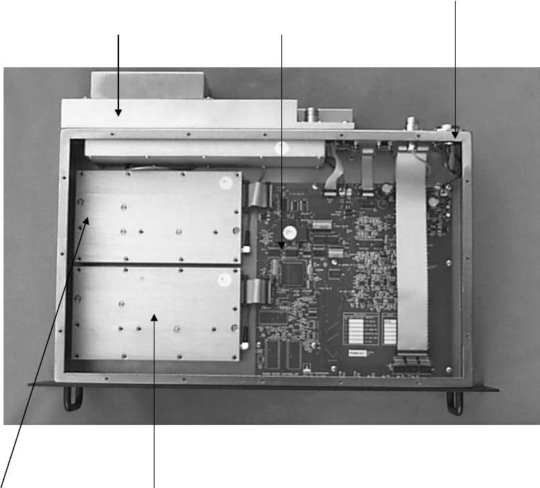
Internal Connections
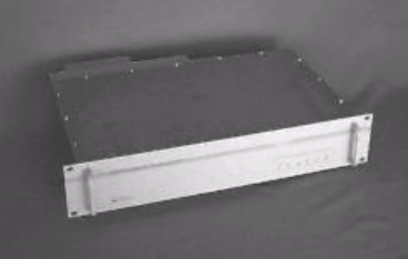
The internal design of the SR35/50 is of a modular nature, allowing for simple configuration and maintenance while
ensuring minimal downtime. For reference purposes, an image of a typical SR35/50 system is shown below.
WELDED SEALED CHASSIS CONSTRUCTION
PA MODULE MICRO CONTROLLER
EXCITER MODULE RECEIVER MODULE
S Series Repeater USER MANUAL
©RELM Communications Inc. Revision 1.0
14
Exciter Module Technical Description
RF from the VCO, at a nominal level of +3dBm, is applied to the fractional-N synthesizer IC main divider input, a
second, separate RF output of the same level from the VCO is used as the main transmit RF amplifier signal source.
The main signal is first buffered by a very high isolation circuit consisting of a 10dB pad and a MMIC amplifier. The
signal is further amplified by a variable gain wide band amplifier with 40dB control range and power output of
300mW. The drive power of this stage, is used to set the output power of the main power amplifier. The synthesizer's
charge pump output is filtered then amplified by the non inverting low noise op amp. The op amp uses a 25 volt
power supply so as to provide a wide tuning range voltage to the frequency control varicaps located on the VCO
board.
The VCO boards and synthesizer circuits are the same for the exciter and receiver modules. The VCO consists of a
10mm ceramic coaxial resonator with common base oscillator for low phase noise for bands 805-960 MHz.
Frequencies below 520 MHz use an LC tank circuit. The power supply to the VCO consists of a its own 8 volt
regulator and active filter for maximum noise rejection. For standard modulation, transmit audio is fed to the
conventional point of the VCO varactor. For 2 point modulation, audio is also fed to the voltage control pin of the
VC-TXCO, this in effect cancels out the PLL error that would otherwise have occurred for low audio frequencies,
hence resulting in a flat VF response.
Receiver Module Technical Description
The receive signal from the antenna enters a 3 section Bandpass filter which provides the initial filtering for the front
end amplifier. The front end amplifier is a broad band high performance MMIC with a gain of 20dB, NF of 4dB and
3rd OIP of +36dB. This is then followed by the second 3 section BPF, then a high level double balanced mixer. RF
from the VCO is buffered and amplified to +17dBm and injected in the high level mixer which down converts the
signal to the IF frequency of 90 MHz. The IF signal of 90 MHz from the mixer is terminated by a bi-directional
constant impedance diplexer network and is then amplified by a bipolar amplifier with a gain of 15dB and 3rd OIP
of +35dB. This provides a high degree of intermodulation rejection for the receiver. This stage is followed by a 4
pole 90 MHz crystal filter with its associated matching networks. The signal is further amplified and filtered by a
transistor and its associated 2 pole crystal filter before being fed into the main IF demodulator chip with a second IF
frequency of 455 KHz. The resulting audio is passed out to the micro controller board.
PA Module Technical Description
RF from the exciter is first attenuated by a 50 ohm pad which is used to provide a good 50 ohm source impedance
for the high power hybrid amplifier. The RF is amplified to between 5 and 13 watts at its 50 ohm output. The signal
from the hybrid is then matched by a broad band network to drive the low input impedance associated with the final
transmit power amplifier transistor. The transistors low collector impedance is then also matched back to 50 ohms
with a broad band matching network. Several trimmer capacitors enable adjustment of the power amplifier over a
wide bandwidth so as to maintain good conversion efficiency.
The dual directional coupler consists of coupled microstrip transmission lines fabricated on the PCB artwork. The
sampled RF energy is rectified to provide a proportional DC voltage output. Prior to transmission a low loss 13
element elliptical low pass filter, filters out the unwanted harmonics to less than -100dBc.
S Series Repeater USER MANUAL
©RELM Communications Inc. Revision 1.0 15
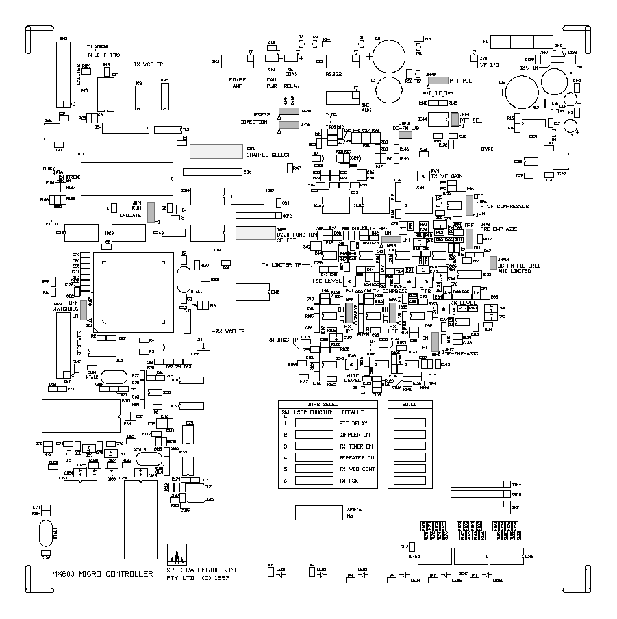
Micro Controller Configuration
The view below is an image of the micro controller layout and the position of the jumpers and DIP switches
(highlighted) which are used for setting the general configuration of the audio filters, PTT functions and other
various facilities.
NOTE: Not all components shown are fitted.

S Series Repeater USER MANUAL
©RELM Communications Inc. Revision 1.0
16
Description of Micro Controller Jumper functions
JMP # FUNCTION / DESCRIPTION
JMP 1 Selects either default RUN or EMULATE mode for the micro processor.
JMP 2 Enables the WATCHDOG auto reset function in the micro processor.
JMP 3 Enables or disables the PRE-EMPHASIS for the Tx audio.
JMP 4 Enables or disables the COMPRESSOR for the Tx audio.
JMP 5 Enables or disables the HIGH PASS FILTER for the Rx audio.
JMP 6 Enables or disables the LOW PASS FILTER for the Rx audio.
JMP 7 Enables or disables the DE-EMPHASIS processing for the Rx audio.
JMP 8 Selects a common earth or floating PTT input. Also see Appendix B.
JMP 9 Selects the PTT mode. Also see Appendix B.
JMP 10 Controls the direction of the RS-232 Tx and Rx data. Also see the next section and Appendix B.
JMP 11 Controls the direction of the RS-232 Tx and Rx data. Also see the next section and Appendix B.
JMP 12 Enables a direct connection to the Tx modulation. Not normally used. Also see Appendix B.
JMP 13 Enables or disables the HIGH PASS FILTER for the Tx audio.
JMP 14 Enables a direct connection to the Tx modulation via the limiter and post LPF.
Also see Appendix B.

S Series Repeater USER MANUAL
©RELM Communications Inc. Revision 1.0 17
Testing
The following equipment is required to test SR35/50 series radios:
• A Radio communications test set with 600 Ω interfaces.
• A digital multimeter.
• An oscilloscope.
• 13.8V Power Supply.
• A PC compatible personal computer with at least 8Mb of RAM, a serial port and the "SR35/50 Base Station
Utility" software installed.
• A suitable cable to connect the serial port of the PC to the SR35/50 radio’s RS-232 port. The details of this cable
can be found in Appendix B.
• A suitable power lead as supplied with the radio is being tested.
• Suitable low loss RF cables and connectors.
WARNING: Attempting to operate the transmitter without an appropriate load
connected to the RF output may cause physical damage to the unit and void
the warranty. Please contact RELM Communications if you are in any
doubt about the suitability of your test environment.
Connecting a computer to the SR35/50 radio.
The standard cable used to connect the computer to the SR35/50 is a serial "Lap-Link" type cable. This usually
consists of a lead with a DB9 and DB25 female connector at each end. The Rx and Tx data signals are cross
connected in "Lap-Link" type cables. There are two jumper links on the Micro Controller circuit board inside the
SR35/50 designated JMP10 and JMP11, their default position is pin 2&3 or "SWAP". This indicates that a lead
which swaps Rx and Tx data is in use.
Other special serial leads can also be used. In order to allow for more combinations you can set JMP10 and JMP11
to position 1&2 or "NORM" which has the effect of swapping over pins 2 and 3 on the DB9 rear connector.
Test Setup
All connections are made at the rear of the SR35/50.
Connect the Transmitter RF output located on the heatsink module to the dummy load / Tx test input of the Radio
Communications Test Set using a short length of low loss RG 213 or equivalent coaxial cable.
Connect the Receiver RF input to the Signal Generator output of Radio Communications Test Set using moderate to
low loss coaxial cable.
Connect all VF interfaces' and control lines to the appropriate points.
Connect the SR35/50 Radio to a suitable 13.8 Volt DC power supply while observing the correct polarity.
S Series Repeater USER MANUAL
©RELM Communications Inc. Revision 1.0
18
Test Procedure
Refer to Calibration Procedure.
SR35/50 Base Station Utility
Initial Setup And Description
Main Display Tool Bar Description
The "Channel Info" button is used to view and setup the frequency information in the SR35/50.
The "Analyze" button reads the internal status of the SR35/50 and displays as such.
The "Update" button is only used when SETUP - DYNAMIC is selected. Pressing "Update" sends the dynamic
settings to the SR35/50 for quick initial testing. The values are not saved in the SR35/50. It is also used to setup the
default values as used in the channel programming.
The other buttons duplicate "Save", "Open File", "Send Data to Radio" and "Load Data from Radio" as seen on the
Channel Info screen respectively.
Initial Settings
In order to read or send data to the SR35/50 a file must first be created or opened.
Initial Static Settings
Go to SETUP STATIC and set the appropriate values and conditions for the SR35/50. Press "SEND" to send and
store the values inside the SR35/50. Note that reference, IF frequencies and injection are not stored in the SR35/50,
so this must reflect the actual physical conditions of the SR35/50. The standard reference oscillator is 14.4MHz. The
Standard IF is 90MHz, with high side injection Bands A to I and low side J to X. The PLL correction factor value is
usually around 120. The fan on temperature is normally set to 40C with the over temperature cutout at 70C.
Channel Programming and Description
S Series Repeater USER MANUAL
©RELM Communications Inc. Revision 1.0 19
In the Channel Info screen click on the channel you wish to setup. You can view all of the settings and calibration
data, however you will need to enter the password by clicking the "Advanced" button to proceed. This level of
protection is provided to advise that changes may allow the transmitter to potentially cause interference to vital radio
communications services. See also the QUICK FREQUENCY PROGRAMMING and FULL CALIBRATION
sections.
QUICK FREQUENCY PROGRAMMING
( If a calibrate has already been performed)
In the channel information screen, click the channel number you wish to change or create. Enter into the
"Advanced" mode with the correct password. Enter the frequencies' of the channel. Inject an audio signal with
sufficient level (~0dBm) to ensure compressor operation and check the deviation is 3KHz for 25KHz channel
spacing or 1.5KHz for 12.5KHz spacing. Adjust the VCO deviation for the correct level. Most of the other settings
will not change. If in doubt see the FULL CALIBRATION section.
FULL CALIBRATION
(TX MODULATION) Suggested Method
Recommended Full Calibration Procedure with DC-FM installed. The alignment may be carried out in the SETUP
DYNAMIC for a quicker result. Calibration is performed on the center RF frequency.
1. Set the Reference Level to 0 and the Reference Bias to 127.
2. On the SR35/50 Micro controller Board set Pre-emphasis, Tx HPF and the Tx VF Compressor to OFF. Turn the
Tx Compress Level RV2 fully clockwise to maximum. This will allow the hard limiter to operate.
3. Inject a 1KHz audio signal into the Tx VF input at a level of +10dBm. Check with an oscilloscope that the audio
signal is clipped at the Tx Limiter Test Point.
4. Set the VCO Level to achieve 4.8KHz deviation (clipped waveform) in the case of 25KHz channel spacing and
2.3KHz deviation in the case of 12.5KHz channel spacing. If CTCSS is used then subtract further the nominal
CTCSS system deviation level.
5. Reduce the level from the audio oscillator to obtain a sinewave modulation, now vary the modulation frequency
around 50 to 500Hz and adjust the Bin Accel Factor for an approximately flat response.
Caution: Do not enter too low a value or the lock time and stability will be affected.
Return the audio level to +10dBm.
6. Set the modulation frequency to about 300Hz. Observe the demodulated clipped sinewave with drooping positive
and negative deviation peaks. Now increase the "Ref Level" and the degree of drooping will reduce. Adjust so that
flat top is observed on the demodulation waveform. Check that if you vary the modulation frequency across a range
of 50Hz to 1KHz the frequency response is flat. The peak deviation should still be the same as in step 4, if not repeat
steps 4 and 6.
S Series Repeater USER MANUAL
©RELM Communications Inc. Revision 1.0
20
Note: The modulation flatness will rise around 2KHz if the SR35/50 is fitted with Butterworth or Chebychev type
filters for the main limiter post LPF as used in the EIA-603 Build. It is due to the filters group delay distortion. For
a flatter response ensure the standard Bessel filter is fitted.
7. Set the transmitter carrier center frequency by adjusting the "Ref Bias" Level if necessary. Check again step 6 as
there is some interaction from the reference oscillator due to non-linearity. Repeat as necessary.
8. Save as defaults.
9. Return the jumpers as previous in step 2. Adjust the Tx Compress Level RV2 for the standard system deviation
level. Usually 3KHz for 25KHz channel spacing and 1.5KHz for 12.5KHz spacing.
10. Set the VF level to the standard input level (-10dBm) and adjust the compress Tx VF Gain to just compress.
11. Go to the Channel Info screen and click on the channel number to be allocated to the calibration results. Click
on Get Defaults, then OK.
12. Go to the next channel and load defaults. Key in the appropriate RF frequencies and set the VCO Level for the
same deviation as in step 9. Repeat this step for all the channels required. Note that a small error will result in the
calibration of the "Ref Level" as in step 6 if the next channel frequency varies greatly from the original cal
frequency. Recalibrate the "Ref Level" if necessary.
Caution: Due the high degree of adjustment available in the SR35/50, check the PLL stability by
monitoring the PLL tune voltage with a CRO at the onset of PTT for minimal ringing.
Description of Program Functions
Synthesizer Control
The SR35/50 Base Station has the facility for precise software control of the PLL characteristics. This provides user
with additional flexibility and capability for specialized or precise setting. The following program functions allow for
control of the fractional-N synthesizer and are described as such:
PLL Correction Factor: Controls the relative amount of charge current into the PLL charge - pump circuit. The
value for the PLL Correction Factor is loaded into the receiver and exciter synthesizer during normal operation. It is
primarily used to control the dynamic PLL settling characteristics. A value of 0 will provide a minimum current and
hence a slow and under damped loop response. A value of 255 will provide the maximum current and hence a fast
and overdamped loop response.
Bin Accel Main: Same as PLL Correction Factor except that the value for the Bin Accel Main is only loaded into
the exciter synthesizer during the transmitter modulation period. It is primarily used to control the static PLL
characteristics. This will allow adjustment for a maximally flat modulation response near the cutoff frequency of the
PLL. A value of 0 will provide a minimum current and hence an under damped response. A value of 255 will
provide the maximum current and hence an overdamped response.
Modulo: A modulo value of 8, sets the synthesizer comparison frequency to 8 times that of the Channel Spacing
(synthesizer step size). A value of 5 is 5 times respectively.
S Series Repeater USER MANUAL
©RELM Communications Inc. Revision 1.0 21
Channel Spacing: May also be referred to as the synthesizer step. As a rule the oscillator frequency must be
integer divisible by the modulo value and then the step size. The step size is usually set to half that of the channel
spacing.
Accel Proportion: Controls the degree of speedup at the onset of PTT.
Accel Integral: Controls the multiplication factor of the Accel Proportion.
For further information and reading, you may refer to the Philips Semiconductor Data Book for the SA7025DK chip.
Modulation Control
DC-FM uses two point modulation and its parameters can be set by the following:
VCO Deviation: The digital pot value sets the modulation level fed to the VCO's modulation input. A value of 0
sets the minimum deviation level. A value of 255 sets the maximum deviation level.
Reference Bias: The digital pot value sets the center carrier frequency of the transmitter frequency. A value of 0
sets the highest carrier frequency. A value of 255 sets the lowest carrier frequency. A value around 128 is normally
used. If the value is to high or too low this may result in unsymmetrical modulation distortion due to the limited
range of the master reference oscillator.
Reference Level: The digital pot value sets the modulation level fed to the master reference oscillator. A value of 0
sets the minimum deviation level. A value of 255 sets the maximum deviation level. It primarily is used to set the
modulation balance at low frequencies.
Transmit RF Power Output
Transmit Power: The digital pot value sets the RF drive level to the power amplifier. A value of 0 sets the
transmitter power to minimum. A value of 255 sets the transmitter power to maximum.
CTCSS Control
Tx Subtone: Enters directly the frequency of the transmitter's modulation encoder.
Rx Subtone: Enters directly the frequency for the receiver's decoder to operate.
Tx Subtone Level: This value controls the level of the transmitter's modulation encoder. Steps are 0.85dB.
Channel selection
Three methods are available for channel selection.
S Series Repeater USER MANUAL
©RELM Communications Inc. Revision 1.0
22
Software Channel Select via Utility Program: First ensure that channel 0 is selected on the DIP switch DIP1 located
on the Micro Controller Board (all 8 switches in the off position). Enter the channel number in the Software Select
Channel window on the Channel Info screen and press Select.
Software Channel Select via Serial Command: First ensure that channel 0 is selected on the DIP switch DIP1
located on the Micro Controller Board (all 8 switches in the off position). Send the string "chansXXX" where XXX
= a 3 digit number for the channel number. eg To select channel 5 send the string "chans005". Baud rate is 9600
BPS.
Hardware Channel Select: Select the fixed channel for the SR35/50 by using the DIP switch DIP1 located on the
Micro Controller Board. Channel 1 to 255 is available in binary selection. Switch position 1 is channel 1, position 2
is channel 2, position 3 is channel 4, position 4 is channel 8, position 5 is channel 16, position 6 is channel 32,
position 7 is channel 64, position 8 is channel 128. For further details of all possible channels see APPENDIX C.
Troubleshooting
The most common causes of problems are listed below.
Incorrect parameters set in SR35/50 Utility Program such as
1. Wrong Reference frequency oscillator value.
2. PLL correction factor or Bin Accel value too low.
3. Accel values extreme.
4. Channel spacing value not correct.
5. Frequency value is not a multiple of the channel spacing / step size.
Other problems may include Jumpers or DIP switches in wrong positions
Glossary
3RD OIP Third Order Intercept Point
4LFSK 4 Level Frequency Shift Keying
APCO-25 Associated Public-Safety Communications Officers, Inc. Project 25
AUX Auxiliary
BPF Band Pass Filter
BW Bandwidth
CMOS Complementary Metal Oxide Silicon
CRO Cathode Ray Oscilloscope
CTCSS Continuous Tone Coded Squelch System
DC Direct Current
DIP Dual Inline Package
DDS Direct Digital Synthesis
DSP Digital Signal Processor
EMI Electro Magnetic Interference
FSK Frequency Shift Keying
HPF High Pass Filter
IC Integrated Circuit
IF Intermediate Frequency
I/O Input / Output
S Series Repeater USER MANUAL
©RELM Communications Inc. Revision 1.0 23
JMP Jumper
LC tank circuit Resonant circuit consisting of an Inductor and Capacitor network
LED Light Emitting Diode
LPF Low Pass Filter
MMIC Microwave Monolithic Intergrated Circuit
Mobitex Radio messaging system
MTBF Mean Time Between Failure
NF Noise Figure
PA Power Amplifier
Pad Circuit board land
PCB Printed Circuit Board
PLL Phase Locked Loop
PPM (ppm) Parts Per Million
PTT Push To Talk
POCSAG Post Office Code Standardization Advisory Group
RAM Random Access Memory
RF Radio Frequency
RSSI Received Signal Strength Indicator
RU Rack Unit
Rx Receiver
Simplex Single operation of either Transmitter or Receiver
S/N Signal to Noise Ratio
Squelch Muted audio signal
SW Switch
TEMP Temperature
TRM Turn Around Mixer
Tx Transmitter
UHF Ultra High Frequency
VCO Voltage Controlled Oscillator
VC-TXCO Voltage Controlled Temperature Compensated Crystal Oscillator
VF Voice Frequency
VHF Very High Frequency
VSWR Voltage Standing Wave Ratio
S Series Repeater USER MANUAL
©RELM Communications Inc. Revision 1.0
24
Appendix A Specifications
Minimum Performance Specification
Minimum performance to exceed the following for 66MHz to 960MHz*:
ETS 300 086 Jan 1991
FCC Part 90
TIA/EIA-603
BAPT 225 ZV 1/2098 (German Softkeying)
CEPT T/R 24-01 E Sept 1988
EC Marking, EC EMC Directive 89/336/EEC
ETS 300 113
MIL-STD-810E
RFS32
TIA/EIA-603
General Specifications
SR35/50 Rack Size: 2RU Case, 330mm deep inc fan.
SR35/50 Overall Physical Size 89mm high, 360mm deep, 483mm wide
Supply Voltage: 13.8V +/- 20%.
Power Consumption: <600 mA receive, typical 440 mA.
<11A for 50W Tx RF.
Operating Temperature: -10 to +60 C. -30 to +60 C option.
Individual Module Dimensions: Rx & Tx W=100, L=180, H = 30mm.
PA W=78, L=300, H = 60mm.
Standard LED indicators: Power, Rx, Tx, CTCSS, Aux, Alarm.
Frequency Range: Coverage 66-960 MHz.
Synthesis Method: Non mixing PLL
Fractional N synthesizer.
Modulation: Direct FM, +/- 5 KHz
+/-2.5 KHz narrow band.
Channel Spacing: 30 KHz, 25 KHz or 12.5 KHz.
Synthesizer Step Size: 30, 25, 12.5, 7.5 or 6.25KHz.
Channels: 256 Software or switch selectable
1-99 BCD parallel selection.
S Series Repeater USER MANUAL
©RELM Communications Inc. Revision 1.0 25
Frequency Range: Coverage 66-960 MHz.
Other frequencies or band allocations available.
Contact RELM Communications for details.
Band A 66-80 MHz.
Band B 74-88 MHz.
Band C 135-160 MHz.
Band D 155-180 MHz.
Band E 175-200 MHz.
Band F 195-225 MHz.
Band G 220-250 MHz.
Band H 245-275 MHz.
Band I 270-300 MHz.
Band J 295-325 MHz.
Band K 320-350 MHz.
Band L 345-375 MHz.
Band M 370-400 MHz.
Band N 395-430 MHz.
Band O 425-460 MHz.
Band P 455-490 MHz.
Band Q 485-520 MHz.
Band R 805-825 MHz.
Band S 824-849 MHz.
Band T 850-870 MHz.
Band U 872-905 MHz.
Band V 890-915 MHz.
Band W 917-950 MHz.
Band X 925-960 MHz.
Transmitter Module Specifications
RF Power Output: 5W to 50W (66-520 MHz).
5W to 35W, 50W optional for
13.8V/28V rail(800-960 MHz).
100W on special request.
Frequency Stability: 2.5PPM, 1.5PPM or 1.0PPM.
Audio Response: Flat within +/- 0.5dB across BW.
Bessel LPF for data or Chebychev LPF
Audio Bandwidth: DC(J-X Band) to 3400Hz base band
(-0.5dB) 300Hz to 3000Hz for EIA-603
300Hz to 3400Hz nominal.
Modulation Distortion: Less than 2% C-weighted.
S/N Ratio: Better than 50dB, wide band.
Better than 44dB, narrow Band.
Spurious: Better than -90dBc.
RF Switching Bandwidth: Same as band allocation.
RF Switching Bandwidth PA: 10MHz nominal, full band useable.
Duty Cycle: 100% for 50W RF output with
S Series Repeater USER MANUAL
©RELM Communications Inc. Revision 1.0
26
Thermal controlled fan.
RF Rise Time: 4mS with continuous VCO selected
(Controlled RF envelope).
Receiver Module Specifications
Sensitivity: Better than -117dBm for 12dB ( 25 KHz spacing ), C-
weighted, De-emphasis. Typical -120dBm
Selectivity 66-520MHz (Option): More than 80 dB for 25 KHz adj channel, more than 70 dB for
12.5 KHz adj channel, for switching BW 10MHz minimum.
Selectivity 66-520MHz: More than 75 dB for 25 KHz adj channel, more than 65 dB for
12.5 KHz adj channel, for switching BW same as band
allocation.
Selectivity 805-960MHz: More than 70 dB for 25 KHz adj channel more than 65 dB for
12.5 KHz adj channel for switching BW same as band
allocation.
Spurious Resp: Better than 90dB.
Intermodulation: Better than 80dB.
Blocking: Better than 100dB at +/- 1MHz point.
Distortion: Less than 2%.
S/N Ratio: Better than 50dB C-weighted, wide band. Better than 44dB C-
weighted, narrow band .
RF Switching Bandwidth: 10MHz minimum or equal to band allocation.
Receiver Front End BW: Equal to band allocation, no retuning.
Audio Bandwidth: DC to 3400Hz (-0.5dB)
Squelch Opening Time: 20mS.
Squelch Closing Time: 100mS.
Conducted Spurious: Less than -57dBm, typ -90dBm.
Ancillaries
Tx Timer: 2 minutes, on/off selectable.
VF Level to Line: +6 to -15dBm, 600 ohms unbalanced or differential.
VF Level from Line: +6 to -15dBm, 600 ohms unbalanced
Pre-Emphasis Accuracy: Within +/-0.5dB of 6dB per octave curve.
De-Emphasis Accuracy: Within +/-0.5dB of 6dB per octave curve.
VF Compressor Range: >30dB for line input,
Control Outputs: 1K ohm 5V source/sink available.
Alarm Output: Open collector.
PTT Input: Logic or Opto-isolated +/- 5 to 48V.
Channel Select: 8 way Dip switch or RS232 or BCD
Repeater Tail Timer: 2 seconds nominal.

S Series Repeater USER MANUAL
©RELM Communications Inc. Revision 1.0 27
Appendix B Interface Connections
SR35/50 Rear Chassis Connector Description
Universal DB15 Analog I/O
Pin Number And Description:
Universal Analog I/O DB15 Female Rear Connector
Universal Analog I/O DB15 Male Rear Connector
Internal Circuit Board Header SKH Connector
811EARTH.
Use this Earth for general connection and PTT return. For Analog Earth and Audio
common use the ANALOG EARTH pin.
15 9 2 RECEIVER AUDIO 600Ω
ΩΩ
Ω.
Normal receiver audio output from op-amp. Nominal line level is set to -10dBm.
Common return to analog Earth or differential audio output pin.
723RECEIVER AUDIO 5Ω
ΩΩ
Ω.
Low impedance differential audio output from op-amp.
14 10 4 RX MUTE / SQUELCH MONITOR.
The mute status may be monitored by reading this voltage. 5 volt logic high =
signal received or the mute is open. Output impedance = 100KΩ . Connect to high
input impedance (>1MΩ).
635O/C ALARM OUTPUT.
Open collector output sinks current to earth when an alarm condition occurs. Same
function as front panel Alarm LED. An alarm is generated if the Power Amplifier is
over temperature or if the supply voltage exceeds the defined limits. The trip points
are selectable via the utility program.
13 11 6 TX DC-FM INPUT.
Wide band audio or data may be connected to this point. In order to conform to
transmitter bandwidth emissions limits, this input is hard limited to the nominal
deviation and Bessel filtered -3dB @ 3400Hz for minimum group delay. Input
impedance is 100KΩ. If this input is not used then jumper # JMP14 on the Micro
Controller board should be removed to avoid any pickup of stray signals, or
alternatively do not connect any wires to this pin. Also avoid the use of ribbon
cables longer than 30-50cM as this may also result in excess coupling or crosstalk.
547TX REFLECTED POWER.
The voltage from the reflected power directional coupler in the Power Amplifier
goes directly to this pin. In a correctly terminated load the voltage should be less
than 200mV. Depending on the degree of mismatch at the load, the voltage will rise
to approx 3-4 volts for 50 Watts forward power. The internal reflected power
control circuit also monitors this point, such that when the reflected power voltage
exceeds half that of the forward power voltage the forward power is then reduced
to about 25% of full power. Full forward power is returned when the reflected
power drops below the trip point mentioned. The output impedance is about 5KΩ.

S Series Repeater USER MANUAL
©RELM Communications Inc. Revision 1.0
28
12 12 8 TX PTT IN.
The standard PTT input is normally active low and may be driven from standard
logic outputs or open collector. JMP9 should be in and JMP8 in position 1-2. To
change polarity or voltage input also see OPTO PTT IN. Removing JMP9 will
input the PTT via the opto coupler.
459RX DISCRIMINATOR.
The receiver discriminator audio output is buffered, unfiltered and DC coupled to
this point. Output impedance is low.
11 13 10 TX OPTO PTT IN.
This input is only used if a floating or opto input PTT is required. JMP9 MUST be
removed. Positive or negative keying voltage can be applied to the input due to full
wave rectifier and opto circuit. For a fully floating differential input voltage (+/-5
to +/-48 VDC) set jumper JMP8 in position 1-2. Putting JMP8 in position 2-3 will
connect this point to earth.
3611
TX FORWARD POWER.
The voltage from the forward power directional coupler in the Power Amplifier
goes directly to this pin. In a correctly terminated load the voltage should be about
3-4 Volts for 50 Watts. The output impedance is about 5KΩ. The internal forward
power control circuit also monitors this point.
10 14 12 ANALOG EARTH.
General analog earth common for VF input and output.
2713
TEMPERATURE OUTPUT.
The temperature output voltage is proportional to the temperature on the power
amplifier heatsink.
91514
TRANSMIT AUDIO INPUT 600Ω
ΩΩ
Ω.
Transmitter audio input to op-amps etc. Nominal line input level is -10dBm. Can
handle levels to greater than +10dBm. Common return to analog Earth.
1815
RX RSSI OUTPUT.
The receiver's received signal strength indicator voltage is proportional to the log
of the signal level at the antenna input. Voltage range is 0 to 5 volts. Output
impedance is low. Dynamic range > 60dB.
NC NC 16 WIDE BAND TX MODULATION INPUT.
Wide band audio or data may be connected to this point. WARNING: In order to
conform to transmitter bandwidth emissions limits, the signal MUST be pre-
filtered, failure to do this WILL result in non-compliance of the Tx emission
spectrum. This input is not normally used except in special cases.

S Series Repeater USER MANUAL
©RELM Communications Inc. Revision 1.0 29
DB25 Digital I/O Connector
Each CMOS logic input is protected by a 10K Ohm series resistor to the input of the logic chip. There is also a 10K
Ohm pull down resistor at each input so as to default the input value to zero.
Each logic output is protected by a 1K Ohm series resistor from the output of the logic chip.
Pin Number And Description:
Digital I/O DB25 Female Rear Connector (standard connection)
Digital I/O DB25 Male Rear Connector
Internal Circuit Board Header SKF Connector
13 1 1 DIGITAL GROUND
25 14 2 INPUT PORT A. Spare 8 bit Logic Input bit 0.
12 2 3 INPUT PORT A. Spare 8 bit Logic Input bit 1.
24 15 4 INPUT PORT A. Spare 8 bit Logic Input bit 2.
11 3 5 INPUT PORT A. Spare 8 bit Logic Input bit 3.
23 16 6 INPUT PORT A. Spare 8 bit Logic Input bit 4.
10 4 7 INPUT PORT A. Spare 8 bit Logic Input bit 5.
22 17 8 INPUT PORT A. Spare 8 bit Logic Input bit 6.
959INPUT PORT A. Spare 8 bit Logic Input bit 7.
21 18 10 INPUT PORT B. BCD Channel Select Units bit 0.
8611
INPUT PORT B. BCD Channel Select Units bit 1.
20 19 12 INPUT PORT B. BCD Channel Select Units bit 2.
7713
INPUT PORT B. BCD Channel Select Units bit 3.
19 20 14 INPUT PORT B. BCD Channel Select Tens bit 0.
6815
INPUT PORT B. BCD Channel Select Tens bit 1.
18 21 16 INPUT PORT B. BCD Channel Select Tens bit 2.
5917
INPUT PORT B. BCD Channel Select Tens bit 3.
17 22 18 OUTPUT PORT C. Spare 8 bit Logic Output bit 0.
41019
OUTPUT PORT C. Spare 8 bit Logic Output bit 1.
16 23 20 OUTPUT PORT C. Spare 8 bit Logic Output bit 2.
31121
OUTPUT PORT C. Spare 8 bit Logic Output bit 3.
15 24 22 OUTPUT PORT C. Spare 8 bit Logic Output bit 4.
21223
OUTPUT PORT C. Spare 8 bit Logic Output bit 5.
14 25 24 OUTPUT PORT C. Spare 8 bit Logic Output bit 6.
11325
OUTPUT PORT C. Spare 8 bit Logic Output bit 7.
NC NC 26 NOT CONNECTED
PC Serial Port to Radio Cable
Signal Name DB9 PIN#
TD Transmitted Data 2
RD Received Data 3
SG Signal Ground 5

S Series Repeater USER MANUAL
©RELM Communications Inc. Revision 1.0
30
Also see Testing Section
Appendix C DIP Switch Settings
DIP Switch 1 Channel Selection
There are three methods are available for channel selection (see also the section SR35/50 Base Station Utility).
Software Channel Select via Utility Program: First ensure that channel 0 is selected on the DIP switch DIP1
located on the Micro Controller Board (all 8 switches in the off position). Enter the channel number in the Software
Select Channel window on the Channel Info screen and press Select.
Software Channel Select via Serial Command: First ensure that channel 0 is selected on the DIP switch DIP1
located on the Micro Controller Board (all 8 switches in the off position). Send the string "chansXXX" where XXX
= a 3 digit number for the channel number. eg To select channel 5 send the string "chans005". Baud rate is 9600
BPS.
Hardware Channel Select: Select the fixed channel for the SR35/50 by using the DIP switch DIP1 located on the
Micro Controller Board. Channel 1 to 255 is available in binary selection. Switch position 1 is channel 1, position 2
is channel 2, position 3 is channel 4, position 4 is channel 8, position 5 is channel 16, position 6 is channel 32,
position 7 is channel 64, position 8 is channel 128.
A table of DIP switch 1 settings follows, where switch ON is indicated by a "x" in a cell and no entry in a cell
represents a switch OFF.
Channel SW 1 SW2 SW3 SW4 SW5 SW6 SW7 SW8
0
1x
2x
3x x
4x
5x x
6xx
7x x x
8x
9x x
10 x x
11 x x x
12 x x
13 x x x
14 x x x
15 x x x x
16 x
17 x x
18 x x
19 x x x
20 x x

S Series Repeater USER MANUAL
©RELM Communications Inc. Revision 1.0 31
21 x x x
22 x x x
23 x x x x
24 x x
25 x x x
26 x x x
27 x x x x
28 x x x
29 x x x x
30 xxxx
31 x x x x x
32 x
33 x x
34 x x
35 x x x
36 x x
37 x x x
38 x x x
39 x x x x
40 x x
41 x x x
42 x x x
43 x x x x
44 x x x
45 x x x x
46 x x x x
47 x x x x x
48 x x
49 x x x
50 x x x
51 x x x x
52 x x x
53 x x x x
54 xx xx
55 x x x x x
56 xxx
57x xxx
58 x xxx
59x x xxx
60 xxxx
61x xxxx
62 xxxxx
63x xxxxx
64 x
65 x x
66 x x
67 x x x
68 x x
69 x x x
70 x x x
71 x x x x

S Series Repeater USER MANUAL
©RELM Communications Inc. Revision 1.0
32
72 x x
73 x x x
74 x x x
75 x x x x
76 x x x
77 x x x x
78 x x x x
79 x x x x x
80 x x
81 x x x
82 x x x
83 x x x x
84 xxx
85x xxx
86xxxx
87xxxxx
88 x x x
89 x x x x
90xxxx
91 x x x x x
92 x x x x
93 x x x x x
94 xxxx x
95 x x x x x x
96 x x
97 x x x
98 x x x
99 x x x x
100 x x x
101 x x x x
102 x x x x
103 x x x x x
104 x x x
105 x x x x
106 x x x x
107 x x x x x
108 xx xx
109 x x x x x
110 x x x x x
111x xxx xx
112 x x x
113 x x x x
114 x x x x
115 x x x x x
116 x x x x
117 x x x x x
118 xx xxx
119 x x x x x x
120 x x x x
121 x x x x x
122 x x x x x

S Series Repeater USER MANUAL
©RELM Communications Inc. Revision 1.0 33
123 x x x x x x
124 x x x x x
125 x x x x x x
126 xxxxxx
127 x x x x x x x
128 x
129 x x
130 x x
131 x x x
132 x x
133 x x x
134 x x x
135 x x x x
136 x x
137 x x x
138 x x x
139 x x x x
140 x x x
141 x x x x
142 x x x x
143 x x x x x
144 x x
145 x x x
146 x x x
147 x x x x
148 x x x
149 x x x x
150 x x x x
151 x x x x x
152 x x x
153 x x x x
154 x x x x
155 x x x x x
156 x x x x
157 x x x x x
158 xxxx x
159 x x x x x x
160 x x
161 x x x
162 x x x
163 x x x x
164 x x x
165 x x x x
166 x x x x
167 x x x x x
168 x x x
169 x x x x
170xxxx
171 x x x x x
172 x x x x
173 x x x x x

S Series Repeater USER MANUAL
©RELM Communications Inc. Revision 1.0
34
174 x x x x x
175 x x x x x x
176 x x x
177 x x x x
178 x x x x
179 x x x x x
180 xxxx
181 x x x x x
182 xx xx x
183xxxxxx
184 x x x x
185 x x x x x
186 x x x x x
187 x x x x x x
188 x x x x x
189 x x x x x x
190 xxxxx x
191 x x x x x x x
192 xx
193 x x x
194 x x x
195 x x x x
196 x x x
197 x x x x
198 xx xx
199 x x x x x
200 x x x
201 x x x x
202 x x x x
203 x x x x x
204 x x x x
205 x x x x x
206 x x x x x
207 x x x x x x
208 x x x
209 x x x x
210 x x x x
211 x x x x x
212 x x x x
213 x x x x x
214 x x x x x
215 x x x x x x
216 xx xx
217 x x x x x
218xxxxx
219x x xx xx
220 x x x x x
221x xxx xx
222 xxxx xx
223 x x x x x x x
224 x x x

S Series Repeater USER MANUAL
©RELM Communications Inc. Revision 1.0 35
225 x x x x
226 x x x x
227 x x x x x
228 x x x x
229 x x x x x
230 x x x x x
231 x x x x x x
232 x x x x
233 x x x x x
234 x x x x x
235 x x x x x x
236 xx xxx
237 x x x x x x
238 xxx xxx
239x xxx xxx
240 xxxx
241 x x x x x
242 x x x x x
243x x xxxx
244 x x x x x
245x x xxxx
246 xx xxxx
247 x x x x x x x
248 xxxxx
249x xxxxx
250 x xxxxx
251x x xxxxx
252 xxxxxx
253x xxxxxx
254 xxxxxxx
255x xxxxxxx

S Series Repeater USER MANUAL
©RELM Communications Inc. Revision 1.0
36
DIP Switch 2 User Function Select
Switch Number Description
Switch 1 PTT Delay
Inserts a 100mS delay for the Transmitter RF rise time. Must be
selected when using a coaxial simplex changeover relay to prevent
switching RF power.
Switch 2 Simplex On
Selects simplex mode of operation.
Switch 3 Tx Timer On
Transmitter is disabled after 2 minutes continuous use.
Switch 4 Repeater On
Selects automatic Receiver to Transmitter repeater function. The
Transmitter will also have a 2 second ‘hang time’.
Switch 5 Tx VCO Cont
Enables the Transmitter’s VCO to operate continuously in ‘hot
stand by’ mode. This speeds up the Transmitter’s rise time to 4mS.
Caution: Low level signal leakage may affect the receiver’s
performance if the Transmitter is on the same frequency.
Switch 6 Tx FSK
Generates an FSK test signal. Not normally used.
S Series Repeater USER MANUAL
©RELM Communications Inc. Revision 1.0 37
Appendix D Model # Configuration Guide
Rev 1.3 13th October 1997. Consult Spectra for availability details on specific configurations and options.
TX POWER CHANNEL ALLOC FREQ STABILITY
M35 Watts N12.5 KHz 1 1.0PPM (-30 to 60C)
H50 Watts W25 KHz 2 1.5PPM (-10 to 60C)
V100 Watts 3 2.5PPM (-30 to 60C)
SR35/50 Insert Z for
Nil item
TX FREQ RX FREQ
Band RF CONFIGURATION
A66-80 MHz D Duplex
B70-88 MHz S Simplex
C135-160 MHz
C2 138-149 MHz
D155-180 MHz
D2 159-166 MHz
D3 148-174 MHz
E175-200 MHz FRONT PANEL
F195-225 MHz S Standard
G220-250 MHz C Custom
H245-275 MHz
I270-300 MHz
I2 276-284 MHz
J295-325 MHz OPTION
K320-350 MHz SSpecial Version
L345-375 MHz CCTCSS Enc & Dec
M370-400 MHz DDigital Modulator
N395-430 MHz 44 Level FSK Modems
N2 400-435 MHz FFFSK Modems
O425-460 MHz TSelf Test Local Loopback
P455-490 MHz
P2 450-485 MHz
Q485-520 MHz
Q2 500-532 MHz
R805-825 MHz
S824-849 MHz Notes:
T850-870 MHz 1. Band C2, D2, I2 for Digital Tx only.
U872-905 MHz 2. Band Q2 Receive only.
S Series Repeater USER MANUAL
©RELM Communications Inc. Revision 1.0
38
V890-915 MHz 3. 100 Watt on special application only.
W917-950 MHz
X925-960 MHz