REMdevice s r l GEGM6 Radio remote control transmitter User Manual Serie move utente v32 en
REMdevice s.r.l. Radio remote control transmitter Serie move utente v32 en
User Manual
Transmitter units:
•
T
3,5,7 move
•
BRICK move
•
PAIL move
•
GENESIS move
Receiver units:
•
RUBYBOX move
•
ECOBOX move
•
DIN move
USER MANUAL
move
SERIES
RADIOCONTROLS
E
N
User Manual
version 3.2
Move series radiocontrols
mod.
GENESIS, PAIL, BRICK
and
T
April 2016
2
REM
device
®
- ITALY
contents
Description ................................................................................... 3
use
How to use the device correctly and safely ................................. 4
Switching on, Activation, Use, Automatic shutdown ................... 7
Layout and description of controls .............................................. 7
service functions
Electronic key (LOCK/UNLOCK) .................................................... 8
TWIN auxiliary transmitter unit (FREE) ........................................ 9
CHANGING transmitter FREQUENCY ......................................... 10
Signalling the signal level received ............................................ 13
Wired control option ................................................................. 14
maintenance
Transmitter supply ..................................................................... 16
Recharging the induction accumulators .................................... 17
GENESIS transmitter with removable battery ........................... 18
T transmitter: replacing the lithium battery .............................. 19
Keeping the RC system in proper working order ....................... 21
technical specifications
Conformity ................................................................................. 22
Serial Number ............................................................................ 24
Technical specifications ............................................................. 25
Notes and Annexes .................................................................... 27
Warranty terms .......................................................................... 28
WARNING!
The remote control is to be installed, and subsequently used, by
suitably authorized and qualified personnel only; incorrect installation
or use can result in serious injury or damage to property. Before using
the REMdevice move series radiocontrols, read carefully this instruction
manual and comply with the instructions herein.
User Manual
version 3.2
Move series radiocontrols
mod.
GENESIS, PAIL, BRICK
and
T
April 2016
REM
device
®
- ITALY 3
DESCRIPTION
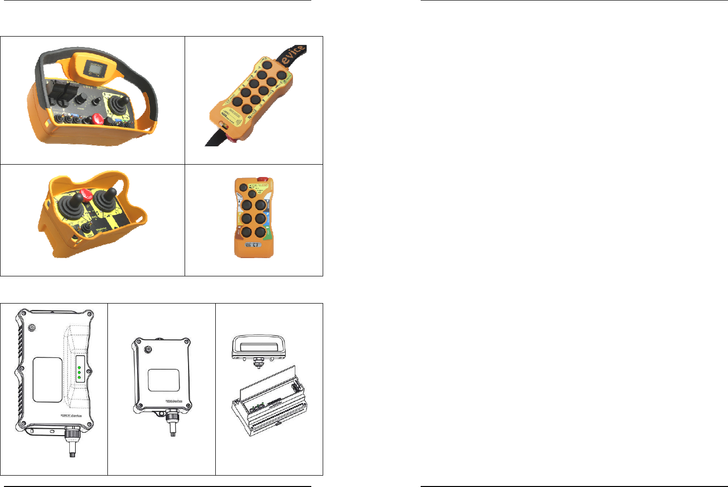
The move radio control system consists of one or more transmitter units:
GENESIS move
BRICK move
PAIL move
T
3,5,7
move
and of one or more receiver units:
RUBYBOX move
ECOBOX move
DIN move
User Manual
version 3.2
Move series radiocontrols
mod.
GENESIS, PAIL, BRICK
and
T
April 2016
4
REM
device
®
- ITALY
How TO USE the DEVICE CORRECTLY and SAFELY
The remote control has been designed strictly for use by qualified
operators only, who are required to first read the instructions on how to
use the device and comply with the safety standards prescribed by the law
in the area where work is carried out.
REMdevice shall not be liable for any bodily injury or damage to property
resulting from:
• misuse or inexpert use of the device
• incorrect wiring or electrical connections
• tampering
• changes to the radiocontrol's design features
• replacement of parts with non-original spare parts
• failure to perform maintenance
• failure to replace worn, faulty or defective parts
• the device being used with its intrinsic safety features disabled or
its original features altered in any way.
Warning: This device works using radio signals; it can operate the
machinery it is connected to even if barriers are blocking its line of sight,
such as brick walls, metal or wooden panels, other machinery, equipment,
buildings, vehicles; it is important operators exercise the utmost care when
activating the controls in order to avoid uncontrolled movements.
Activating the radiocontrol
• Stand with the transmitter unit so that there is a perfectly clear
full line of sight between it and the machinery
• do not linger under overhead loads
• do not operate from an unstable position
• take proper note of the control's identification plates located next
to each button or actuator
• do not press any button or actuator if you do not know exactly
what it does
Transmitter units
Transmitter units are made so as to comply with the control functions of
the machine they control. The figures shown are generic.
For your model, please refer to the datasheet attached to this manual.
User Manual
version 3.2
Move series radiocontrols
mod.
GENESIS, PAIL, BRICK
and
T
April 2016
REM
device
®
- ITALY 5
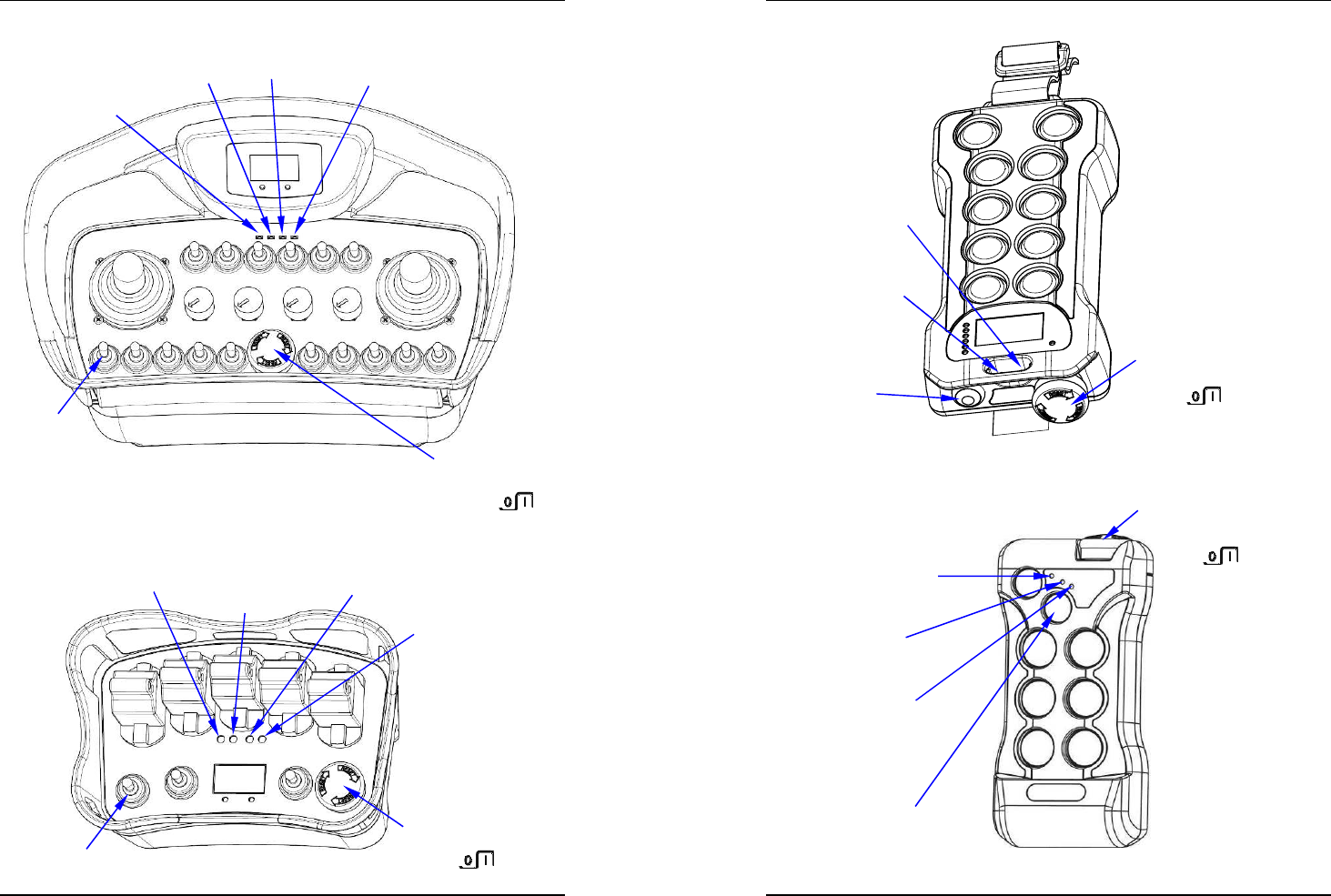
GENESIS move transmitter unit
PAIL move transmitter unit
––
GREEN LED
(ON)
RED LED
(BATT)
EMERGENCY STOP
BUTTON
START
LEVER
LED
F1
LED
F2
RED LED
(BATT)
GREEN LED
(ON)
START
LEVER
LED
F2
LED
F1
EMERGENCY STOP
BUTTON
Figure 1 – GENESIS
Figure 1 – PAIL
User Manual
version 3.2
Move series radiocontrols
mod.
GENESIS, PAIL, BRICK
and
T
April 2016
6
REM
device
®
- ITALY
BRICK move transmitter unit
T move transmitter unit
Figure 1 – BRICK
Figure 1
–
T
START
BUTTON
RED LED
(BATT)
GREEN LED
(ON)
EMERGENCY STOP
BUTTON
LED F1
START
BUTTON
GREEN LED
(ON)
RED LED
(BATT)
EMERGENCY STOP
BUTTON
User Manual
version 3.2
Move series radiocontrols
mod.
GENESIS, PAIL, BRICK
and
T
April 2016
REM
device
®
- ITALY 7
Switching on, Activation, Use, Automatic shutdown
Switching on
If not otherwise stated in the datasheet, the mushroom EMERGENCY STOP
BUTTON is used to switch the transmitter on and off. To switch on,
rotate and disconnect the mushroom EMERGENCY STOP BUTTON
Check that the GREEN LED (ON) flashes (just once), indicating that the unit
is switched on (see Figure 1, corresponding model).
Activation
Press the START BUTTON or activate the START LEVER or turn the key to
START, depending on the model. The GREEN LED (ON) flashes quickly to
indicate that the unit has been activated.
If, on the other hand, the transmitter bleeps and the RED LED (BATT) comes
on, check no controls are on via the other buttons or actuators that
prevent activation. At the same time, the audible warning of the operating
machine can be heard (if any).
Use
Press the relevant buttons or operate the relevant control actuators for the
operation you want to perform, paying attention to how the machine
behaves.
If you experience any kind of trouble controlling the machine
(for mechanical or electrical reasons or if it is not performing
as you intended in any way), press the EMERGENCY STOP
BUTTON straight away.
Never leave the transmitter unit unattended when it is switched on, even
for just a few seconds. Always switch off the transmitter unit at the end.
Put the transmitter unit away in a safe place where it cannot be reached by
unauthorized personnel; never allow inexperienced personnel to use the
transmitter unit.
Automatic shutdown
If this function is enabled (default factory setting), the transmitter unit will
switch off automatically after approx. 4 minutes of inactivity.
To restart the unit, press the START actuator.
LAYOUT and DESCRIPTION of CONTROLS
The various models differ in terms of the number of controls available and
how they are arranged. A different appendix is associated with each
configuration (see page 27) and is an integral part of this manual.
User Manual
version 3.2
Move series radiocontrols
mod.
GENESIS, PAIL, BRICK
and
T
April 2016
8
REM
device
®
- ITALY
Note: on the GENESIS, PAIL, BRICK and T transmitters, the symbols of the
respective controls are featured on the plates on the product and/or
provided with the unit. If labels or plates other than the ones provided are
used, the symbols must match the machine's functions and movements
exactly and must comply with current regulations.
SERVICE FUNCTIONS
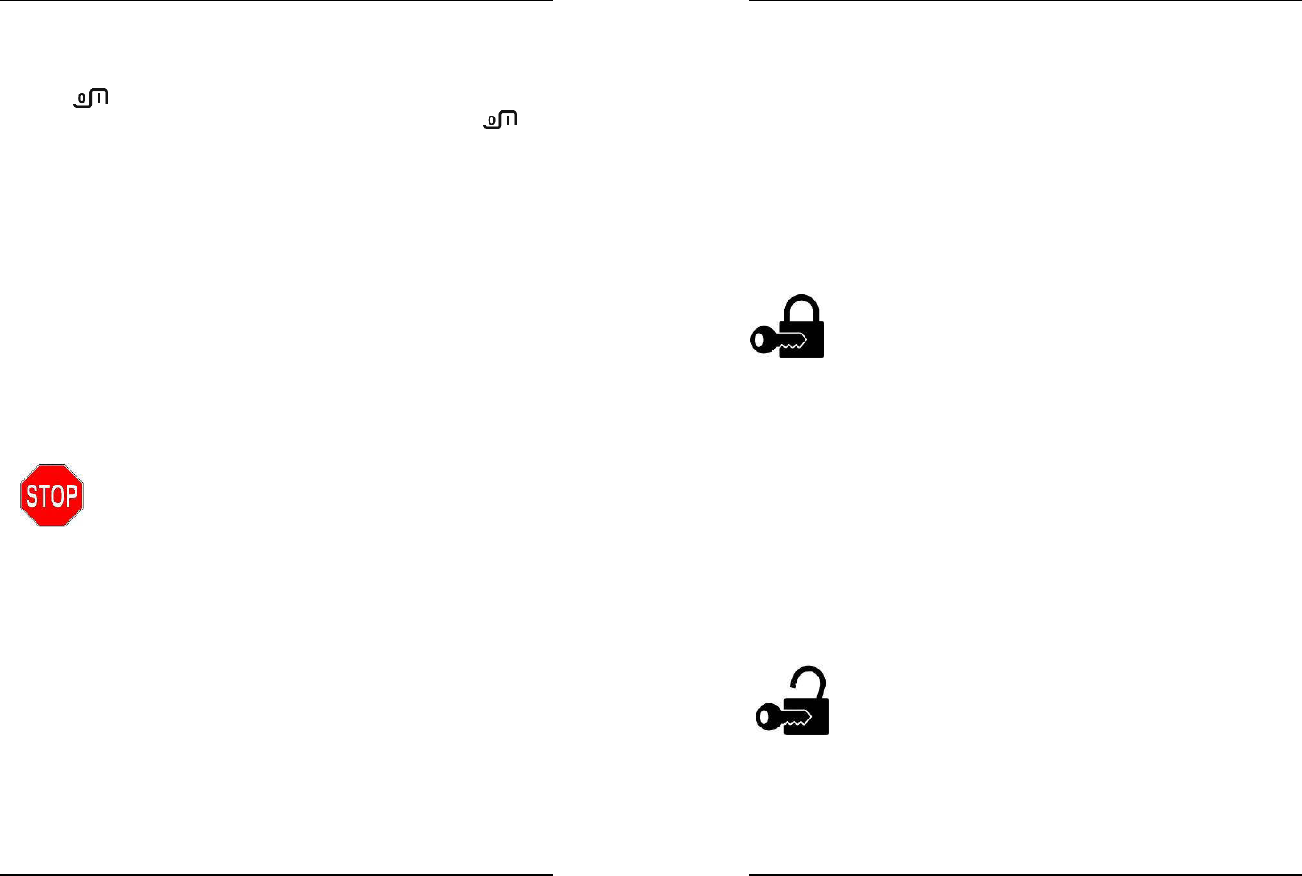
Electronic key
It is possible to prevent unauthorized staff to use the transmitter via the
function:
LOCKING and UNLOCKING the transmitter unit
In page I of the appendix (see page 27 of this manual) the actuators
assigned to this function are shown.
To lock the use of the transmitter, identify actuator Sp3 (or U1)
as specified in the appendix and follow the following
instructions:
a) power up the transmitter using the mushroom EMERGENCY STOP
BUTTON (or using the key selector, where applicable);
b) operate Sp3 (or U1) and operate the START at the same time;
keep on and count 5 beeps and flashes of the F1 LED (if applicable);
after exactly 5 beeps and flashes, release the START and Sp3 (or U1);
c) the GREEN LED (ON) will produce a long flash accompanied by a beep to
confirm that the procedure has been performed correctly.
If the procedure is not performed in this exact sequence or the controls are
held any longer, the operation will be aborted and you will need to repeat
the sequence from the beginning.
If you attempt to activate the transmitter following this operation, the
indicator lights (LEDs) will flash in turn and the transmitter unit's audible
alarm will sound (ring).
To unlock the transmitter, repeat the sequence.
If the transmitter is locked out, you will hear a long ring; if the
transmitter is unlocked, it will play a short melody.
On models with a display, the count will come up on the
display.
User Manual
version 3.2
Move series radiocontrols
mod.
GENESIS, PAIL, BRICK
and
T
April 2016
REM
device
®
- ITALY 9
TWIN auxiliary transmitter unit
TWIN systems are constituted by two transmitting units: a main and an
auxiliary. To use the system correctly:
o switch on the operating or lifting machine powering the receiver unit;
o switch on one of the two transmitters provided (primary or auxiliary)
and send the START command for approx. 10 seconds.
Once the receiver (RUBYBOX move or ECOBOX move) recognizes the
transmitter, it starts the machine, which sounds:
• ONCE (primary transmitter);
• THREE TIMES (auxiliary transmitter).
From now on, the machine can be controlled only by this transmitter until
power to the receiver unit (RUBYBOX move, ECOBOX move or DIN move) is
cut off or until the FREE command (described in the next paragraph) is
activated.
The other transmitter unit will never be able to take
control of the machine.
The Twin system complies with the EN 60204-32
standard (Safety of machinery) and does not allow
using the two transmitters simultaneously.
There are available two different ways to transfer the machine control
from one transmitter unit to another:
1) Activate the FREE function (as described in the following paragraph)
2) Turn the receiver unit off and on again after a few seconds (normally
the receiver unit is powered by the operating machine: in that case you
may power off and on again after a few seconds directly the machine).
ATTENTION: The machinery may lose power for reasons outside the
operator's control.
In this case, it is possible for a second operator with one of
the two transmitters to take control of the machine if he
happens to press the START button when power is resumed.
The different audible alarm sounds to warn the operators.
User Manual
version 3.2
Move series radiocontrols
mod.
GENESIS, PAIL, BRICK
and
T
April 2016
10
REM
device
®
- ITALY
FREE function
Only the unit controlling the machine can perform the FREE function that
is freeing the receiver to accept control of the other unit.
In page I of the appendix (see page 23 of this manual) the actuators
assigned to this function are shown.
To carry out the FREE command, identify the Sp4 (or D1) actuator
as specified in the appendix and follow the following procedure:
a) power up the transmitter using the mushroom EMERGENCY STOP
BUTTON (or using the key selector, where applicable);
b) operate Sp4 (or D1) and operate the START at the same time;
keep that position, paying attention that the beep and the F1 LED (if
any) are activated only once;
after just one flash (or beep), release the START and Sp4 (or D1);
c) the GREEN LED (ON) will produce a long flash accompanied by a short
melody to confirm that the procedure has been performed correctly.
If the procedure is not performed in this exact sequence or the controls are
held any longer, the operation will be aborted and you will need to repeat
the sequence from the beginning.
In case of error, the LEDs will flash alternately and the transmitter will
sound.
On models with a display, all stages are shown on the display and the
message "FREE" comes up to confirm the operation.
CHANGING transmitter FREQUENCY
There is no need to open either the transmitter unit or receiver unit to
change frequency. Locate actuator Sp4 (or lever D1, as specified in greater
detail on page I of the appendix on page 19 of this manual) and proceed as
follows:
a) power up the transmitter using the mushroom EMERGENCY STOP
BUTTON (or using the key selector, where applicable);
b) operate Sp4 (or D1) and operate the START at the same time;
keep on and count 5 beeps and flashes of the F1 LED (if applicable, on
the left);
after exactly 5 beeps and flashes, release START and Sp4 or D1;
c) the Green LED flashes accompanied by a short melody to confirm that
you have entered the band/frequency change menu;
d) activate Sp4 or D1 again together with START; keep on and count 3
beeps and flashes of the F1 LED (if any, on the left); after exactly 3
beeps and flashes, release START and Sp4 or D1;
User Manual
version 3.2
Move series radiocontrols
mod.
GENESIS, PAIL, BRICK
and
T
April 2016
REM
device
®
- ITALY 11
e) the Green LED flashes accompanied by a short melody to confirm that
you have entered the menu via which you can change the channel.
If you stay in state b or d for anything other than the stated time, the
operation is aborted and you will need to repeat the sequence from the
beginning.
On models with a display, the display will show the count, the number of
the set channel and advise you that you have entered the various menus.
From the channel change menu, you can:
• Activate Sp4 or D1 to get to the CHANNEL - function (unit);
• Activate Sp3 or U1 to get to the CHANNEL + function (unit);
• Activate START + Sp4 or D1 to get to the
CHANNEL -10 function (tens);
• Activate START + Sp3 or U1 to get to the
CHANNEL +10 function (tens);
• Once you have set the value you want for the frequency, press the
EMERGENCY STOP BUTTON and reset it;
• Hold the START button down for a few seconds and keep holding it
down until the machine starts.
The set channel is shown with the tens first (number of times the red LED
flashes) and then the units (number of times the green LED flashes).
The frequency band to be set varies depending on the laws and
standards in the country where the product is due to be used.
In order to operate, the radio control system with the remote-controlled
machine, must respect the laws and the regulations in the country where
it is used.
REMdevice S.r.L can not be held responsible if the radio controls are set to
prohibit frequencies in the country of use.
User Manual
version 3.2
Move series radiocontrols
mod.
GENESIS, PAIL, BRICK
and
T
April 2016
12
REM
device
®
- ITALY
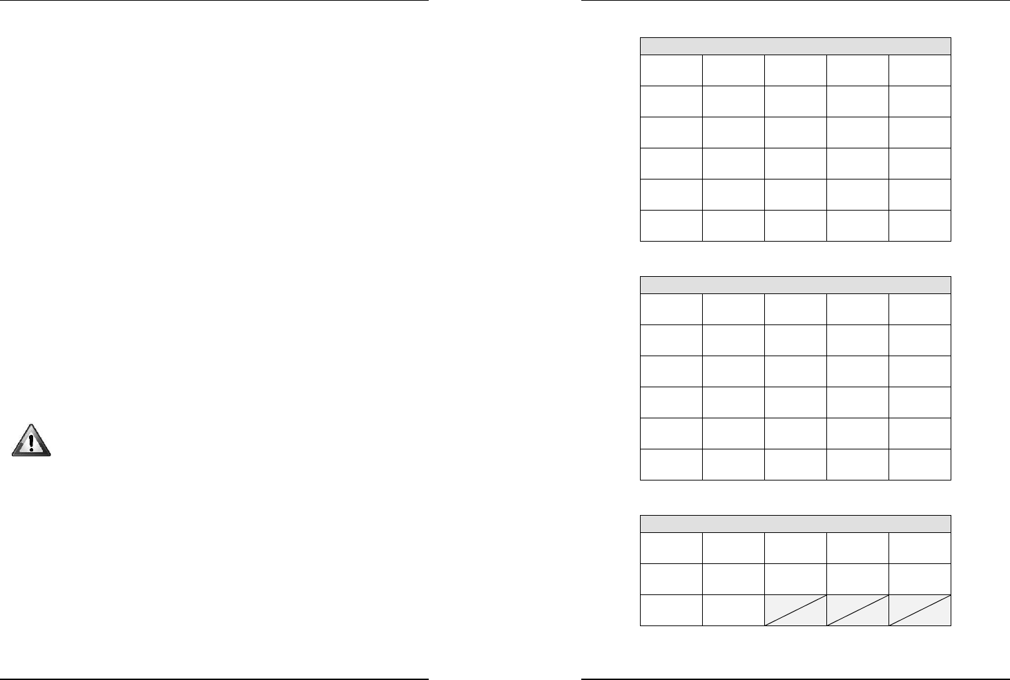
Models: EC
Band 433.050 – 433.790 MHz
CH1
433,0625
CH2
433,0875
CH3
433,1125
CH4
433,1375
CH5
433,1625
CH6
433,1875
CH7
433,2125
CH8
433,2375
CH9
433,2625
CH10
433,2875
CH11
433,3125
CH12
433,3375
CH13
433,3625
CH14
433,3875
CH15
433,4125
CH16
433,4375
CH17
433,4625
CH18
433,4875
CH19
433,5125
CH20
433,5375
CH21
433,5625
CH22
433,5875
CH23
433,6125
CH24
433,6375
CH25
433,6625
CH26
433,6875
CH27
433,7125
CH28
433,7375
CH29
433,7625
CH30
433,7875
Models: EC (…continues)
Band 434.050 – 434.790 MHz
CH31
434,0625
CH32
434,0875
CH33
434,1125
CH34
434,1375
CH35
434,1625
CH36
434,1875
CH37
434,2125
CH38
434,2375
CH39
434,2625
CH40
434,2875
CH41
434,3125
CH42
434,3375
CH43
434,3625
CH44
434,3875
CH45
434,4125
CH46
434,4375
CH47
434,4625
CH48
434,4875
CH49
434,5125
CH50
434,5375
CH51
434,5625
CH52
434,5875
CH53
434,6125
CH54
434,6375
CH55
434,6625
CH56
434,6875
CH57
434,7125
CH58
434,7375
CH59
434,7625
CH60
434,7875
Models: EC (…continues)
Band 869.700 – 870.000 MHz
CH61
869,7125
CH62
869,7375
CH63
869,7625
CH64
869,7875
CH65
869,8125
CH66
869,8375
CH67
869,8625
CH68
869,8875
CH69
869,9125
CH70
869,9375
CH71
869,9625
CH72
869,9875
User Manual
version 3.2
Move series radiocontrols
mod.
GENESIS, PAIL, BRICK
and
T
April 2016
REM
device
®
- ITALY 13
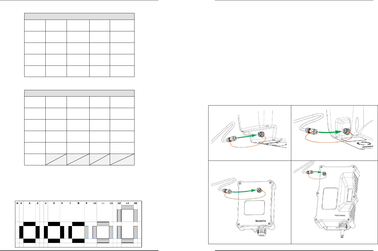
Models: FCC-IC
Band 902.5 – 915 MHz
CH1
902,5
CH2
903,0
CH3
903,5
CH4
904,0
CH5
904,5
CH6
905,0
CH7
905,5
CH8
906,0
CH9
906,5
CH10
907,0
CH31
907,5
CH12
908,0
CH13
908,5
CH14
909,0
CH15
909,5
CH16
910,0
CH17
910,5
CH18
911,0
CH19
911,5
CH20
912,0
CH21
912,5
CH22
913,0
CH23
913,5
CH24
914,0
CH25
914,5
Models: FCC-IC (…continues)
Band 915.0 – 927.5 MHz
CH26
915,0
CH27
915,5
CH28
916,0
CH29
916,5
CH30
917,0
CH31
917,5
CH32
918,0
CH33
918,5
CH34
919,0
CH35
919,5
CH36
920,0
CH37
920,5
CH38
921,0
CH39
921,5
CH40
922,0
CH41
922,5
CH42
923,0
CH43
923,5
CH44
924,0
CH45
924,5
CH46
925,0
CH47
925,5
CH48
926,0
CH49
926,5
CH50
927,0
CH51
927,5
Signalling the signal level received
Available only for models with the display option (GENESIS, PAIL and
BRICK), reporting shows the signal intensity that the base unit receives the
transmitter with and takes place through 15 bars that light up in sequence.
User Manual
version 3.2
Move series radiocontrols
mod.
GENESIS, PAIL, BRICK
and
T
April 2016
14
REM
device
®
- ITALY
To activate this function:
a) power up the transmitter using the mushroom EMERGENCY STOP
BUTTON (or using the key selector, where applicable);
b) activate Sp3 or U1 together with START; keep on and count 2 beeps
and flashes of the F1 LED (if any);
If no signalling takes place, "FAIL" is displayed.
Wired control option
The wired control connection is an option available only for transmitters
GENESIS and PAIL with receivers ECOBOX and RUBYBOX.
Activating the wired control
• Switch off both the transmitter (GENESIS or PAIL) and receiver (ECOBOX
or RUBYBOX).
• Remove the protection caps from the connectors.
• Connect the cable supplied paying attention to the white mark on the
connectors.
GENESIS transmitter unit
PAIL transmitter unit
ECOBOX receiver unit
RUBYBOX receiver unit
User Manual
version 3.2
Move series radiocontrols
mod.
GENESIS, PAIL, BRICK
and
T
April 2016
REM
device
®
- ITALY 15
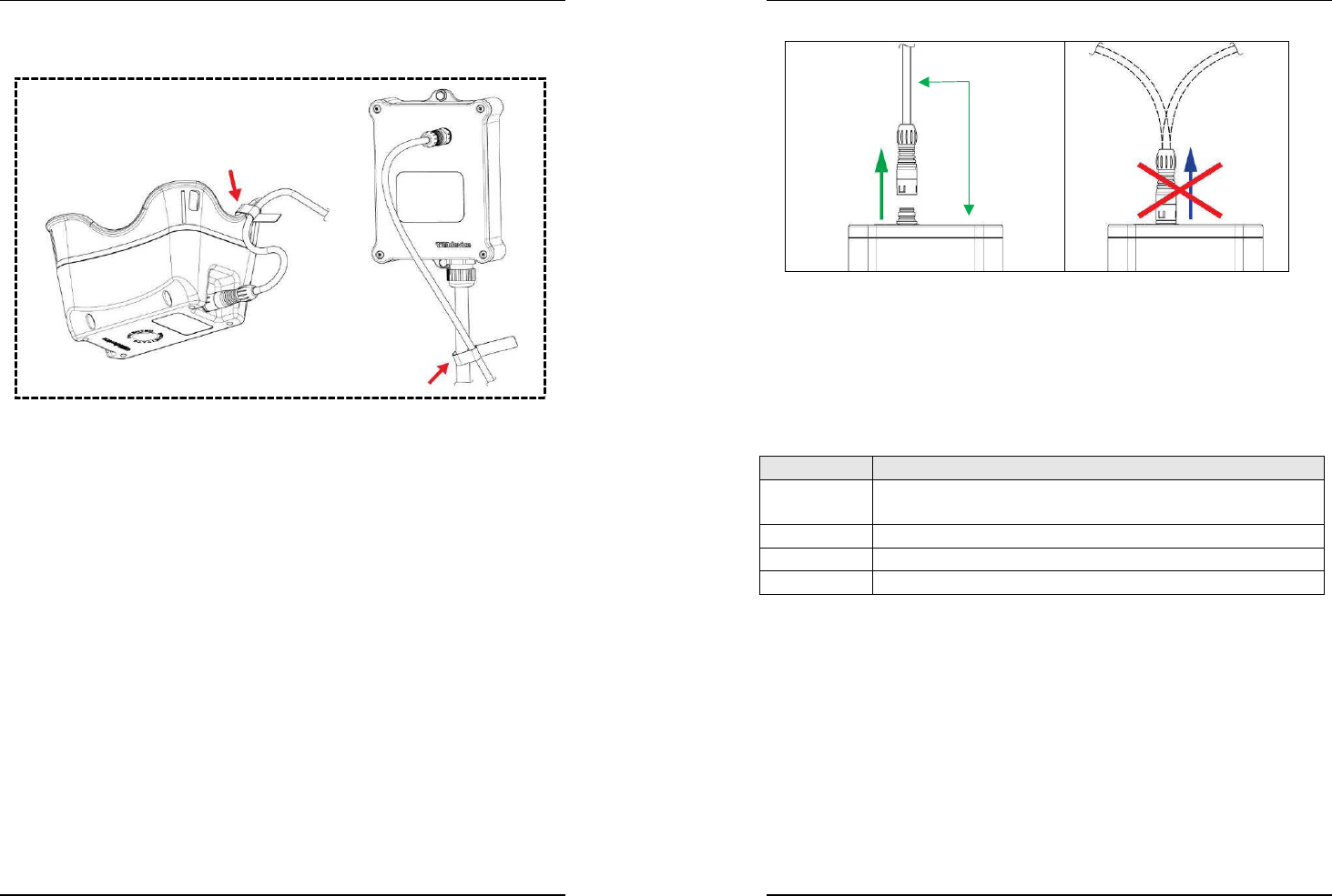
• Fix the cable using the Velcro strap supplied:
o on the transmitter handle
o on the receiver output cable
E xample of the fixed cable on:
PAIL transmitter unit
ECOBOX receiver unit
• Power the receiver and start the transmitter.
Wired control operation
When the wired control is working, radio transmission is disabled and data
is transmitted via the wire in both directions (control and data feedback
functions) as per normal operation.
Supply of the transmitter takes place via the power cable that recharges
the internal accumulators too.
Deactivating the wired control
• Switch off both the transmitter (GENESIS or PAIL) and receiver (ECOBOX
or RUBYBOX).
• Disconnect the cable supplied removing the Velcro straps.
• Reposition the protection caps on the connectors.
• Power the receiver and start the transmitter.
WARNING:
Pull the plugs with the cable perpendicular to the socket. If the cable is
bent in any direction, the plug does not separate from the socket!
(See the figure on the next page)
User Manual
version 3.2
Move series radiocontrols
mod.
GENESIS, PAIL, BRICK
and
T
April 2016
16
REM
device
®
- ITALY
MAINTENANCE
Transmitter supply
The transmitter supply varies according to the models and version
purchased.
Model Power supply types
GENESIS Internal accumulators with induction recharge or
rechargeable removable battery
PAIL Internal accumulators with induction recharge
BRICK Internal accumulators with induction recharge
T
3,5,7
Long-life non-rechargeable internal lithium battery
90°
User Manual
version 3.2
Move series radiocontrols
mod.
GENESIS, PAIL, BRICK
and
T
April 2016
REM
device
®
- ITALY 17
Recharging the induction accumulators
In the GENESIS, PAIL and BRICK models, the accumulators are housed
inside the transmitter device and are recharged using an exclusive
patented electromagnetic induction system involving no metal electrical
contacts or connecting cables.
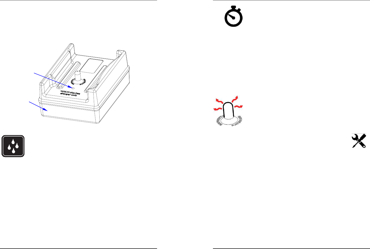
ATTENTION: the contactless charger the system comes with
must be located in a safe, dry place out of direct sunlight and
sheltered from rain; it must be plugged into the mains so that
the outlet is easy to reach at all times.
The transmitter shows the accumulator discharge limit value has been
reached when the GREEN LED (ON), the RED LED (BATT) and a long sound
are activated all at the same time. Recharge the batteries as soon as
possible:
• check that the (ON) LED is lit on the charger (see Figure 2 on page 9), (it
means it is being powered correctly);
• switch the transmitter off as described above;
• place the transmitter in the appropriate housing on the contactless
recharge unit, paying attention the peg in the centre of the recharge
base enters the hole in the bottom of the transmitter;
• if ON, the transmitter automatically deactivates when resting on the
recharge base;
CONTACTLESS
RECHARGE
UNIT
LED
(ON)
Figure 2
User Manual
version 3.2
Move series radiocontrols
mod.
GENESIS, PAIL, BRICK
and
T
April 2016
18
REM
device
®
- ITALY
the RED LED (BATT) on the transmitter unit flashes to
indicate that the accumulators are being charged properly
recharging is controlled electronically:
the recharge time is controlled automatically
• when the RED LED (BATT) on the transmitter unit is steadily lit, it means
the batteries have finished charging.
With new and fully charged batteries, the transmitter unit has a runtime
(for continuous duty) of around 30 hours at 20°C.
Under normal operating conditions, you will only need to charge the
batteries once a week (during the weekend, for example).
The electronic charge status control means you can leave the device on the
charger base for long periods of time without doing any damage to the
batteries.
It is normal for the peg sticking out of the charger and the
hollow on the underside of the transmitter unit to heat up
while the batteries are charging.
If the accumulators are completely discharged but
efficient, 30 minutes' recharge time will be enough to
guarantee the radio control operation for 8 hours.
Do NOT open the charger to attempt repairs: if there is a fault,
use the services of authorized personnel or contact REMdevice
directly.
Unplug the charger when it is not in use.
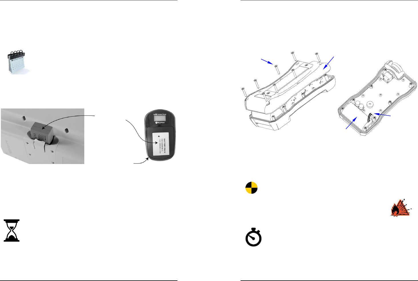
GENESIS transmitter with removable battery
The innovative 24/7 non-stop system guarantees continuous operation also
during the replacement of the removable external battery.
The radio control is fitted with two external and a group of internal
batteries. The external removable battery gives about 20 hours' operation
autonomy, while the internal group gives autonomy for 1.5 hours.
Therefore, the internal group allows the unit to work without the
removable battery while this recharges. The removable battery can then be
replaced when the RED LED (BATT) lights up, without interrupting the radio
control operation.
User Manual
version 3.2
Move series radiocontrols
mod.
GENESIS, PAIL, BRICK
and
T
April 2016
REM
device
®
- ITALY 19
Indications
The RED LED (BATT) on the transmitter flashes when:
• the external battery is low
• the external battery has been removed or reinserted incorrectly
• the contacts of the external battery are dirty, oxidized or damaged
NOTE
This happens also when the radio control is OFF and for
about 20 days, that is until the internal group is fully
discharged.
If the internal group is completely discharged, the removable external
battery must be inserted for the whole time required for the recharge;
during this time the radio control can anyway be used.
For further information on the Universal Charger, check the Instruction
Manual supplied with this product.
Attention: this charger is NOT waterproof; keep it in a cool and dry place
and recharge at ambient temperature.
The external (removable) battery lasts ≈ 22 hours at
20°C
The internal battery lasts: ≈ 1 hour at
20°C
The charge of the internal battery is sufficient to completely
recharge and replace the external battery.
UNIVERSAL
CHARGER for the
EXTERNAL BATTERY
(REMOVABLE)
EXTERNAL
BATTERY
(REMOVABLE)
User Manual
version 3.2
Move series radiocontrols
mod.
GENESIS, PAIL, BRICK
and
T
April 2016
20
REM
device
®
- ITALY
T transmitter: replacing the lithium battery
The battery is inside the transmitter: to replace it, it is necessary to open
the unit. This operation must be carried out in a clean place, with no
humidity and only by specialized personnel, authorized by REMdevice.
• Remove the 8 screws and open the transmitter lid
• Remove the connector and replace the battery with a new one
• Use the sticker applied to the battery body peeling off the protective
film and removing the residues of the old adhesive.
• Before closing the keypad, be careful in folding the red and black
wires back against the battery and prevent them from being crushed
while closing.
Strong shocks to the transmitter and its battery can permanently
damage the battery.
Risk of fire, explosion and serious burns.
The lithium battery is not rechargeable: do not dismantle, recharge,
apply voltage, short-circuit, expose to high temperatures or flames,
do not burn or immerse in water.
If the unit is not used for over 3 months, proceed to "awake"
the battery by repeating the transmitter's START procedure
until stabilized, that is until the transmitter is stabilized and
remains ON without showing any error of low battery. The operation
normally lasts a few minutes.
No. 8
LOCKING
SCREWS
LID
NON-RECHARGEABLE
BATTERY
BATTERY
CONNECTOR
User Manual
version 3.2
Move series radiocontrols
mod.
GENESIS, PAIL, BRICK
and
T
April 2016
REM
device
®
- ITALY 21
The life expectancy of the battery can be reduced if subjected to extreme
temperatures. Batteries must be stored in cool, clean and ventilated rooms
with a temperature of between 10°C and 30°C.
If batteries are stored for over 8 years they might experience a loss of
performance.
Spent batteries must not be disposed of in the environment or together with the
normal domestic waste. Batteries must be disposed of in compliance with local
regulations, using the waste disposal service available in the area.
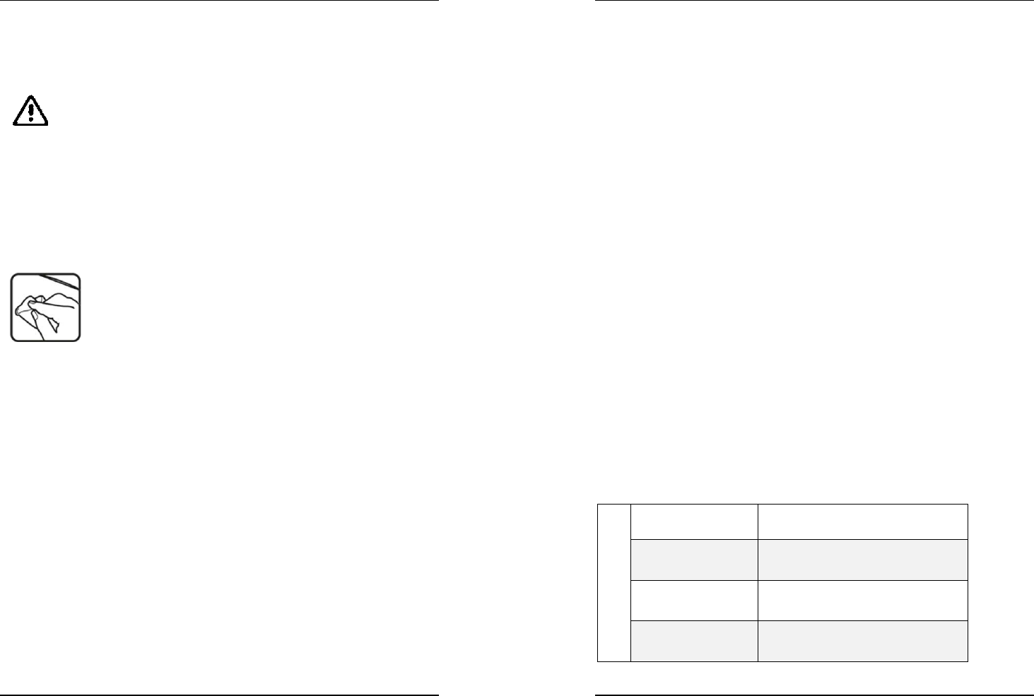
Keeping the radio control system in proper working order
Preventive maintenance and routine checks
Clean the transmitter unit at regular intervals to stop sediment building up
and becoming extremely hard to remove later on and/or obscuring graphic
symbols showing what functions are assigned to the control buttons.
Should symbols become illegible or come off, you must replace them with
new labels.
In induction recharge models, clean the cavity at the
bottom of the units periodically to prevent debris build-up.
Do not use solvents to clean the devices. Do not immerse
the transmitter unit in water.
Check that the transmitter unit's seal is perfectly
watertight, check for cracks in the housing and make sure the rubber on
buttons or control actuators is not damaged in any way. The ingress of
liquid can seriously damage or compromise the proper operation of the
electrical circuits inside the radio control.
Non-routine maintenance and any repairs needed must be carried out only
by specialist personnel authorized by REMdevice.
Above all, replacing accumulators with unsuitable parts can result in a risk
of explosion.
Checking that the EMERGENCY STOP BUTTON and all
functions are working properly
Press the EMERGENCY STOP BUTTON (see Figure 1) and check the radio
control has switched off and deactivated.
To carry on with the testing procedure, reset the EMERGENCY STOP
BUTTON by turning it roughly a ¼ turn until it clicks, then activate the
START control on the transmitter unit again.
Press a button or operate a machine control actuator associated with a
movement and, keeping it held down, press the EMERGENCY STOP
BUTTON at the same time: the machine must stop immediately!
User Manual
version 3.2
Move series radiocontrols
mod.
GENESIS, PAIL, BRICK
and
T
April 2016
22
REM
device
®
- ITALY
Reset the EMERGENCY STOP BUTTON to continue.
Once you have reactivated the transmitter unit, press one button or
actuator at a time and check that the machine performs the operation
indicated by the relevant symbol.
NEVER use the device if the EMERGENCY STOP BUTTON is not in working
order. This pushbutton has to be working properly to ensure that all
machine operations are stopped immediately and the remote control
system is disabled. If this pushbutton is not in perfect working order, or
even if it is only partially broken, system safety is compromised, meaning
the unit is no longer complying with the regulations and operators are
exposed to serious danger.
TECHNICAL SPECIFICATIONS
Conformity
All move series radio controls operating in the frequency band 433.050 -
434.790 MHz and/or 869.700 - 870 MHz comply with the essential
requirements and the other pertinent regulations set in directive R&TTE
99/5/EC. The EC declaration of conformity attached contains the list of the
harmonised regulations the radio controls comply with (as far as it is
applicable).
All the move series radio controls operating in the frequency band 902 -
928 MHz comply with the essential requirements of the following
standards:
• FCC (Federal Communication Commission) Part 15
• IC (Industry Canada) RSS-102
Transmitter Unit
BRICK move FCC ID = RTF-BRBPM6
IC number = 11555A-BRBPM6
PAIL move FCC ID = RTF-PABPM6
IC number = 11555A-PABPM6
GENESIS move FCC ID = RTF-GEGM6
IC number = 11555A-GEGM6
T move FCC ID = RTF-TTM6
IC number = 11555A- TTM6
User Manual
version 3.2
Move series radiocontrols
mod.
GENESIS, PAIL, BRICK
and
T
April 2016
REM
device
®
- ITALY 23
Receiver Unit
ECOBOX move FCC ID = RTF-EBEBM6
IC number = 11555A-EBEBM6
RUBYBOX move FCC ID = RTF-RBRBM6
IC number = 11555A-RBRBM6
DIN move FCC ID = RTF-DDM6
IC number = 11555A-DDM6
Federal Communications Commission (FCC)
This device complies with part 15 of the FCC Rules.
Operation is subject to the following two conditions:
(1) this device may not cause harmful interference, and
(2) this device must accept any interference received, including
interference that may cause undesired operation.
Any changes or modifications not expressly approved by the party
responsible for compliance could void the user’s authority to operate the
equipment.
Industry Canada (IC)
This device complies with RSS-210 of the Industry Canada Rules.
Operation is subject to the following two conditions:
(1) this device may not cause harmful interference, and
(2) this device must accept any interference received, including
interference that may cause undesired operation.
User Manual
version 3.2
Move series radiocontrols
mod.
GENESIS, PAIL, BRICK
and
T
April 2016
24
REM
device
®
- ITALY
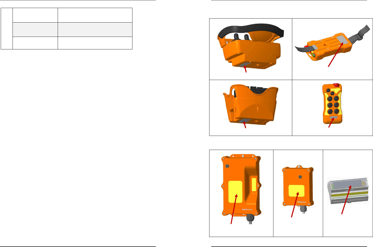
Serial Number
It appears on the ID plates of the receiver units:
GENESIS move
BRICK move
PAIL move
T
3,5,7
move
and on the receiver units:
RUBYBOX move
ECOBOX move
DIN move
User Manual
version 3.2
Move series radiocontrols
mod.
GENESIS, PAIL, BRICK
and
T
April 2016
REM
device
®
- ITALY 25
TECHNICAL SPECIFICATIONS
Full-Duplex multi-band operating frequency:
433.050 – 434.790 MHz/ Channel spacing 25kHz/ No. of channels 60
869.700 – 870.000 MHz/ Channel spacing 25kHz/ No. of channels 12
902 – 928 MHz/ Channel spacing 500kHz/ No. of channels 51
The frequency band varies depending on the standards in the
country where the product is due to be used.
Hamming code distance: > 4
Response time to commands: 20 ms min, 80 ms max
(according to the model)
Active emergency stop command response time: 20 ms
Command passive emergency response time: 1 s
Command PL Category SIL PL
(EN ISO 13849-1)
STOP e 4 3
Button/Lever (UMFS) c 2 1 SIL
(EN IEC 62061)
Joystick (UMFS) d 3 2
Range: 100 m
(≈330 ft)
Operating and storage temperature: -20°C to +70°C
(-4°F to +158°F)
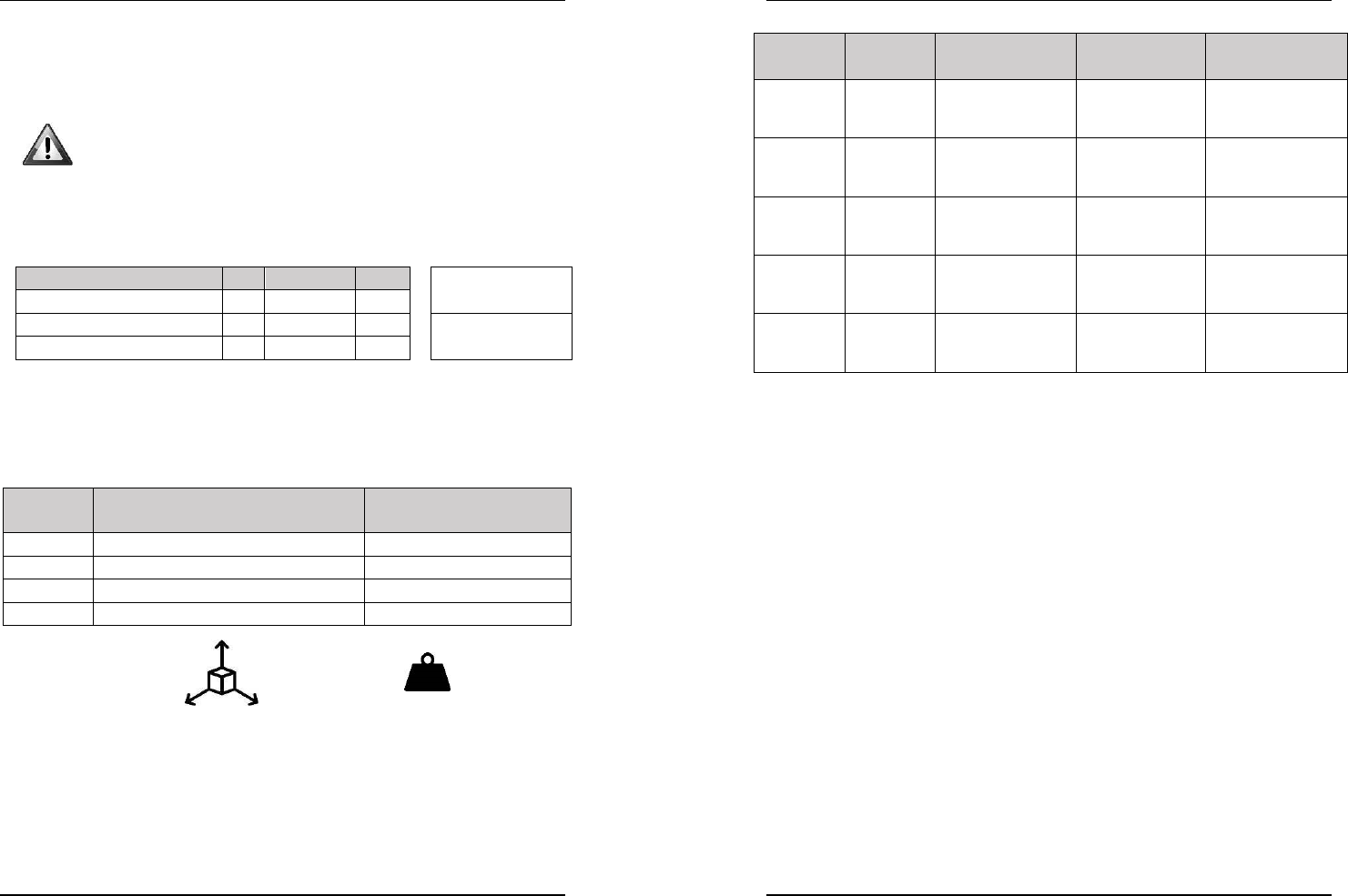
Transmitter unit
Housing protection rating: IP 65 - Material: PA6 GF
Model Dimensions [mm]
[in]
(L×H×P)
(L×W×H)
Weight [g]
[lb]
(depending on the configurations)
GENESIS 310 × 193 × 163
(12.2 × 7.6 × 6.42)
1580
3.48
PAIL 200 × 135 × 130
(7.87 × 5.31 × 5.12)
930
2.05
BRICK 97 × 210 × 44
(3.82 × 8.27 × 1.73)
470
1.04
T
3,5,7
83 × 174 × 42
(3.27 × 6.85 × 1.65)
350
0.77
User Manual
version 3.2
Move series radiocontrols
mod.
GENESIS, PAIL, BRICK
and
T
April 2016
26
REM
device
®
- ITALY
Battery low advance warning and operating autonomy at 20°C
(68°F)
Model Advance
warning time
External battery
(removable)
Internal battery
(rechargeable)
Internal battery
(not rechargeable)
GENESIS
non-stop
24/7
≈ 20 mins
≈ 22 hrs
Type: NB-7L – Li-Ion
7.4V 1000 mAh
≈ 1 hour
Type: 3 × Size AAA
1.2V Ni-MH
NOT available
GENESIS
≈ 30 mins
NOT available
≈ 30 hrs
Type: 3 × Size AA
1.2V Ni-MH
NOT available
PAIL
≈ 30 mins
NOT available
≈ 30 hrs
Type: 3 × Size AA
1.2V Ni-MH
NOT available
BRICK
≈ 30 mins
NOT available
≈ 30 hrs
Type: 3 × Size AA
1.2V Ni-MH
NOT available
T
3,5,7
≈ 30 hrs
NOT available
NOT available
≈ 1000 hrs
Type: Size D
Lithium 3.6V 19 Ah
Receiver unit
Radiofrequency receiver: Single Chip
Antenna
(according to model)
:
integrated or external
(with automatic selection)
Rp1, Rp2 relay contact capacity: 8A (DC1/AC1)
*
/ 115V
(RUBYBOX and ECOBOX)
Command relay contact capacity: 4A (DC1/AC1)
*
/ 115V
(RUBYBOX and DIN)
Stop relay contact capacity: 4A (DC1/AC1)
*
/ 115V
*
the same current can be supported also in category DC13 (inductive load)
connecting a diode in parallel to the load. For use in category AC15, we
recommend connecting a suitable RC circuit in parallel to the load for extra
voltage damping. (Ref. IEC/EN60947).
Power supply
(depending on model):
DC 12-24V ±25% or AC 24-115V ±10%
RUBYBOX move: waterproof enclosure for external installation
Material: PA6 GF V0 - Degree of protection: IP65
Dimensions: 166 × 279 × 91 mm (L×W×H)
6.53 × 10.98 × 3.58 in
ECOBOX move: waterproof enclosure for external installation
Material: PA6 GF V0 - Degree of protection: IP65
Dimensions: 129 × 178 × 51 mm (L×W×H)
2.08 × 7.01 × 2.01 in
DIN move: ModulBox housing to be fitted on DIN EN 50022 rail
Material: ABS - Degree of protection: IP20
Dimensions: 158 × 90 × 75 mm (L×W×H)
6.22 × 3.54 × 2.95 in
User Manual
version 3.2
Move series radiocontrols
mod.
GENESIS, PAIL, BRICK
and
T
April 2016
REM
device
®
- ITALY 27
NOTES:
INSERT HERE
THE ANNEXES
WITH THE
REMOTE CONTROL
SPECIFICATIONS
User Manual
version 3.2
Move series radiocontrols
mod.
GENESIS, PAIL, BRICK
and
T
April 2016
28
REM
device
®
- ITALY
WARRANTY TERMS
REMdevice covers the device with a 12-month warranty.
The date of the transport document is used as the start date of the warranty
period.
The warranty is valid only for devices affected by defects in manufacturing. The
radio control must NOT have undergone attempted repairs, been tampered
with or had parts replaced by personnel who have not been authorized by
REMdevice.
The warranty shall be voided in the event of misuse or incorrect installation.
Devices under warranty must be repaired at an authorized support centre or at
REMdevice's own facility.
Parts affected by defects in manufacturing will be replaced free of charge; this
does not include transport costs for sending and returning the device.
The warranty does not cover wear parts and batteries.
REMdevice shall not accept claims for compensation for downtime since
machinery is required to have its own manual controls.
REMdevice shall not be liable for damage, loss or theft to/of new or repaired
devices, or devices due to be repaired, while in transit.
REMdevice shall not perform work (under warranty or outside warranty) on
devices with missing serial numbers or without previous arrangements having
been made with the person requesting the work.
Manufacturer:
REMdevice
®
S.r.L
Email: info@remdevice.com
http://www.remdevice.com
REMdevice
®
S.r.L
via Alfredo Munari n. 72
36055 Nove (VI)
ITALY
TEL +39 0424 500 262
FAX +39 0424 508 631
Copyright © 2016 – REMdevice
® S.r.L
– All rights reserved.
While the information herein has been checked thoroughly for accuracy and
completeness, REMdevice disclaims liability for any errors or omissions.
REMdevice reserves the right to edit the specifications described herein at any
time without prior notice.
No part of the information herein may be reproduced, transmitted, transcribed,
stored in a retrieval system, or translated into any language in any form,
without the prior written permission of REMdevice ® S.r.L