RF Ideas HP8058X Multi Protocol RFID Reader User Manual
RF Ideas Inc Multi Protocol RFID Reader Users Manual
RF Ideas >
Contents
- 1. Users Manual
- 2. User Manual
Users Manual
pcProx® Plus, pcProx® Enroll
&
Wiegand
C
onv
er
t
er
Configuration
Utilit
y
User
Manual
99009010
Rev
A.5

Thank
You!
Congratulations on
the
purchase
of
your pcProx® Enroll, pcProx® Plus,
or
Wiegand
device(s).
RF IDeas hopes you enjoy using
the
readers as much as
we
enjoyed creating and developing
them.
Configuration
is
easy, so you
will
be able
to
quickly take advantage
of
a more secure environment
in
your business, school,
or organization.
Please call
our
Sales
department
if
you have any questions
or
are interested
in our
OEM
and
Independent Developer’s
programs.
We
look forward
to
your comments and suggestions
for our
product
line!
Please go
t
o
www.RFIDeas.com and
follow the
Suppor
t
a
Learning Center
link for
more details about
our
product
line.
We
are always discovering new applications
for our
product
line(s).
There are several
software
developer’s licensing
our
t
echnology
so
the
solution you are looking
for
may already be de
v
eloped.
Thank
you,
The RF IDeas
Staff
Need
Assistance?
Ph:
84
7.87
0
.17
23
Fx:
84
7
.
483.
1129
E:
Sales@RFIDeas.com
TechSupport@RFIDeas.com
Glossary
Of Terms
ASCII: The American Standard Code
for
Information Interchange codes represent
text in computers,
communications equipment, and
other
devices
that
use
text.
Contactless: The high frequency
13.56
MHz smart
card
t
echnology
.
FAC:
F
acilit
y
Access
Code
OEM: The
proximity
card and badge reader available
in
self-contained electronic modules
for easy
system
integration.
pcProx Contactless: The registered
RF
IDeas brand name given
to all
13.56
MHz
contactless
card
reader
products.
pcProx
Proximity:
The registered
RF
IDeas brand name given
to all
125 kHz
proximity reader
products.
Proximity:
The
low
frequency 125 kHz RFID
t
echnology
.
SDK:
Sof
t
w
ar
e
Developer’s
Kit.
Sof
t
w
ar
e
Developer’s
Kits from
RF
IDeas provide
the
high
level
command capabilities
to
integrate software applications
to our devices.
Contents
2
Thank
You!
3
Glossary
Of Terms
5
Chapter
1: The
Basics
5
Wireless Identification
Overview
6 ID
Card Reader
S
y
st
em
6
pcProx
Output
F
ormats
7
Credential Form
F
actor
s
8
Card
Compatibility
8
Reader
Configuration
P
urposes
8
pcProx Plus
&
Non-Plus Reader
Differences
9
Chapter
2:Hardware
9 What’s In
Your
P
ar
t
Number?
10
Interface
(Connectors)
11
USB Readers
and Wiegand
Converters
11
RS-232 Readers and
Converters
11
Minimum
System
R
equirements
12
Reader Set-Up
Basics
12
LED
Beeper
13
Chapter 3:
Software
13
pcProx Configuration
Utilit
y
13
Utility Overview
14
Menu Tool
bar
19
Icon Tool
bar
22
pcProx Plus
Configuration
23
Standard
Configuration
23
Connect
Tab
25 Output
Test
Area
26
Data
F
ormat
Tab
28
Delimeters
Tab
30
Timing
Tab
31
SDK
Tab
35
CHUID
Tab
45
Chapter
4:
ASCII Command
P
r
ot
oc
ol
45
ASCII
Overview
46
Connect Serial Communications
P
r
ogram
47
Command
Structure
50
Help
Command
54
Variable
Command
58
ACP Error
Codes
59
Chapter 5: Tips and
Troubleshooting
59 Troubleshooting
60
Frequently Asked
Questions
63
P
r
ecautions
63
Before You Call Technical
Support
63
Talking To The
Technician
66 Index
67 Appendix
69
Other Products and
Accessories
The
Basics
1
Wireless Identification
Overview
pcP
r
o
x®
Activated
Identification
Employers are more security conscious than ever.
More
buildings, machines, systems,
and
applications require identification information
to
gain access. RF
IDeas devices allow
the building
access cards
to
be used as a digital identifier throughout
the workplace.
Various pcProx applications
include:
•
Card
Enrollment
•
Application
log-on
•
Form
filler to
existing software
applications
•
PC/LAN Log
On
•
Cafeteria
P
ur
chases/V
ending
•
Machine
Access
•
PLC and embedded
controllers
•
Time
/
A
tt
endanc
e
Our pcProx Plus devices are easily configured
to
increase security and
r
eliabilit
y
.
Companies
using
proximity
and
/
or
contactless
t
echnology
for
building access
immediately benefit, as
their employee
identification cards can also be used
with the
pr
o
ximit
y
/
c
ontactles
s
device
for additional
authentication applications. Thus,
the majority of
deployment and enrollment costs are
quickly
recovered.
The diagram on
the
following page
is
a high level overview
of how the
reader
works.
The
reader
sends
RF signals
to the
card and
the
card sends signals back
to
send
data.
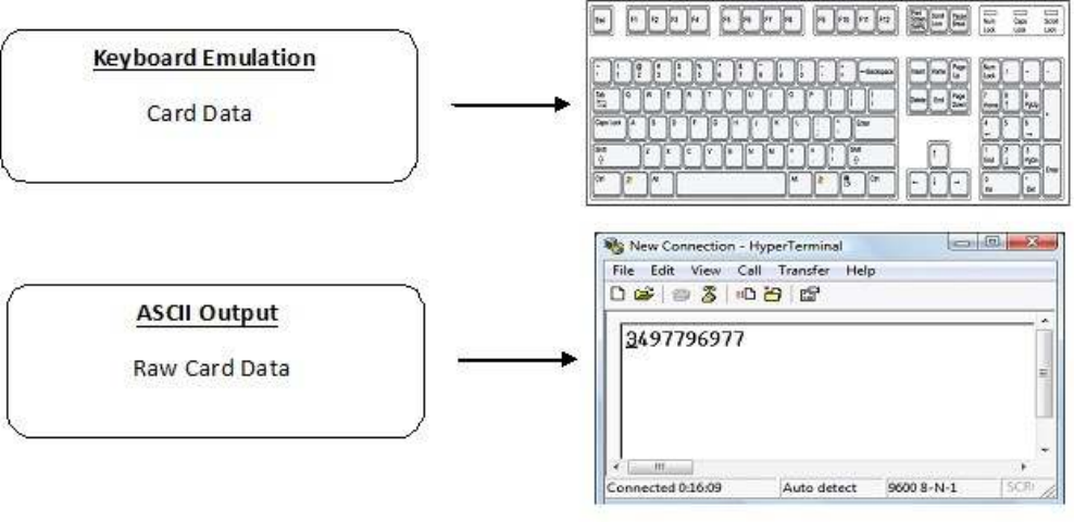
The card data
is output by
the
reader
in
keystrokes
or
ASCII characters. This card data can be configured
to
include
delimiters
to
separate
the data.
This reader can be used as a standalone system
or
seamlessly integrated
with
other software applications
using
the
optional
Sof
t
w
ar
e
Developer’s
Kit (SDK).
ID
Card Reader
S
y
st
em
Output
F
ormats
Credential Form
F
act
or
s
Credentials are inactive electronic devices
that
rely on readers
to
supply
the
required power
for
start-up
and communication. The credential
itself
,
consists
of
antennas
that
produce
proximity or
contactless frequencies.
P
r
o
ximit
y
and contactless smart card
t
echnology
cards allow users
t
o
effortlessly manage multiple applications through a single
credential.
Data: The data on access cards are a string
of
binary numbers set
with
a fixed configuration
and
length.
Frequencies:
RF
IDeas’ access control readers and credentials utilize
the
low-frequency
125
kHz
(proximity)
band and
/
or
the
high-frequency
13.56
MHz
(contactless)
band.
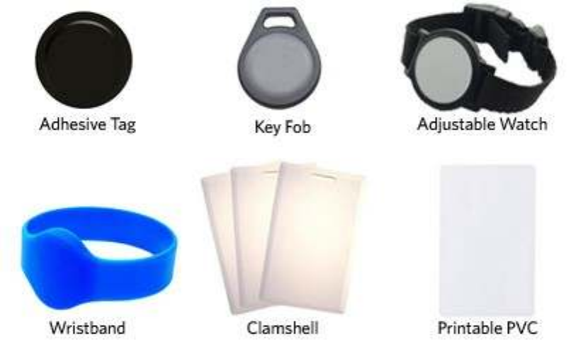
Credential Form Factors:
With
over
300 million
physical access credentials
in
use worldwide,
there
are a variety
of low
and high frequency
form
factors customers can choose
from to
meet
their
particular
needs.
The below illustrates some
of
the various
form
factors
available.
CSN: Also known as
the
Card Serial Number,
is part of the
ISO 15693 standard
for vicinity cards
operating
at the
13.56
MHz
fr
equency
.
UID: The User
ID or
User Identification, can be encoded as data on
the
card when a security key
is
needed.
Manuf
actur
er
/
V
endor
Card
Compatibility
Please go
to
www.RFIDeas.com
for
specific device
part
numbers associated
to
card
types.
Reader
Configuration
P
urposes
The method
of
encoding data on a card and transmitting data
to the
reader differs accordingly
t
o
each
t
echnology
involved.
The reader
itself is not
aware
of the
makeup
of the
card data
format or
access privileges
for the
cardholder. This information
is
only accessible through
the configuration
process
of the
reader utilizing
the
supplied
software.
The reader
is
very flexible and may need
to
be configured
in
order
to
present an exact desired
output
for the
user, such as, singling
out
FAC
or
ID, obtaining a desired base (i.e. decimal, lowercase,
upper-
case,
hexadecimal).
Differences Between pcProx Plus Reader Non-Plus
R
eader
The pcProx Plus
is
a dual frequency programmable reader
that
combines 125 kHz and 13.56
MHz
t
echnologies
into the
same reader.
It’s the
only reader
in the
industry
that
reads
two
cards
of your
choice among
35
card
t
ypes,
delivering
flexibility to
any customer struggling
with
different
card
technologies.
In
contrast
to the
pcProx Plus reader,
our
standard pcProx Enroll
proximity
and contactless
readers
function on a single frequency band, which
is
either 125 kHz
proximity or
13.56
MHz contactless.
Hardware
2
What’s In
Your
P
ar
t
Number?
All
RF
IDeas reader
part
numbers
follow
a
distinct
system
of
categorization
to
allow
for
an ease
of
differentiation between
products.
Below
is the
basic
part
number
scheme.
RDR - 6 3 8
1
A K U
Reader
Type
Frequency
Card
Type Model
Housing
Color Interface
Housing
Version
Reader Type: The reader
type distinguishes between standard
reader, OEM, c
onv
er
t
er
,
mag-stripe,
or
a
kit.
Frequency:
RF
IDeas’ access control readers are available
in
low-frequency
125 kHz
(proximity) or
high-frequency
13.56
MHz (contactless).
Card Type: The card type allows
for the
selection
of
over
35
different card
t
ypes
for reader
compatibility
(Please
visit
www.RFIDeas.com, choose a product and locate
the
P
ar
t
Numbers
tab for
specific device
part
numbers associated
to
card
types).
Housing: This option provides
the
user
to
select
the form factor
housing
for the
desired reader.
The
housings include; desk
t
op
,
wall
mount, USB dongle, PCMCIA, bare board, ExpressCard,
or custom.
(For more on
form
factors, please
visit www.RFIDeas.com)
Model
:
The model selection corresponds
to the
type
of
reader, whether
it is
a standard,
writ
er
(13.56
MHz
contactless only), playback (13.56
MHz
contactless only), SDK,
or
analyzer
.
V
er
sion
:
The version refers
to the
selection
of
either
our
standard
or
custom
build.
Housing Color: The color category simply allows
for the
selection
of
either
our
black
or pearl
housings.
(Applies only
to
desk
t
op
and
wall
mount
housings)
Int
er
f
ac
e
:
This option specifies
the
type
of
connection
for the
reader (i.e. USB, RS-232, PCMCIA,
etc).
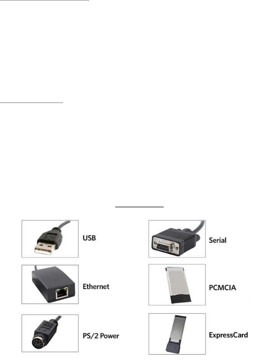
Interface
(Connectors)
C
T
ONNE
C
T
ORS
OUTPUT

USB Readers
and Wiegand
Converters
The pcProx USB keystroke device operates
in two
primary
modes:
•
USB keyboard.
It
reads
the
card data and sends
it
as keystrokes as
if the
user typed
the ID
data on a
keyboard.
•
Under
the
application programmer interface
(API)
defined
in the
pcProx SDK.
When it reads
card data,
the
active application receives
the
entire card
data.
Note:
The pcProx ExpressCard operates as a USB
r
eader
.
RS-232 Readers and
Converters
The RS-232, Ethernet,
or virtual COM port
device operates
in two
primary
modes:
1.
ASCII
output
device.
In this
mode
the
user card data
is
read and sent as a decimal
or
hexadecimal number
in
ASCII
characters.
2. API defined
in the
pcProx SDK. The device attaches
to
a computer serial
port. When it reads
card data,
the
active application receives
the
entire card
data.
Once
the
configuration settings are correctly configured and
written to
flash
memory
,
the
device
can
immediately be
deployed.
Note:
The pcProx PCMCIA operates as an RS-232
r
eader
.
Minimum
System
R
equir
ements
Minimum
S
y
s
t
em
Requirements
HARDWARE
Pentium class
PC
MEMORY 32 MB RAM
DISK 25 MB
hard disk
space
I
/O
1
available RS-232
or
USB
P
or
t
Operating
S
y
s
t
em
Any
operating system
that supports
a USB keyboard
including
Microsoft
Windows 2000®,
XP®, Vista®, 7®, Server
200
3®,
Server 2008®, Linux, Macintosh®. Can be used
for keystroke
applications
Note:
The software
does
not
perform any data validation checking. The data must be known before
it is
read
to
verify
its
v
alidit
y
.
Reader Set-Up
Basics
Plug
the
connector
into the
workstation’s
(or
available on any peripheral) open
RS-232, USB
or
Ethernet
plug.
Place
the
device next
to the
monit
or
,
beside
the
workstation,
or
where
appropriate.
The workstation should detect new hardware
for
USB
connections.
Verify the
workstation
r
ec
ogniz
es
this
connection using Device
Manager’.
Verify the
correct
COM port for
RS-232 DB9 connections using ‘Device
Manag
er
.
’
When the
software
is
installed,
it
should recognize these connections
in
order
to
configure
the
appropriate device. Once
the
device
is
configured and
written to its
flash
memory
,
these settings
will
not
have
to
be configured
again.
LED
Beeper
The desk
t
op
,
USB dongle,
wall
mount, and bare board
(OEM)
model readers are
all
equipped
with
a
light
up LED on
the front
cover. The LED
is
configurable through
the utility
software
(
See
LED
and
Beeper functions
in the
Sof
t
w
ar
e
section)
to
allow
the
device
to
produce a beep upon
light
up
of the
LED when a credential
is
detected
by the
r
eader
.
Software
3
pcProx Configuration
Utilit
y
The pcProx Configuration
Utility
provides users
with the ability to
configure
their
pcProx
Enroll,
pcProx Plus,
or
Wiegand devices
to
meet
their
needs. Through
the
configuration process,
desired
credential data
output
and access privileges
for
cardholders can be
established.
In
contrast
to the
pcProx Enroll readers,
for
which only one configuration can be programmed
into the
reader,
the utility
allows
the
pcProx Plus configuration process
to
create
two
separate
configurations
for users.
Utility Overview
Icon
Toolbar
(pg.
19)
Menu
Toolbar
(pg. 14)
pcProx Plus
C
onfiguration
Ar
ea
(pg.
18)
Standar
d
C
onfiguration
Ar
ea
(pg.
18)
Output
Test
Ar
ea

Menu Tool
Bar
The Menu Tool Bar contains
all the
basic configuration options
for the
utilit
y
.
File
The
file
menu
lists the
options
for
Opening .Hwg and Saving .Hwg
files.
Open
.Hw
g
/.Hwg+
File: Opens either a .Hwg
or
.Hwg+
file. A
.Hwg
or
.Hwg+
file
contains
all the
configuration settings
for the
reader. The
utility
comes
with
sample
.Hwg/.Hwg+ files.
Save
to
.Hwg+ File: Saves
the
configuration settings
to the
r
eader
.
What is
a
.Hwg/.Hwg+ file?
There are
two
kinds
of
configuration files. There
is
a .Hwg
file
and .Hwg+ file.
A
.Hwg
file
can only be created
with
previous pcProx application
utility ver-
sion.
A
.Hwg+
file
can only be saved using
this
new
utility
.
A
.Hwg+ can configure a
pcProx
Plus reader as
well
as a single configuration
r
eader
.
Exit: Exits
out of the
entire
utilit
y
C
onnect
The connect menu provides options
for
device
to utility connections.
Auto
Connect
to
USB on Startup: Set as
utility
default connection. Through
this
connection
the
utility
searches
for
a USB
connection on
star
tup
.
Auto
Connect
to
Serial on Startup:
With this
selection,
the utility
searches
for
any available
serial
connections on
star
tup
.
Auto
Connect
to
Ethernet on Startup:
Utility
option
to
search
for
ethernet connections on
star
tup
.
Why
use
the Auto
Connect
f
eatur
e
?
The
utlity’s
auto connect features allow users
to have
an easy auto connect through a specified
port
on
star
tup
.
Connect: This selection has
the utility
search
for
a device connection through
all
available
port
connections.
Why
use
the
Connect
f
eatur
e
?
The
utlity’s
general connect option gives users
the ability
to
connect
their
device
to the
utilit
y
,
without the
user needing
to
identify
the
devices
actual
interface connection. This feature cycles through
all
available ports
until
a device
is found.
Note:
For further information on
the
connect option, see
the
connect portion
of the Icon
Toolbar section on page 19
of this manual.

(
C
onnect
--C
ont.)
Connect
to
USB: Connects
to
current specified reader through
USB
Connect
to
Serial: Connects
to
current specified reader through
serial
Connect
to
Ethernet TCP/IP: Connects
to
current specified reader through ethernet T
C
P
/IP
Why
use
the
Connect
t
o
f
eatur
e
?
The connect
to
feature allows
the utility to
connect
to a
device through
the
specified
port
upon selection. This
is
especially helpful when users
are
switching
out
and changing devices
with
different
connections.
Disconnect: Disconnects
all
connected devices
from
every available interface connection
from the
configuration
utilit
y
.
Note:
For further information on
the
disconnect option, see
the
disconnect portion
of the
Icon Toolbar section on page 21
of this manual.
Device
Menu
The device menu
lists the
options
for
resetting,
writing
t
o
,
and reading
the
device’s data
memory
.
The
device menu options are altered depending on
the
type
of
device
that is
connected.
A single
configuration reader device has different device menu options than a
two
configuration reader
device.
Single
C
onfigur
ation Readers:
Reset
to
Factory Defaults: Resets
all
configuration parameters
to
factory
defaults.
Read Settings: Displays
the
current connected device
configuration
Write
Settings:
Writes the
current configuration settings
to the
connected
device
Note:
For more information on
the Write
Settings option, see
the Write Settings/W
rit
e
Active portion
of the
Icon Toolbar section on page 21
of this manual.
pcProx Plus
- 2
C
onfigur
ation Reader:
Reset
to
Defaults: Resets
all
configuration parameters
to
defaults. Defaults are set as
HID
Prox and RDR-758x
E
quivalent
(
c
ov
er
s
5
different card
t
ypes;
HID
iCLASS CSN, ISO
14443A
CSN, ISO 15693A CSN, MIFARE CSN, MIFARE DESFire
CSN)
Reset
to
Stored Settings: This selection allows users
to
reset
the
device
to their own
personally defined stored
settings.
Write
Stored Settings:
writes the
current configuration settings
to
stored
settings
Note:
Stored settings are defined as configuration settings created
by
a user
and
set
/
writt
en
to the
device through
the utility
as a stored
settings.
(Device
Menu--Cont.)
pcProx Plus
- 2
C
onfigur
ation Reader:
Read Active: Reads
the
current configuration. Active settings are
what
allow
the
device
t
o
function.
Write
Active:
Writes the
current configuration
to
active
settings.
Note:
For more information on
the Write
Active option, see
the Write Settings/W
rit
e
Active portion
of the
Icon Toolbar section on page 21
of this manual.
Note:
Device Menu options are altered when a
two
configuration device (pcProx
Plus
)
is
connected
to the
utilit
y
.
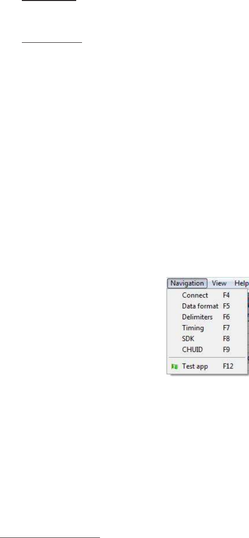
Navigation Menu
The Navigation menu gives users
the ability to
navigate
in
and
out of the utility
tabs through
the use
of hot
keys. This menu
lists the hot
key commands
for the
tabs as seen on
the
Standard
Configuration
Area (An
explanation
of
each
tab
can be found
in the
Standard Configuration Area section
of this
manual).
For example, pressing
the
F5 key on
the
keyboard
will
open
the
Data
F
ormat
tab
.
A
Test
App hot
key command
is
also available
in this list.
This command opens any
keystroking
capturing program (i.e. notepad, wordpad
etc) in
a new
windo
w
.
The Test
App
default
opening
program
is
set as
notepad.
View Menu
The view menu provides options
for
altering
the
appearance
of
certain functions
of the application
utilit
y
.
All the
options
in this
menu are set
to
appear
by default.
Show
Tooltip
Balloon: Menu option
for
displaying
or not
displaying
the tooltip
pop-up
balloon.
Note: Tooltip
balloons appear
automatically
,
or
pop up, when
the
user pauses
the mouse
pointer over a
tool or
some other
UI
element. The
tooltip
appears near
the
pointer
and
disappears when
the
user moves
the
pointer away
from the
tool,
or
simply waits
for
a
few
seconds. The
tooltip
displays descriptive information
of the
specific element
or tool that the
mouse
is
currently hovering ov
er
.
(View Menu--Cont.)
Show Text Under Toolbar Icons: Provides option
to
display
or
remove
text
under icons
in the Icon
Toolbar (For more information on
the
Icon Toolbar, see
the
Icon Toolbar section on page 19
of this
manual).
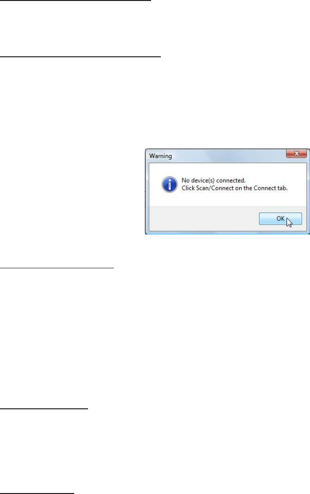
Show Pop-Up Warning Dialogues: Gives option
for
user
to
display
or
remove warning
pop-up
dialogue
boxes.
For example,
if the
Show Pop-Up Warning Dialogues option
is
selected, then a
warning
dialogue box, as seen below,
will
display on your screen. The below warning dialogue box
has
been
displayed to
alert
the
user
that the utility
has
not
detected a connected
device.
Show Confirm Dialogue: Menu option
for
displaying
y
es
/
no
confirmation dialogues before
certain
utility
operations are
completed.
For example,
if the
Show Confirm Dialogue option
is
selected, a confirmation
dialogue
window
will
appear when a user clicks
to
reset
their
device
to
factory
defaults.
Note: If the
Show Confirm Dialogue option
is not
selected,
all utility
operations
will
continue upon user selection
without the
need
for confirmation.
Beep On Warnings: Provides an audible system beep when warning are
detected.
Note: With the
Beep on Warnings option,
the
audible beeps
will
sound even
if the Show
Pop-Up Warning Dialogues option
is not selected.
Resize
W
indo
w
:
The
utility
window
is
designed
for
users
to
optionally resize,
by
making
the
window larger
or
smaller
(the
smallest resize choice
will
eliminate
the
view
of the Output Test
Area).
If
a user resizes
the utility
windo
w
,
clicking
this
Resize
Window
option
will
resize
the
window
to its
original
size.

Help
Menu
The help menu provides options
for
which users can seek
out
additional assistance using
the
utilit
y
and
/
or
device.
Read User Manual: Opens
the pdf
user manual
that is
bundled
in the
download
with the
configuration
utilit
y
.
Note:
The user manual can also be found
in the
directory folder
in
which
the configuration
utility
was
installed.
www.RFIDeas.com: This operation
will
open a new window
to the
RF IDeas
website.
Check Website
for
Sof
t
w
ar
e
Updates: Clicking
this
option
will
take users
to
a location on
the
RF
IDeas
software updates portion
of the
website, and
will
detect
what
version
of the
pcProxConfig
utility is
currently
in
use.
Any
updates
that
are available
will
be listed
for
easy
user
download.
About: This selection’s menu options
differ
when a device
is
connected
to the utility
vs.
when
there
is
no device connected.
Without
a connected device
the
about informational content
simply
displays
the utility
version.
When
a device
is
connected,
the
firmware information
is also
provided. The
RF IDeas Tech
support email and website
address are displayed
in both modes.

Icon Tool
Bar
The Icon Tool Bar contains
the
three most general configuration controls
for the
utilit
y
.
These
controls
are also found
in the
Menu Toolbar under Connect
(for
connect and disconnect) and Device
(f
or
writ
e
settings and
write active).
C
onnect
Clicking
the
Connect icon
button
commands
the utility to
search
for
a device through
all available
port connections.
Once
the utility
detects a device connection,
the
Device List pull-down menu
in the Standard
Configuration Area displays
the
interface connection, firmware and LUID information
for the con-
nected device. The model number
of the
device
will
be displayed below
the
Device List pull-down
and
the Output
Test Area
will turn from
gray
to green.
Note: More
than one device can be connected simultaneously
to the
utilit
y
.
To switch
between
devices, select
the
desired connected device
from the
Device List pull-down
menu.
Device List
P
ull-down
Menu
Device
Model
Number
(
C
onnect
--C
ont.)
If
an
attempt to
connect
to
a device
is
made and
the utility
does
not
detect a device through any
of
the
available interface connections, a
“no
devices
found”
message
will
display
in the utility’s status
bar
area.
Status
Bar

Disconnect
Clicking
the
disconnect icon
button
commands
the utility to
disconnect
from all
devices
connected
through any and
all
available
port connections.
Once
the utility
disconnects
from all
available device connections,
the
Device List pull-down
menu
and device model number are cleared
from the
Standard Configuration Area and
the Output Test
Area
will turn from
green
to
gray.
A
dditionally
,
the
status bar
will
display a “Disconnected” mes
sag
e.
Status Bar
Mes
sage
Write
Settings/Write A
ctiv
e
The
Write
Settings icon
button
prompts
the utility to write the
current defined configuration
settings
to the
device. Since
the writing
options
differ
between a single configuration device and a
t
w
o
configuration device (pcProx Plus),
the Write
Settings icon
will
change depending on whether a
single
or two
configuration device
is
connected.
When
a
two
configuration device
is
connected,
the
icon
text
will
change
to
read
“Write
Active,”
as seen
belo
w
.

pcProx Plus
Configuration
This section
is
only available
to
configure selections when a
two
configuration device (pcProx
Plus
)
is
connected
to the
utilit
y
.
Note: When
a single configuration device
is
connected
to the
utilit
y
,
the
pcProx
Plus
Configuration area
is
grayed
out
(as seen
below)
and selections
within this
area are
not possible.
The pcProx Plus Configuration area allows
for
users
to
set-up
two
different configurations
for their
device. The configurations could be either one
125 kHz and one 13.56 MHz,
or two
125 kHz and
t
w
o
13.56
MHz. The configurations can also be
of the
same card
t
ype.
The device
is
set
with two default
configuration settings,
the HID
Prox and RDR-758x
E
quivalent
(
c
ov
er
s
5
different card
t
ypes;
HID
iCLASS CSN, ISO 14443A CSN, ISO 15693A CSN, MIFARE CSN, MIFARE DESFire
CSN).
Note: If
configuring
the
system
for HID 26 bit
and
HID 35 bit,
remember
to
set one
configuration
to
read only
26 bits
and
the
other configuration
to
read only
35 bits.
Configuration
#
(Number)
High
P
riorit
y
Card
T
ype
Dr
op-Do
wn
Configuration
#
(Number): This option provides
the ability to
switch between
c
onfigur
ations.
Users can set and
edit
settings
for two
separate configurations quickly and easily
.
Card Type Drop-Down Menu:
As
stated above,
the
device
is
set
with two
default
configuration
settings,
the HID
Prox and RDR-758x
E
quiv
alent.
This drop-down menu lets users choose
the
desired card
type
for their own
configuration settings.
Each
configuration has
the ability to have
separate card
types.
High
P
riorit
y
:
Provides a pcProx Plus user
the ability to
give a certain configuration a
higher
priority
than another. This is useful when
the
user has a population
of
cards consisting
of a
combination
of
13.56MHz/125kHz cards as
well
as single-technology cards, and one
of
those
is
preferred over
the
other
.
The High
P
riorit
y
bit
increases
the time it
takes
to
read
the
card.
When the
High
priority bit is set,
the
reader
will try to
read
that
card type
10 times before switching
to the
other
configuration.

Standard
Configuration
This Standard Configuration area provides
all the
options and details necessary
to
configure
a
connected
device.
USB
Serial:
RS-
232
and
V
ir
tual
CO
M
Ethernet
Connect
Tab
The connect
tab
offers
the
various ways a device can connect
to the
configuration
utilit
y
.
The
different selections allow
the
user
to
choose
the
connection type
for the
specific logical protocol
of
their
r
eader
.
Note:
Only one connection type
at
a
time will
be
shown.
USB: Make
this
selection
if the
connected device has a
USB
logical protocol. The
utility will then
proceed
to
scan any available USB bus
for
connected
devices.
Serial: RS-232 and
Virtual COM
Ports: This option provides devices
that
are RS-232
or Virtual
COM port
logical protocols
to
connect
to the
utilit
y
.
This section scans
for
RS-232, physical
COM
port
devices,
virtual COM port
devices, including
USB,
CDC and PCMCIA
devices.
When
making
this
selection,
the
lower and upper
limits of the COM
ports
to
scan need
to be
set. The
port
values range
from
1
to
256. The default
COM
ports are set
at
1
thru 8.
Default
1..8:
This option sets
the COM port
values back
to the
default
of
1 and
8.
Note:
Serial devices may slow when scanning a wide
port range.
(
C
onnect
Tab--Cont.)
Ethernet (Local IP 10.10.10.65): Connects
to
an Ethernet reader
at the
given IP address and
open
a TCP/IP on
the
given port. The
first,
second, third, and
fourth
byte
of the
TCP/IP address need
t
o
be entered
for the
interface
to
connect
to the
reader. The IP
port
number
will
also be
required.
P
or
t
Option:
Allows for
changing
the port
location.
Xport port
location needs
to
match
this
number
Note:
Ports below 1024 are
for
system use
only
.
Find Next IP Button: Looks
for
other readers on
the
same ethernet c
onnection.
Device List Pull-down: Lists
the
devices
that the utility is
actively connected
t
o
.
For Example,
if
you have an RJ45 connector (as seen
below) then
the
specific logical
protocol
connection
to
be selected
is Ethernet.
Note:
Remember,
not all
USB
interface connections do
not
necessarily logically connect
through
USB.
If
your device has a USB
c
onnect
or
,
and your device
part
number suffix
is xx0 or
xxF,
the
logical protocol connection
is
made through COM.
A
device
with a
USB
interface connector and
a
part
number suffix
of
xxU
will
connect through
the
USB connect
option.
C
ONNE
C
T
ORS

Output
Test
Area
Auto GetID Auto
F
ocus
Auto Clear
Test
Button
C
lear
This
is the test
area
for the
keystrokes entered
by the
reader. On serial devices
this
displays
the
unsolicited serial
port data.
The
Auto GetID
box can be checked
for the utility to poll the
reader
for
a card
ID
every 500msec
and
displays
the
results directly under
the
checkbox, as seen
belo
w
.
Card
Data
The
Auto
Focus box keeps
the
cursor
in the test
area box
to
capture
the
keystrokes
output by the
device.
Note: When the Auto
Focus box
is
checked,
it is
possible
that the
selection may
conflict with the
menus and drop downs, due
to the fact that the
cursor
will attempt to
move back
into the test
area. If this
problem arises, simply uncheck
the box.
The
Auto
Clear box auto selects
all text in the Output
Test Area, so
that
new keystrokes
output by
the
device
will
replace
old text.
The Clear
button
erases
all text in the Output
Test Area each
time the
user manually presses
the
clear
button.
The
Te
s
t
button
(
Gr
een
F
lag
)
starts
the
batch
file
“testarea.bat”
or script
“testarea”
to
bring up
a
users
own
application
to
view
the
readers keystrokes.
It
opens any keystroking capturing
program
(i.e. notepad, wordpad
etc).

Status
Bar
The status bar
(below the
Test
Area)
displays various messages
to
alert
the
user
of what the utility is
doing, as
well
as connections and disconnections between
the utility
a
device.
Status Bar
Data
Format
Tab
This
tab
provides users
the ability to format how the
data on a card
will
be keystroked
out by the
utilit
y
.
ABC
=
P
r
e-Car
d
ID
Delimeters-
3
Characters
Max
987654321
=
Card
ID Value
T =
T
ermination
Char
act
er
GN
=
Card Gone
Char
act
er
s
(When
car
d
leaves
fields
)
123
=
F
a
Access
C
ode
(F
A
C)
XYZ
=
Post
Car
d
ID
Delimet
er
s
(
Shar
ed
with
Pre-Card
ID
)
The above diagram illustrates
the
various characters
that
can be displayed upon a card detection
by a
connected
device.
The number portions
of the
diagram are values
that
are displayed
from
a
card.
The
letter
portions
of the
character diagram are values
that
are formatted
by the
user through
the
utility
and are keystroked
from the device.

Wiegand
to
Keystroke Data
F
ormat
Strip Leading and Trailing
Bit
Count: By altering
the
numbers
in the
leading and trailing
bit count,
users have
the
option
to strip
and discard
bits from the
card data. The leading and trailing
bit
counts can be set
to
range
from 0 to
15.
Send FAC
: (Facility Access Code) Allows
for
option
to
display
the
FAC
code
Send FAC as Hexadecimal Number:
Will
send FAC as a hex number. The default
is
set
to output
as a
decimal.
Send ID: This selection keystrokes
out the ID
portion
of the
card
data.
Note:
When
checked uses
the
defined
ID field bit
count bits.
When
unchecked uses
all non
parity bits.
Send
ID
as Hexadecimal Number:
Will
send
ID
as a hex number. The default
is
set
to output
as
a
decimal.
ID
Field
Bit
Count: Sets
the
number
of bits in the ID field from 0 to
80
Fix length
F
A
C/
ID
Fields: This option
will
make
the
FAC and
ID
a fixed
length
FAC Digits: This
will
alter
the
FAC
output by
forcing a set length
of
digits, between
0 to
32,
to be
displayed.
ID
Digits: This
will
alter
the ID output by
forcing a set length
of
digits, between
0 to
32,
to be
displayed.
Advanced
Settings
Only Read Cards
With
This
Bit
Count: Select
this
option
to filter out
cards
that
are
not the
specified
bit
number. The
bit
number
is
specified
in the
box
to the right
and can range
from 2
t
o
255
bits.
Display Hex
in
Lowercase:
Will
display hex
in
lowercase
format.
Note: The Send FAC as Hexadecimal
or
Send
ID
as Hexadecimal must
first
be selected
before
this
option can be
provided.
Use Numeric Keypad: Defines which keypad
will
be used
(whether
across
the top or with keypad)
AZERTY Keyboard Shif
t
Lock: This selection
will output the
data as
if it
were being
output from an
AZERTY
keyboard.

(Data
Format
Tab--Cont.)
FAC Extended Precision
Math
On: Interprets
the
FAC data
from
a card
to
allow
for the proper
amount
of bits to
provide appropriate
inf
o
.
ID
Extended Precision
Math
On: Interprets
the ID
data
from
a card
to
allow
for the
proper
amount
of bits to
provide appropriate
inf
o
.
Reverse Wiegand Bytes: Reverses data
in
byte chunks
(8 bits =
1
byte)
Reverse Wiegand Bits: Reverses each
bit
Invert Wiegand
Bits: Inverts each
bit
Emulate ProxPro-Append Serial Checksum: This option
is
only
for
serial devices.
It
adds a
digit
t
o
the
end
of
serial data.
It
emulates
the
serial data
format to
match
HID
Corp. Prox Pro reader
by
sending a
2
byte checksum
after
the
card
data.
Delimiters Tab
Use
this tab to
configure pre and post data delimiters.
A
delimiter can also be set between
the ID and
FAC card
data.
Click
the
appropriate keyboard icon
to
select
the
appropriate corresponding
delimiters.
ABC
=
Pre-Data
:
=
F
A
C/ID
Note: Only
3
pre and post delimiters
total
can be configured.
If 3
pre-delimiters are set, no
post
delimiters can be
set.
Pre
Data Delimiters (ABC):
Select
from 0 to 3
characters
to
display
at the
beginning
of the card
data. These characters are shared
with the
post string
of characters.
F
A
C/ID
Delimiter
(:)
:
Select a character
to
display between and separate
the
FAC and
ID data.

(Delimiters Tab--Cont.)
Post Data Delimiters
(X
Y
Z)
:
Select
from 0 to 3
characters
to
keystroke
to the
end
of the
card
data.
These characters are shared
with the
pre string
of characters.
Termination Keystroke
(T)
:
Adds a keystroke
to the
end
of the
card data
to
signify
the
end
of the
card
data.
Card Gone Delimiters
(
GN)
:
Adds a keystroke
to the
end
of the
card data when
the
card
is
removed.
Sp1, Sp2, Sp3
=
Special
Keys
Delimeter
Keyboard
The Delimter Keyboard
is
used
to
select user defined delimeters (keys). Once opened users
can:
L
ef
t
Click : To select desired delimter
(k
e
y
)
L
ef
t
Double Click: To select desired key and
auto insert
(the
Inser
t
button will
also
insert
the key).
Right Click: Toggles between keeping
the left
Shif
t
on
or off
The selected delimter keys
will
highlight and appear
in the top left
corner
that is initially labeled
<NONE>. Once a chosen delimter
is
inser
t
ed,
the virtual
keyboard
will close.
Revert: Takes user back
to
previously
inser
t
ed
delimeter
choice
<None>: Deletes any selected/inserted
delimter
Insert: Applies selected delimter
to
be
used
Note:
Depending on
the
type
of
device connected (i.e. serial,
FIPS20
1,
etc.), certain keys
may
be defaulted
to
highlight upon opening
the
keyboard. To deselect, simply
t
oggle
between
your
desired delimiter
k
e
y
.
Special Keys--Sp1, Sp2,
Sp3
There are some additional measures
that
can be taken
to
make
it
more
difficult for
unauthorized
user
s
to
reproduce passwords, such as,
by
adding additional keystroke characters
to the
card
information,
that is difficult to
re-produce, while configuring
the
data. These additional characters are labeled
as
Sp1, Sp2, and Sp3 on
the
delimeters
Virtual
Keyboard (For more information on Password
Security
see page
54).
The Sp1, Sp2, and Sp3 keys are used only
for
keystroking environments
to send
unprintable characters
to
a specified
application.
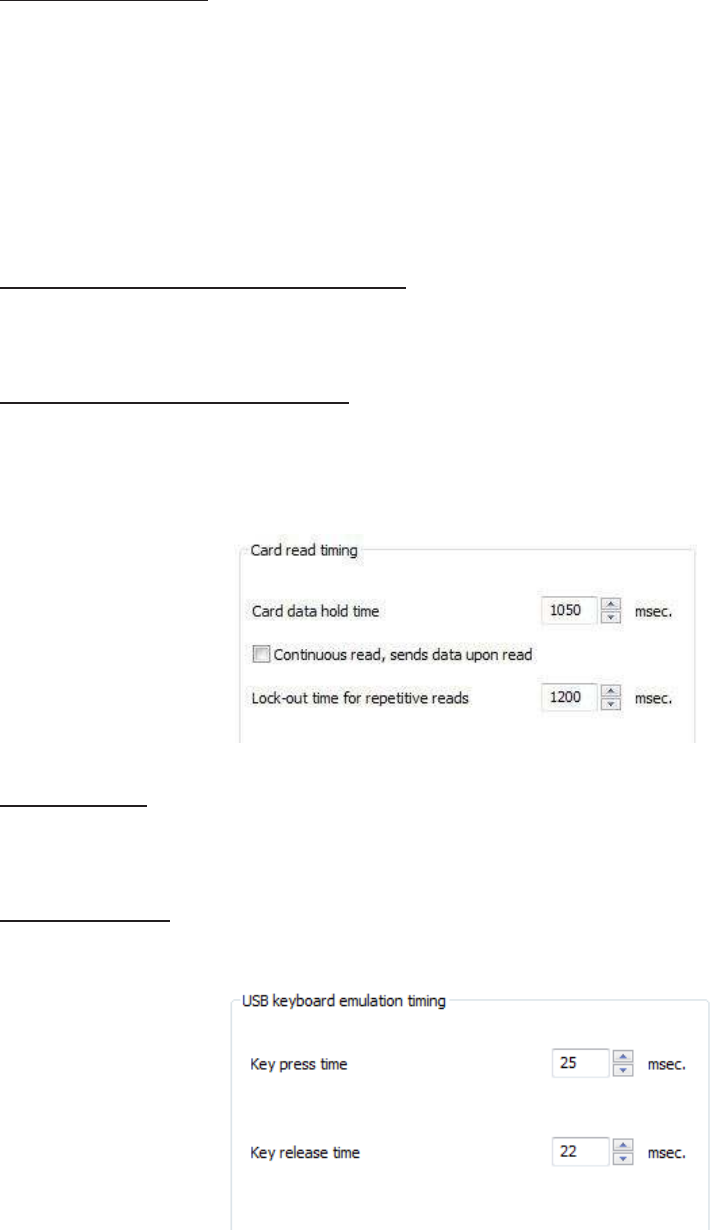
Timing Tab
Use
this tab to
configure
the
device’s card
timing
and USB keystroke
timing.
Card Data Hold Time: This option allows
for
users
to
determine
in
msec’s
how
long they need
t
o
wait
before
the
device
is
able
to
read
the
next card
in
line
(which is
also
how
long
the
LED
will
remain green
after a card
read).
The
timing
options can range
from 50 to 9950
min
/
max
(50msec increments
only)
and
the
default
is
set
to
1000
.
Note: This
is how
long
the
data
is
available
for the
SDK
user
.
Continuous
Read, Sends Data Upon Read:
When
a card
is
placed on a device,
this
option
will al-
low the
data
to
be sent c
ontinuously
.
Lock-Out Time
for
Repetitive Reads: The
time that it
takes
the
reader
to
read another
card.
Must
be equal
to or
greater than
the
hold
time
and
is
only done
in
50msec
increments.
Note:
For a
2
configuration device (pcProx
Plus
)
the
lock-out
time is the
same as card
data
hold
time.
Key Press Time: The length
of time the
key
is
held down. The minimum value
is
0
.
The
maximum
is 6
40
.
The default
is
20
.
Key Release Time: Enter
the time
delay between keystrokes.
If
set
to
0
,
the
reader
will output as
fast
as
it
can go. The minimum value
is
0
.
The maximum
is 6
40
.
The default
is
20
.
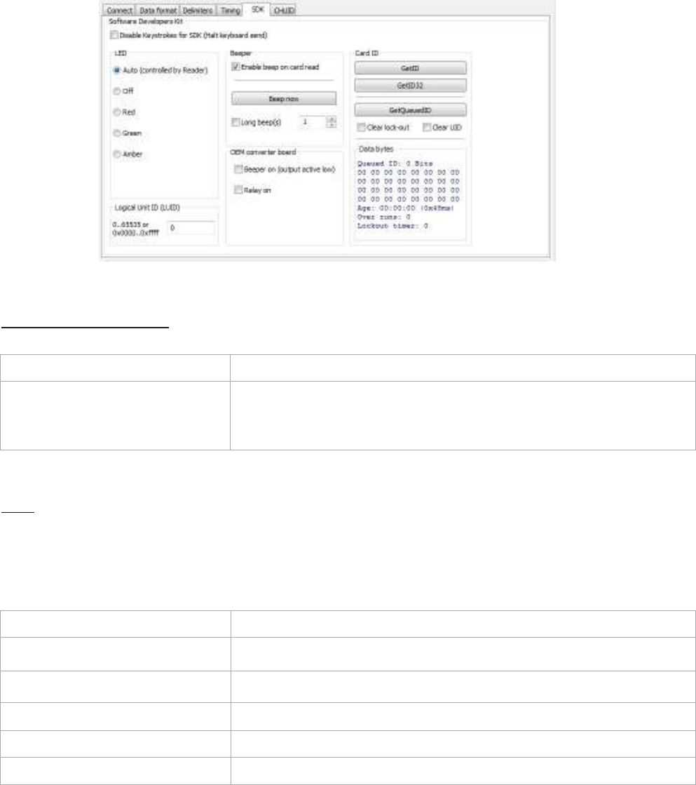
SDK
Tab
Use
this tab to
configure
the
Sof
t
w
ar
e
Developer’s
Kit
(
SDK)
functions, as
well
as enable and
disable
keystroking.
Sof
t
w
ar
e
Developers
Kit
Function Description
Disable
Keystrokes
for
SDK
(Halt
Keyboard
Send)
Check
to
disable keystroking.
When
keystroking
or unsolicited
serial
out is
disabled,
all
card data must be read via
the SDK
functions.
LED
The LED section allows users
to
control
the
LED
light
actions on
the
device
to
provide users
info
regarding
the
card
data.
Function Description
Auto
Select
this to
make
the
device set
the
LED
c
olor
.
Of
f
Select
this to
set
the
LED
to off
Red
Select
this to
set
the
LED color
to re
d
.
Green
Select
this to
set
the
LED color
to
gr
een
.
Amber
Select
this to
set
the
color
to
amber
.
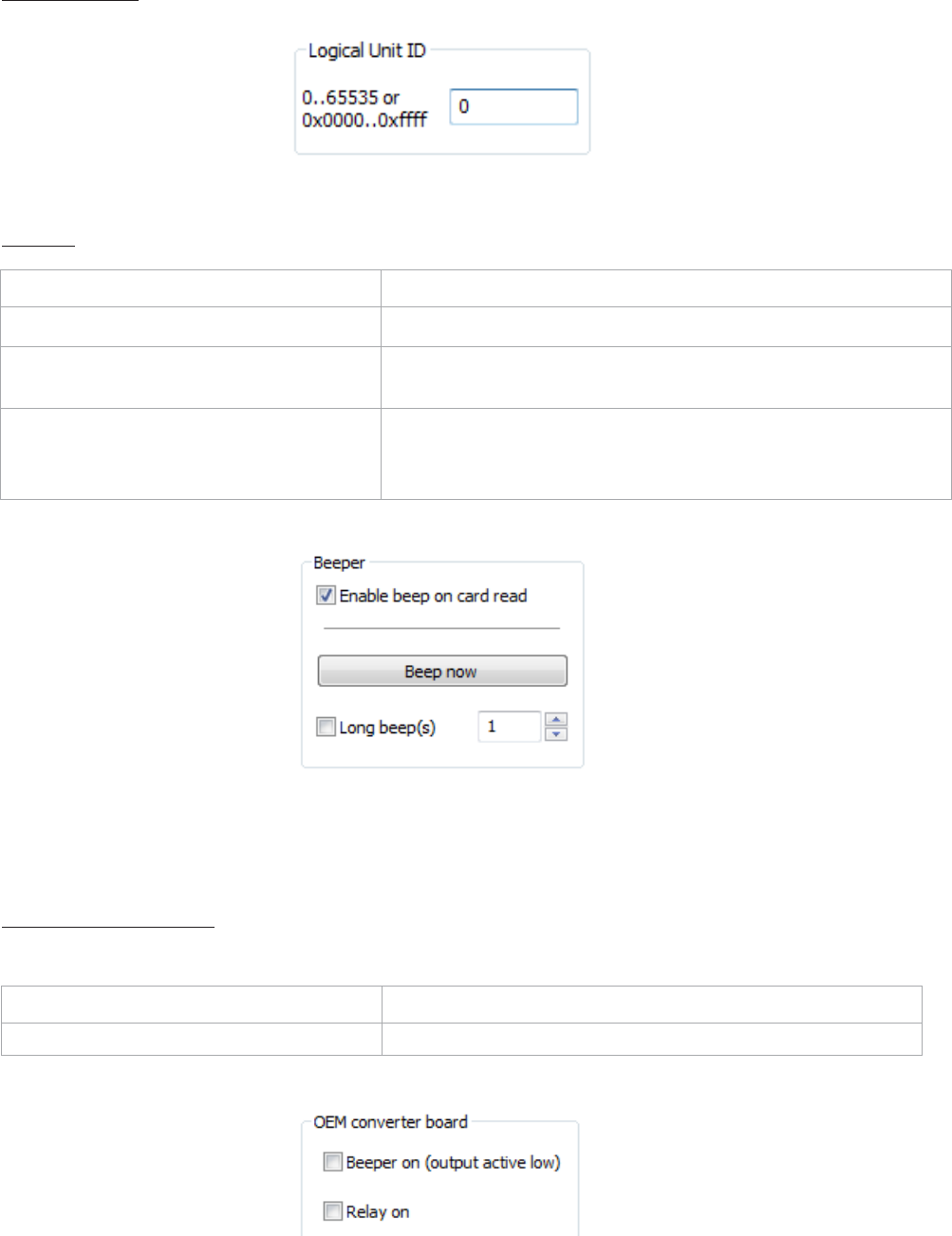
Logical
Unit
ID:
A
user defined 16
bit
Logic
Unit ID to identify
one device
from
another
.
Beeper
Function Description
Enable Beep on Card
Read
Check
this to
set
the
device
to
beep when a card
is read.
Beep
Now
Press
to
listen
to the
beep
the
reader
will
provide when
in
use.
Long
Beep(s)
Check
the
box
to
configure a long beep
of
375 msec.
B
y
default
the
beep
is
se
t
to
a short
beep
of
1
25
msec.
2
long
beeps
or 5
short
beeps are allowed
only
The number value
input
area
to the right of the
Long
Beep(
s
)
box
is
designated
for the
number
of
beeps
to
produce when
the
device
is in use.
OEM
C
onv
er
t
er
Board
Function Description
Beeper On
(Output Active Low)
Check
this to turn the
device beeper
on.
Relay
On
Check
this to
activate
the
OEM
board.
Card
ID
Function Description
GETID
Click while scanning a card over
the
device. The
ID
displays under
the
button. This returns
64 bits maximum.
GETID
(32)
Click while scanning a card over
the
device. The
ID
displays under
the
button. This returns 255
bits maximum.
GetQueuedID
Click
to
display
the
last card data read. This returns 255
bits maximum.
Clear
Lockout
Check
to
clear
the time
remaining
to
allow
the
device
to
read
the next
card
immediat
ely
.
Clear
UID If
clearUID
is
set,
the
card and
the
over
run
counters
will
be cleared
for
the
next
read.
If
clearHold
is
set,
the
reader
will
be ready
to
read another
card
immediat
ely
.
GETID Data
Display
The
Most
Significant Byte
is first
–
79
.
The Least Significant Byte
is
last –
A1.
GETID(32) Data
Display
GetQueuedID Data
Display
HH:MM:S
S
displays –
00:00:06
CHUID
Tab
This
tab
allows manipulation
of all
fields on
the
Federal Information Processing Standard
(FIPS
)
20
1,
or proximity
cards. Use
the
red buttons
to
configure additional fields. The fields can be moved
t
o
change
the
order displayed
in the
binary
bit
pattern
displa
y
.
Function Description
Define Fields
Click
to
select
the
number
of
source
bits to
define
the
fields.
The
correct type must
be selected
to
allow
for all
card
bits to
be
manipulat
ed.
Enable
Check
to
enable
the
highlighted field. This allows
the
delimiters
to be
output
and
the
corresponding card
field to
be processed and output.
All
green fields are enabled.
All
red fields are
disabled.
Keyboard
Click
to
select key delimiters
that
are stored
in the
device’s flash
memory
that
precede card data output. Each
field
may have
from 0
– 14
key
strokes.
C
lear
Click
to
clear keystrokes preceding
the
card
data.
Decimal
Click
to
display
the
card
field in
decimal
format.
Hex
Click
to
display
the
card
field
as a base 16 number
in
uppercase
HEX
0
–
9
and
A
–
F.
BCD w
/
P
arit
y
Displays
the
card data
in
binary coded decimal, where each
5 bits
represent
1, 2,
4, 8,
and
parit
y
.
FASCN data
is
always odd
parit
y
.
Function Description
Advanced
Click
to
display
the
binary
bit pattern.
GetID
Click
to
display
the
binary
bit
pattern captured
from the card.
Star
t
Bit
Enter a number
to
define
the left
most significant starting
bit for the
field.
Bits
Enter the number
of bits to
add
to
the
Star
t
Bit
to
define the range
of
bits
in the field.
Digits
This
is the
number
of
digits
that will
display
in
a selected
field.
Up
Click
to
move
the
highlighted
field
up one
position.
Down
Click
to
move
the
highlighted
field
down one
position.
Advanced
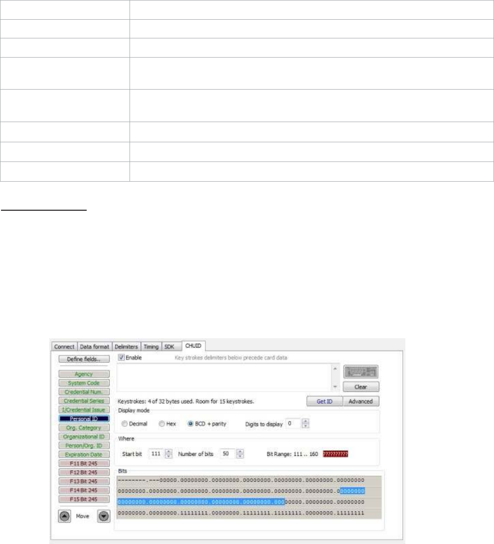
Button
This displays
the bit
ranges
of the card.
Click each
field button to
display
the
location
of the
card binary data.
In the
example below,
the
Personal
ID
starts
at bit
111,
is 50 bits
long, and
is
10 digits. The
Bit
Range
is
111
.. 160 and
the card
bit
pattern
is
highlighted. This
output format is
displayed
in
binary coded decimal
with parity (BCD
with
Parity). This
is the 245 bit
configuration.
If
any additional keystrokes were entered
to
precede
the
card data, click Clear
to
remove
them.
Note: The message
that
displays
the
number
of
bytes used and
how
much room
for
k
e
y
str
ok
es
above
the
Advanced
button is
determined
by the
device’s flash
memory
.
In this
example
the
configuration is: “Keystrokes:
8 of 32
bytes used. Room
for
14
keystrokes.”
Every
field is
15
keystrokes maximum.
All
fields share
96 bytes.
The
Bit
Range
that
displays
to the left of the
binary
bit
pattern
is the
Star
t
Bit field total + the
Bits
field total
– 1.
Get
ID
Click
GetID
and scan
the
card
to
display
the output format of the
FIPS
20
1
and
proximity
card and
the
interpretation display
of the
card data. Click
GetID to
define
the
fields
to
set up
the device.
In this
example, The Agency data starts
at bit
11,
is
16
bits
long, and
is 5
digits. The location
of the
agency data
is
highlighted
in the
binary
bit
pattern. The
Bit
Range
is 6
..
25.
The actual card data displays
in
blue below
the
binary
bit
pattern layout. The interpretation
of
the
car
d
data displays
in
red
in the text
field. The card data
in
blue
will
always be
the
same. The card
data
in
red changes based on configuration settings flashed
to the device.
Note: Click Clear
to
delete
the
red card data
in the text
field.
A
confirmation message
will
displa
y
.
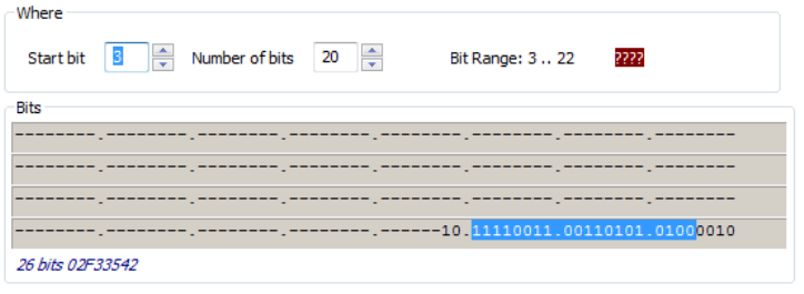
The Star
t
Bit
changes
the
actual location
of the
selected
field
on
the
binary
bit pattern.
Note: The ‘????’
that
display
to the right of the
Digits
field
indicate
the
BCD
parity is
incorrect.
Verify
the
correct
field is selected.

Change Fields
Configuration
Click on the
appropriate
field
button
and uncheck
Enable
to remove field data from being
displayed.
In the example
below,the
Agency,
Persona
liD,
and Expiration Date f
i
elds
have been
removed.
Additional function
keys display to configure more
fields.
l
r
D
e
f
i
n
e
F
i
e
l
d
s
/
[1]
E
n
a
b
l
e
K
e
y
s
t
r
o
k
es
b
e
l
o
w
pr
ec
e
d
e
c
a
rd
da
t
a
11
<
-
E
=
NT
E
=
-
------- ----- .
I
B
I
Credent
i
i
l
Num
.
]
K
e
ys.
[
Credent
i
a
l
Series
]
[
I!
Credent
i
i
l
Issu
e
]
I
Or
g
.
Category
]
IOrganizational ID I
K
ey
strok
e
s
:
7
o
f
50
b
yt
e
s
u
se
d
.
R
.
oo
m
f
o
r
14
k
e
y
st
r
o
k
e
s
.
[
P
erso
n/
Org
.
10
]
,---
:-:;c:c
FOS B
i
t
190
Dec
i
m
a
l
t)
HEX
@
BCD
W
I
Pa
r
ty
I
,..
Advanced
I
I
Bit
R
a
n
g
e
:
1
3
1.
.
5
0
e
7
EB
F09
Bi
t
23
5
FlO
Bi
t
23
5
F11B
i
t
24
5
F12
B
i
t
24
5
F13 B
i
t
24
5
F14
B
i
t
24
5
F1
5
B
i
t
24
5
0
A
u
t
o
f
oc
u
s
]I
Un
t
i
t
l
ed
-
N
ot
e
p
a
d
=
@J iooo!Joooj
l
1
F
il
e
E
d
;
,
_
F
o<
m
_
•
t
_
v
;
..,
H-e--l'p
----------------
71
5
00
2
9
1
1
1
7762
1
.
0/0,0000
Assign Preceding
Keystrokes
If
Enable
is
checked
for
a field, specific keystrokes can be assigned
to
precede card data
output.
Note: The Scan Code
output for the
key selected displays above
the list of keys.
Click Clear
to
remove
all
preceding keystrokes as
appropriate.

Each
single keystroke entered to precede card data equals1 byte of
memory.
Connect Data format Delmi
iters
Tming
SDK CHU
D
c_----------------------,
I
Define
field
s
.,
]
En
abl
e
Key
strokes
delimiters below
precede
card
data
System
Code
credential...,,
I
OedenbaiSeries
I
I/Qedenllal!ssue
I
Personal
ID
I
o-
g.
Category
I
Or
oarlzaOOnal
ID
I
Petson}Org.ID
I
:
#
E
xp
:
:
i
g
ra
:
t
:
ion
Date
Keystroke
s
:
4
o
f
26
b
y
tes
u
se
d
.
R
oom
for
14
key
s
troke
s
.
D
i
spla
y
mod
e
0
Dedm
a
l
0
Hex
@
BCD
+
pa
r
i
ty
Dig
i
ts
to
d
i
splay
0
Wh
e
r
e
Start
bi
t
-
-
Number
o
f
bits
·
I
Ad
v
anc
e
d
I
1
V
i
rt
u
a
l
K
ey
b
oar
d
·
s
e
l
e
ct
keycode an
d
mo
d
i
f
e
r
(
s
)
F13Bit245
Code:
0}1)004
Mo
ve
Output
test
a
r
ea
O
AutoG
eti
D
Read
y

If any special character is selected with a keystroke, this equals 2 bytes of
memory.
Conn
ec
t
Data
forma
t
De
limi
t
e
rs
r
ll'l'ling
SDK CHUID
c_----------------------,
I
Oe
fne
fiel
d
s..
-
-
'"
=
=
-
e
K_eY
'
_
t
_
roke
_
d
_
e
l
i
_
m
i
t
_
e
"
_
b
_
e
_w_
p
_
r
e
_
<
_
e
de
<a
_
rd
_
d
_
a
ta
_
SvstemCode
Credential
Nun.
<
SHIFT+a
>
[BliJ
Credential
series
Ke
y
s
b"oke
s
:
4
of
26
b
y
te
s
u
sed
.
Room
fur
1
4
keystrokes
.
IJCredential
Issue
Displ
a
y
mo
d
e
Personai.ID
[
Advanced
I
Org.
CateQOf"y
Oroar!zational
ID
Person
}Qr
g.
10
Decima
l
Hex
@
BCD
+
pa
r
i
ty
Dig
i
ts
to
d
i
spla
y
0
E:3
W
h
e
r
e
Numb
e
r
of bits
Bit
R
ang
e
:
6
..
2
5
ill
Expi"
·
·-
·
t
D
M
e
a
;
;
Star t
bit
F
ll
Bit
11
tu
a
l
K
eyb
o
ar
d
-
se:
l
e:
ct
k
ey
c
od
e:
a
n
d
m
od
i
f
i
e
r
(s)
F12Bit
2
4
S
F13Bit245
Fl4Bit
2
4
S
Fl
5Bit245
liJ
Mo
ve
OJ!pu
t
t
es
t
a
r
ea
[J
Au
to
GetiD
Re
a
dy
[]
Keepshifu
If all the
keystrokes have been assigned
to the
fields,
the
following message
displa
y
s:
Depending on
the
active document
/
windo
w
,
additional functionality can be assigned
to
a field.
F
or
example,
if the
card data
is
read
in
OpenOffice,
the
Note feature can also be
assigned.
Select
the
appropriate field. Click
the
keyboard icon. Check
L
ef
t
C
ontr
ol
.
Check
L
ef
t
Alt.
Click
n
.
Click Inser
t
.
Click Flash
to write this
configuration
to
flash
memory
.
Verify the
active window
is
OpenOffice. Scan
the
card. The Notes function opens when
the
card
is read.
The value assigned
to the
function key
in the
active document
/
windo
w
determines
the output.
Note: This configuration
utility
creates a ComSpecPort.txt
file
and saves
to the
default
dir
ectory
.
This
file
can be opened and deleted
at will.
FIPS
20
1
Card
Configuration
In
order
to
configure a
FIPS
20
1
card:
•
Click Advanced
to
display
the
card data
in the
binary
bit
pattern
to
determine
bit
length
and
format
•
Click
GetID
and present
the
card
to the reader
•
Define
the
fields
to
match
the
specific
output
•
Configure any additional fields as
appropriate
•
Flash
the
configuration
to memory
The Advanced
button displays:
•
Star
t
bit location
•
Number
of bits for
a specific
field
•
Number
of
digits
for the field
•
Location
of the field within the 245 bit range

ASCII Command Protocol
4
ASCII
Overview
ASCII Command Protocol
(ACP) allows
the
user
to talk
directly
to the
device
without
a DLL
or special
application. The serial Prox communicates using ASCII commands. Printable ASCII commands
at
9600
baud, no
parity
1
stop
bit,
and no echo, can be sent
to the device.
Note: USB devices
that
are
virtual COM port
do
not
need
the
baud rate set. The
input is
buffered
by
the
device and executed when a carriage
return
(
CR)
or
line feed line feed (LF)
is
t
yped.
The
unit
then parses
the
command and performs
the
operation, and displays
the
results
or error
code.
“\r\nRF
IDeas>” where
\r
represents a CR and
\n
represents a
LF
that
displays on
the
command
line.
All
commands begin
with the
prefix
rfid:
and end
with
a Return key, CR
or
LF
.
Determine the
COM
P
or
t
Windows
Use device manager
to
display
the COM
ports. Open
the
serial
COM
port.
If it is
a CDC
virtual port,
open
the
newly installed device
that
was
created.
Linux
Most
Linux distributions include Minicom. Download
putty
(
www
.putt
y
.
or
g
) to
communicate
with
the
serial device
if Minicom is not available.
After the
USB CDC device
is
enumerated on
the
Linux machine a device
of
either
/
de
v
/
tt
yACM0 or
/
de
v
/
tt
yA
CM1
is
found
in the
/
de
v
/
dir
ectory
.
Minicom
users may have
to
create a symbolic
link from
/
de
v
/
tt
yACM0 to
/
de
v
/
modem
using
the
command
ln -s
/
de
v
//
tt
y
/
A
CMO
/
de
v
/
modem
or
ln -s
/
de
v
/
tt
yA
CM1
/
de
v
/
modem.
Mac
OS
X
The
/
de
v
/
cu.usbmodemf
a211
device
is
found on a
Mac
OS
X
. Use
putty to
communicate
with this
device.
Connect Serial Communications
P
r
ogram
Open
putt
y
.
e
x
e
.
Click Connection
a
Serial
and set
the
Speed
(baud) to
9600
,
Data bits to 8, Stop
bits to
1, and
Parity to
None. Flow
control is not
needed as there
is
no software
or hardware
handshaking.
Click
Ses
sion
.
Note: Use Hyper Terminal instead
of putty with the
XP operating
system.
Highlight
the
appropriate session. Click Save. Click
Apply
.
P
utt
y
opens. Type
rfid:help
and press
Ent
er
.
The Help command
output
displays. The complete
list
of
Help command
output is
found
in this
section
of the
Configuration User
Manual.
Command
Structure
Commands are
not
case sensitive. Characters assigned
to
variables are case
sensitive.
·
All
commands begin
with
a prefix string followed
by
one
or
more
t
oken
strings
with
a
period
delimiter character between multiple
tokens.
·
Functions must end
with
a CR
or
LF
.
·
Variables can be assigned a value
with
an equal sign followed
by the
value
or
queried
with a
question
mark.
·
Any
control characters other than
CR, LF,
and backspace
terminate
the command.
·
The Escape key cancels a
c
ommand.
The general syntax
is:
PREFIX TOKEN
{
DELIMITER TOKEN
} { {
=Value} | {?}
}
The prefix string
is rfid:

Command structure falls
into
one
of
three
groups:
1.
Perform a
function.
2. Assign a
variable.
3. Query a
variable.
P
er
f
orm
a
Function
A
function performs an operation
that
may
or
may
not
display any results.
A
function may
not be
queried.
An
example
of
a function
is to write the
variable settings
to
flash memory
using
rfid:cfg.write
CR
.
Certain functions
that
display a value
or
series
of
values display
the
string between curly braces
for
easy parsing. For example,
the rfid:qid
function
output displays:
{0x00BB,
1,
0x0000
,80;0x00000080
1CD19
31B2F14}
Assign
a
Variable
There are three
t
ypes
of variables:
1.
Boolean
2.
Integer
3.
Character
Examples
of
Boolean
As
signments
rfid:op.beep=0
rfid:op.beep=true
rfid:op.beep=False
rfid:op.beep=F
Examples
o f
Integer
As
signment
rfid:out.led=0003
rfid:out.led=3
Note: Some integer values require a 16
bit
hexadecimal
entry
.
For Example: pcProx Plus card
t
ypes:
rfid:cfg.card.type=0xFFFF
Examples
of
Character
As
signment
rfid:Delim.
Chr
.
f
ac=’:’
CR
rfid:Delim.
Chr
.
f
ac=’x3a’
CR
Query a
Variable
Query a single variable
to
display
its
current
value.
·
Booleans display as
true or false.
·
Integers display as
0
..
255
with
leading zero
suppression.
·
Characters display as single quoted printable ASCII characters
in the
range
0x20
..
0x7E.
·
Values
from 0x00
.. 0x1F and 0x7F..0xFF
will
be
with
a leading backslash lowercase
x
and
the
two digit
upper case hex
number
.
· The
output of the
variable displays between curly
braces.
For example: RF
IDeas>r
fid:out.led?
{3}
Variables are set and stored
in
RAM and are
lost
when
the utility is
closed. Use
the cfg.write function
to write the
RAM configuration
to
flash
memory
.
Use
the
cfg.read function
to
read
the
flash
memory
.

Help
Command
Help displays
the
commands followed
by its
data type
and expected syntax. The table below
displays
the
Help command output. The functions display
in blue.
rfid:beep.now
rfid:disp
.
f
ac.he
x
‡ rfid:cfg
rfid:disp
.
f
ac.send
‡
rfid:cfg.card.hipri
rfid:disp
.
f
ac.strip
‡ rfid:cfg.card.list
(Function) rfid:disp.hex.lower
‡
rfid:cfg.card.type rfid:disp.id.digits
rfid:cfg.read
(Funtion) rfid:disp.id.hex
rfid:cfg.reset
(Function)
rfid:help
(Funtion)
rfid:cfg.write
(Function) rfid:op.beep
rfid:chr
.
1
rfid:op
.
c
ont
rfid:chr
.
2
rfid:op.sdk
rfid:chr
.
3
rfid:out.led
rfid:chr.count.lead
rfid:qid
(Function)
rfid:chr
.
c
ount.
tr
ail
rfid:qid.hold
rfid:chr
.
eol
rfid:qid.id
rfid:chr
.
f
ac
rfid:qid.id.hold
rfid:chr
.g
one.
1
rfid:time.hold
rfid:chr.gone.2
rfid:var
(Function)
rfid:cmd.echo rfid:wieg.id.bits
rfid:cmd.prompt rfid:wieg.inv.bits
rfid:dev.luid rfid:wieg.qual
rfid:de
v
.par
t
(Function) rfid:wieg.qual.bits
rfid:dev.ver
(Function) rfid:wieg.rev.bits
rfid:disp
.
6
4bit
rfid:wieg.r
e
v
.b
yt
es
rfid:disp
.
f
ac.
6
4bit
rfid:wieg.strip
.lead.bits
rfid:disp
.
f
ac.digits
rfid:wieg.strip
.
tr
ail.bits
‡ Applies only
to the
pcProx
Plus
Help Command
Summary
C
ommand
Data
Type
R,
W,
R/W
Definition
rfid:beep.now INT
W
Sounds
the
beeper immediately up
to 5 short
beeps
or 2
long
beeps.
beep.now
variables:
1
– single
short
beep
2
–
two
short
beeps
3
–
three short
beeps
4
–
four
short
beeps
5
–
five short
beeps
10
1
– single long
beep
102 –
two
long
beeps

C
ommand
Data Type
R,
W,
R/W
Definition
r
fid:cf
g
(‡
pcProx Plus
only)
INT
R/W
The pcProx Plus reader has
multiple
configurations.
Each
configuration has
the
settings associated
with
a card
t
ype.
When a
configuration
is
changed,
all
other
related
settings reflect
that
configuration number
.
Ex
ample:
To set configuration #1
to
keystroke
out the card
ID
preceded
by #1/ the
following
commands
would be
entered:
rfid:cfg=1
fid:char
.
c
ount.lead=3
rfid:char
.
c
ount.lead=0
rfid:char
.
1=’#’
rfid:char
.
2=’1’
rfid:char
.
3=’/’
To then set configuration
#2 to
precede
it’s card
ID with #2/ the
following commands would
be
entered:
rfid:cfg=2
fid:char
.
c
ount.lead=3
rfid:char
.
c
ount.lead=0
rfid:char
.
1=’#’
rfid:char
.
2=’2’
rfid:char
.
3=’/’
r
fid:cf
g.
car
d.hipri
(‡
pcProx Plus
only)
BOOL
R/W
Enable
priority
card read. IF True,
current
configuration
is
given
priority
over
the alternate
configuration
r
fid:cf
g.
car
d.lis
t
(‡
pcProx Plus
only)
F
unction
View list of
suppor
t
ed
card
t
ypes
and
their
hexadecimal entries
for the
rfid.
cf
g.
car
d.
t
ype
command.
r
fid:cf
g.
card.
t
ype
(‡
pcProx Plus
only)
INT
(hex)
R/W
Verify or
Set Card
type
for
current
configuration
in
RAM as 16
bit
INT
(0x0000
..
0xFFFF)
Note:
0x0000 is off
r
fid:cf
g.r
ead
F
unction
Read
the
flash memory settings
in to RAM.
r
fid:cf
g.r
eset
F
unction
Reset
the
flash memory
to the
factory
defaults.
r
fid:cf
g.
writ
e
F
unction
Write the
variables
from
RAM
in to flash
memory
.
r
fid:chr
.
1
CHAR
R/W
1st
card data delimiter
character
(A -
Z,
0 -
9, a
- z or
ASCII
\0x00
….\0x0D)
u
r
fid:chr
.
2
CHAR
R/W
2nd card data delimiter
character
(A -
Z,
0 -
9, a
- z or
ASCII
\0x00
….\0x0D)
u
r
fid:chr
.
3
CHAR
R/W
3rd
card data delimiter
character
(A -
Z,
0 -
9, a
- z or
ASCII
\0x00
….\0x0D)
u
rfid:chr.count.lead INT
R/W
Verify or
Set
the
leading character
count
(0 to 3)
u

C
ommand
Data Type
R,
W,
R/W
Definition
r
fid:chr
.
c
ount.
tr
ail
INT
R/W
Verify or
Set
the
trailing character
count
(0 to 3)
u
r
fid:chr
.
eol
CHAR
R/W
Verify or
set end
of
line termination
character
( A -
Z,
0 -
9, a
- z or
ASCII
\0x00
….\0x0D)
r
fid:chr
.
f
ac
CHAR
R/W
Verify or set
separating character between
the facil-
ity
code and
ID data( A -
Z,
0 -
9, a
- z or
ASCII
\0x00
….\0x0D)
Ex: 123 ;
456
7
89
r
fid:chr
.g
one.
1
CHAR
R/W
1st character sent when card
is removed
( A -
Z,
0 -
9, a
- z or
ASCII
\0x00
….\0x0D)
rfid:chr.gone.2 CHAR
R/W
2nd character sent when card
is removed
( A -
Z,
0 -
9, a
- z or
ASCII
\0x00
….\0x0D)
rfid:cmd.echo BOOL
R/W
IF True, enable echo
of
user
input
and use
of
backspac
e
key
r
fid:cmd.prompt BOOL
R/W
IF True, enable RF
IDeas command
prompt
r
fid:dev.luid
INT
(hex)
R/W
Verify or
set
the
logical unique identifier
as 16
bit INT
(0x0000
..
0xFFFF)
r
fid:dev
.par
t
F
unction
Read
the
device
part number
r
fid:dev
.
v
er
F
unction
Read
firmware version
(major
. minor .
variant)
r
fid:disp
.
6
4bit
BOOL
R/W
IF True, use
64 bit
math on
ID data
r
fid:disp
.
f
ac.
6
4bit
BOOL
R/W
IF True, use
64 bit
math on
facility
code
data
rfid:disp.fac.digits INT
R/W
Verify or
set Length
of facility
code
output
(up to 25 digits)
rfid:disp.fac.hex BOOL
R/W
IF True, enable
facility
code
output
as
hex
rfid:disp.fac.send BOOL
R/W
Enable
output of facility code
r
fid:disp
.
f
ac.s
trip
BOOL
R/W
Set
to
True
to
separate
ID
and FAC. False processes
ID
and FAC
t
og
ether
.
rfid:disp.hex.lower
BOOL
R/W
IF True, hex
ID
data
is output in lowercase
r
fid:disp.id.digits BOOL
R/W
Verify or
Set
ID
data length
(0 to 25 digits)
Note:
If
value
is
shorter than actual
Id
length
the left most
significant digits
will
be
truncated
rfid:disp.id.hex BOOL
R/W
IF True, enable
ID
data
output
as
hex
r
fid:help
F
unction
View
menu
of
commands, summary
of output types
and variable
options
rfid:op.beep BOOL
R/W
Beeper
output
control True=beep,
F
alse=silent
r
fid:op
.
c
ont BOOL
R/W
Continuous read mode
True=continuous
output, False=single
output of
credential
data
rfid:op.sdk BOOL
R/W
IF True, enable Quiet mode. (IE: Credential data
is not
displayed) Note:
data can
still
be retrieved
using
function
rfid:qid.
r
fid:out.led INT
R/W
LED
output control
0=off
,
1=red,
2=
gr
een
,
3=Amber
(Immediate
out w\o
writ
e)
255=Automatic control
by
reader (requires
write
t
o
flash) red on standby, green when credential
is read

C
ommand
Data Type
R,
W,
R/W
Definition
r
fid:qid
F
unction
Reads current queued
ID data
EXAMPLE
Output String:
{0x1000
,
2,
0x0000
,80;0x00000080
1DD1910
B2F04}
---Note the
use
of
commas and
semicolons--
FORMAT
of Output String:
{
AG
E
,
O
VERR
UN
,
L
OCK
OUT
,
BITC
OUNT
;
ID
}
AGE (New: Age
(in
hex)
of
last card read as
a
multiple
of
48ms. Value stops
at
0xFFFF.
Use
qid.id function
to
clear
the
age counter.
As
shown:
the
card was read
4,096 (0x1000 hex)
x
.
048
=
196.608 seconds ago
or 3
minutes
and
16
seconds.
OVERRUN counter (Values:
0
through
255):
number
of
times buffer has been over
writt
en
with
new data
without
content
tr
ansfer
.
LOCKOUT: Time
(in
multiples
of 48ms) re-
maining
until
another card can be
read.
BIT COUNT
bit
length
of
card data
(26 to 255).
As
shown: The
ID
contains
80 bits.
ID: Card data
in
hexadecimal.
As
shown: Card
is
80 bits
and
is 0x000000801DD1910B2F04.
r
fid:qid.hold
F
unction
Read
the
card data and reset lockout
timer
.
Once
the
function
is
called, a new card can
be
read immediately after
without
waiting
for the
lock
out time
period
to expire.
r
fid:qid.id
F
unction
Reads
the
card data, clears
the
age, overrun,
and
bit
count after function
is called.
r
fid:qid.id.hold
F
unction
Combined functions
of
rfid:qid.hold
and
rfid:qid.id
r
fid:time.hold INT
R/W
Verify or
set current data hold
time
setting
in
multiples
of
48ms.
(0 - 200)
Also
controls
duration
of
Green LED during
Auto mode.
r
fid:v
ar
F
unction
Outputs current command variables
in ram
(
Similar
to
a .HWG
file.) Output
can be
cap-
tured, edited and
written
back
into the device.
Note:
To prevent an
input
buffer
ov
erflo
w
,
delay
each character
by
several
milliseconds.
r
fid:wieg.id.bits INT
R/W
Verify or
set card data
output bit
count
(0- 255)
r
fid:wieg.inv.bits BOOL
R/W
IF True,
Invert
card data
output bits
(1
to
0
,
0 to 1)
rfid:wieg.qual BOOL
R/W
IF True, use wiegand qualifier
to verify
card
bit
count

r
fid:wieg.qual.bits INT
R/W
Wiegand Qualifier: Number
of bits (0 - 255)
card data must have
to
be acknowledged as
a
read
r
fid:wieg.r
e
v.bits BOOL
R/W
IF True, reverse
bits of
credential
output
lsb
t
o
msb
rfid:wieg.rev.bytes BOOL
R/W
IF True, reverse
the
bytes
of
credential
output
LSB
to MSB
r
fid:wieg.s
trip
.lead.bits
INT
R/W
Leading
parity bit
count
to
be stripped
from
credential data (options:
0 =
none,
1
to
142
bits
)
r
fid:wieg.s
trip
.
tr
ail.bits INT
R/W
Trailing
parity bit
count
to
be stripped
from
credential data (options:
0 =
none,
1
to
142
bits
)
Key:
R
=
read only
command
W = Write
only
command
R/W =
Command can be read
for its
current value
or written with
a new
value.
Note: Value changes are stored
in
RAM
till
rfid:cfg.write
is
used
to
store
the
value
in to
F
lash.
u
T
hese
three commands identify
the
delimiter characters
that
can display. Three characters may be divided up as
pr
e
and
/
or
post delimiters. The rfid:count.lead command identifies how many
of the
three characters
(
chr
.
1
..
chr
.
3)
displa
y
before
the
card data. For example,
if
rfid:count.lead
is
set
to
1,
only one character displays before
the
card
data
and
chr.2 and chr.3 can be set as post delimiters. Then rfid:count.trail can have a value
of
0
,
1,
or
2.
If rfid:count.lead
is
2,
chr
.
1
and chr.2 are set as leading delimiters. Then, only chr.3 can be set as a trailing
delimit
er
.
However they
are
used,
the
same character location cannot be used
for both
leading and trailing
delimit
er
.
Variable
Command
The var command displays
all
variables. The command
output
can be captured and played back
into
the
device. There must be a delay
of
several
milliseconds after
each character
or the
pcProx
serial
input
buffer
overflows.
rfid:beep.now
rfid:disp
.
f
ac.he
x=False
rfid:cfg=1
rfid:disp
.
f
ac.send=False
rfid:cfg.card.hipri=True
rfid:disp
.
f
ac.strip=T
rue
rfid:cfg.card.type=0xEF04 rfid:disp.hex.lower=
rfid:chr
.
1
rfid:disp.id.digits=0
rfid:chr
.
2
rfid:disp.id.hex=False
rfid:chr
.
3
rfid:op.beep=True
rfid:chr
.
c
ount.lead=0
rfid:op
.
c
ont=F
alse
rfid:chr
.
c
ount.
tr
ail=0
rfid:op.sdk=False
rfid:chr
.
eol=’\x0D’
rfid:out.led=255
rfid:chr
.
fac=’\x00’
rfid:time.hold=20
rfid:chr.gone.1=’\x00’ rfid:wieg.id.bits=16
rfid:chr.gone.2=’\x00’ rfid:wieg.inv.bits=True
rfid:cmd.echo=True rfid:wieg.qual=False
rfid:cmd.prompt=True rfid:wieg.qual.bits=26
rfid:dev.luid=0x0000 rfid:wieg.rev.bits=False
rfid:disp
.
6
4bit=F
alse
rfid:wieg.r
e
v
.b
yt
es=F
alse
rfid:disp
.
f
ac.
6
4bit=F
alse
rfid:wieg.strip
.lead.bits=1
rfid:disp
.
f
ac.digits=0
rfid:wieg.strip
.
tr
ail.bits=1
These five variables
work together
to
display leading and trailing
(pre
and
post)
card data
delimiters.
1.
rfid:chr
.
1=’\x00’
2.
rfid:chr
.
2=’\x00’
3.
rfid:chr
.
3=’\x00’
4.
rfid:chr
.
c
ount.lead=0
5.
rfid:chr
.
c
ount.
tr
ail=0
The
first
three commands identify
the
pre delimiter characters
that
can display. Three characters
may
be divided up as pre and
/
or
post delimiters. Count.lead identifies
how
many
of the
three
characters
(
chr
.
1
..
chr
.
3)
display before
the
card data. For example,
if
count.lead
is
set
to
1,
only one
character
displays before
the
card data and chr.2 and chr.3 can be set as post delimiters. Then count.trail
can
have a value
of
0
,
1,
or
2.
If
count.lead
is
2,
chr
.
1
and chr.2 are set as leading delimiters. Then
only
chr.3 can be set as a trailing
delimit
er
.
The same character can
not
be used
for both
a leading
and
trailing
delimit
er
.
r
fid:cfg=1
The pcProx Plus reader has multiple configurations.
Each has
the
settings associated
with
a card
type.
When the
configuration
is
changed,
all
other related settings reflect
that
configuration number
.
Example: To set configuration #1
to
keystroke
out
card
ID
preceded
by #1/ the
following would be
entered.
rfid:cfg=1
fid:char
.
count.lead=3
rfid:char
.
c
ount.lead=0
rfid:char
.
1=’#’
rfid:char
.
2=’1’
rfid:char
.
3=’/’
And now
set configuration
#2 to
precede
it’s
card
ID with
#2/
rfid:cfg=2
fid:char
.
count.lead=3
rfid:char
.
c
ount.lead=0
rfid:char
.
1=’#’
rfid:char
.
2=’2’
rfid:char
.
3=’/’
r
fid:chr
.
eol=’\x0D’
This command sends
the
End
Of
Line (EOL
)
character
at the
end
of the
card data. Typically
a
carriage
return
(
CR)
(0x0D) is used.
r
fid:chr
.
f
ac=’:’
This command sets a delimiter between
the
FAC and card
data.
rfid:chr.gone.1=’\x0A’
and
rfid:chr.gone.2=’@’
These commands
prompt the
device
to
send
the
characters
‘x0A’
and ‘@’ when
the ID
card
is
removed
if
they are
not ‘00’.
rfid:cmd.echo=True
This command echoes user
input
when
true
and controls
if
backspace sends a space,
backspace,
space
to
erase
the
last character
t
yped.
If
false,
it is
turned
off for
computer control. This value
can
be
written to
flash memory using cfg.write.
It
defaults
to true
on
cfg.reset.
r
fid:cmd.prompt=T
rue
This command displays
the prompt
when true.
If
false,
the prompt
does
not
display. This value can
be
written to
flash memory using cfg.write.
It
defaults
to true
on
cfg.reset.
r
fid:de
v
.luid=0x1234
This command sets
the
logical
unit
ID.
A
user-defined
2
byte value
to
identify
this unit.
r
fid:disp
.
64bit=F
alse
This command uses
64 bit
math
to
computer
64 bit
decimal digits. This should always be kept on.
If
true,
it
uses
64 bit math.
r
fid:disp
.
f
ac.digits=3
This command truncates
or
sets
the
FAC display leading
z
er
o
.
r
fid:disp
.
f
ac.he
x=F
alse
This command sends
the
FAC code
in
hex when true.
If
false,
the
FAC code
is
sent
in decimal.
r
fid:disp
.
f
ac.send=F
alse
This command sends
the
FAC code
if
true.
If
false,
the
FAC code does
not
displa
y
.
r
fid:disp
.
f
ac.s
trip=F
alse
This command separates
the
FAC
from the
card data when
true
so
it
can be independently
formatted
for
display.
If
false,
the
FAC code
is not
separated
from the
card
data.
r
fid:disp
.id.digits=16
This command sets
the
digits so
the left
most significant digits
will
be truncated. For example,
if the
card data
is
1234 and id.digits=3, then only
234
displays.
If the
card data
= 8
formats
the display
width by
truncating digits
or
adding leading
zeros.
rfid:disp.id.hex=False
Displays
the
card data as hexadecimal when true.
If
false, card data displays as a
decimal.
rfid:op.beep=True
This command sets
the
device
to
beep on a successful card read when true.
If
false,
the
device
will
not
beep even
if the
card
is
successfully
read.
rfid:op.cont=False
This command sets
the
device
to
continuously read when true.
It tells the
device
to
read
the same
card data over and over while
the
card
is
on
the
device.
If
false,
the
device only sends card data
once.
rfid:op.sdk=False
This command stops
the
device
from
displaying
the
card data when true, so
the qid or
SDK API
call
must be used
to
get
the
card data.
When true the
device
will
send
the
data via keystrokes
or serial
depending on device
t
ype
/
model.
rfid:out.beep=False
This command makes
the
device beep when true.
If
false,
the
device
will not
beep. This
is only
available
on OEM converter
boards.

r
fid:out.led=255
This command sets
the
variable and also sets
the output
LED color
in
RAM. Use
cf
.
writ
e
to write this
change
to
flash memory
to
persist across power
cycles.
LED
Value Description
0
OFF
1
RED
2
GREEN
3
AMBER
4..254
R
eserved
255
Controlled
by the device
rfid.out.relay= True
This command sets
the output
driver
to ON
(active
low)
when true. This
is
only available on
OEM
converter
boards.
r
fid:time.hold=20
This command sets
how
long
in 48ms
ticks
the
data
is
held
for the
active ID. This also controls
how
long
the
device keeps
the
LED green
in 48
msec ticks. The default
time is 20 *
0
.
048
=
0
.
960
seconds.
Note: The
qid.hold
resets
the
internal
timer this
value
initializes.
r
fid:time.lo=2
4
This command sets
how
long
in 48ms
ticks
the
card device has
to wait for
no card
in the
RF
field
t
o
begin accepting new card data. This prevents
the
same card data
from
being read over and over.
If
op
.
c
ont
is true this
value has no effect. The default
time is 24 *
0
.
048
=
1.15
seconds.
Note: The
qid.hold
resets
the
internal
timer this
value initializes, so
that
a new card can be
read
assoon as
the
data
is
transferred
to the
host
c
omput
er
.
r
fid:wieg.id.bits=80
This command sets byte reversal and also defines
the
FAC
bit size.
r
fid:wieg.inv.bits=
T
rue
This command sets
all
ones
to
become zero
in the
Wiegand data.
If
false,
all
zeros are set
to become
a
one.
rfid:wieg.qual=False
This command sets card reading
filter to off
.
If
true, card reading
filter is
on. This
is
related
to the next
command,
.qual.bits=80
.
r
fid:wieg.qual.bits=80
This command sets
the
device
to
read only cards
with this
many bits.
All
other size cards are
filtered
out.

r
fid:wieg.r
e
v
.bits=F
alse
This command does
not
reverse
all
bits.
If
true,
the
least significant
bits
are swapped
with the most
significant
bits.
rfid:wieg.rev.bytes=False
This command does
not
reverse
all the
bytes
in the
id.bits size field.
If
true,
all
bytes are
reversed.
r
fid:wieg.s
trip
.lead.bits=1
This command strips
0
.. 15
bits from the
most significant
bits.
r
fid:wieg.s
trip
.
tr
ail.bits=1
This command strips
0
.. 15
bits from the
least significant
bits.
ACP Error
Codes
ACP
Errors Descriptions
Error#1
Illegal Command.
Will return “Try
“rfid:help”. Possible
Wrong or
missing
prefix
“rfid:”
Error#2
Input buffer overrun. Too many characters received
without
CR
or
LF
Error#3
Illegal Operation.
-
Variable assigned
to
function
or
variable used as
function
Error#4
Range Error. Value assigned
to
variable exceeds
limit
(EX: 257
for
255
limit)
Tips and
Troubleshooting
5
Troubleshooting
If the
device
is not
working
or the
following error message
displays:
1. Check
to
be sure
the
device
is
plugged
into the
USB
or
RS-232 port.
When the
workstation
is
on and no card
is
being read,
the
LED
is
red.
A
valid
proximity
card causes
the
LED
to turn
green, provided
the
configuration
is not
set
to
only read certain
bit lengths.
2.
Only one
COM port
application can
own the
RS-232
port at
a time. Make sure there
is not
another
COM port
application running. This prevents
our
software
from
seeing
the device.
3. Verify the
correct model and
the
software configuration
screen agrees
with the device
attached.
4. Verify the port
agrees
with the
workstation
c
onnect
or
.
5. If the
device
still
does
not
work, unplug
it,
remove ‘General USB Device’ using
Windows
‘Control
Panel’
a
‘Add/Remove’
Hardware. Then reboot
the
workstation.
When the
workstation boots up, re-attach
the
device USB and
the
OS should re-install
the Windows
driver
automatically
.
Change
the
release
time to 1000
on
the
Timing
tab for
USB keystrokes
to
slow down
the
de
vic
e.
Open Notepad
or Word
and swipe a card
to
display
the
card data
to
see
the
actions
of any
non-printable
symbols.
If the
device does
not
read
the
card, contact
the
card
manuf
actur
er
/
vendor
to
verify
that the card
type
is
compatible
with the
device
model.
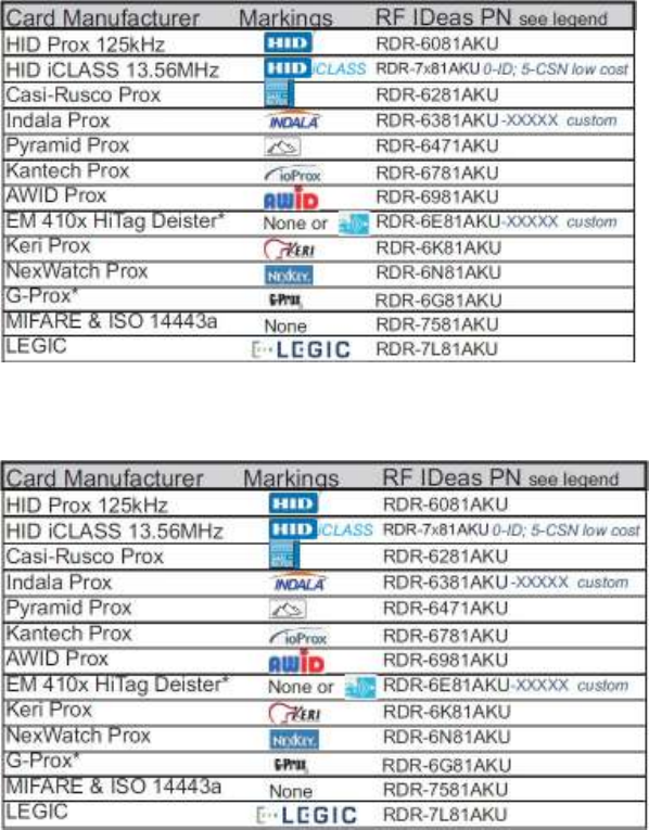
Frequently Asked
Questions
What
t
ypes
of credentials will your
desk
t
op
and OEM
products work
with?
Our products work
with virtually all
125 kHz
proximity
and 13.56
MHz
contactless cards
in the
industry
t
oda
y
.
The charts below can assist you
in
determining
what
RF
IDeas products
will
work
with
your particular credential. You can reference
the
RDR
part
number on
our
website
t
o
get
the
name
of the
particular product
or
you can simply email us
at
sales@RFIDeas.com
with
the
number and
we will
contact
you.
Solutions
for Identification:
Solutions
for Integrators:
When
I present my
card
t
o
the
pcProx
Enrollment
reader
the
number displayed
is not the
number
printed
on
my
card
or the
same number
my
access
control
s
y
s
t
em
displays, why?
Check
with
your supplier
for the
card
format
information, since there are some credentials
that
require a custom
format
reader. You may possess one
of
these
t
ypes
of
credentials. The
pcProx
Enrollment readers may need
to
be configured
to output the
required credential number
,
i.e. FAC,
ID or
CSN using
the
pcProx Enroll Configuration
Utility for
USB and RS-232 readers.
You can
download
our
configuration program free
of
charge
by cutting
and pasting
this
path
into you web
browser
http:
//
www
.rfideas.c
om/Sof
t
w
ar
e
/
pcP
r
o
xConfig.
e
x
e
.
Once downloaded please review
the
User’s Manual
for
configuration instructions.
If
you have any questions please contact
RF
IDeas
t
echnical
support.
What sof
t
war
e
application
can
I
use
t
o
view the
ASCII
output
card
data from
a RDR-6081AKF
or
RDR-6081AKE?
Since these readers use a
virtual COM
port,
the
pcProx Enroll Configuration
Utility for
USB
and
RS-232 readers can be used
to
configure your reader, copy and paste
the
following path
into
your
web
browser and download
to
your
c
omput
er
.
http:
//
www
.rfideas.c
om/Sof
t
w
ar
e
/
pcP
r
o
xConfig.
e
x
e
Once downloaded and installed you
can
use
it to
configure
the
readers and view
the output
data. HyperTerminal
or
ProComm Plus
can
also be helpful
in
viewing card
data.
What configuration
utility
do
I
use
t
o
configure the
pcProx 125
kHz
Enroll, pcProx 13.56
MHz
Enroll
and Wiegand
products?
The products above may
or
may
not
require configuration depending on
the
badge
or
card
type
you are using.
If
you do need
to
configure them
we
have a free download. The
Configuration
Utility for
USB and RS-232 readers can be found
at
http:
//
www
.rfideas.c
om/Sof
t
w
ar
e
/
pcP
r
o
xConfig.
e
x
e
What configuration
utility
do
I
use
t
o
configure the
RDR-7P71AKx FIPS
20
1
reader?
There
is
currently a beta version called pcProxPlusConfig-Beta.exe
for
configuring your
FIPS
20
1
reader. Copy and paste
the
following
link into
your web browser and
the
beta version
will
automatically begin
to download
http:
//
www
.rfideas.c
om/Sof
t
w
ar
e
/
pcP
r
o
xPlusC
onfig-Beta.
e
x
e
.
Please note
that this
program
is a
special
utility to
configure
our
FIPS
201/long format
devices
only
.
Do
you
have RFID
solutions
for
long
read
range?
Yes,
we
have several products
that
can track a vehicle up
to
33 feet and traveling as
fast
as
120
miles per hour. Go
to our
website
at
www.RFIDeas.com, and select products and select
the
long-range
tab for
more
information.
How can
I
use a
proximity
card
for
logon?
One
of the
fastest growing areas
in
contactless and
proximity
t
echnology
is what is
known
as
single sign on
or
SSO
for
short.
We
have
t
echnology
solutions
that
can assist you
in converting
your current building access badge
into
a multifunctional badge
for
use inside
the
building. The
con-
version
will
enable you
to
log
in
and
out of
a
c
omput
er
,
punch you
into the time clock,
control
multi
functional printers and much more. Contact
our
sales office
at 1-866-439-4884
Toll
Free
to find out more.
Can
I
use
your product
for
tracking meeting registration
and
training attendance?
Yes. Our products can be used
to
track training attendance and meeting registration.
Contact
our
sales office
at 1-866-439-4884 Toll
Free
to find out
more on
how our
products can be
used
for
meeting registration, training attendance and many other
applications.
Why
mus
t
I poll the
USB card
reader?
The nature
of
USB
is not
event driven per se,
it
operates on a
host
/
client
protocol
that during
enumeration asks
the
host
to poll at
a specific rate.
As
a keyboard
we
are polled
by the
OS
every
10msec,
the
same speed your keyboard and mouse is.
We
use feature
report
packets
to configure
the
readers.
We
also communicate
to the
DLL API through Feature Reports
for HID
devices. The
AK0
units
that
are RS-232
or
CDC can speak English
with
using
the
ASCII
COMMAND
PROTOCOL
such
as
“rfid:help”
in
Hyper Terminal
or putt
y
.
We
recommend you
poll the
units every 250msec
for the
card id, except
for AK0 unit
and
this with
a QueuedID, as
the
reader
will report the
age
of the
card
id
up
to 52
minutes.
Without the
SDK
the
units can send unsolicited card
id
when
the
card
is in the
rf
field. These appear as USB keystrokes
or
Serial data
for
RS-232 and CDC models. Take a look
at the
pcProx manuals
it
may help you get a better idea
of the AK0
protocol. The
HID is
a proprietary
binary
protocol, where as
the AK0
units are open
protocol.

P
r
ecautions
Do
not
mount
the
device directly on a metal surface. This could interfere
with the
RF signal and
the
operation
of the device.
The device may
not
recognize valid cards
in the
presence
of
high RF fields.
If
current readings
are
erratic, take
the
following
step:
·
Move
the
equipment
from
any known transmitters
nearb
y
.
Contact Technical
Suppor
t
at
866.
439
.
4884
for
more
information.
Before You Call Technical
Support
Please make sure you’ve identified your reader model
and credential type being
used. Have
this
information ready so
that
your call
will
be routed
to the
correct
specialist.
For
Assistance:
Ph:
84
7.87
0
.17
23
E:
TechSupport@RFIDeas.com
Talking To The
Technician
Provide
the
reader model
and credential type
being used
to the
Technical Suppor
t
Specialist.
Explain your problem
to the specialist.
Be prepared
to
provide
the
following
information:
-
Error messages displayed on
the computer
- What
you were doing when
the
problem
occurred
- What
steps you have taken
to
resolve
the
problem, including results
from
each
steps
Listen and
follow the
steps provided
by the
specialist. Let
the
specialist know
what
happens when
you
perform
the steps.
LICENSE AGREEMENT
END-USER LICENSE AGREEMENT
End-User License Agreement for RF IDeas™ SOFTWARE and HARDWARE - RF IDeas’ pcProx®, Proximity Activated Readers, Software
Developer’s Kit, and Proximity Reader DLLs, and Protocol(s).
IMPORTANT-READ CAREFULLY: This End-User License Agreement (“EULA”) is a legal agreement between you (either an individual or a
single entity) and the manufacturer RF IDeas (“Manufacturer”) with which you acquired the RF IDeas software and hardware product(s)
identified above (“PRODUCT”). The PRODUCT includes the RF IDeas reader, computer software, the associated media, any printed
materials, and any “on line” or electronic documentation. The SOFTWARE PORTION OF THE PRODUCT includes the computer software,
the associated media, any printed materials, and any “on line” or electronic documentation. By installing, copying or otherwise using the
PRODUCT, you agree to be bound by the terms of this EULA. If you do not agree to the terms of this EULA, RF IDeas is unwilling to
license the PRODUCT to you. In such event, you may not use or copy the SOFTWARE PORTION OF THE PRODUCT, and you should
promptly contact the vendor you obtained this PRODUCT from for instructions on return of the unused product(s) for a refund.
The products described in this publication are intended for consumer applications. RF IDeas assumes no liability for the performance of
product. RF IDeas products are not suitable for use in life-support applications, biological hazard applications, nuclear control applications,
or radioactive areas. None of these products or components, software or hardware, are intended for applications that provide life support
or any critical function necessary for the support of protection of life, property or business interests. The user assumes responsibility for
the use of any of these products in any such application. RF IDeas shall not be liable for losses due to failure of any of these products, or
components of these products, beyond the RF IDeas commercial warranty, limited to the original purchase price.
SOFTWARE PRODUCT LICENSE The PRODUCT is protected by copyright laws and international copyright treaties, as well as other
intellectual property laws and treaties. The SOFTWARE PORTION OF THE PRODUCT is licensed, not sold.
1. GRANT OF LICENSE. This EULA grants you the following rights: *Software. You may install and use one copy of the SOFTWARE
PORTION OF THE PRODUCT on the COMPUTER. *Network Services. If the SOFTWARE PORTION OF THE PRODUCT includes
functionality that enables the COMPUTER to act as a network server, any number of computers or workstations may access or otherwise
utilize the basic network services of that server. The basic network services are more fully described in the printed materials accompanying
the SOFTWARE PORTION OF THE PRODUCT. *Storage/Network Use. You may also store or install a copy of the computer SOFTWARE
PORTION OF THE PRODUCT on the COMPUTER to allow your other computers to use the SOFTWARE PORTION OF THE PRODUCT
over an internal network, and distribute the SOFTWARE PORTION OF THE PRODUCT to your other computers over an internal network.
1.1 General License Grant RF IDeas grants to an individual, a personal, nonexclusive license to make and use copies of the SOFTWARE
PRODUCT for the sole purposes of designing, developing, and testing your software product(s) that are designed to operate in conjunction
with any RF IDeas designed proximity reader product. You may install copies of the SOFTWARE PRODUCT on an unlimited number of
computers provided that you are the only individual using the SOFTWARE PRODUCT. If you are an entity, RF IDeas grants the right to
designate one individual within your organization to have the sole right to use the SOFTWARE PRODUCT in the manner provided above.
1.2 Documentation. This EULA grants an individual, a personal, nonexclusive license to make and use an unlimited number of copies of
any documentation, provided that such copies shall be used only for personal purposes and are not to be republished or distributed (either
in hard copy or electronic form) beyond the user’s premises and with the following exception: you may use documentation identified in the
SOFTWARE PRODUCT as the file format specification for RF IDeas’ proximity readers solely in connection with your development of
software product(s) or an integrated work or product suite whose components include one or more general purpose software products.
1.3 Storage/Network Use. You may also store or install a copy of the SOFTWARE PRODUCT on a storage device, such as a network
server, used only to install or run the SOFTWARE PRODUCT on computers used by a licensed end user in accordance with Section 1.1. A
single license for the SOFTWARE PRODUCT may not be shared or used concurrently by other end users.
1.4 Sample Code. RF IDeas grants you the right to use and modify the source code version of those portions of the SOFTWARE
PRODUCT identified as “Samples in the SOFTWARE PRODUCT (“Sample Code”) for the sole purposes to design, develop, and test your
software product(s), and to reproduce and distribute the Sample Code, along with any modifications thereof, only in object code form.
2. DESCRIPTION OF OTHER RIGHTS AND LIMITATIONS. *Limitations on Reverse Engineering, Decompilation and Disassembly. You
may not reverse engineer, decompile, or disassemble the PRODUCT, except and only to the extent that such activity is expressly
permitted by applicable law notwithstanding this limitation *You may not reproduce or otherwise emulate, in whole or in part, any form the
protocol(s) defined within this PRODUCT for use without a RF IDeas PRODUCT Redistributable Code. If you are authorized and choose
to redistribute Sample Code (“Redistributables”) as described in Section 1.4, you agree to: (a) distribute the Redistributables in object code
only in conjunction with and as a part of a software application product developed by you using the PRODUCT accompanying this EULA
that adds significant and primary functionality to the SOFTWARE PRODUCT (“Licensed Product”); (b) not use RF IDeas’ name, logo, or
trademarks to market the Licensed Product; (c) include a valid copyright notice on the Licensed Product; (d) indemnify, hold harmless, and
defend RF IDeas from and against any claims or lawsuits, including attorney’s fees, that arise or result from the use or distribution of the
Licensed Product; (e) otherwise comply with the terms of this EULA; and (g) agree that RF IDeas reserves all rights not expressly granted.
You also agree not to permit further distribution of the Redistributables by your end users except: (1) you may permit further redistribution
of the Redistributables by your distributors to your end-user customers if your distributors only distribute the Redistributables in conjunction
with, and as part of, the Licensed Product and you and your distributors comply with all other terms of this EULA; and (2) in the manner
described in Section 1.4.
*Separation of Components. The PRODUCT is licensed as a single product. Its component parts may not be separated for use on more
than one computer.
*Single COMPUTER. The PRODUCT is licensed with the COMPUTER as a single integrated product. The PRODUCT may only be used
with the COMPUTER.
*Rental. You may not rent or lease the PRODUCT without permission from RF IDeas.
*Software Transfer. You may permanently transfer all of your rights under this EULA only as part of a sale or transfer of the COMPUTER,
provided you retain no copies, you transfer all of the PRODUCT (including all component parts, the media and printed materials, any
upgrades, this EULA and, if applicable, the Certificate(s) of Authenticity), AND the recipient agrees to the terms of this EULA. If the
PRODUCT is an upgrade, any transfer must include all prior versions of the PRODUCT.
*Termination. Without prejudice to any other rights, RF IDeas may terminate this EULA if you fail to comply with the terms and conditions
o
nn
f this EULA. In such event, you must destroy all copies of the SOFTWARE PORTION OF THE PRODUCT and all of its component parts.
3. UPGRADES. If the SOFTWARE PORTION OF THE PRODUCT is an upgrade from another product, whether from RF IDeas or another
supplier, you may use or transfer the PRODUCT only in conjunction with that upgraded product, unless you destroy the upgraded product.
If the SOFTWARE PORTION OF THE PRODUCT is an upgrade of a RF IDeas product, you now may use that upgraded product only in
accordance with this EULA. If the SOFTWARE PORTION OF THE PRODUCT is an upgrade of a component of a package of software
`
programs which you licensed as a single product, the SOFTWARE PORTION OF THE PRODUCT may be used and transferred only as
part of that single product package and may not be separated for use on more than one computer.
4. OEM COPYRIGHT. All title and copyrights in and to the PRODUCT (including but not limited to images, photographs, animations, video,
audio, music, text and “applets,” incorporated into the PRODUCT), the accompanying printed materials, and any copies of the SOFTWARE
PORTION OF THE PRODUCT, are owned by RF IDeas or its suppliers. The PRODUCT and SOFTWARE PORTION OF THE PRODUCT
is protected by copyright laws and international treaty provisions. You may not copy the printed materials accompanying the PRODUCT.
5. DUAL-MEDIA SOFTWARE. You may receive the SOFTWARE PORTION OF THE PRODUCT in more than one medium. Regardless
of the type or size of medium you receive, you may use only one medium that is appropriate for your single computer. You may not use
or install the other medium on another computer. You may not loan, rent, lease, or otherwise transfer the other medium to another user,
except as part of the permanent transfer (as provided above) of the SOFTWARE PORTION OF THE PRODUCT.
6. OEM PRODUCT SUPPORT. Product support for the product is not provided by RF IDeas or its subsidiaries. For product support,
please refer to the OEM supplies support number provided in the documentation. Should you have any questions concerning the EULA, or
if you desire to contact OEM for any other reason, please refer to the address provided in the documentation provided.
FOR THE LIMITED WARRANTIES AND SPECIAL PROVISIONS PERTAINING TO YOUR PARTICULAR JURISDICTION, PLEASE
REFER TO YOUR WARRANTY BOOKLET INCLUDED WITH THIS PACKAGE OR PROVIDED WITH THE SOFTWARE PRODUCT
PRINTED MATERIALS.
Limited Warranty: RF IDeas warrants to the original buyer of this product, that the hardware and related disk(s) are free of defects in
material and workmanship for a period of one year from date of purchase from RF IDeas or from an authorized RF IDeas dealer. Should
the RF IDeas products fail to be in good working order at any time during the one-year period, RF IDeas will, at its option, repair or replace
the product at no additional charge, provided that the product has not been abused, misused, repaired or modified. This warranty shall be
limited to repair or replacement and in no event shall RF IDeas be liable for any loss of profit or any commercial or other damages,
including but not limited to special, incidental, consequential or other similar claims. No dealer, distributor, company, or person has been
authorized to change or add to the terms of this agreement, and RF IDeas will not be bound by any representation to the contrary. RF
IDeas SPECIFICALLY DISCLAIMS ALL OTHER WARRANTIES, EXPRESSED OR IMPLIED, INCLUDING BUT NOT LIMITED TO
IMPLIED WARRANTIES OF MERCHANTABILITY AND FITNESS OF PURPOSE. Since some states do not allow such exclusion of
limitation of incidental or consequential damages for consumer products, check the statute of the state in which your business resides.
This warranty gives you the specific legal rights in addition to any rights that you have under the laws of the state in which your business
resides or operates.
Returns: RF IDeas products which require Limited Warranty service during the warranty period shall be delivered to the nearest authorized
dealer or sent directly to RF IDeas at the address below with proof of purchase and a Return Materials Authorization (RMA) Number
provided by RF IDeas Technical Support Dept. Replacement parts or complete boards become the property of RF IDeas If the returned
board or unit is sent by mail, the purchaser agrees to pre-pay the shipping charges and insure the board or unit or assume the risk of loss
or damage which may occur in transit. The purchaser is expected to employ a container equivalent to the original packaging. Copyright:
Copyright by RF IDeas 2013. All rights reserved. Reproduction or distribution of this document in whole or in part or in any form is
prohibited without express written permission from RF IDeas.
Trademarks: All RF IDeas products are trademarks of RF IDeas. All other product names or names are trademarks or registered
trademarks of their respective holders.
Applicable Patents: RF IDeas pcProx Plus card readers supporting HID formats retain US Patent No. 5,952,935 and U.S. Patent No.
7,439,862.
Disclaimer: This Reference Guide is printed in the U.S.A. Any resemblance mentioned in the Reference Guide to persons living or dead,
or to actual corporations or products is purely coincidental. RF IDeas believes that the information contained in this manual is correct.
However, RF IDeas does not assume any responsibility for the accuracy of the content of this User Manual, nor for any patent
infringements or other rights of third parties. RF IDeas reserves the right to make any modifications in either product or the manual without
giving prior written notification.
FCC Compliance Statement
FCC ID: M9MPCPROXHUSB100 (HID USB model) FCC ID: M9MBUPCPROXH100 (HID RS-232 model)
FCC ID: M9MPCPROXM101 (Indala model) FCC ID: M9MBUPCPROXA100 (AWID)
FCC ID: M9MRDR6X8X (Kantech, Indala, Casi-Rusco) FCC ID: M9MPCPROXP100 (Pyramid)
FCC ID: M9MPCPROXC101 (Casi-Rusco model) FCC ID: M9MRDR7P71 (FIPS 201 13.56 MHz)
FCC ID: M9MRFID1856I100 (MIFARE/iCLASS models) FCC ID: M9MRDR7L81 (Legic 13.56 MHz)
FCC ID: M9MRDR7081 (iCLASS Module based) FCC ID: M9MRDR7580 (iCLASS MIFARE and Other 13.56 MHz)
FCC ID: M9MRDR7581 (iCLASS MIFARE and Other 13.56 MHz) FCC ID: M9MRDR7081AKF (iCLASS MIFARE and Other 13.56MHz)
FCC ID: M9MRDR7081AKE (iCLASS MIFARE and Other 13.56MHz) FCC ID: M9MRDR75DX (iCLASS MIFARE and Other 13.56 MHz)
FCC ID: M9MRDR8XX8U (Plus combo model) FCC ID: M9MRDR758X (iCLASS MIFARE and Other 13.56 MHz)
FCC ID: M9MRDR8058X (Multi-protocol Combo model) FCC ID: M9M8058XCCL (Multi-protocol and Contact model)
FCC ID: M9M758XCCL (MIFARE and Contact model) FCC ID: M9M7580CCL (MIFARE and Contact model)
FCC ID: M9MRDR80081 (Plus SIO Combo Model) FCC ID: M9MRDR70EX (13.56 MHz Express Model)
FCC ID: M9MRDR60DX (125kHz USB Dongle Model) FCC ID: M9MLC608X (125 kHz USB Model)
FCC ID: M9MOEM805NX (Multi-protocol Combo model) FCC ID: M9MSB708X (iCLASS 13.56 MHz)
FCC ID: M9MSB758X (Mifare 13.56MHz) FCC ID: M9MSB6X8X (Multi-protocol 125 kHz)
FCC ID: M9MLC6T8X (132 kHz USB Model) FCC ID: M9MLC60DX (125 kHz USB Model)
FCC ID: M9MLC608XU0 (125 kHz Virtual Com Model) FCC ID: M9MLC758X (13.56 MHz USB Model)
FCC ID: M9MLC6X8X (Multi-protocol 125kHz) FCC ID: M9MLC6X11U (125kHz USB Model)
FCC ID: M9MLC8058X (Multi-protocol Combo model) FCC ID: M9MLC8058XU (Multi-protocol Combo model)
FCC ID: M9MHP8058X (Multi-protocol Combo model)
“Pursuant to FCC 15.21 of the FCC rules, changes not expressly approved by RF IDeas might cause harmful interference and void the
FCC authorization to operate this product.
Note: This device complies with Part 15 of the FCC Rules and Industry Canada license-exempt RSS standard(s). Operation is subject to the
following two conditions: (1) This device may not cause harmful interference, and (2) this device must accept any interference received, including
interference that may cause undesired operation. This product complies with FCC OET Bulletin 65 radiation exposure limits set forth for an
uncontrolled environment.
The reader may not recognize value cards in the presence of high RF fields. If the current reading is erratic, the user shall take the following
step: Move the equipment from any known transmitters nearby. For more information contact Tech Support at 866.439.4884.
Index
A
ACP 45, 58
ASCII
3, 5,
11,
45.
4
9
,
51-52, 61-62,
69
Assign Preceding
Keystrokes
40
Auto Clear 25
Auto
Focus
25
Auto GetID 25
B
Beep
12, 17
Beeper 32
Bit (26)
F
ormat
Structure 67
C
Card
Compatibility
8
Card Data Hold
Time
30
Change Fields
Configuration 39
Clear
Button 25
COM
11-12,
23-24,
45,
5
9
,
6
1
Complex Passwords
68
Connectors
10,
2
4
Continuous Read
30
D
Data
Delimiters
28-
29
Delimter
Keyboard 29
Device
List
19, 21,
2
4
E
Emulate Prox Pro
28
Ethernet
11-12, 14-15,
23-24
ExpressCard
11
F
FAC
3,
2
6-
29
Factory
Defaults
15, 17
FIPS
20
1
37,
44
G
GETID
25, 33,
36-3
7
,
44
GetQueuedID 33-34
H
High
P
riorit
y
Bit 22
.HWG 14
K
Key Press
Time
30
Key Release
Time
30
L
LED 30-31
Lock-Out
Time
30
Logical
Unit ID 32
M
Manufacturer Card
Compatibility
(
See
Card
Compatibility)
MIFARE
15,
22
Minimum
System Requirements
11
O
OEM
3, 9, 12, 32,
56-5
7
,
60
One-Factor
Security
68
Output
Test
Area 25
P
Password
Security
68
PCMCIA
11
pcProx
Playback
9,
68-6
9
pcProx Plus
(2
Configuration Reader)
5,
8,
13-16, 21-22,
30
R
RS-232
9,
11-12, 23,
5
9
,
61-62
S
SDK
3, 5, 9,
11,
30-31,
50
,
52, 56,
62
Serial
7,
11,
14-15, 23, 25,
28-
29
,
31,
45-46,
54,
56
Special
Keys
Special1
29
Special2
29
Special3
29
Star
t
Bit
36, 38,
44
T
Termination
Keystroke
26,
29
Test
Button 25
Tool
Tip Balloon
16
Two-Factor
Security
68
I
Icon
Toolbar
19
Connect 19-20
Disconnect
21
Write Active
21
Write Settings
21
ID Digits 27
U
USB
11-12, 14-15,
23-24,
29-30
,
45, 5
9
,
61-62,
69
W
Wiegand
11, 13,
27-28, 53-54, 57,
6
1,
67,
69
Wiegand
Bits 28
Wiegand Bytes
28
Wiegand
to
Keystroke
Data 27
Appendix
Standard
26 Bit
Format
Structur
e
There are several
bits
constructed together
that
comprise data sent
from the proximity
card
to the
device. There are numerous
bit
formats and lengths
for proximity
cards. The most popular
is
a
26
bit
card format. The typical layout
for this format is 24 bits of
usable information as
the first
and last
are
parity bits to
ensure data
int
egrity
.
The
26 bit format
consists
of
255 possible
facility
codes.
Within
each
facility
code there
is
a
total of
65,535 unique card
numbers.
The standard
26 bit
Wiegand
format is
H10
30
1.
It is
binary encoded data. The
format
consists
of 2
parity
bits,
8 bit facility
code
(F)
and 16
bit
card number fields
(B).
This
format
displays belo
w
.
PFFFFFFFFBBBBBBBBBBBBBBBBP
EX
XXXXXXXXXX
X.............
.............X
XXXXXXXXXXXO
Bit
C
oding
P
=
P
arit
y
O =
Odd
P
arit
y
E
=
Even
P
arit
y
X =
Parity
mask
F
=
F
acilit
y
code, range
= 0 to 255
B
=
Card Number, range
= 0 to 65,535
In
general,
the 26 bit format is the
industry standard format. Primary benefits
of this include:
•
Open
format
•
Convenient
to order
•
Universal access control panel ac
c
eptanc
e
The sale
of this format is not limited to
any one company
yet the
range
of
card numbers available
in
this format is
limited. There
is
a potential
for
card numbers
to
be
duplicated.
Please go
to
www.RFIDeas.com and
follow the
Suppor
t
a
Learning Center
a
Proximity Card
Formats
link for
more details. The card manufacturer may also have additional details about
the card
format.

Use
the
pcProx Device
for
Password
Security -
Complex
Passwords
It is
possible
with
certain limitations,
to
use
the proximity
t
oken
as a password
for
an application
or
operating system log on. The unique card bit-stream c
onv
er
t
ed
to
either decimal
or hexadecimal
becomes
the
entire
or
a portion
of the
password. Enroll
this
card data
to the
password
of the
operating system application
for the
user
.
Since
the proximity
t
oken
has no
read/write
memory there
is
no way go change
this or
writ
e
alphanumeric characters such as a user name
to the proximity
t
ok
en.
Some examples are
shown
below. Please see RF
IDeas pcProx Playback
Star
t
er
Kit or
call
the
Sales
Department
if this capability
is needed.
Several companies have adopted a policy
that
requires users
to
change
their
password every
xx
number
of
days
to
increase security. The PIN
is the
portion
of the
password
the
user changes
every
xx
number
of
days. Since
the
card data
is
completely numeric, any alpha and
upper/lower
case
letter
constraints are handled
in the
user supplied
PIN.
A two-factor
authentication system
is
made up
of:
1.
Card
ID data
2. Personal
Identification Number
(PIN)
The device may be configured
to
allow operation under either a one
or two-factor authentication
system.
One-Factor
In
a one-factor system,
the
user simply scans
the ID
card. The device may be configured
to
add
TAB
keystrokes ahead
of the
data as
well
as a TAB
or
ENTER
keystroke after
the
card
data.
Two-Factor
The
two-factor
approach
is
especially useful when insisting on password construction rules
or
periodic changing
of passwords.
In
a
two-factor
system,
the
user may enter
the
PIN either before
or
after
the
card data.
If the user
adds
the
PIN before
the
card data,
the
device may be configured
to
append
the
ENTER
keystroke.
Pre and Post
Characters
There are some additional measures
that
can be taken
to
make
it
more
difficult for
unauthoriz
ed
users
to
reproduce
passwords.
Adding additional keystroke characters
to the
card information,
that is difficult to
re-produce,
while
configuring
the
data. These additional characters are labeled as
Sp1, Sp2, and Sp3 on
the delimeters
tab
menu
selections.
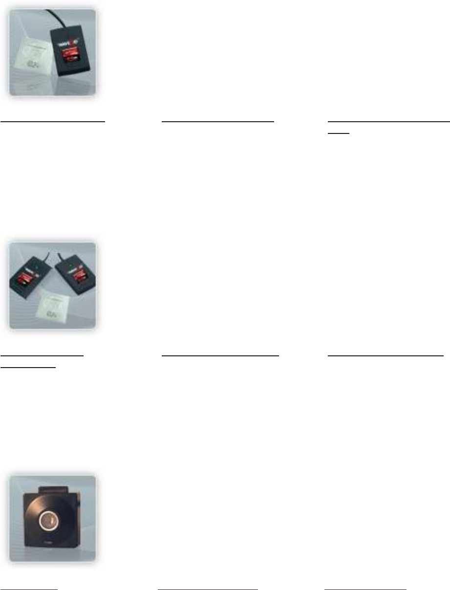
Other
Products
& Accessories
Sof
t
war
e
Developer’s
Kit
Allows independent
developer’s
to
use
their
application
to
read
proximity
access badge Read
ID data
of
more than
1
billion cards
in the field
PVC Label
Proximity Card
Credit card size
with paper
release liner,
500
cards
per
box
Proximity
Cards, Labels,
Key
Fobs
Complete selection
of various
manufacturers proximity
cards,
labels and key
fobs. Marked
with
data code and
ID
number
,
available
in
several
Wiegand
formats
pcProx
R
ead/W
rit
e
C
ontactles
s
Reads and
writes
directly
t
o
the
smart
cards
pcProx
Writer
and
Playback
Desk
t
op
read-only
f
or
iCLAS
S
and NXP
and smart
cards
pcProx Playback
Star
t
er
Kit
Plays back card sector
data
in
ASCII
or keystrokes
pcP
r
o
x
Sonar
Presence detector
c
onfigur
ed
as a
keyboard
PS/2
t
o
USB Power
Tap
Powers a USB RF IDeas
device
from
a PS/2
port
Mounting Brackets
F
urther
adjust
the standard
mounting
of the
device
angle
69
RF IDeas
Inc.
©
2013
RF IDeas.
All
rights
reserved.
Specifications subject
to
change
without notice.
Windows, Macintosh,
Solaris, Sun Ray and Linux are trademarks
of their
respective
companies.
All
other trademarks, service marks and product
or
service names are
property
of their
respective
owners.
Mention of third-party
products
is for
informational purposes only and constitutes neither an endorsement
nor a
recommendation.
RF
IDeas assumes no responsibility
with
regard
to the
performance
or
use
of
these
products.
All
understandings, agreements,
or
warranties,
if
any, take place directly between
the
vendors and
the
prospective
users.
Please feel free
to
call, e-mail
or visit our
web site
for
a
full list of
applications, products, configuration options,
supported
cards and
form factor
specifications. Our web site includes application videos,
support materials,
case studies
and
detailed information about
our
product
line.
Every
effort
has been made
to
ensure
that the
information
in this
manual
is
accurate.
RF IDeas
is not
responsible
for
printing
or
clerical
errors.
