RF LINK CPR9851S bluetooth module User Manual CPR9851S V2 1specificationx
RF-LINK INTERNATIONAL LIMITED bluetooth module CPR9851S V2 1specificationx
RF LINK >
Users Manual
1
Catalogue
版本说明 verisondescription.......................................................................................................................2
1.概述 overview................................................................................................................................................ 3
2.应用领域 application...................................................................................................................................3
3.功能架构 functionstructure.....................................................................................................................4
3.1 功能架构图 diagram............................................................................................................................4
3.2 功能描述 functiiondescription....................................................................................................4
4.性能参数 perfromanceparameter...............................................................................................................5
5.引脚功能说明(管脚分配图如附录 C)Pinsfunctiondescription(AppendixC)............................ 5
6.工作模式 workmode....................................................................................................................................... 6
7.注意事项 attention....................................................................................................................................... 7
附录 A:模块尺寸 modulesize........................................................................................................................9
附录 B:模块图像 modulepic........................................................................................................................10
附录 C:管脚分配 pinsdistribution..........................................................................................................11
附录 D:应用参考电路 referencedesign....................................................................................................12
User Guid
FCC ID: A5LCPR9851S

2
versiondescription
Version Updatecontent Updatetime Updateperson
Ver1.0 Released / /
Ver2.0
Unifiedspecification
format(includingthe
header/foot,fonts,
spacing,etc.)
2014.4.11 杨兰珍
Ver2.1 UpdatedICpackage 2014.07.21 温锦铎

3
1.Overview
CPR9851SisdesignedbasedonRDA5851SXchipset,ahigh
integrated,lowcostandlowpowerconsumptionwithstereofunction
BTmodule.Whichsupportcommunicationbytelephone,TFcard,FM,and
Lineinfunctions.MeetBlutooth2.1+EDRspecification.Toprovide
lowcosthighefficientstereotransmissionsolutionforcustomer.
2.Application
Thismoduleusedtotransmitmusicinshortdistance,which
directlylinkwithPC,phone,PDA,anddigitalproductsthoughBT.
Moreover,itintegratedwithFMandsupportautoplaymusicfromMMC
card.
1Singlechipsolution,integratedwithLinein,FM,IRcontrol,
TF/SDcardandUSBaudiocard.
2StereoBTheadset
3Wirelessmusictransmission
4.BTcardreader,BTdialer,BTcompanion,BTspeaker,ect.
4
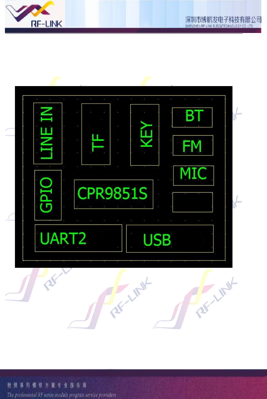
3.Functionstructure
3.1 Diagram
3.2Functiondescription
1)supportMP3,WMA,WAV,SBCformat
2)wirelessstereoaudiotransmission,bluetoothphone
3)FM
4)BTcardreader,asitsupportUSBhostfunction,soitcanread
CARD
EARPHONE
5
datafromSDorMMC.
5)stereoaudioline-ininput
6)remotecontrol
7)leftforADCbuttonandpoweronbuttonpins
8)UARTportforserialcommunication,andcancustomizeAT
communicationprotocol
9)integratedpowermanagementcircuit
10)highrateUARTinterfacefordebugorupdatesoftware
11)abundantIOportforapplicationextend
12)supportUSBaudio
13)supportSPPdatatrasmission
4.performanceparameter
BTversion BluetoothV2.1+EDR
Modulationsystem GFSK,π/4-DQPSK 和8DPSK
support HFP/HSP,OPP,A2DP/AVRCP,PBAPprofiles
sensitivity(0.1%BER) -82dBm
TXpower Meetclass2andclass3sendrequirement
Powersupply 3.2V~4.2V
Currentconsumptiion Regularwork45mA ,pause32mA
SNR 70dB
Worktemperature -20~+50 ℃
Modulesize 20.7mmx15mmx2.0mm
6
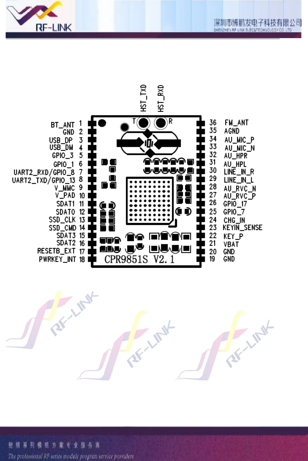
5.Pinsfunctiondescription(AppendixC)
pins name Functiondescription
1 BT_ANT BTantenna
2GND Groundconnection
3USB_DP D-
4 USB_DM D+
5 GPIO_3 GPIOport/IRreceiveport,pausebutton
6 GPIO_1 GPIOport,defaultTFcarddetective
7 UART2_RXD/GPIO_8 UART2serialportalsousedforGPIO,nopausefunction
8 UART2_TXD/GPIO_13 UART2nointerruptfunction
9 V_MMC TFcardpower
10 V_PAD 2.98Voutput
11 SDAT1 TFdataline
12 SDAT0 TFdataline
13 SSD_CLK TFclock
14 SSD_CMD TFwriteorreadcontrol
15 SDAT3 TFdataline
16 SDAT2 TFdataline
17 RESETB_EXT Resetport
18 PWRKEY_INT softwareswitch,highefficiency
19 GND Groundconnect
20 GND Groundconnect
21 VBAT Powerformodule3.4-4.2V
22 KEY_P ADCpressbutton
23 KEYIN_SENSE ADCpressbutton
24 CHG_IN internalpowercharging(askforextendexternalcircuit)
25 GPIO_7 GPIO,faultLINEDECT ,supportexternalsuspendfunction
26 GPIO_17 GPIO,noexternalsuspendfunction
27 AU_RCV_P Audiopositiveoutputpole
28 AU_RCV_N audiodifferentialoutputpole
29 LINE_IN_L AUXleftlinein
30 LINE_IN_R AUXrightlinein
31 AU_HPL leftsingle-endedsoundchanneloutput
32 AU_HPR rightsingle-endedsoundchanneloutput
33 AU_MIC_N MICdifferentialnegativeoutputpole
34 AU_MIC_P MICdifferentialpositiveoutputpole
35 AGND Analogground
7
36 FM_ANT FMantenna
6.Workmode
1)poweronwith3.7to4.2VDCdirectlyorUSBchargerfor5V
source.
2)ShortpressPWRbutton,whentheLED1andLED2flick
alternately,itmeansmatchcorrectly.
3)matchsuccessfullylasttime,itwillautomaticallymatchwhen
BTmodulepoweron.
4)ClosetheBTconnectionlasttime,BTmodulecanconnectwith
otherdeviceswhenBTmodulework.
5)AfteritconnectwithBTdevice,itcantransmitmusicthrough
BTdevice,andcontrolnextorlastmusic,increaseordecreasevolume,
pauseorcontinueplay,pressmodebuttontoenterTFFMline.Tosum
up,allbuttonfunctionscanconfigurethroughsoftware.
6)ItmatchswithphoneviaBT,shortpressPWRbuttontoconnect
orhangupthecallwhenyougetthephonecall.
7.Attentions
1)PCBlayout:LaygroundorrountingisnotallowedundertheBT

8
module’santenna.
2)Module’santennaneedputthesideofmotherboard,notallowed
toputnearoroverlapwithmetalmaterial.Suchasbattery,other
chip.
3)BTwirelessapplicationiseasilyaffectedbyexecrable
environment,becauseobstacleaswoodormetalwillobsorbwireless
signal,thedatatransmitdistancewillbeaffectedduring
application.
4)Donotembedinthemetalshield,becausewirelessRFsignal
willbeshieldedbymetalcover.
5)SIGmembershipandBQBcertification:AuthorizeSIGandBQB
ifuseBluetoothtrademark.

9
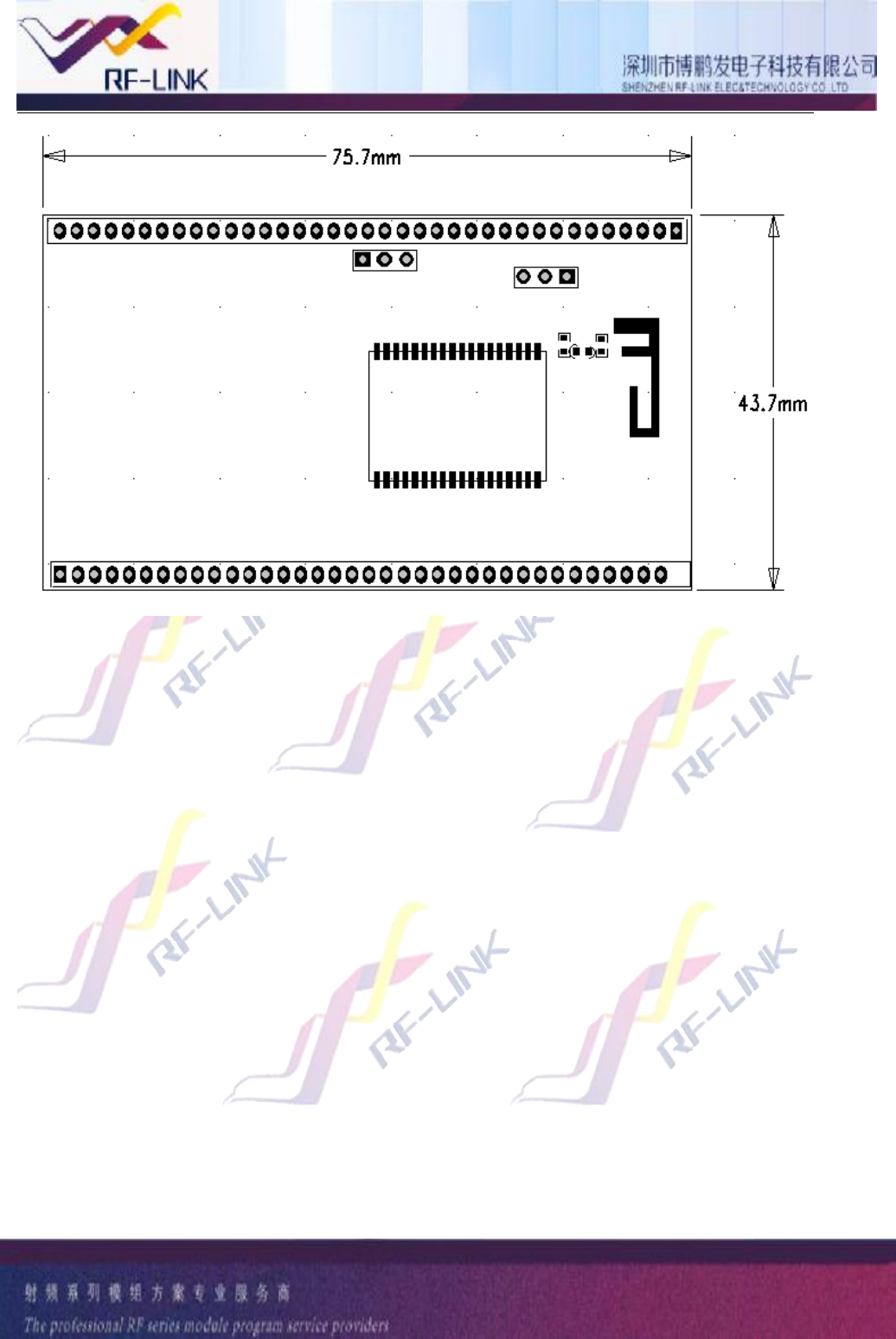
AppendixA:modulesize
Dimension&footprint
10
AppendixB:modulepic
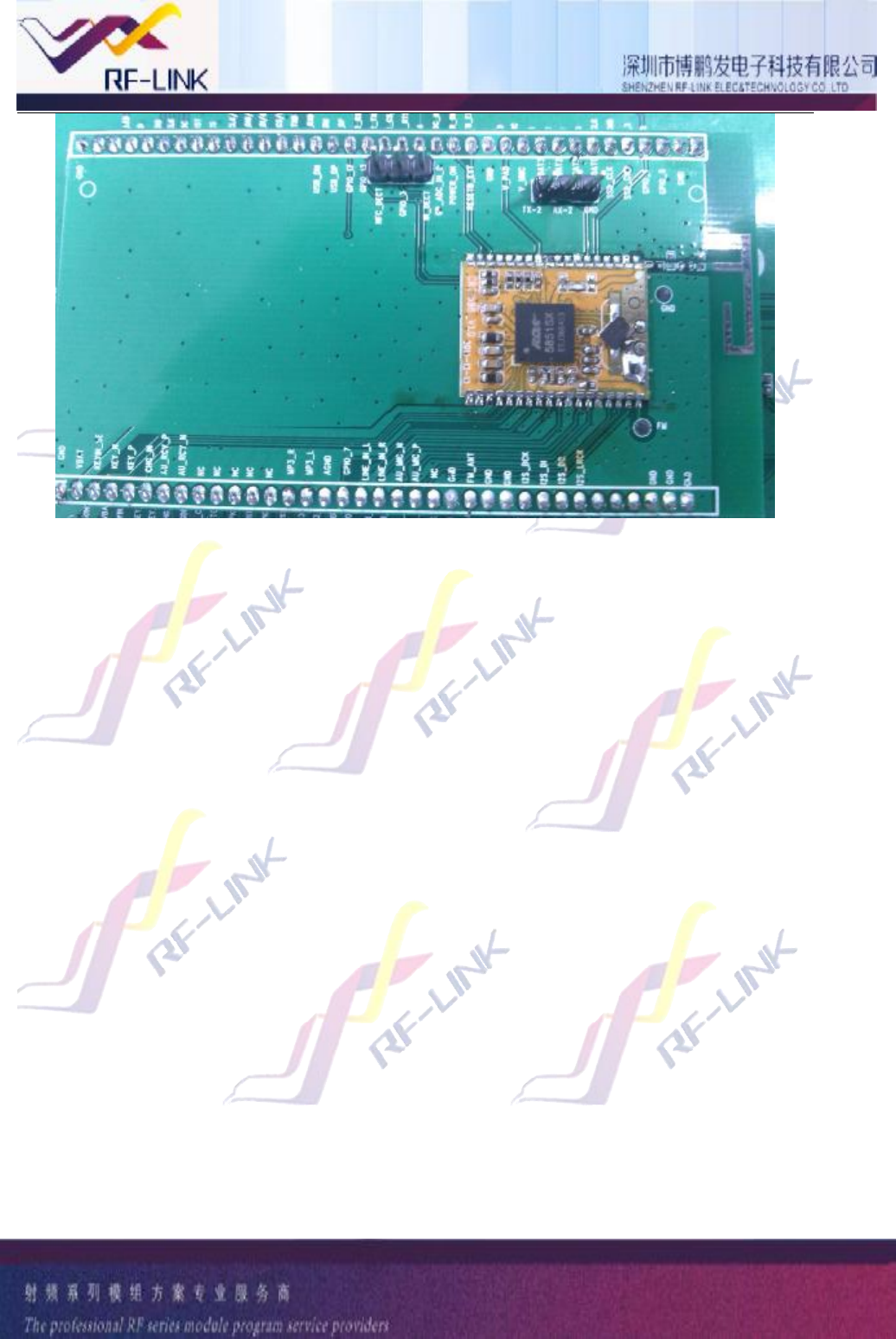
11
12
AppendixC:pinsarrangement
13
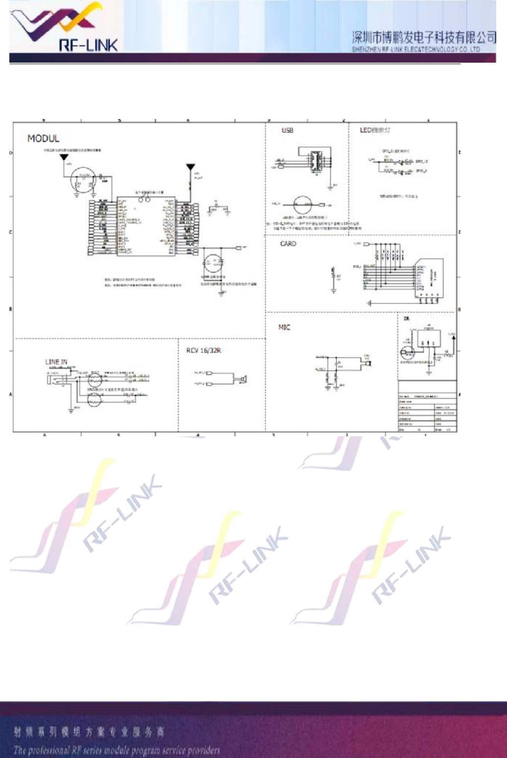
AppendixD:referencedesign

14
This device complies with part 15 of the FCC Rules. Operation is subject to the following two conditions:
(1) This device may not cause harmful interference, and (2) this device must accept any interference
received, including interference that may cause undesired operation.
Changes or modifications not expressly approved by the party responsible for compliance could void the
user's authority to operate the equipment.
NOTE: This equipment has been tested and found to comply with the limits for a Class B digital device,
pursuant to Part 15 of the FCC Rules. These limits are designed to provide reasonable protection
against harmful interference in a residential installation. This equipment generates, uses and can radiate
radio frequency energy and, if not installed and used in accordance with the instructions, may cause
harmful interference to radio communications. However, there is no guarantee that interference will not
occur in a particular installation. If this equipment does cause harmful interference to radio or television
reception, which can be determined by turning the equipment off and on, the user is encouraged to try to
correct the interference by one or more of the following
measures:
-- Reorient or relocate the receiving antenna.
-- Increase the separation between the equipment and receiver.
-- Connect the equipment into an outlet on a circuit different from that to which the receiver is connected.
-- Consult the dealer or an experienced radio/TV technician for help.
This modular complies with FCC RF radiation exposure limits set forth for an uncontrolled environment.
This transmitter must not be co-located or operating in conjunction with any other antenna or transmitter.
If the FCC identification number is not visible when the module is installed inside another device, then
the outside of the device into which the module is installed must also display a label referring to the
enclosed module. This exterior label can use wording such as the following: “Contains Transmitter
Module FCC ID:A5LCPR9851S Or Contains FCC ID:A5LCPR9851S”
when the module is installed inside another device, the user manual of this device must contain below
warning statements;
1. This device complies with Part 15 of the FCC Rules. Operation is subject to the following two
conditions:
(1) This device may not cause harmful interference.
(2) This device must accept any interference received, including interference that may cause undesired
operation.
2. Changes or modifications not expressly approved by the party responsible for compliance could void
the user's authority to operate the equipment.
The devices must be installed and used in strict accordance with the manufacturer's instructions as
described in the user documentation that comes with the product