RF WINDOW ICS-F0837 ICS-Digital Relay User Manual ICS F0837 v1 1
RF WINDOW Co.,Ltd. ICS-Digital Relay User Manual ICS F0837 v1 1
UserManual.wiki
>
RF WINDOW
>
ICS F0837 User Manual
user manual
Navigation menu
Upload a User Manual
Namespaces
Wiki Guide
HTML
PDF
Info
Views
User Manual
Discussion / Help
Navigation
![RF Window Co., Ltd. | 2 ICS Repeater ICS-W0837B User ManualICS-F0837 User manual/Confidential & Proprietary [ Table of Contents ] 1. System Overview ................................................................................................. 10 2. System Network Configuration ............................................................................ 11 2.1. Service for Network.............................................................................................. 11 2.2. NMS Network....................................................................................................... 12 3. System Specification............................................................................................ 13 3.1. System ................................................................................................................. 13 3.1.1. System Specification ....................................................................................... 13 3.2. System Configuration........................................................................................... 17 3.3. Environment Specification.................................................................................... 18 3.4. Mechanical Specification...................................................................................... 18 4. Housing................................................................................................................ 19 4.1. Housing Configuration ......................................................................................... 19 4.1.1. System ............................................................................................................ 19 4.1.2. System Block Plan .......................................................................................... 21 4.1.3. System External Connector Plan .................................................................... 22 5. Main Module Configuration.................................................................................. 24 5.1. ICM (Interference Cancellation Module) .............................................................. 24 5.1.1. ICM 24 5.2. Filter ..................................................................................................................... 25 5.2.1. Donor & Service Duplexer............................................................................... 25 5.3. Dual HPA ............................................................................................................. 26 5.3.1. Dual HPA......................................................................................................... 26](https://usermanual.wiki/RF-WINDOW/ICS-F0837/User-Guide-1243958-Page-3.png)
![RF Window Co., Ltd. | 6 ICS Repeater ICS-W0837B User ManualICS-F0837 User manual/Confidential & Proprietary [List of Figures] [FIGURE - 1] SYSTEM NETWORK CONFIGURATION 1 ................................................... 11 [FIGURE - 2] SYSTEM NETWORK CONFIGURATION 2 ................................................... 11 [FIGURE - 3] NMS NETWORK CONFIGURATION.............................................................12 [FIGURE - 4] FRONT AND SIDE VIEW...............................................................................19 [FIGURE - 5] REAR VIEW...................................................................................................20 [FIGURE - 6] SYSTEM BLOCK PLAN.................................................................................21 [FIGURE - 7] SYSTEM EXTERNAL CONNECTORS..........................................................22 [FIGURE - 8] DOWN LINK/UP LINK ICM ............................................................................24 [FIGURE - 9] DONOR & SERVICE DUPLEXER .................................................................25 [FIGURE - 10] DOWN LINK PAU ........................................................................................26 [FIGURE - 11] POWER SUPPLY.........................................................................................27 [FIGURE - 12] INTERFACE.................................................................................................28 [FIGURE - 13] RCU VFD MENU TREE...............................................................................30 [FIGURE - 14] KEY-PAD......................................................................................................33 [FIGURE - 15] GUI MAIN WINDOW...................... 오류! 책갈피가 정의되어 있지 않습니다. [FIGURE - 16] GUI COMMUNICATION SETUP.... 오류! 책갈피가 정의되어 있지 않습니다. [FIGURE - 17] GUI COMMUNICATION STATUS WINDOW .. 오류! 책갈피가 정의되어 있지 않습니다. [FIGURE - 18] GUI SYSTEM STATUS .................. 오류! 책갈피가 정의되어 있지 않습니다. [FIGURE - 19] GUI PSU STATUS.......................... 오류! 책갈피가 정의되어 있지 않습니다. [FIGURE - 20] GUI DOWN LINK SETUP STATUS 오류! 책갈피가 정의되어 있지 않습니다. [FIGURE - 21] GUI UP LINK SETTING STATUS .. 오류! 책갈피가 정의되어 있지 않습니다. [FIGURE - 22] GUI WCDMA(3G) CONTROL WINDOW오류! 책갈피가 정의되어 있지 않습](https://usermanual.wiki/RF-WINDOW/ICS-F0837/User-Guide-1243958-Page-7.png)
![RF Window Co., Ltd. | 7 ICS Repeater ICS-W0837B User ManualICS-F0837 User manual/Confidential & Proprietary니다. [FIGURE - 23] FIRMWARE DOWNLOAD WINDOW..오류! 책갈피가 정의되어 있지 않습니다. [FIGURE - 24] GUI DEBUG WINDOW .................. 오류! 책갈피가 정의되어 있지 않습니다. [FIGURE - 25] SIGNAL STATUS WINDOW .......... 오류! 책갈피가 정의되어 있지 않습니다. [FIGURE - 26] PROCESS OF ICS REPEATER SETUP AND INSTALLATION ...................40](https://usermanual.wiki/RF-WINDOW/ICS-F0837/User-Guide-1243958-Page-8.png)
![RF Window Co., Ltd. | 8 ICS Repeater ICS-W0837B User ManualICS-F0837 User manual/Confidential & Proprietary [ List of Tables ] [TABLE - 1] RF SYSTEM SPECIFICATION.........................................................................16 [TABLE - 2] SYSTEM CONFIGURATION............................................................................ 18 [TABLE - 3] ENVIRONMENT SPECIFICATION...................................................................18 [TABLE - 4] MECHANICAL SPECIFICATION......................................................................18 [TABLE - 5] MODULES........................................................................................................21 [TABLE - 6] SYSTEM EXTERNAL CONNECTORS ............................................................22 [TABLE - 7] MECHANICAL SPECIFICATION......................................................................23 [TABLE - 8] INTERFACE FEATURES .................................................................................29 [TABLE - 9] RCU STATUS CONTROL DETAILS.................................................................33 [TABLE - 10] KEY FEATURE...............................................................................................33 [TABLE - 11] GUI PC REQUIREMENT.................. 오류! 책갈피가 정의되어 있지 않습니다. [TABLE - 12] REPEATER STATUS DETAILS ........ 오류! 책갈피가 정의되어 있지 않습니다. [TABLE - 13] SYSTEM MONITORING .................. 오류! 책갈피가 정의되어 있지 않습니다. [TABLE - 14] PSU MONITORING.......................... 오류! 책갈피가 정의되어 있지 않습니다. [TABLE - 15] DOWN LINK MONITORING............. 오류! 책갈피가 정의되어 있지 않습니다. [TABLE - 16] UP LINK MONITORING ................... 오류! 책갈피가 정의되어 있지 않습니다. [TABLE - 17] SYSTEM CONTROL ITEM............... 오류! 책갈피가 정의되어 있지 않습니다. [TABLE - 18] DOWN LINK CONTROL ITEM ......... 오류! 책갈피가 정의되어 있지 않습니다. [TABLE - 19] UP LINK CONTROL ITEM ............... 오류! 책갈피가 정의되어 있지 않습니다. [TABLE - 20] SYSTEM CONFIGURATION..........................................................................38 [TABLE - 21] AC CONNECTOR PIN ASSIGN ..................................................................... 38 [TABLE - 22] SYSTEM CONNECTION PORT.....................................................................39 [TABLE - 23] RF MONITOR PORT......................................................................................39](https://usermanual.wiki/RF-WINDOW/ICS-F0837/User-Guide-1243958-Page-9.png)
![RF Window Co., Ltd. | 9 ICS Repeater ICS-W0837B User ManualICS-F0837 User manual/Confidential & Proprietary[TABLE - 24] DOWN LINK / UP LINK ALARM HANDLING .................................................42 [TABLE - 25] ENVIRONMENT ALARM................................................................................42](https://usermanual.wiki/RF-WINDOW/ICS-F0837/User-Guide-1243958-Page-10.png)
![RF Window Co., Ltd. | 11 ICS Repeater ICS-W0837B User ManualICS-F0837 User manual/Confidential & Proprietary2. System Network Configuration 2.1. Service for Network ICS-F0837 can provides Cell Coverage to a Node-B with using PAU and it is for expansion of WCDMA Cell Coverage. The System Network Configuration of ICS-F0837 is shown as below αβγαT1/E1WirelessRepeater CellRepeaterαβγαβγαT1/E1WirelessRepeater CellRepeater [Figure - 1] System Network Configuration 1 αβγαT1/E1Optic FiberRepeater CellRepeaterWireless Repeater αβγαβγαT1/E1Optic FiberRepeater CellRepeaterWireless Repeater [Figure - 2] System Network Configuration 2](https://usermanual.wiki/RF-WINDOW/ICS-F0837/User-Guide-1243958-Page-12.png)
![RF Window Co., Ltd. | 12 ICS Repeater ICS-W0837B User ManualICS-F0837 User manual/Confidential & Proprietary Input level of ICS-F0837 is air interfaced with RF signal of WCDMA transferred from Node-B and mobile through Donor and Service Antenna. The system consists of ICM that cancels feedback signals, RF signal amplifier, monitoring and control processor, and modem to operate with NMS (Optional). The system has features that the Node-B RF signal through the donor antenna, ICM and amplified by PAU of down link to pass the signals to service antenna. Also, it takes the mobile input signal through service antenna, ICM and amplifier to pass the signals to donor antenna. ICM consists of two parts, RF part and Digital part and ICM cancels feedback signals for DL and UL. DL HPA consists of AMP block that amplifies RF signals and Controller block that monitor and controls Amp block. 2.2. NMS Network ICS-F0837 can be connected with WRCS which has been already operating. The Connection of between WRCS and ICS-F0837 meets the standard of service provider. [Figure - 3] NMS Network Configuration](https://usermanual.wiki/RF-WINDOW/ICS-F0837/User-Guide-1243958-Page-13.png)
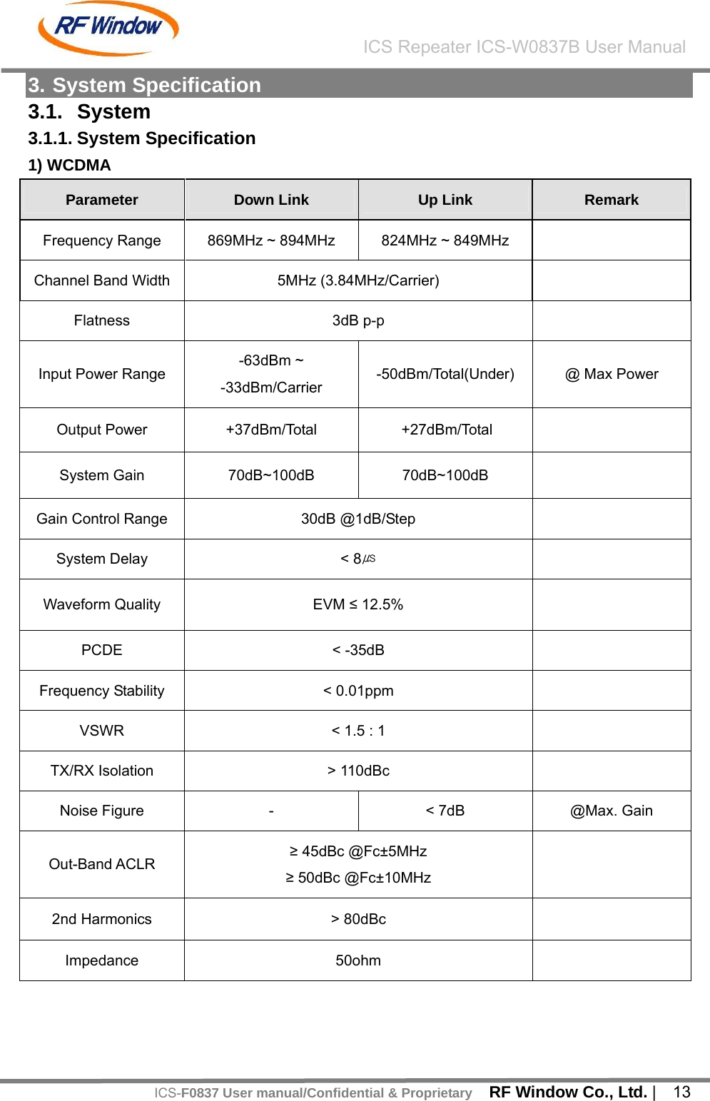
![RF Window Co., Ltd. | 16 ICS Repeater ICS-W0837B User ManualICS-F0837 User manual/Confidential & ProprietaryParameter Condition Specification Remark Cancellation Window Length DL, UL 6 us Gain Re-Tracking Time after reset Target Gain ±1dB < 10 Sec Isolation Sensing Range 10dB < Gain < 10dB Accuracy ±1 b) ICS Fading Performance Specification Gain Feddback Condition (Multi-path 10) Specification Remark G = I + 10dB Static Rho>0.97 Gain Variation : < ±2dB No FadingG = I 5Hz Rho>0.97 Gain Variation : < ±2dB General Operating [Table - 1] RF System Specification](https://usermanual.wiki/RF-WINDOW/ICS-F0837/User-Guide-1243958-Page-17.png)
![RF Window Co., Ltd. | 18 ICS Repeater ICS-W0837B User ManualICS-F0837 User manual/Confidential & ProprietaryModem for remote Include / one package [Table - 2] System Configuration 3.3. Environment Specification Item Specification Remark AC Power AC 100 ~ 260V DC In Power DC Input Voltage : +24VDC(+21VDC ~ 29.5VDC) Option Consumption power Under 200W Operating Temperature -30°C ~ +55°C Operating Humidity 5% ~ 95% Storage temperature -40 ~ +80°C(5~95% RH) Ingress protection IP65 [Table - 3] Environment Specification 3.4. Mechanical Specification Item Details Size 305(W) X 565(H) X 194(D) Weight Under 30Kg Convection type Natural convection Mounting Wall & poll (modified based on user request) Cabinet type Outdoor (compliant with IP 65) [Table - 4] Mechanical Specification](https://usermanual.wiki/RF-WINDOW/ICS-F0837/User-Guide-1243958-Page-19.png)
![RF Window Co., Ltd. | 19 ICS Repeater ICS-W0837B User ManualICS-F0837 User manual/Confidential & Proprietary4. Housing 4.1. Housing Configuration 4.1.1. System [Figure - 4] Front and Side View](https://usermanual.wiki/RF-WINDOW/ICS-F0837/User-Guide-1243958-Page-20.png)
![RF Window Co., Ltd. | 20 ICS Repeater ICS-W0837B User ManualICS-F0837 User manual/Confidential & Proprietary [Figure - 5] Rear View](https://usermanual.wiki/RF-WINDOW/ICS-F0837/User-Guide-1243958-Page-21.png)
![RF Window Co., Ltd. | 21 ICS Repeater ICS-W0837B User ManualICS-F0837 User manual/Confidential & Proprietary 4.1.2. System Block Plan [Figure - 6] System Block Plan No. Module Name 1 ICM 2 INTERFACE (with Modem) 3 DUPLEXER (TOP) 4 DUAL HPA (BOTTOM) 5 PSU 6 UPS Interface [Table - 5] Modules ① ② ③ ④ ⑤](https://usermanual.wiki/RF-WINDOW/ICS-F0837/User-Guide-1243958-Page-22.png)
![RF Window Co., Ltd. | 22 ICS Repeater ICS-W0837B User ManualICS-F0837 User manual/Confidential & Proprietary 4.1.3. System External Connector Plan [Figure - 7] System External Connectors No. Name 1 AC Input Port 2 Bluetooth Modem port 3 Donor Antenna Port 4 Service Antenna Port [Table - 6] System External Connectors ① ② ④③](https://usermanual.wiki/RF-WINDOW/ICS-F0837/User-Guide-1243958-Page-23.png)
![RF Window Co., Ltd. | 23 ICS Repeater ICS-W0837B User ManualICS-F0837 User manual/Confidential & Proprietary Item Specification Size 305mm(W) X 565mm(H) X 194mm(D) Material Aluminum(AL5052, AL6063) for rust protection Cooling Natural Convection with Heat Sink Locks 2 EA on the side of cabinet Antenna Port 1. Location : 2 Ports at the under of housing 2. Connector Type : DIN Type Modem Port 1. Location : 1 Port at the lower of housing 2. Connector Type : SMA Type Ground M5 2Hole Environmental Condition 1. Water proof : outdoor type 2. ∆T : within 20℃ 3.Vibration : 1G, 10~150Hz, 0.1oct/min, XYZ [Table - 7] Mechanical Specification](https://usermanual.wiki/RF-WINDOW/ICS-F0837/User-Guide-1243958-Page-24.png)
![RF Window Co., Ltd. | 24 ICS Repeater ICS-W0837B User ManualICS-F0837 User manual/Confidential & Proprietary5. Main Module Configuration 5.1. ICM (Interference Cancellation Module) ICM is located between Antenna connector and Dual HPA. It is designed to resolve the problems caused by near-far among operators and LNA built-in to amplify a low noise and make satisfied stop band rejection. It operates to transmit signals to Dual HPA and to maintain signal regularly input to final amplifier after determining gain to need for system after conversing signal processed from DSP to frequency. It is also operated the function of Remote Control Unit through INTERFACE. 5.1.1. ICM [Figure - 8] Down Link/Up Link ICM](https://usermanual.wiki/RF-WINDOW/ICS-F0837/User-Guide-1243958-Page-25.png)
![RF Window Co., Ltd. | 25 ICS Repeater ICS-W0837B User ManualICS-F0837 User manual/Confidential & Proprietary 5.2. Filter It is 25MHz Band Pass Filter(DL:869~894,UL:824~849) and consists of Service and Donor. Service Duplexer has 40dB Coupler to monitor Output power and Donor Duplexer has 30dB Coupler to monitor Input power. Hence it can enable to measure the signal level and to observe its specification. 5.2.1. Donor & Service Duplexer [Figure - 9] Donor & Service Duplexer](https://usermanual.wiki/RF-WINDOW/ICS-F0837/User-Guide-1243958-Page-26.png)
![RF Window Co., Ltd. | 26 ICS Repeater ICS-W0837B User ManualICS-F0837 User manual/Confidential & Proprietary 5.3. Dual HPA Down link PAU receives the signal from ICM and amplifies it finally. This is designed to keep up the stable output power of system in order to satisfy electrical specification of system output power. It is a Linear Amp with output power 8W(total power) in down link, 1W in up link (total power) and executes Drive Amp feature simultaneously while Gain is 47dB in Down Link, 33dB in Up Link. Input Voltage is 27VDC and has alarm feature for over power, over temperature, and VSWR. It has the same mount hole which can be applied for the same specification and configuration according to output power amount (8W/1W) and HPA manufacturer. 5.3.1. Dual HPA [Figure - 10] Down Link PAU](https://usermanual.wiki/RF-WINDOW/ICS-F0837/User-Guide-1243958-Page-27.png)
![RF Window Co., Ltd. | 27 ICS Repeater ICS-W0837B User ManualICS-F0837 User manual/Confidential & Proprietary 5.4. Power Supply PSU is designed to input AC 100~260V and to output DC +27V and +12V. +27V and Battery is designed for the Pin short protection by inferior and can provide a stable power supply. It also has Back-Up Battery terminals so that the service can be provided even if there is power shortage. 5.4.1. Power Supply [Figure - 11] Power Supply](https://usermanual.wiki/RF-WINDOW/ICS-F0837/User-Guide-1243958-Page-28.png)
![RF Window Co., Ltd. | 28 ICS Repeater ICS-W0837B User ManualICS-F0837 User manual/Confidential & Proprietary 5.5. INTERFACE User can monitor and control the repeater by VFD and Keypad. Interface board consists of 40Pin connector for communication with ICM, 16pin connector for communication with Dual HPA, 24pin connector for communication with Interface board receives electrical power from PSU and distributed the power to all of active module except Dual HPA. It also can communicate with all of active module. Debug port is designed based on USB connection 5.5.1. INTERFACE [Figure - 12] INTERFACE VFD KEY-PAD LED MODEM ANTENNA PORT BLUETOOTH ANTENNA PORT USB ICM INTERFACE POWER INTERFACEHPA INTERFACE UPS Alarm INTERFACE UPS Alarm INTERFACE](https://usermanual.wiki/RF-WINDOW/ICS-F0837/User-Guide-1243958-Page-29.png)
![RF Window Co., Ltd. | 29 ICS Repeater ICS-W0837B User ManualICS-F0837 User manual/Confidential & ProprietaryTerm Feature VFD Monitor and check the status KEY-PAD Check and control the status LED Check the status of Module Modem Ant. Modem Antenna connection Port Bluetooth Ant. Bluetooth Modem Antenna connection Port USB GUI Port, System check with USB, PC Power Supply ICM, INTERFACE, reverse Dual HPA power PSU Status Status information of Power Supply Unit Module Interface ICM, Dual HPA, Modem Power supply/ Data Interface [Table - 8] INTERFACE Features](https://usermanual.wiki/RF-WINDOW/ICS-F0837/User-Guide-1243958-Page-30.png)
![RF Window Co., Ltd. | 31 ICS Repeater ICS-W0837B User ManualICS-F0837 User manual/Confidential & Proprietary 5.5.2.2. RCU status control menu RCU status control menu Item Details Remark “ Fwd Status “ ” ICS : [Normal] “ “ Fwd Status “ “ OUTPWR : 000dBm” “ Fwd Status “ “ INPWR : -000dBm” “ Fwd Status “ “ ISO. : 000dB” “ Fwd Status “ “ GAINMODE : [GAIN]dB>” Down Link GAIN setup Mode [OFF]/[GAIN] “ Fwd Status “ “ GAIN : 000dB>” Down Link GAIN Setup Mode “ Fwd Status “ “ATTN : 000dB>” Down Link Attenuator Setup Mode “ Fwd Status “ “ HIGH : [Normal]” “FWD Status” “ Fwd Status “ “ LOW : [Normal]” “ Rvs Status “ ” ICS : [Normal] “ “ Rvs Status “ “ OUTPWR : 000dBm” “ Rvs Status “ “ INPWR : -000dBm” “ Rvs Status “ “ ISO. : 000dB” “ Rvs Status “ “ GAINMODE : [GAIN]dB>” Up Link GAIN Setup Mode [OFF]/[GAIN]/[BAL] “RVS Status” “ Rvs Status “ “ GAIN : 000dB>” Up Link GAIN Setup Mode](https://usermanual.wiki/RF-WINDOW/ICS-F0837/User-Guide-1243958-Page-31.png)
![RF Window Co., Ltd. | 32 ICS Repeater ICS-W0837B User ManualICS-F0837 User manual/Confidential & Proprietary“ Rvs Status “ “ ATTN : 000dB>” Up Link Attenuator Setup Mode “ Rvs Status “ “ BAL : 000dB>” Up Link Balance Setup Mode “ Rvs Status “ “ HIGH : [Normal]” “ Fwd AMP Status “ “ OVERPWR : [NORMAL] ” “ Fwd AMP Status “ “ HI. TEMP : [NORMAL]” “ Fwd AMP Status “ “ VSWR : [NORMAL]” “ Fwd AMP Status “ “ DC : [NORMAL]” “ Fwd AMP Status “ “ Device : [NORMAL]” “FWD AMP Status” “ Fwd AMP Status “ “ Amp : [ ON ]>” Down Link Amplifier On/Off Setup Mode “RVS AMP Status” “ Rvs AMP Status “ “Amp : [ON]>” Up Link Amplifier On/Off Setup Mode “ Environment ” “ DOOR : [OPEN]” “ Environment ” “ TEMP : 000 ℃” “ Environment ” “ AC : [NORMAL]” “ Environment ” “ DC : [NORMAL]” “ Environment ” “ BATT : [NOTUSE]>” Battery Use Setup Mode (Unistall, 29V embedded) “ Environment ” “ FAMODE : [MANUAL]>” FA Mode Setup Mode Manual (FA1~FA4), Auto “Environment” “ Environment ” “ FAN : [MANUAL]>”](https://usermanual.wiki/RF-WINDOW/ICS-F0837/User-Guide-1243958-Page-32.png)
![RF Window Co., Ltd. | 33 ICS Repeater ICS-W0837B User ManualICS-F0837 User manual/Confidential & Proprietary“ Environment ” “ SLANT : [RESET]>” Slop Sensor Setup Reset “ Environment ” “ SLANT : [NORMAL]>” [Table - 9] RCU Status Control Details 5.5.3. KEY-PAD Menu Up Down Enter ESC [Figure - 14] KEY-PAD KEY-PAD uses 5 keys as above. Each meaning and operation is as below. The setup Mode is only in P#02 and it can change a mode by setup. In P#02, a menu which can be setup is displayed as ‘>’ Key Step Status Mode Setup Mode P#00 Move to P#01 N/A P#01 Move to P#00 N/A Menu P#02 Move to P#00 Move to P#00 P#00 N/A N/A P#01 Upper menu of P#01 N/A Up P#02 Upper menu of P#02 On or Increase P#00 N/A N/A P#01 Lower menu of P#01 N/A Down P#02 Lower menu of P#02 Off or Decrease P#00 Password window if press for 2 sec N/A P#01 Move to P#02 N/A Enter P#02 switch over to MoPe on setting menu Setting Value P#00 N/A N/A P#01 Move to P#00 N/A Esc P#02 Move to P#01 Cancel setiting [Table - 10] Key Feature](https://usermanual.wiki/RF-WINDOW/ICS-F0837/User-Guide-1243958-Page-33.png)
![RF Window Co., Ltd. | 38 ICS Repeater ICS-W0837B User ManualICS-F0837 User manual/Confidential & Proprietary7. System Installation and Setup 7.1. Installation 7.1.1. Configuration Item Specification Repeater Cabinet ICS-F0837 AC & UPS Connector MS3106A-20-18(9Pin Female) Quick manual User Manual [Table - 11] System Configuration AC & UPS Connector MS3106A-20-18(9Pin Female) Pin A : SERVICE_ALM_A Pin B : AC_NUT Pin C : LOW BATT_ALM_B Pin D : ON BATT_ALM_A Pin E : ON BATT_ALM_B Pin F : GND Pin G : LOW BATT_ALM_A Pin H : SERVICE_ALM_B Pin I : AC_HOT [Table - 12] AC Connector Pin Assign 7.1.2. Installation - Locate repeater at necessary place and fix the bracket - Connector both antennas to Antenna Port (DIN - Type Female Connector) - Ground repeater - Supply the Electrical Power (AC100~260V) - Verify if Main Power LED if the connection is correct (Extension code can be used if necessary, not included) - Port Connection to Repeater is as follows Item Function](https://usermanual.wiki/RF-WINDOW/ICS-F0837/User-Guide-1243958-Page-38.png)
![RF Window Co., Ltd. | 39 ICS Repeater ICS-W0837B User ManualICS-F0837 User manual/Confidential & ProprietaryAC IN B : AC 100V~260V+ I : AC 110V~260V- F : GND Modem Port Tx/Rx Donor Port TX Input / RX Output Service Port TX Output / RX Input [Table - 13] System Connection Port 7.1.3. Check List before operation - Verify if all the connections are correct including Power Cable, RF Cables, Ground and so on. - Verify if Power Box (100~260V) is connected correctly. - Verify if RF Cables have correct connection regarding block diagram. - Verify if each module power and data cable have correct connection - Verify if Connection with Antennas is correct. 7.1.4. RF Monitor Port Donor Antenna Service Antenna TX(To BTS) RX(from BTS) TX(To Mobile) RX(From Mobile) 15 dB Coupling 30 dB Coupling 40 dB Coupling - [Table - 14] RF Monitor Port](https://usermanual.wiki/RF-WINDOW/ICS-F0837/User-Guide-1243958-Page-39.png)
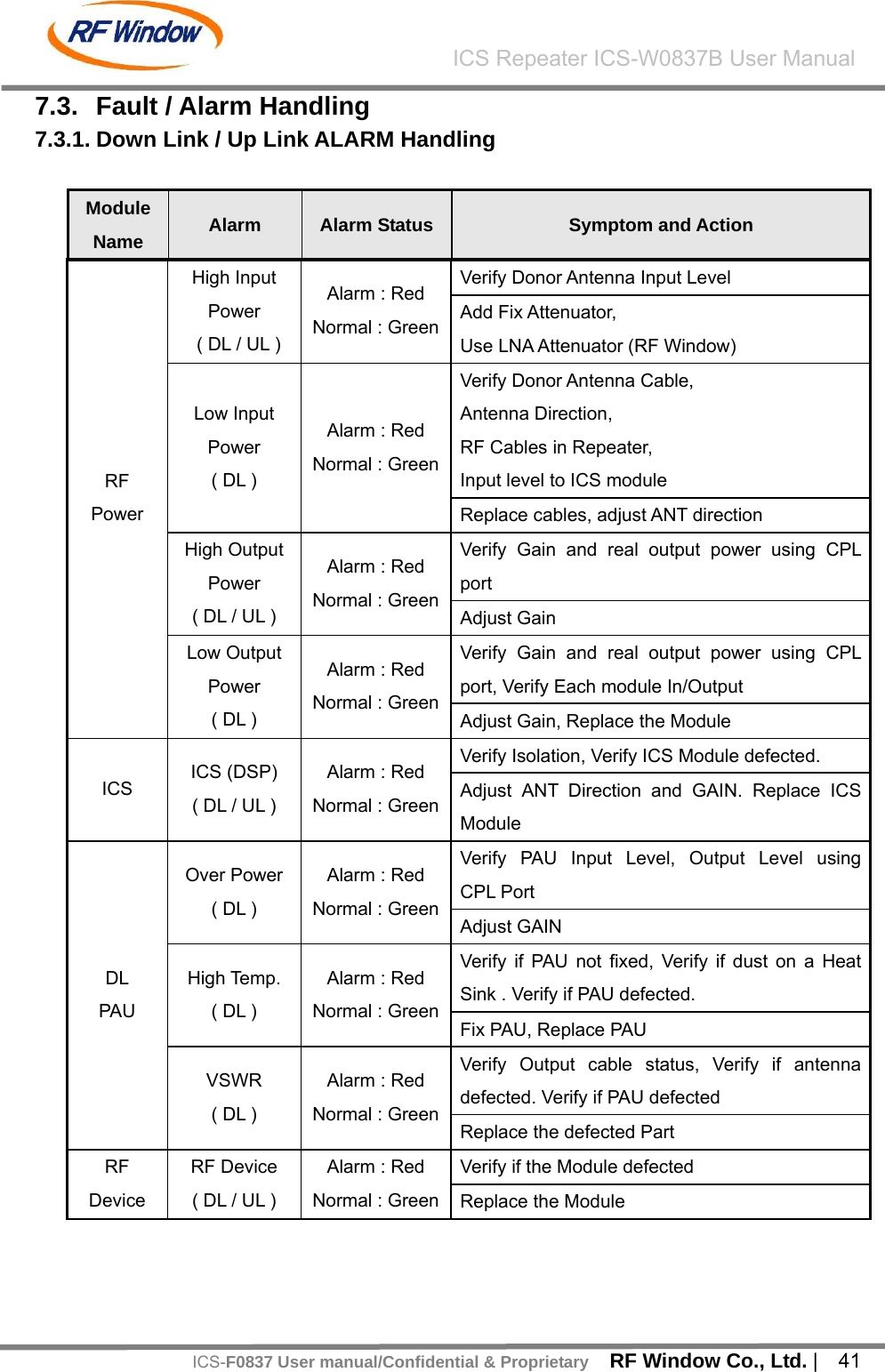
![RF Window Co., Ltd. | 42 ICS Repeater ICS-W0837B User ManualICS-F0837 User manual/Confidential & ProprietaryUL PAU PAU ( UL ) Alarm : Red Normal : GreenVerify if PAU defected. Cable Connection Status Replace the Module [Table - 15] Down Link / Up link Alarm Handling 7.3.2. Environment Alarm Item Alarm Status Symptoms and Actions Remark DOOR Status, DOOR SW operation Check Door Open Alarm Alarm : Red Normal : Green DOOR Lock and Updating SW Verify AC Voltage AC Alarm Alarm : Red Normal : Green Re-construct AC Power Verify if PSU output is 27V DC Alarm Alarm : Red Normal : Green Replace PSU Verify Housing Temp. Housing Tem p Alarm Alarm : Red Normal : Green [Table - 16] Environment Alarm](https://usermanual.wiki/RF-WINDOW/ICS-F0837/User-Guide-1243958-Page-41.png)