RFI Technology RFI-001 Wireless System for POS and Kitchen Printer User Manual FCC 2
RFI Technology Company Limited. Wireless System for POS and Kitchen Printer FCC 2
User Manual
SPRINTER Wireless System
User Manual
PWR/RT
KP1
KP2
KP3
KP4
PWR/RT
KP1
KP2
KP3
KP4
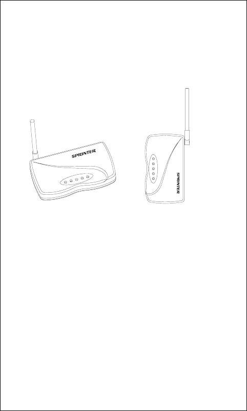
1. General Description
ECR/POS MODULE (POS Module)
- It is connected to the ECR or POS.
-
4 × RJ45 sockets for connections to ECR or POS Serial Ports by
RJ45/DB9 cable.
- 1 × DC jack for power input
- 1 × Red LED for Power and RF Status.
- 4 × Green LEDs to indicate Data Port Status.
- 1 × Push Switch to enter Register Mode.
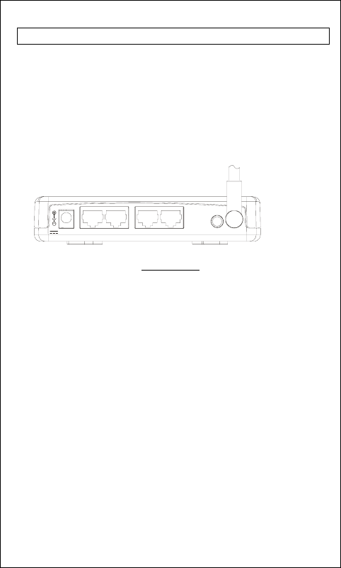
POS Module
1
DC 5V K 1P LEARNKP2 KP3 KP4
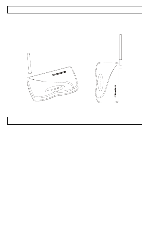
2. Placement Orientation
SPRINTER can be placed on any flat surface or mounted on the
wall. In either case, the antenna must be set upward for better
reception of signal.
3. Checklist for unpacking
Before start to install the SPRINTER system, please check the
items listed below:
POS Module Pack:
- 1 × POS Module
- 1 × Cable with RJ45/DB9 Connector
- 1 × AC/DC adaptor
If any thing missed, contact your dealer for supplement.
2
PWR/RT
KP1
KP2
KP3
KP4
PWR/RT
KP1
KP2
KP3
KP4

4. Installation
Step 1 – Setup the Serial Port on your ECR/POS and Printer
The Serial port of the ECR/POS and Printer must be set as below:
- Baud Rate: 9600 bps
- Date length: 8 Bit
- Parity: None
- Stop Bit: 1 or more
- Handshaking: Hardware control (DTR/DSR)
Step 2 - Connecting the Modules
POS Module
It is simply connecting the POS module to ECR or POS serial port by
the RJ45/DB9 cable. If you have more than one Kitchen Printer, you
just need to purchase additional RJ45/DB9 cables from your dealer for
connecting the modules to ECR or POS. The Port Number on the POS
Module corresponds to the ID of the Kitchen Printer:
KP 1 Æ Kitchen Printer ID 1,
KP 2 Æ Kitchen Printer ID 2,
KP 3 Æ Kitchen Printer ID 3,
KP 4 Æ Kitchen Printer ID 4,
Step 3 – Connecting the Power
Before power up the SPRINTER system, all ECR, POS or
Kitchen Printers should be switched on in advance.
Plug the AC/DC adapter to the wall outlet. Then, connect the adapter
DC plug to the module’s DC input jack.
A self-test will be run automatically. The Power LED (Red) and the
Data LED (Green) will flash once. If no error found, the Power LED
will be stay on and other LEDs will be off. The system is ready to go!
If error is found, all LEDs will be flashing and long beep sound will
be heard. Unplug the power and plug in again. If still has error,
contact your dealer. If both the LED and buzzer back to normal
indications, continue the Register process in Step 6.
3
KP 1
KP 3
KP 2 KP 4

5. LED & Buzzer Indications
Status Power/RF
LED
Data LED Buzzer Remark
POS
Module
Ready Mode Steady ON OFF Silence No data in
processing.
Transferring
Data
Steady ON Flashing
Randomly
Silence Printing in
progress.
Printer error Stead ON Stead ON Beep twice
after time out.
Paper out, Printer
buffer full, or
Printer not ready.
RF Error Flash for
5 seconds
Stead ON Beep twice. RF error
during transmission.
POS ID error Flashing Flashing Continuous
Beep sounds
Reset the power
and redo the
Register procedure
again. If error still
exists, contact your
dealer.
7
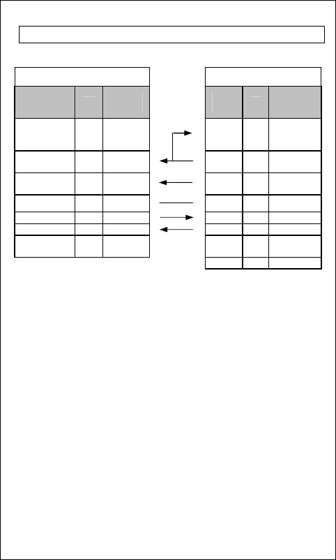
6. Cable connections
To ECR/POS Serial Port To SPRINTER POS Unit
DB 9
(Female) Pin
Description
I/O DB9F
Pin # RJ45
Pin # I/O RJ45 Pin
Description
Data Terminal
Ready (DTR) O 4
1 I
Data Set
Ready
(DSR)
Clear to Send
(CTS) I 8
2 O
Request to
Send (RTS)
Data Set
Ready (DSR) I 6
3 O
Data Terminal
Ready (DTR)
Signal GND - 5 4 - Signal GND
TxData O 3
5 I Rx Data
RxData I 2 6 O Tx Data
Request to
Send (RTS) O 7 7 -
No Connection
8 - No Connection
*All the information on this manual is subjected to change without
prior notice.
8

Caution
Modifications not authorized by the manufacturer may void users
authority to operate this device.
NOTE: This equipment has been tested and found to comply with
the limits for a class B digital device, pursuant to Part 15 of the
FCC Rules. These limits are designed to provide reasonable
protection against harmful interference in a residential
installation. This equipment generates, uses and can radiate radio
frequency energy and, if not installed and used in accordance with
the instructions, may cause harmful interference to radio
communications. However, there is no guarantee that interference
will not occur in a particular installation. If this equipment does
cause harmful interference to radio or television reception, which
can be determined by turning the equipment off and on, the user is
encouraged to try and to correct the interference by one or more
of the following measures:
-- Reorient or relocate the receiving antenna.
-- Increase the separation between the equipment and receiver.
-- Connect the equipment into an outlet on a circuit different from
that to which the receiver is connected.
-- Consult the dealer or an experienced radio/TV technician for
help.
*All the information on this manual is subject to change without prior
notice.
9